

Page 1

Wizard™ CMC Model 8000 RC
Getting Started Guide
FrameShop
FrameShop™
20-71034-1
Page 2

Wizard™ International, Inc., 4600 116th St. SW, Mukilteo, WA 98275 888/855-3335 Fax: 425/551-4350 wizardcutters.com
Wizard™ International, Inc.
4600 116th. Street Southwest
Mukilteo, WA 98275-0066 USA
For information on our products and services or for technical support call Wizard at 1-888-855-3335 or visit us
at www.wizardcutters.com
Copyright © 2000 - 2019, Wizard International, Inc.
This product and its documentation are protected by copyright and are distributed under license restricting its use, copying, distribution
and decompilation. No part of this software product may be copied, reproduced or disassembled without written permission from Wizard
International, Inc. and its licensors, if any.
Trademarks: FrameShop™ is a trademark of Wizard International, Inc.
DOCUMENTATION IS PROVIDED “AS IS” AND ALL EXPRESS OR IMPLIED CONDITIONS, REPRESENTATIONS, AND
WARRANTIES, INCLUDING ANY IMPLIED WARRANTY OF MERCHANTABILITY, FITNESS FOR A PARTICULAR PURPOSE OR NON-
INFRINGEMENT, ARE DISCLAIMED, EXCEPT TO THE EXTENT THAT SUCH DISCLAIMERS ARE HELD TO BE LEGALLY INVALID.
CMC 8000RC/FrameShop 20-71034-1 GettingStartedManual8000RCFrameShop
http://info.wizardint.com/KB/default.aspx#pageid=getting_started_manual_8000_rc 04/05/19
2
Page 3

Wizard CMC 8000 RC
Getting Started Manual
Contents
Check CMC Contents ..................................................................................................... 5
Equipment Required ................................................................................................. 5
Where to Find More Information ...................................................................................5
Knowledge Base .......................................................................................................5
Website ......................................................................................................................5
CMC Parts .......................................................................................................................6
Head Labeled ............................................................................................................. 6
Cartridges ..................................................................................................................6
Driver Pack/ECU and Air Regulator .........................................................................6
The 8000 CMC Parts Labeled ................................................................................... 7
Setting up the CMC ........................................................................................................8
Setting up the Stand or Wall Mount ........................................................................8
Taking the CMC out of the Box ................................................................................ 8
Remove Gantry Cover ..............................................................................................9
Removing the Shipping Blocks ...............................................................................9
Check Squareness .................................................................................................. 10
Head Installation ........................................................................................................... 10
Install the Head onto the Gantry ............................................................................ 10
Hooking up the Gantry and Air Lines ......................................................................... 11
Connecting the Board Cable .................................................................................. 11
Attaching Air Lines and Air Regulator ..................................................................12
Install Gantry Cover ................................................................................................ 12
Hook up Computer .......................................................................................................13
Hook up Computer Peripherals .............................................................................13
Connect the Driver Pack/ECU ................................................................................ 13
Power up the Driver Pack/ECU ..............................................................................14
Wizard CMC Model 8000 RC Hardware and Software Getting Started Manual
CMC 8000RC/Frameshop 20-71034-1 GettingStartedManual8000RCFrameShop
http://info.wizardint.com/KB/default.aspx#pageid=getting_started_manual_8000_rc 04/05/19
3
Page 4

Wizard™ International, Inc., 4600 116th St. SW, Mukilteo, WA 98275 888/855-3335 Fax: 425/551-4350 wizardcutters.com
Boot the Computer ..................................................................................................14
Design the First Mat .....................................................................................................14
Edit New Mat ............................................................................................................ 14
Go to Cut Preview to Cut the First Mat ....................................................................... 16
Install a Blade .......................................................................................................... 17
Put Matboard onto CMC .........................................................................................18
Align the Head When Motors are Disengaged ........................................................... 19
Align the Head ......................................................................................................... 19
Insert Blade Cartridge and Adjust Blade Depth ...................................................20
After the CMC Has Cut the Mat .............................................................................. 20
Design a Dierent Mat ..................................................................................................20
Select a Dierent Template ....................................................................................20
Changing the Blade ...................................................................................................... 22
Using the 45° Cartridge ..........................................................................................22
Troubleshooting ...........................................................................................................22
Frequently Asked Questions ....................................................................................... 23
Hardware Maintenance ................................................................................................24
Maintenance Schedule ...........................................................................................24
Ooad Air Regulator ..............................................................................................24
Disclaimers ...................................................................................................................24
CMC 8000RC/FrameShop 20-71034-1 GettingStartedManual8000RCFrameShop
http://info.wizardint.com/KB/default.aspx#pageid=getting_started_manual_8000_rc 04/05/19
4
Page 5

Wizard CMC Model 8000 RC Hardware and
Software Getting Started Manual
Check CMC Contents
Upon receipt of equipment, review for shipping damage and advise if any. Verify that contents listed on the pack-
ing slip are received. Read Manual before installing and operating equipment. Save Packaging.
Equipment Required
The CMC Stand must be assembled rst before unpacking the Wizard™ CMC (Computerized Mat Cutter)
1/4" female tting on main airline, or quick disconnect attachment
110 volt electrical outlet
Air source - You will need an air compressor that supplies between 100psi and 120psi.
Surge Protector
Table for the Computer/Monitor
Where to Find More Information
Knowledge Base
Login to the Knowledge Base with your Customer ID, which can be found on your License Screen (Options >
View License from the FrameShop main screen).
The Knowledge Bases contains a wide assortment of searchable documentation and information which can
be found at:
FrameShop Software Knowledge Base: http://info.wizardint.com/FS40.
8000 Hardware can be found on the Knowledge Base: http://info.wizardint.com/KB.
Wizard CMC Model 8000 RC Hardware and Software Getting Started Manual
Website
Check out the Wizard website at www.wizardcutters.com for additional information.
CMC 8000RC/Frameshop 20-71034-1 GettingStartedManual8000RCFrameShop
http://info.wizardint.com/KB/default.aspx#pageid=getting_started_manual_8000_rc 04/05/19
5
Page 6
Wizard™ International, Inc., 4600 116th St. SW, Mukilteo, WA 98275 888/855-3335 Fax: 425/551-4350 wizardcutters.com
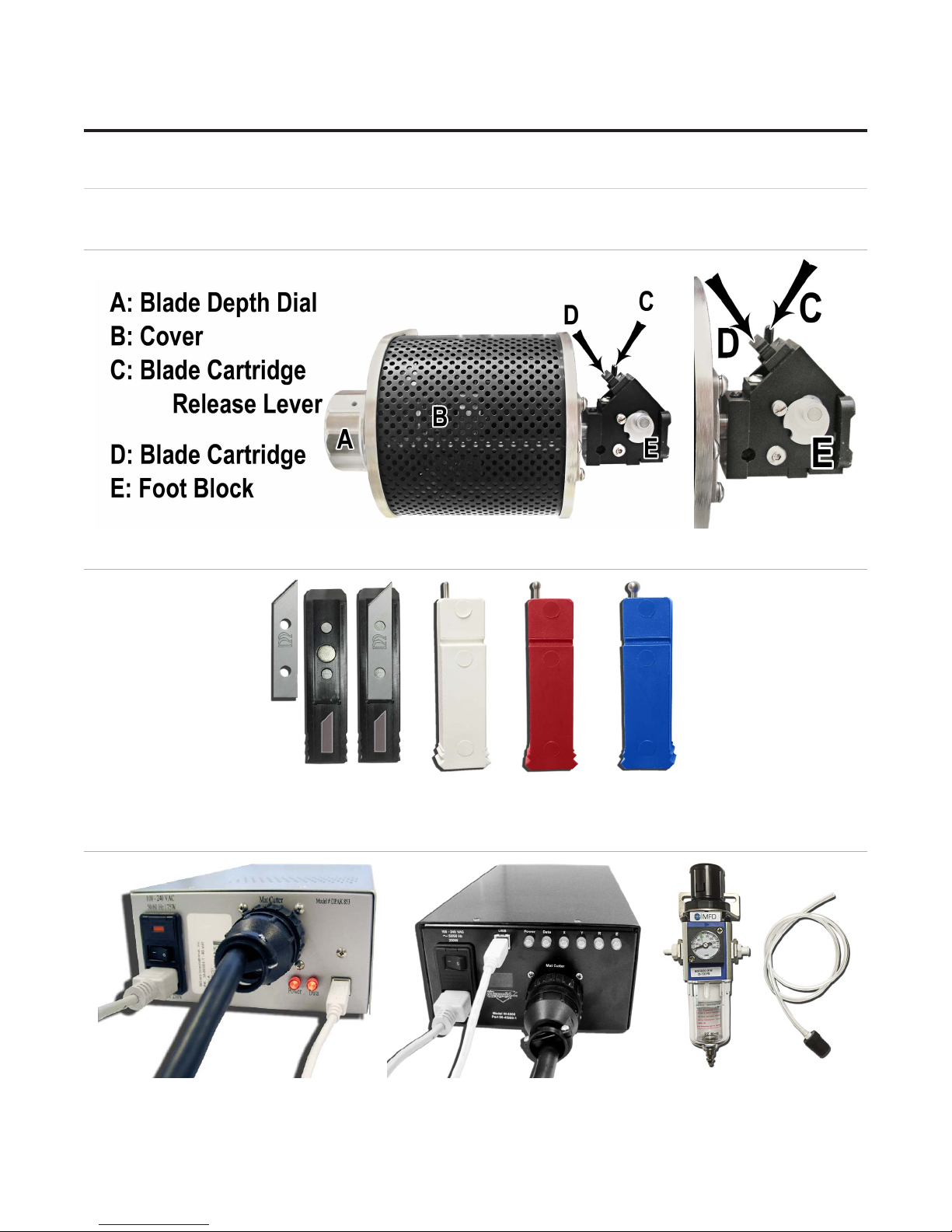
CMC Parts
Head Labeled
Cartridges
45° Deboss Deboss Deboss
Thin Medium Wide
Driver Pack/ECU and Air Regulator
Driver Pack ECU Air Regulator
CMC 8000RC/FrameShop 20-71034-1 GettingStartedManual8000RCFrameShop
http://info.wizardint.com/KB/default.aspx#pageid=getting_started_manual_8000_rc 04/05/19
6
Page 7
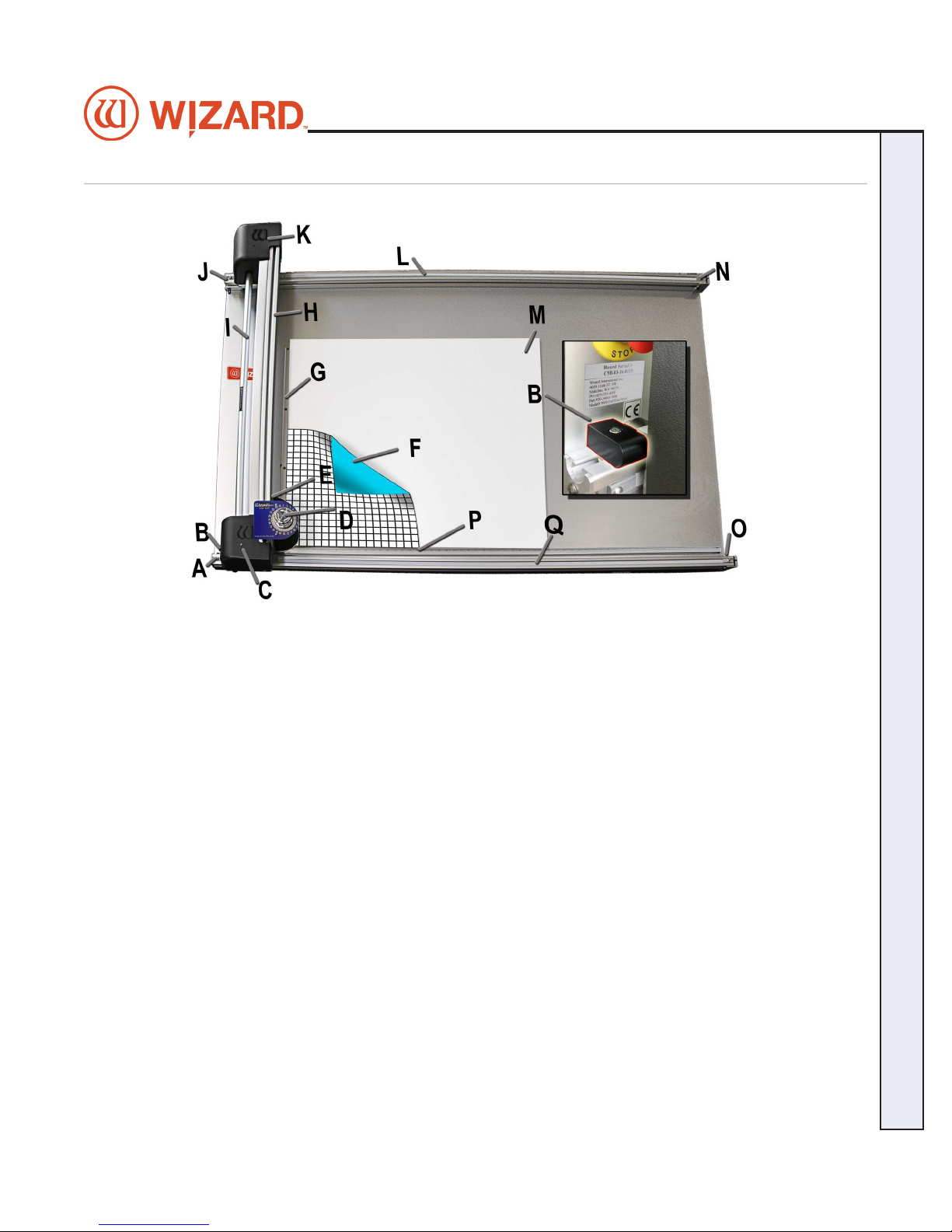
The 8000 CMC Parts Labeled
Wizard CMC Model 8000 RC Hardware and Software Getting Started Manual
A: Belt Anchor
B: Magnetic Stop
C: Bottom cover containing vertical belt tension
adjustment.
D: Head and the blade depth knob
E: Head grabber arm
F: Mat to be cut
G: Vertical clamp
H: Gantry arm
I: Drive shaft
J: Belt anchor
K: Upper cover
L: Upper rail, containing drive belt
M: Backing mat (2 layers)
N: Horizontal tension adjustment (upper rail)
O: Horizontal tension adjustment (lower rail)
P: Horizontal clamp
Q: Lower rail, containing drive belt
CMC 8000RC/Frameshop 20-71034-1 GettingStartedManual8000RCFrameShop
http://info.wizardint.com/KB/default.aspx#pageid=getting_started_manual_8000_rc 04/05/19
7
Page 8
Wizard™ International, Inc., 4600 116th St. SW, Mukilteo, WA 98275 888/855-3335 Fax: 425/551-4350 wizardcutters.com
Setting up the CMC
Congratulations on acquiring the Wizard™ computerized mat cutter (CMC). The following instructions will
walk you through unpacking and setting up the CMC.
Begin by clearing an area for the CMC. Refer to the Stand Instructions for the minimum amount of space
needed.
Setting up the Stand or Wall Mount
CAUTION: The stand MUST be assembled before unpacking
*
the CMC so it can be immediately installed in the operating
position.*
Assembling the Stand Assembly
Refer to the stand assembly instructions located in the box. If the instructions or any parts are missing, call
Technical Support at (888) 855-3335.
Taking the CMC out of the Box
1. With the help of a second person, place the box carefully on a at surface,
cut the strapping tape and lift the cover of the box away. Take care to save the
packaging.
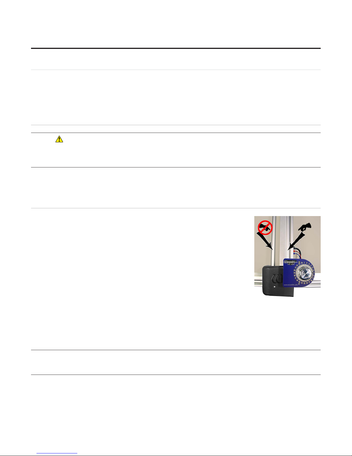
2. The drive shaft is the thin cylindrical bar on the left that runs the length of the
Gantry. The gantry arm is the thick rectangular housing on the right that runs
the length of the gantry. Only use the gantry arm to move the gantry across the
board.
3. Working together, carefully lift the CMC straight up out of the box. Gently set
the CMC upright resting on the foam corners.
4. Position the CMC on the wall mount or stand, making sure that none of the air
lines are crimped, and that the grounding strap on the rear side of the board is not
crimped between the board and stand arm.
5. Remove foam corners and move the boxy out of the way.
6. Follow the instructions that came with the stand to secure the CMC into place and attach the grounding
strap.
7. Place the foam corners back into the box. Save packaging, foam corners and shipping blocks (removal
instructions below) for future use. See Contract Section 1 “Shipping Charges.”
NEVER SKIP AHEAD ON ANY STEP! Never pull/push on the Drive
Shaft to move the Gantry. Use the Gantry Arm.
CMC 8000RC/FrameShop 20-71034-1 GettingStartedManual8000RCFrameShop
http://info.wizardint.com/KB/default.aspx#pageid=getting_started_manual_8000_rc 04/05/19
8
Page 9
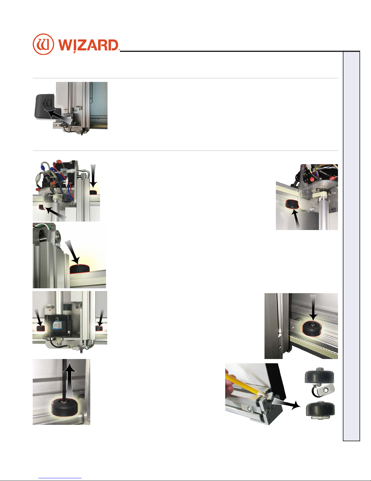
Remove Gantry Cover
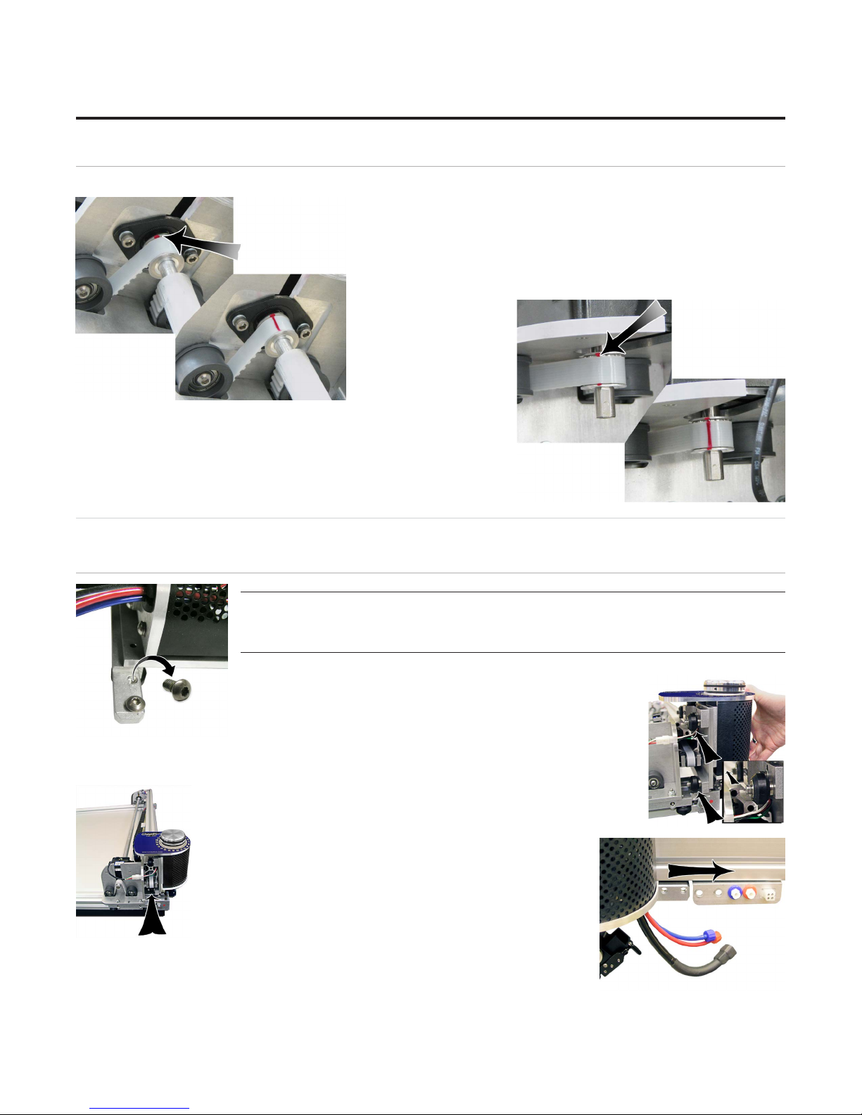
1. Remove the screw holding the bottom gantry cover in place, and set the cover
and screw aside aside.
Removing the Shipping Blocks
1. Locate the four shipping blocks holding the gantry in place.
There are two on the upper gantry. One is to the left of the
gantry on the underside of the top rail,
Wizard CMC Model 8000 RC Hardware and Software Getting Started Manual
and one is to the right of the gantry on the top of the rail.
There are two shipping blocks on the lower gantry on
either side of the gantry on top of the the bottom rail.
2. Remove the shipping blocks by loosening
the 3/16” Allen screw from the T-Nut. Slide
the T-Nuts to the right end of the rail; a pencil
tip helps. Reattach the T-Nuts to the shipping
blocks and place them in the shipping box for
storage.
CMC 8000RC/Frameshop 20-71034-1 GettingStartedManual8000RCFrameShop
http://info.wizardint.com/KB/default.aspx#pageid=getting_started_manual_8000_rc 04/05/19
9
Page 10
Wizard™ International, Inc., 4600 116th St. SW, Mukilteo, WA 98275 888/855-3335 Fax: 425/551-4350 wizardcutters.com
Check Squareness
Check the Drive Belt Lines
1. Move the gantry all the way to the left. Move the gantry slowly
toward the right until a red mark is visible on the drive belt of the
upper gantry. Conrm that the red mark lines up with the red mark
on the drive pulley.
Without moving the gantry, look at the lower drive belt of the
gantry and make sure the red mark lines up on the lower drive
belt and the drive pulley. If they do not, call the Help Desk.
Head Installation
Install the Head onto the Gantry
Do not pick up the Head using the Blade Depth
Knob.
1. Remove the two 5/32" screws from the head and set aside.
2. Move the gantry to the right edge of the CMC.
3. Point the head so that the foot block faces toward the CMC and the wheels are
close to the bottom of the gantry.
4. Line up the wheels on the head to the center channels of
the Gantry arm. Ease the Head onto the gantry arm and ease
the head onto the gantry.
5. Roll the head up on the gantry until it lines up to the head grabber arm
(attached to the right side of the gantry).
CMC 8000RC/FrameShop 20-71034-1 GettingStartedManual8000RCFrameShop
http://info.wizardint.com/KB/default.aspx#pageid=getting_started_manual_8000_rc 04/05/19
10
Page 11
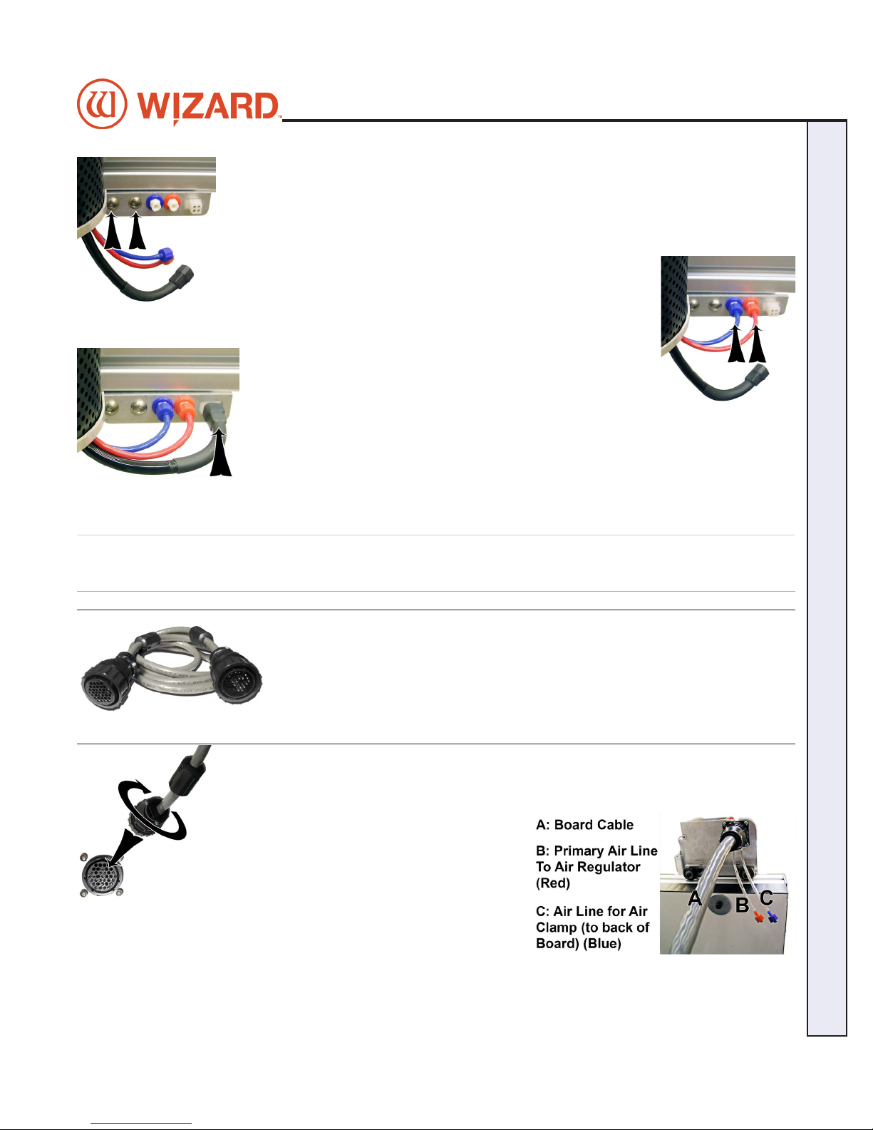
6. Holding the head in position so that the head lines up neatly to the head grabber arm,
replace the two 5/32” screws, making sure they go into the head grabber arm and into the
head and tighten rmly.
7. Connect the air to the head by twisting the two air ttings together, matching colors.
8. Connect the head power plug (square connection) to the
head grabber arm.
Hooking up the Gantry and Air Lines
Wizard CMC Model 8000 RC Hardware and Software Getting Started Manual
Connecting the Board Cable
*Carefully align the pins of the board cable
before applying pressure to plug it in. The
connector is keyed to avoid incorrect pin
alignment. Forcing the connector will result in
damage.*
1. The board cable connects the gantry on the CMC to the Driver Pack/ECU. Connect the
male end of the board cable to the back of the ECU by aligning the pins and turning the
locking ring until it seats itself and locks into place.
2. Connect the female end of the board cable
to the back of the gantry in the same manner.
3. Move the gantry to the far right of the CMC
and back to make sure the board cable does
not get caught on anything. If the board cable
is obstructed, this will aect your cuts.
CMC 8000RC/Frameshop 20-71034-1 GettingStartedManual8000RCFrameShop
http://info.wizardint.com/KB/default.aspx#pageid=getting_started_manual_8000_rc 04/05/19
11
Page 12
Wizard™ International, Inc., 4600 116th St. SW, Mukilteo, WA 98275 888/855-3335 Fax: 425/551-4350 wizardcutters.com
Attaching Air Lines and Air Regulator
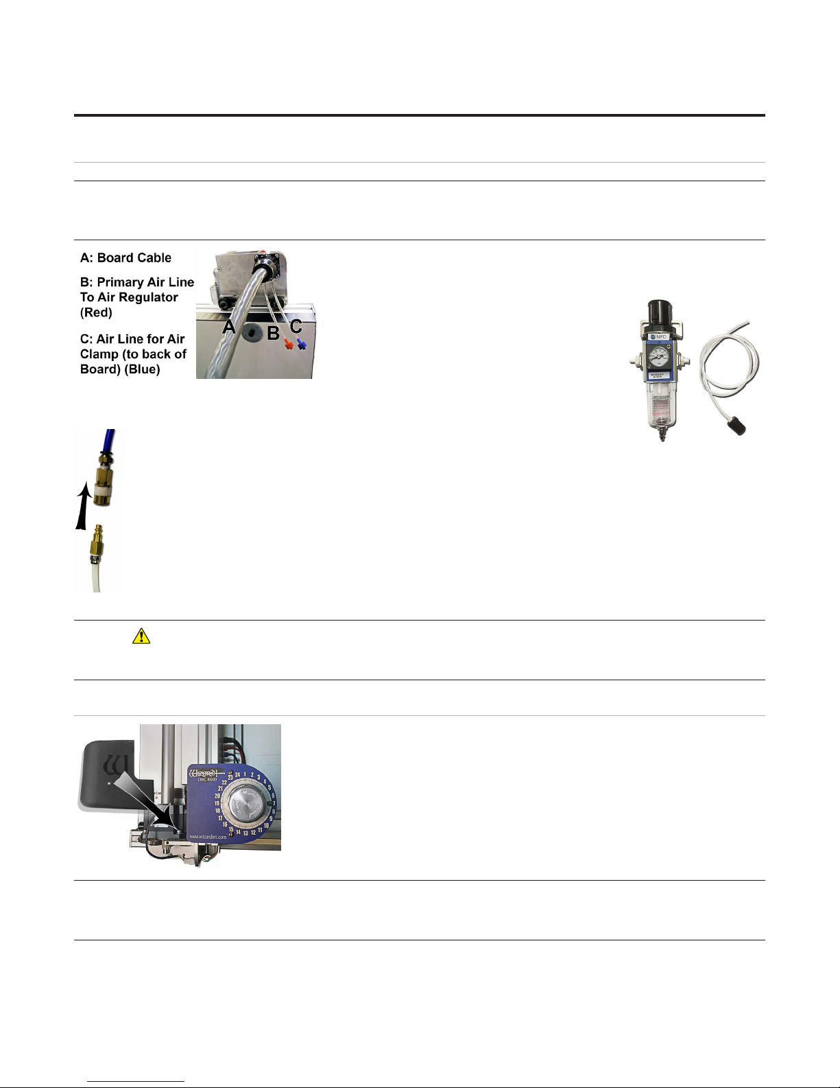
Air Lines are color coordinated. Color refers to connector, not
the color of the tubing.
1. Follow the air line with the blue connector from the top of the gantry.
Make sure that it is connected to the back of the board, and that none
of the air lines are crimped.
2. Follow the air line with the red connector
from the top of the gantry. Connect it to the
right side of the air regulator by inserting the
red connector on the end and twisting it into
place.
3. If it’s not already connected, insert the air regulator line (short air line with reducer)
onto the left connector of the air regulator.
4. Plug the reducer located on the short air line from the left side of the air
regulator into the main air supply via 1/4” NPT female connector or quick
disconnect, whichever type was purchased (shown is the 1/4” NPT female adapter). Teon tape can be
used on the thread to reduce possible air leakage.
5. The air compressor should supply at least 100psi.
6. Strap the air regulator with the glass bowl down to the left large wall bracket or side of stand, making
sure not to crimp any air lines. The hardware to connect the air regulator to the stand is included in the
stand hardware kit.
7. Turn on the air.
* CAUTION: The air regulator is factory-set. Do not make
adjustments to it.*
Install Gantry Cover
1. Replace the gantry cover and attach using the screw that was removed
earlier.
WARNING: To avoid damage to the CMC, do not operate the
CMC without the Hoods in place.
CMC 8000RC/FrameShop 20-71034-1 GettingStartedManual8000RCFrameShop
http://info.wizardint.com/KB/default.aspx#pageid=getting_started_manual_8000_rc 04/05/19
12
Page 13
Hook up Computer
Hook up Computer Peripherals
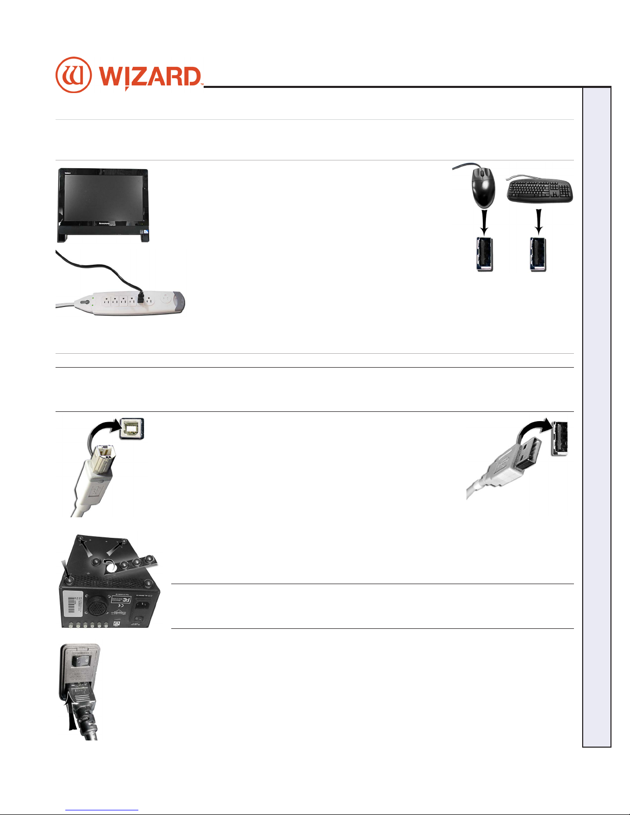
1. Place the computer on the computer stand.
2. Hook up the keyboard and mouse by plugging their USB
cables into the computer. Some of the USB connections are
in the back, and some are available along the side.
3. Plug in the computer power cord into the matching
port on the computer, then plug the power cord from the computer into a surge
protector.
NOTE: You may have to adjust your monitor settings for optimum display.
Connect the Driver Pack/ECU
WARNING: HIGH VOLTAGE! No user serviceable parts inside
the Driver Pack.
Wizard CMC Model 8000 RC Hardware and Software Getting Started Manual
1. Connect USB cable to back of the driver pack/ECU.
2. Plug the other end of the USB cable into the USB port on the
computer. If your system came with a USB hub, plug it in between
the driver pack/ECU and the computer.
3. Attach the rubber feet to the bottom of the driver pack/ECU in
each corner*. The words on the back of the ECU face upright, and will help determine
which side is the bottom. Depending upon your CMC conguration, place the ECU on
the shelf of the stand or if provided, within the mounting brackets provided on the back
of the CMC.
*NOTE: This is VERY important for ventilation of the
electronic components.
4. Plug the power cord into the back of the driver pack/ECU.
CMC 8000RC/Frameshop 20-71034-1 GettingStartedManual8000RCFrameShop
http://info.wizardint.com/KB/default.aspx#pageid=getting_started_manual_8000_rc 04/05/19
13
Page 14

Wizard™ International, Inc., 4600 116th St. SW, Mukilteo, WA 98275 888/855-3335 Fax: 425/551-4350 wizardcutters.com
5. Connect the other end of the ECU power supply plug to the top port behind the
emergency stop on the back of the board. Make sure the plug is rmly inserted to
ensure the grounding wire makes contact.
6. Connect the power cord for the emergency stop into the bottom port on the back of
the board.
7. Connect the other end of the emergency stop power cord into a surge protector.
The other end should be plugged into a surge protector.
8. The board Cable was plugged into the back of the driver pack when we hooked up
the gantry. See "Connecting the Board Cable" on page 11 for more information.
Turn the System On
Power up the Driver Pack/ECU
Press the | on the rocker switch on the back of the driver pack/ECU to turn on the ECU.
*The ECU must be on for the CMC to cut. Press | on the
rocker switch to turn it on.*
Boot the Computer
Turn on the computer. Allow a minute or so for it to power up.
Double-click on the FrameShop icon to start the software.
Design the First Mat
Edit New Mat
1. Click Design on the main screen to create a new design.
CMC 8000RC/FrameShop 20-71034-1 GettingStartedManual8000RCFrameShop
http://info.wizardint.com/KB/default.aspx#pageid=getting_started_manual_8000_rc 04/05/19
14
Page 15
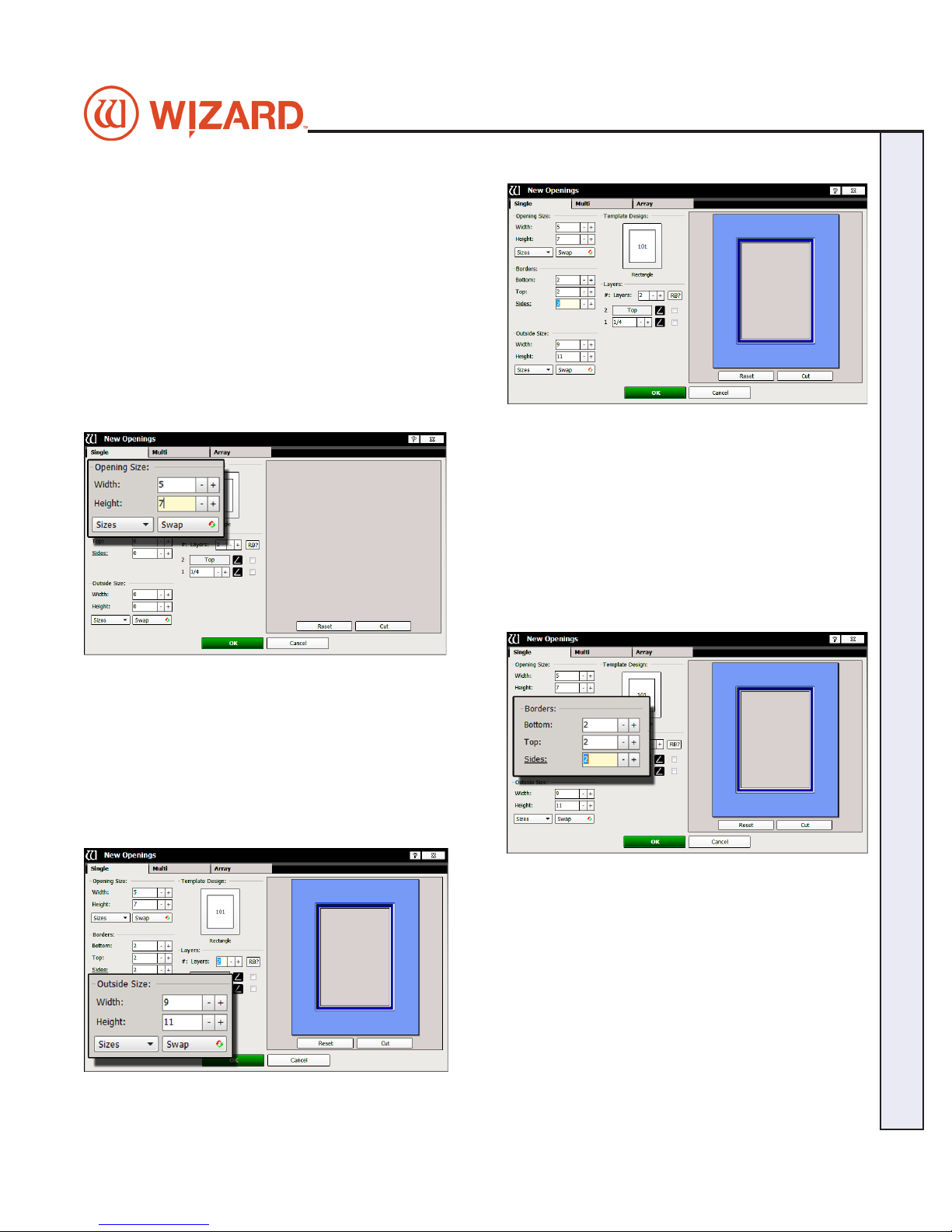
2. Stay on the Single tab. There are three tabs to select
from: Single, Multi, and Array.
Opening Size
3. Enter 5x7 (approx. 13x18 cm) for width and height of the
opening.
NOTE: The Outside size eld will display on the top if Edit
Opening Size First is unchecked in the Admin > Defaults.
Optionally, enter the outside dimensions rst.
Wizard CMC Model 8000 RC Hardware and Software Getting Started Manual
Borders
4. Enter 2 (approx. 5 cm) for the bottom, top and side mat
border widths.
Outside Size
5. Make sure outside size is 9x11 (approx. 23x28 cm).
Don’t Click OK yet.
If opening size and borders are entered rst, the program
automatically calculates the outside size when tabbing out
of the borders eld.
CMC 8000RC/Frameshop 20-71034-1 GettingStartedManual8000RCFrameShop
http://info.wizardint.com/KB/default.aspx#pageid=getting_started_manual_8000_rc 04/05/19
15
Page 16
Wizard™ International, Inc., 4600 116th St. SW, Mukilteo, WA 98275 888/855-3335 Fax: 425/551-4350 wizardcutters.com
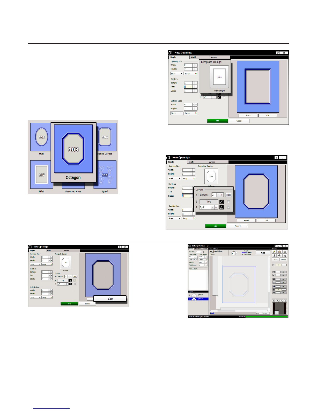
Select Template
6. Click on the template thumbnail under template
design.
7. Template library opens.
Note: There are several pages of templates. Click
on one of the numbered tabs to see a new page.
8. Click on new template thumbnail to select it.
9. The new template is displayed.
Layers
10. Select the number of layers desired for this
project. Leave it at the default of 2 layers.
Go to Cut Preview to Cut the First Mat
1. Click Cut on
the New Openings
Screen to take
design to the Cut
Preview.
CMC 8000RC/FrameShop 20-71034-1 GettingStartedManual8000RCFrameShop
http://info.wizardint.com/KB/default.aspx#pageid=getting_started_manual_8000_rc 04/05/19
16
Page 17
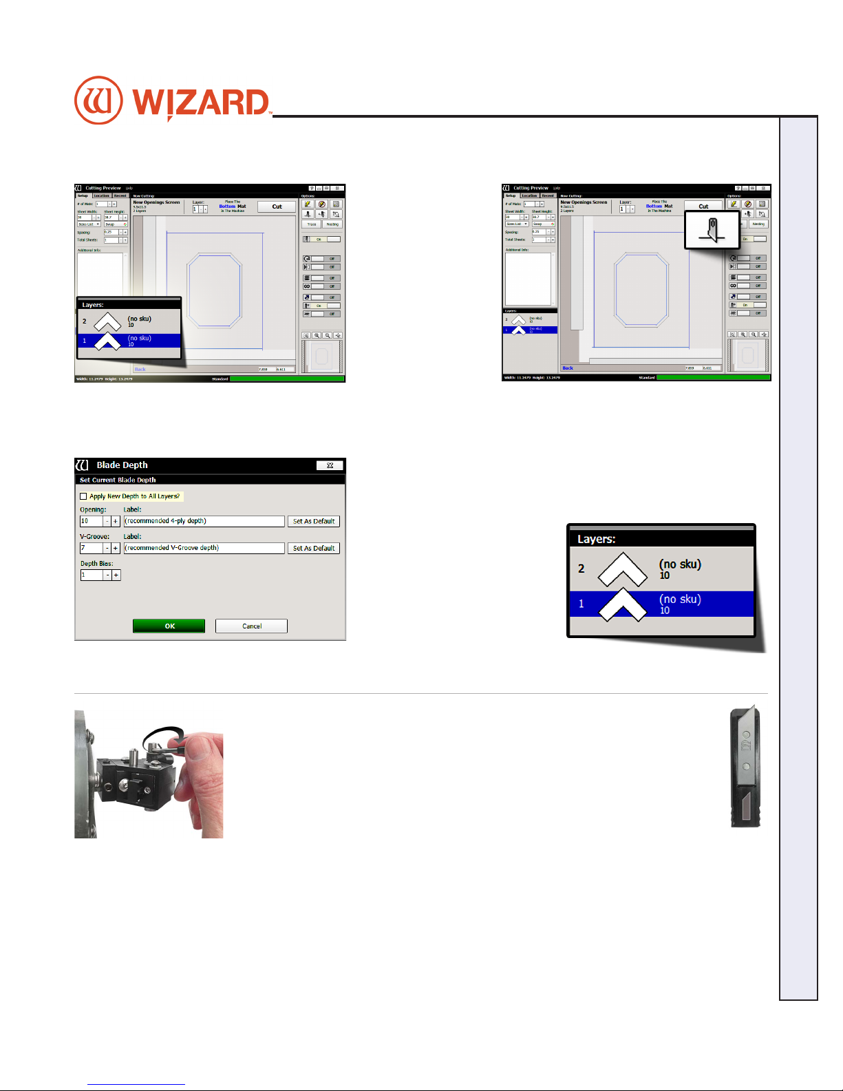
Blade Depth Settings
default blade depth setting.
Wizard CMC Model 8000 RC Hardware and Software Getting Started Manual
1. Select the desired
layer on the Cut
Preview Screen.
2. Click on the Blade
Depth button.
3. On the blade depth screen, select the new blade depth number
under opening if desired.
For this rst mat, leave it at the default setting of 10.
4. Click OK.
5. If we had changed the blade
depth, the new blade depth
number would listed next to the
current layer.
NOTE: Returning to editor then
back to Cut Preview reloads the
Install a Blade
1. Push blade cartridge release down to eject the blade cartridge.
2. The blade cartridge displays a diagram of the blade orientation (shown in
contrast). Place new blade into cartridge with the longest straight side to the
right and the bevel face down, lining up the holes of the blade over the pins in
the cartridge. The blade should t snugly into the recess space provided for it.
3. Turn cartridge over and reinsert into the head with the blade facing the CMC
board and the notch on the back of the cartridge facing the head, until it clicks
into place.
If the blade cartridge does not slide into place, remove it and retry. DO NOT FORCE IN THE BLADE
CARTRIDGE.
CMC 8000RC/Frameshop 20-71034-1 GettingStartedManual8000RCFrameShop
http://info.wizardint.com/KB/default.aspx#pageid=getting_started_manual_8000_rc 04/05/19
17
Page 18
Wizard™ International, Inc., 4600 116th St. SW, Mukilteo, WA 98275 888/855-3335 Fax: 425/551-4350 wizardcutters.com
NOTE: If the blade cartridge is accidently inserted
backward, DO NOT pull upward on the blade cartridge
release as this could result in damage to the footblock
assembly. If you are not able to remove the blade cartridge,
call Help Desk at 888/855-3335.
WARNING: Do not run the CMC without the blade
cartridge in place or damage to the blade cartridge release
lever could occur.
Put Matboard onto CMC
*Make sure there are two layers of disposable
slipsheets of adequate size underneath the mat
to be cut.*
1. The cut preview displays whether the current layer is to be cut from the front
or from the back of the matboard. This determines how to place the matboard
into the CMC.
2. When cutting from the back, place the matboard face down onto the CMC
(facing away from the operator). Make sure the matboard nestles tightly under
the horizontal and vertical clamp of the CMC.
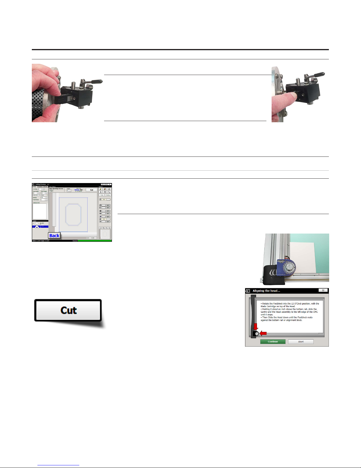
Click Cut
1. Click Cut to cut the mat.
2. If the motors are disengaged, the software
will prompt to Align the Head. When the motors
are disengaged, the gantry can be moved easily
back and forth and the head moves easily
up and down on the gantry. See "Align the Head" on page 19 for
instructions on how to Align the Head.
3. If the head is aligned but a dierent cartridge or blade depth is needed, user will be prompted to change
the blade cartridge and/or the blade depth. See "Insert Blade Cartridge and Adjust Blade Depth" on page
20 for more information.
CMC 8000RC/FrameShop 20-71034-1 GettingStartedManual8000RCFrameShop
http://info.wizardint.com/KB/default.aspx#pageid=getting_started_manual_8000_rc 04/05/19
18
Page 19
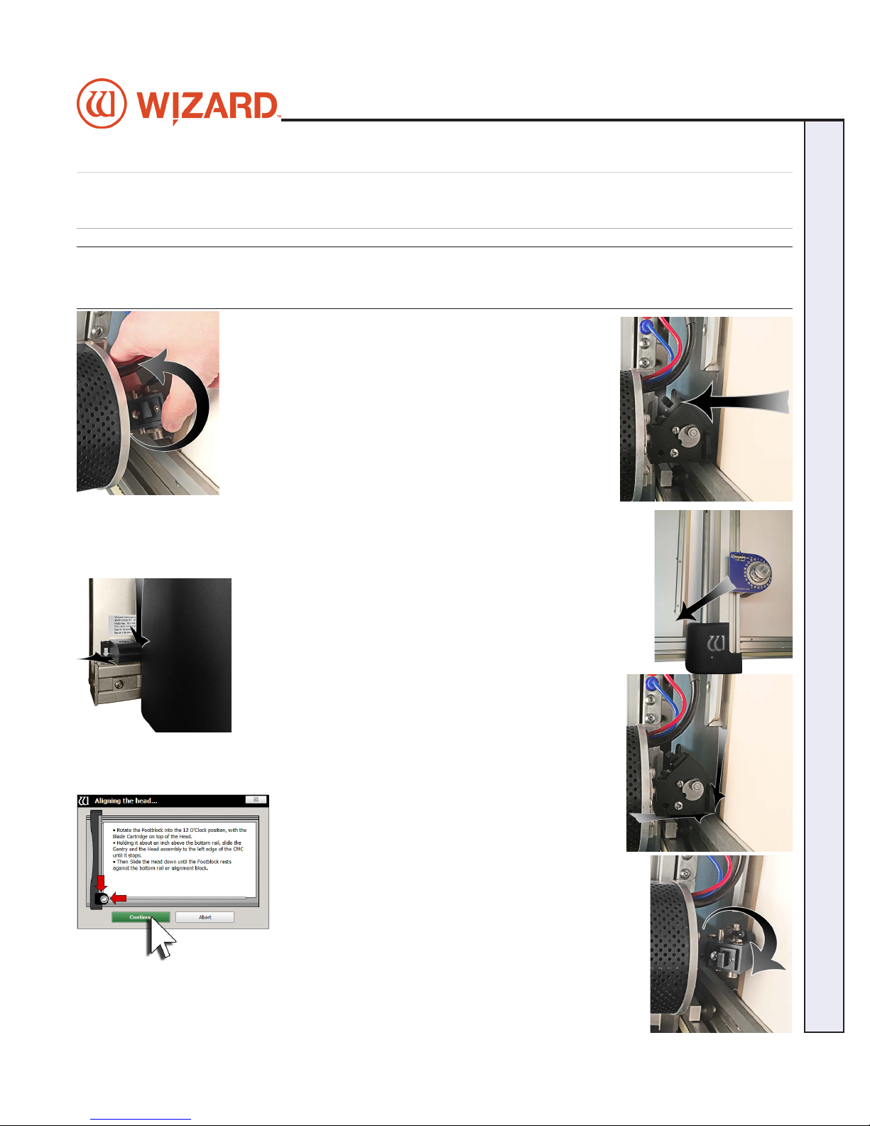
Align the Head When Motors are Disengaged
Align the Head
Never pull/push on the Drive Shaft to move the Gantry. Use the
Gantry Arm.
1. Rotate the foot block into the 12 O’Clock position, with
the blade cartridge on top of the head.
2. Holding it about an inch above the bottom rail, slide the gantry and the head
assembly to the left edge of the CMC until it stops.
Wizard CMC Model 8000 RC Hardware and Software Getting Started Manual
3. It will stop against the Magnetic Stop.
4. Then slide the head down until the foot block rests against the rail.
5. Click on the Align the Head screen.
6. Head will align to the home position.
CMC 8000RC/Frameshop 20-71034-1 GettingStartedManual8000RCFrameShop
http://info.wizardint.com/KB/default.aspx#pageid=getting_started_manual_8000_rc 04/05/19
19
Page 20
Wizard™ International, Inc., 4600 116th St. SW, Mukilteo, WA 98275 888/855-3335 Fax: 425/551-4350 wizardcutters.com
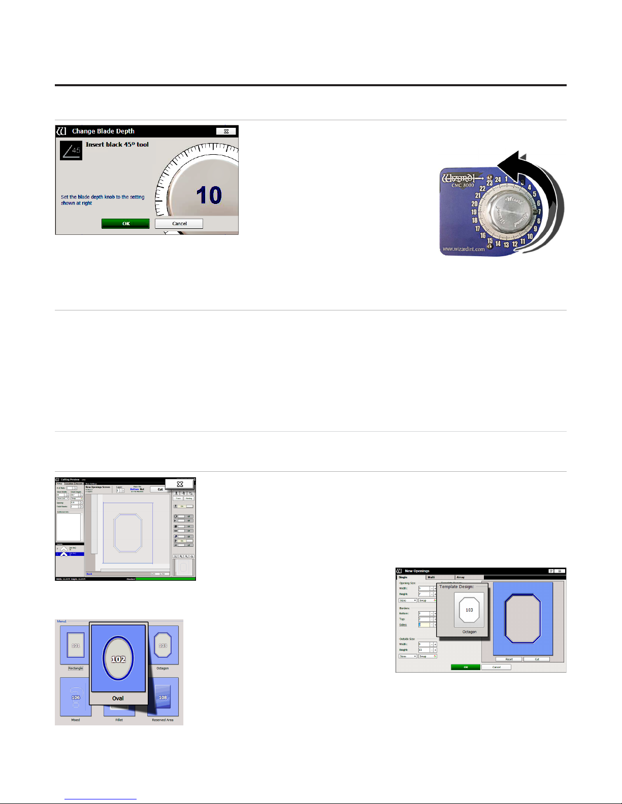
Insert Blade Cartridge and Adjust Blade Depth
If the current layer uses a dierent blade cartridge or is a dierent
thickness than the last layer cut, the
user is prompted to change the blade
cartridge and/or the blade depth.
If the current layer uses the same
blade cartridge and the same thickness
as the last layer cut, the CMC will
begin to cut without further prompt.
The 45° blade cartridge and blade
have already been inserted, so change the blade depth by turning the blade
depth dial to the requested depth and click OK on the prompt.
2. The CMC will begin to cut.
After the CMC Has Cut the Mat
1. After the cut has nished, the head will return to the home position, and the foot block will rotate to the
aligned position for access to the blade cartridge. Unless the screen prompts to align the head, do NOT turn
the foot block.
2. Remove the matboard from the CMC. The rst mat has been cut.
If The Cut Doesn't Look Right
See "Troubleshooting" on page 22.
Design a Dierent Mat
Select a Different Template
1. Click the “X” on the Cut Preview screen to close this screen and return to the
New Openings Screen.
The current design can be easily altered for the next project by changing the
size and other parameters.
This next project is an oval instead of an octagon.
2. Click on the template thumbnail under template design.
3. Template Library opens.
4. Click on new template thumbnail to
select it.
CMC 8000RC/FrameShop 20-71034-1 GettingStartedManual8000RCFrameShop
http://info.wizardint.com/KB/default.aspx#pageid=getting_started_manual_8000_rc 04/05/19
20
Page 21
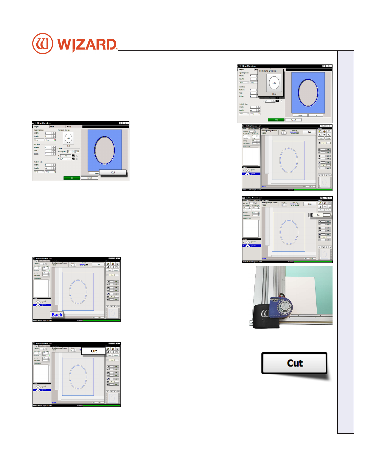
5. The new template is displayed.
Go to Cut Preview
6. Click Cut to go to the Cut Preview
screen.
Outside Cut
7. You can toggle the Outside Cut on or o by clicking the Cut Outside
toggle.
Wizard CMC Model 8000 RC Hardware and Software Getting Started Manual
Put Matboard on the CMC
Click Cut
8. Make sure there are two layers
of disposable backing matboard of
adequate size underneath the matboard to
be cut.
9. This design is cut from the back. Place
the matboard face down onto the CMC
(facing away from the operator). Make
sure the matboard nestles tightly under the
horizontal clamp and vertical clamp of the
CMC.
10. Click Cut to cut the mat.
11. Because the motors are still engaged, the
CMC will automatically begin to cut.
12. After it has nished cutting, remove the
matboard from the CMC. The second mat has
been cut.
13. Click the “X” button to return to the New Openings screen or Click the “X”
button three times to return to the Main Screen.
CMC 8000RC/Frameshop 20-71034-1 GettingStartedManual8000RCFrameShop
http://info.wizardint.com/KB/default.aspx#pageid=getting_started_manual_8000_rc 04/05/19
21
Page 22
Wizard™ International, Inc., 4600 116th St. SW, Mukilteo, WA 98275 888/855-3335 Fax: 425/551-4350 wizardcutters.com
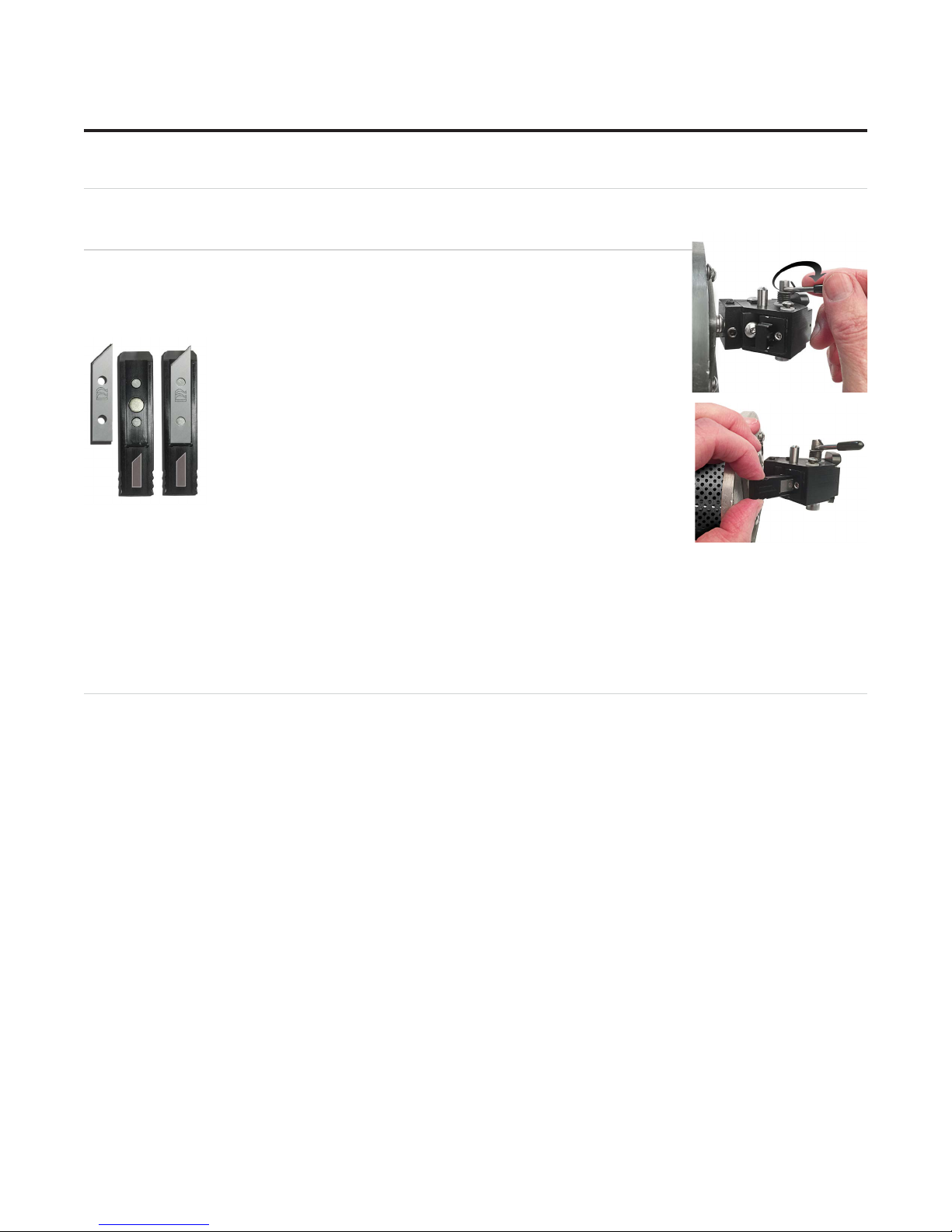
Changing the Blade
Using the 45° Cartridge
Changing the Blade
1. Push the blade cartridge release down to eject the blade cartridge.
2. Remove the blade from blade cartridge.
3. The blade cartridge displays a diagram of the blade orientation
(shown in contrast). Place new blade into cartridge with the
longest straight side to the right and the bevel face down lining up
the holes of the blade over the pins in the cartridge. The blade
should t snugly into the recess space provided for it.
4. Turn the cartridge over and reinsert into the head with the blade
facing the CMC board and the notch on the back of the cartridge
facing the head, until it clicks into place.
If the Blade Cartridge does not slide into place, remove it and retry. DO NOT
FORCE IN THE BLADE CARTRIDGE.
NOTE: If the Blade Cartridge is accidently inserted backward, DO NOT pull upward on the Blade Cartridge
Release as this could result in damage to the Footblock assembly. If you are not able to remove the Blade
Cartridge, call Help Desk at 888/855-3335.
Troubleshooting
Cuts Look Wavy
Check for squareness. See "Check Squareness" on page 10.
Make sure the board cable is unobstructed. See "Connecting the Board Cable" on page 11.
Check the head wheels. See Head Wheel Adjustment at http://info.wizardint.com/KB.
Check the blade depth - See "Insert Blade Cartridge and Adjust Blade Depth" on page 20 and Blade
Depth Adjustment on the Knowledge Base at http://info.wizardint.com/KB.
Blade Keeps Breaking
Check how the blade is installed. See "Install a Blade" on page 17.
Check to make sure the head is properly aligned. See "Align the Head" on page 19.
Check the Blade Depth. See "Blade Depth Setting" on page 17 and Measuring Blade Depth on the
Knowledge Base at http://info.wizardint.com/KB.
CMC 8000RC/FrameShop 20-71034-1 GettingStartedManual8000RCFrameShop
http://info.wizardint.com/KB/default.aspx#pageid=getting_started_manual_8000_rc 04/05/19
22
Page 23

Frequently Asked Questions
Q: When I click cut, it makes a lot of noise and breaks the blade even though I’ve followed the troubleshooting
suggestions. What do I do?
If the motors have been idle (i.e., you can move the head because there is no power to the motors), or if a
cut has been aborted, the head will have to be aligned before cutting. Otherwise, the head is rotated into
the incorrect position and will break the blade. See "Align the Head" on page 19 in this document for
more information.
Q: I click cut and the matboard moves around and does not cut correctly. How do I x this?
Make sure that the air compressor is turned on, and that the air lines are not pinched. The CMC requires
air pressure to engage the clamps and cutting head.
Q: My opening is cut in the wrong place, what should I check?
Make sure you are placing the matboard correctly into the CMC. See "Go to Cut Preview to Cut the
First Mat" on page 16 in this document for further instructions. If the CMC is not cutting the outside
of the mat, re-measure the mat again and make sure that it was trimmed down to the correct size. If the
CMC is cutting the outside of the mat, see the Congurations section on the Knowledge Base at http://
info.wizardint.com/KB to determine if the opening adjustment needs to be adjusted.
Q: What process does the computer use to download corners?
Click check for corners on the license screen. FrameShop will use the internet connection to download
corners. If not connected to the internet, FrameShop can connect to Wizard via a modem.
Q: My FrameShop keeps opening in demo mode and will not cut. What should I check?
Make sure that the ECU is properly hooked up, plugged in and turned on. See "Connect the Driver
Pack/ECU" on page 13 in this document for more information.
Q: How do I order Blades?
You can access our Web Store at www.wizardcutters.com/store or by calling order processing at
888/855-3335.
Q: Do I need to save the packaging the CMC came in?
YES – for warranty purposes, if you ever need to return a part, these boxes will be needed. Rental
customers are required to keep all packaging to return the machine at the end of the rental period.
Q: Why is air leaking from the air regulator when I turn on the air compressor? Is this an issue?
This is normal. One of the purposes of the air regulator is to collect moisture that may be trapped
within the air line. The air regulator is self releasing when the air compressor is turned o. When the
air regulator has built up enough pressure after turning on the air compressor, the air leaking will stop.
If the air compressor is not building enough pressure, the user may install a shut o valve to allow the
compressor to build up enough air pressure.
Q: What process does the computer use to download Corners?
When you Click Check for Corners, FrameShop will check to see if you are connected to the Internet. If
you are connected to the Internet, FrameShop will use that connection to download your corners. If you
are not connected to the Internet, FrameShop will manually dial out to get your corners.
Q: Where can I get more information on specic questions?
Our our Knowledge Base at http://info.wizardint.com/KB has a search feature. See also
"Troubleshooting" on page 22 in this document for more information. You can also call Technical
Support at 888/855-3335 or send an e-mail to [email protected].
Wizard CMC Model 8000 RC Hardware and Software Getting Started Manual
CMC 8000RC/Frameshop 20-71034-1 GettingStartedManual8000RCFrameShop
http://info.wizardint.com/KB/default.aspx#pageid=getting_started_manual_8000_rc 04/05/19
23
Page 24

Wizard™ International, Inc., 4600 116th St. SW, Mukilteo, WA 98275 888/855-3335 Fax: 425/551-4350 wizardcutters.com
Hardware Maintenance
Paper dust is very abrasive. The CMC is a high tech precision piece of equipment that requires periodic
tuning for accurate mat cutting. Damage caused by improper maintenance is not covered by warranty and will
necessitate return of the CMC to the factory for rebuilding/repair.
Maintenance Schedule
Do not spray anything directly on the CMC; spray onto a cloth and then wipe.
Daily:
1. With compressed air or soft brush, clean lower rail, horizontal/vertical clamps and head of any matboard
debris.
2. Check backing mat for excessive wear, and change if necessary.
3. Check blade depth and blade installation.
4. Properly shut down computer and ECU at night.
Weekly:
1. Clean CMC rails with a soft cloth and general purpose cleaner, especially the lower rail where wheels have
the most contact with the machine.
2. Ooad the Air Regulator. See "Ooad Air Regulator" on page 24 for instructions.
Monthly:
1. Clean and drain the air compressor to ensure that the air line is free of moisture and oil. Moisture is very
detrimental to hardware and can cause a variety of problems. Check your air compressor documentation for
instructions.
2. Wipe down foot block on head with a soft cloth and mild cleaner.
3. Remove and clean blade cartridges with adhesive release.
4. Check the blade cartridges for wear and tear. There should not be excessive side-to-side movement of the
blade within the cartridge.
5. Make sure that the CMC is still secure in the brackets/stand to avoid any tip-over hazard.
6. Readjust the head wheels after 250-500 mats. See the Head Wheel Adjustment on the Knowledge Base
at http://info.wizardint.com/KB for instructions.
Offload Air Regulator
One of the purposes of the air regulator is to collect moisture that may be trapped within
the air line. The air regulator is self releasing when the air compressor is turned o.
Check the air regulator at least once a week for any buildup of moisture or oil. If there is
any oil visible in the air regulator, the air compressor needs to be cleaned and drained to
remove the oil in the air line. Refer to the compressor’s documentation for instructions.
The dial on the air regular should read 60psi when the air source is on and at full
pressure. If it does not read 60psi on the gauge, call technical support.
Disclaimers
Caution: The CMC is designed to be used as directed. Any use other than that described within the documentation is
CMC 8000RC/FrameShop 20-71034-1 GettingStartedManual8000RCFrameShop
http://info.wizardint.com/KB/default.aspx#pageid=getting_started_manual_8000_rc 04/05/19
24
Page 25
not supported and potentially harmful to the operator.
Caution: The CMC should not be operated when operator is fatigued, under the inuence of alcohol or narcotics, or
other medication where operating heavy machinery warnings are provided.
Caution: Due to the size and weight of the CMC, two people must perform identied installation operations. Noted
operations performed by a single person may result in injury.
Caution: The CMC contains moving parts that may cause injury if not operated in accordance with the instructions.
Only trained operators should operate machinery. Operators should not touch the CMC while it is cutting a mat.
Warning: Blades used within the CMC are sharp and will cause injury if not disposed of properly. Blades must be
disposed of in an appropriate sharps disposal container.
Warning: Hazardous voltages exist within the ECU. No user serviceable parts are located inside the ECU. Opening of
the ECU is prohibited.
Warning: Do not turn on ECU if board cable is disconnected on either end. Risk of electrical shock is present through
the ECU plug or non-terminated board cable.
© 2003, 2018 by Wizard International, Inc.
Documentation is provided “as is” and all express or implied conditions, representations, and warranties, including any
implied warranty of merchantability, tness for a particular purpose or non-infringement, are disclaimed, except to the
extent that such disclaimers are held to be legally invalid.
Wizard CMC Model 8000 RC Hardware and Software Getting Started Manual
CMC 8000RC/Frameshop 20-71034-1 GettingStartedManual8000RCFrameShop
http://info.wizardint.com/KB/default.aspx#pageid=getting_started_manual_8000_rc 04/05/19
25
Page 26

Wizard™ International, Inc., 4600 116th St. SW, Mukilteo, WA 98275 888/855-3335 Fax: 425/551-4350 wizardcutters.com
No part of this publication may be reproduced or transmitted in any form or for any purpose without the express
permission of Wizard International. The information contained herein may be changed without prior notice.
Adobe, the Adobe logo, Acrobat, PostScript, and Reader are either trademarks or registered trademarks of Adobe
Systems Incorporated in the United States and/or other countries.
Business Objects, Crystal Reports, and other Business Objects products are trademarks or registered trademarks of
Business Objects S.A. in the United States and in other countries.
Canon®, PowerShot™ and Rebel EOS® are trademarks or registered trademark of Canon Inc. in the United States and/
or other countries.
DXF™ is a trademark of Autodesk, Inc., and/or its subsidiaries and/or aliates in the United States and/or other countries.
Microsoft®, Excel®, SQL Server®, Windows®, Windows Vista® and the Windows Vista logo are trademarks or registered
trademarks of Microsoft Corporation in the United States and/or other countries.
Visual CADD is a trademark of Numera Software Corporation.
TrueType is a registered trademark of Apple Computer, Inc.
Wizard™, MatDesigner™, FrameShop™,Virtual Gallery®, SwitchBlade Technology™, the Wizard logo, MatDesigner logo,
FrameShop logo and Integrated Framer logo are trademarks or registered trademarks of Wizard International, Inc. in the
United States and/or other countries.
All other corporate and product names and trademarks mentioned in this manual are the property of their respective
owners.
CMC 8000RC/FrameShop 20-71034-1 GettingStartedManual8000RCFrameShop
http://info.wizardint.com/KB/default.aspx#pageid=getting_started_manual_8000_rc 04/05/19
26
 Loading...