

Wixey WR365 User Manual
TM
ON/ZERO
:
A.
Press once to turn
ON
disp
lay. B.
Press again to set relative angle to 0.0
°.
Wixey
Instructions
Model WR365 Digital Angle Gauge
with Level Patent Pending
Exclusive
flip-up
display
SAFTEY FIRST
• Always turn off the power and unplug power tools before using any gauge.
• Never use power tools without properly installed blade guards. Guards
may not be shown for clarity.
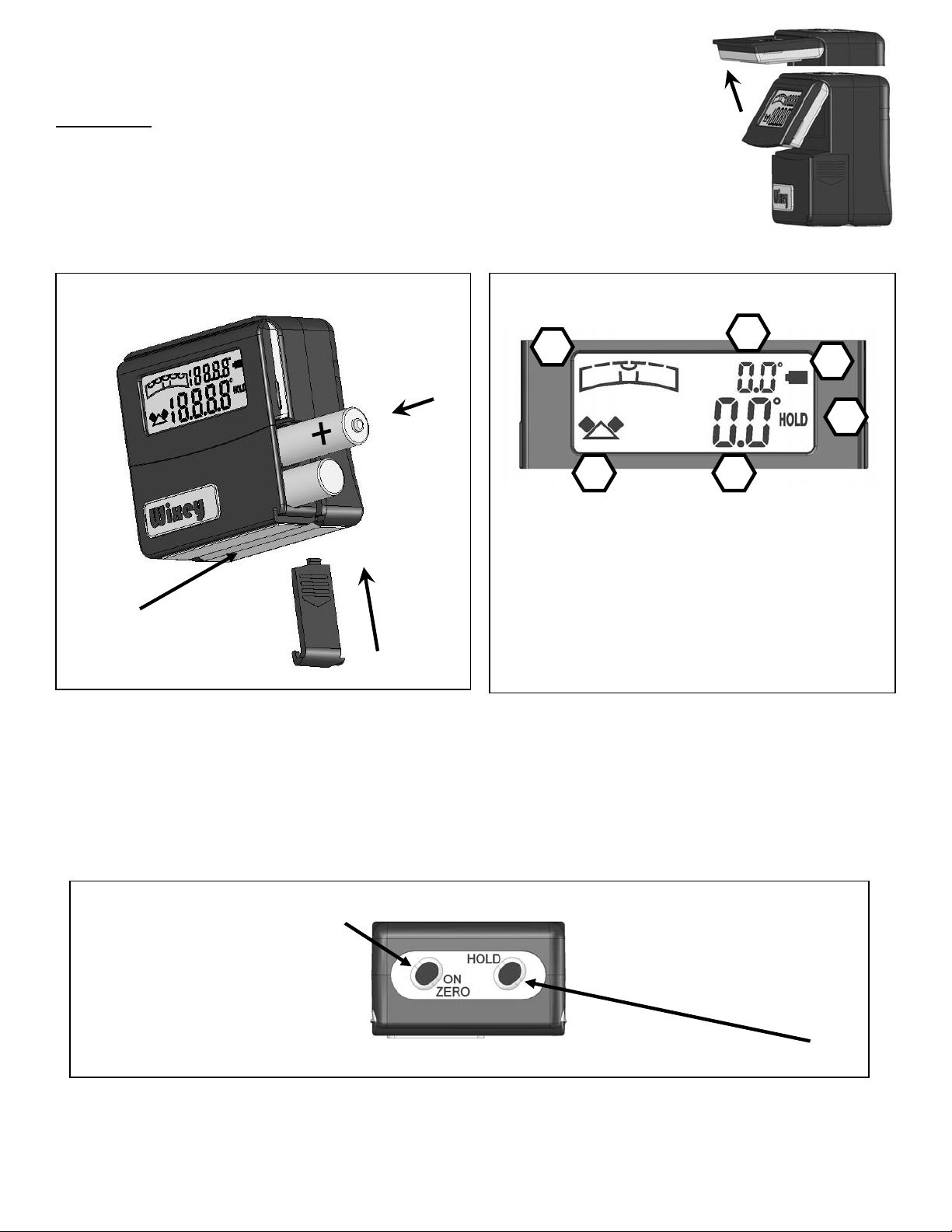
Basic Use
Install two AAA Batteries
FIG 1
READING THE DISPLAY
Note the super strong
magnetic base with “V”
groove for use on pipe
A. Bubble icon permanently set Dead Level
B. Tilt of gauge compared to Dead Level
C. Low battery indicator
D. Indicates the display is in HOLD mode
E. Relative angle reading
F. Indicates direction of tilt from relative 0.0°
*
Dead Level
TM
refers to absolute level with respect to the center of the earth. This
is what is shown with a tradition bubble level when the bubble is in the exact
center of the vial. Our Dead Level
TM
technology consists of a permanently
calibrated level setting which is always being displayed by both the bubble level
icon and the small digital angle reading in the upper right corner of the display.
FIG 2
TM
*
TM
C. Press and hold to turn off.
FIG 3
HOLD Press once to HOLD displayed reading -Press again to return to measuring mode
1
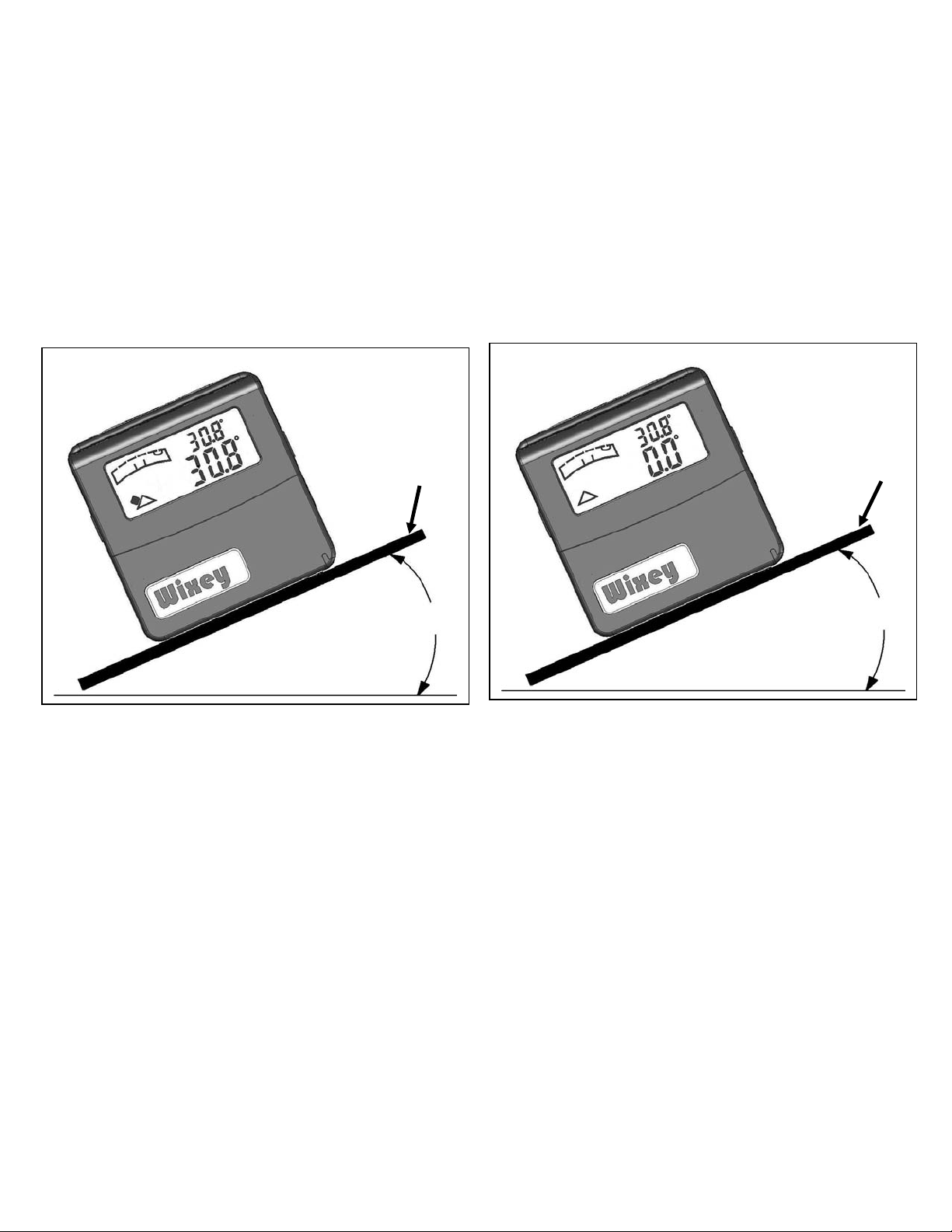
If the relative angle has been set to 0.0 on a level
surface and then placed on a non level reference
surface, both the relative angle measurement and
TM
the Dead Level
display will be the same FIG 4
FIG 4
Reference
surface
30.8°
Level surface
Pressing the ON/ZERO button calibrates the
relative angle to the reference surface and
displays 0.0. The Dead Level
continues to measure the FIG 5
TM
display
Reference
surface
30.8°
Level surface
FIG 5
Proper Measuring
1. Set the gauge flat on a reference surface such as a table saw, miter saw,
or jointer table. On a band saw or drill press the blade or bit will be the
reference surface. Keep the back of the gauge in a plane perpendicular to
the surface being measured. FIG 6
2. Turn on and press the ON/ZERO button to set the gauge to 0.0 degrees
which calibrates the reference surface.
3. Attach to the saw blade or jointer fence using the imbedded magnets. The
back of the gauge must always be kept in the same plane perpendicular to
the reference surface for all measurements. FIG 7
2
 Loading...