


SV7221G2 Series
User Manual
Version 1.1
April
Copyright © 2017 Wiwynn. All rights reserved.

Copyright
Copyright © 2017 by Wiwynn Corporation. All rights reserved. No
part of this publication may be reproduced, transmitted, transcribed,
stored in a retrieval system, or translated into any language or
computer language, in any form or by any means, electronic,
mechanical, magnetic, optical, chemical, manual or otherwise,
without the prior written permission of Wiwynn Corporation.
Disclaimer
The information in this guide is subject to change without notice.
Wiwynn Corporation makes no representations or warranties, either
expressed or implied, with respect to the contents hereof and
specifically disclaims any warranties of merchantability or fitness for
any particular purpose. Any Wiwynn Corporation software
described in this manual is sold or licensed "as is". Should the
programs prove defective following their purchase, the buyer (and
not Wiwynn Corporation, its distributor, or its dealer) assumes the
entire cost of all necessary servicing, repair, and any incidental or
consequential damages resulting from any defect in the software.
2 SV7221G2 Series User Manual

Date
Version
Modifications
2017/01/09
1.0
First release
2017/04/14
1.1
Revised
1. Section 1.1 Specification
2. Section 1.5.4 Mainboard LEDs picture
and table (based on SV7221G2 HW
Spec Rev 0.3.doc).
3. Add Note in Section 4.11 Replacing the
Optional M.2 SSD Card
Revision History
SV7221G2 Series User Manual 3

Information for Your Safety and
Comfort
Safety Instructions
Read these instructions carefully. Keep this document for future reference.
Follow all warnings and instructions marked on the product.
Turn Off the Product before Cleaning
Unplug this product from the wall outlet before cleaning. Do not use liquid
cleaners or aerosol cleaners. Use a damp cloth for cleaning.
Warnings
•
Do not use this product near water.
•
Do not place this product on an unstable cart, stand or table. If the
product falls, it could be seriously damaged.
•
Slots and openings are provided for ventilation to ensure reliable
operation of the product and to protect it from overheating. These
openings must not be blocked or covered. The openings should
never be blocked by placing the product on a bed, sofa, rug or other
similar surface. This product should never be placed near or over a
radiator or heat register, or in a built-in installation unless proper
ventilation is provided.
•
Never push objects of any kind into this product through cabinet slots
as they may touch dangerous voltage points or short-out parts that
could result in a fire or electric shock. Never spill liquid of any kind
onto or into the product.
4 SV7221G2 Series User Manual

•
To avoid damage of internal components and to prevent battery
leakage, do not place the product on a vibrating surface.
•
Never use it under sporting, exercising, or any vibrating environment
which will probably cause unexpected short current or damage rotor
devices, and even exposure risk from lithium battery.
Using Electrical Power
This product should be operated from the type of power indicated on the
marking label. If you are not sure of the type of power available, consult your
dealer or local power company.
Product Servicing
Do not attempt to service this product yourself, as opening or removing
covers may expose you to dangerous voltage points or other risks. Refer all
servicing to qualified service personnel.
When servicing the hot-swappable system fans while power is on, replace
one system fan at a time to avoid system malfunction.
Use both hand to support this product when removing or installing it from the
rack. Do not lift this product using the fan handles.
Remove this product from the rack to cut off the power and refer servicing to
qualified service personnel when:
•
liquid was spilled into the product
•
the product was exposed to rain or water
•
the product has been dropped or the case has been damaged
•
the product exhibits a distinct change in performance, indicating a
SV7221G2 Series User Manual 5

need for service
•
the product does not operate normally after following the operating
instructions
NOTE: Adjust only those controls that are covered by the operating
instructions, since improper adjustment of other controls may
result in damage and will often require extensive work by a
qualified technician to restore the product to normal condition.
6 SV7221G2 Series User Manual

WARNING
Hazardous moving parts. Keep away from
moving fan blades.
CAUTION
Risk of explosion if battery is replaced by an
incorrect type. Dispose of used batteries
according to the instructions.
Disposal Instructions
Do not throw this electronic device into the trash when
discarding. To minimize pollution and ensure utmost
protection of the global environment, please recycle. For
more information on the Waste from Electrical and
Electronics Equipment (WEEE) regulations, please visit the local WEEE
website.
SV7221G2 Series User Manual 7

Contents
Preface ................................ ................................ ....................................... 12
Introduction ...................................................................................... 12
About this Manual ............................................................................ 12
Conventions ..................................................................................... 13
1 System Tour ................................................................................... 14
1.1 System Specification ............................................................ 14
1.1.1 SV7221G2-S Specification ..................................... 14
1.1.2 SV7221G2-V Specification ..................................... 16
1.1.3 SV7221G2-P Specification ..................................... 18
1.2 Front Panel ........................................................................... 20
1.2.1 SV7221G2-S (3.5” HDD) ........................................ 20
1.2.2 SV7221G2-V (Two 2.5” Drives) .............................. 21
1.2.3 SV7221G2-P (Six 2.5” Drives) ................................ 22
1.3 LED Indicators ...................................................................... 23
1.3.1 Front LED Indicators ............................................... 23
1.3.2 LAN Port LED Indicators ......................................... 24
1.4 Node Rear Panel .................................................................. 25
1.5 Mainboard ............................................................................. 26
1.5.1 SV7221G2-V Mainboard Layout ............................. 26
1.5.2 SV7221G2-P/S Mainboard Layout ......................... 28
1.5.3 Mainboard Jumper Settings .................................... 30
1.5.4 Mainboard LEDs ..................................................... 31
1.6 Memory ................................................................................. 33
1.6.1 Memory Placement and Population Rule................ 33
1.6.2 DIMM Configuration ................................................ 35
1.6.3 DIMM Population .................................................... 35
2 Installing the System onto the Rack ............................................ 36
3 Turning System Power On/Off ...................................................... 39
8 SV7221G2 Series User Manual

4 System Upgrades ........................................................................... 40
4.1 Replacing the SV7221G2-S Optional PCIe Card .................. 41
4.1.1 Removing the SV7221G2-S Optional PCIe Card ... 41
4.1.2 Installing the SV7221G2-S Optional PCIe Card ..... 44
4.2 Replacing the SV7221G2-V Optional PCIe Card .................. 47
4.2.1 Removing the SV7221G2-V Optional PCIe Card ... 47
4.2.2 Installing the SV7221G2-V Optional PCIe Card ..... 50
4.3 Replacing the SV7221G2-P Optional PCIe Card .................. 53
4.3.1 Removing the SV7221G2-P Optional PCIe Card ... 53
4.3.2 Installing the SV7221G2-P Optional PCIe Card ..... 55
4.4 Replacing the SV7221G2-S Riser Card ................................ 57
4.4.1 Removing the SV7221G2-S Riser Card ................. 57
4.4.2 Installing the SV7221G2-S Riser Card ................... 59
4.5 Replacing the SV7221G2-V Riser Card ................................ 61
4.5.1 Removing the SV7221G2-V Riser Card ................. 61
4.5.2 Installing the SV7221G2-V Riser Card ................... 62
4.6 Replacing the SV7221G2-P Riser Card ................................ 63
4.6.1 Removing the SV7221G2-P Riser Card ................. 63
4.6.2 Installing the SV7221G2-P Riser Card ................... 64
4.7 Replacing the SV7221G2-S Drive and Drive Module ........... 65
4.7.1 Removing the SV7221G2-S Drive Module ............. 65
4.7.2 Installing the SV7221G2-S Drive Module ............... 68
4.7.3 Removing the SV7221G2-S HDD ........................... 71
4.7.4 Installing the SV7221G2-S HDD ............................. 72
4.8 Replacing the SV7221G2-V Storage Drives and
Drive Module......................................................................... 73
4.8.1 Removing the SV7221G2-V Storage Drive ............. 73
4.8.2 Installing the SV7221G2-V Storage Drive ............... 74
4.8.3 Removing the SV7221G2-V Drive Module ............. 75
4.8.4 Installing the SV7221G2-V Drive Module ............... 77
4.9 Replacing the SV7221G2-P Drives and Drives Module ........ 79
4.9.1 Removing the SV7221G2-P Storage Drive ............. 79
4.9.2 Installing the SV7221G2-P Storage Drive ............... 80
4.9.3 Removing the SV7221G2-P Drive Module ............. 81
4.9.4 Installing the SV7221G2-P Drive Module ............... 84
4.10 Replacing the Mezzanine Card ............................................. 87
4.10.1 Removing the Mezzanine Card .............................. 87
4.10.2 Installing the Mezzanine Card ................................ 88
SV7221G2 Series User Manual 9

4.11 Replacing the Optional M.2 SSD Card ................................. 89
4.11.1 Removing the Optional M.2 SSD Card ................... 89
4.11.2 Installing the Optional M.2 SSD Card ..................... 90
4.12 Replacing the RTC Battery ................................................... 91
4.12.1 Removing the RTC Battery ..................................... 91
4.12.2 Installing the RTC Battery ....................................... 93
4.13 Replacing the System Cover ................................................ 94
4.13.1 Removing the System Cover .................................. 94
4.13.2 Installing the System Cover .................................... 95
4.14 Replacing the System Fan .................................................... 96
4.14.1 Removing the System Fan ..................................... 96
4.14.2 Installing the System Fan ....................................... 97
4.15 Replacing the Memory Modules ........................................... 99
4.15.1 Removing the Memory Module ............................... 99
4.15.2 Installing the Memory Modules ............................. 100
4.16 Replacing the Heat Sink ..................................................... 101
4.16.1 Removing the Heat Sink ....................................... 101
4.16.2 Installing the Heat Sink ......................................... 102
4.17 Replacing the Processor ..................................................... 103
4.17.1 Removing the Processor ...................................... 103
4.17.2 Installing the Processor ........................................ 106
4.18 Bus Bar Connector ............................................................. 109
4.18.1 Disengaging the Bus Bar Connector..................... 109
4.18.2 Installing the Bus Bar Cables ................................ 111
4.19 Replacing the Mainboard .................................................... 113
4.19.1 Removing the Mainboard ...................................... 113
4.19.2 Installing the Mainboard ........................................ 115
4.20 Installing the Optional Debug Card ..................................... 117
5 BIOS Setup ................................................................................... 118
5.1 Entering BIOS Setup .......................................................... 118
5.2 BIOS Hotkeys ..................................................................... 118
5.3 Menu Bar ............................................................................ 119
5.4 Navigation Keys .................................................................. 120
5.5 Main ................................ ................................ .................... 121
10 SV7221G2 Series User Manual

5.6 Advanced ............................................................................ 122
5.7 IntelRCSetup ...................................................................... 123
5.8 Server Mgmt ................................ ................................ ....... 124
5.9 Security ............................................................................... 125
5.10 Boot .................................................................................... 126
5.11 Save & Exit ......................................................................... 127
6 Post Code Table ........................................................................... 128
6.1 SEC Phase ......................................................................... 128
6.2 PEI Phase ........................................................................... 129
6.3 DXE Phase ......................................................................... 132
6.4 BDS Phase ......................................................................... 134
6.5 ACPI/ASL Checkpoints ....................................................... 136
6.6 DIMM Error Code Post ....................................................... 137
6.7 QPI Error Code Post ........................................................... 146
6.8 Whea Error Code Post ........................................................ 148
6.9 Beep Error LED .................................................................. 149
SV7221G2 Series User Manual 11

Preface
With a high-density design of three servers within one 2U space, Wiwynn
SV7221G2 server minimizes infrastructure power and cost by removing
unnecessary components.
Introduction
Wiwynn SV7221G2 server features dual Intel® Xeon® Processor E5-2600 V4
series supporting up to 512GB DDR4 (16 slots) for improved performance
and system operations.
About this Manual
The contents in this manual include:
Chapter 1 – describes the system specification, front and rear components,
mainboard layout and memory population
Chapter 2 – shows how to install the system onto the rack
Chapter 3 – shows how to power on the system
Chapter 4 – shows how to replace or upgrade system components
Chapter 5 – shows a brief introduction of the BIOS
Chapter 6 – lists the POST code table
12 SV7221G2 Series User Manual

WARNING
Indicates the presence of a hazard that may
result in serious personal injury if the
WARNING is ignored.
CAUTION
Indicates the presence of a hazard that may
cause minor personal injury or property
damage if the CAUTION is ignored.
Conventions
SV7221G2 Series User Manual 13

Processor, Memory, and Chipset
Processor
Intel® Xeon
®
Processor E5-2600V4 series
Memory
Up to 512GB; 8GB/16GB/32GB DDR4 up to 2400MT/s;
16 DIMM slots
Chipset
Intel® C610 series
System Bus
Intel Quick Path Interconnect (QPI) links;
6.4 GT/s; 8.0 GT/s; 9.6 GT/s
Processor
Sockets
Two per node (3 server nodes in a 2 OU shelf)
Storage and I/O
RAID Functions
RAID 0/1/10/5 on PCH
Storage
One 3.5” SAS/SATA hard drive bay
One M.2 SSD module slot
Expansion
Slots
One x16 PCIe slot
One x8 PCIe slot
One mezzanine slot:
‧ Single/Dual 10GbE DA/SFP+ ports (option)
‧ Single/Dual 25GbE SFP28 ports (option)
‧ Single/Dual 40GbE QSFP ports (option)
VGA
ASPEED AST2400 iBMC chip
Note: To use the offboard M.2 VGA card as the main
display output, set the Miscellaneous Configuration
in BIOS Setup to Offboard Device. You can only use
the iKVM function on the offboard M.2 VGA card if it
is not the main display output.
1 System Tour
1.1 System Specification
1.1.1 SV7221G2-S Specification
14 SV7221G2 Series User Manual

Remote
Management
IPMI V2.0 compliant; Serial-over-LAN; Remote
Management Controller (option) ; Cluster Manager (option)
Storage and I/O
LAN
One 1GbE LAN port (option)
Power Supply
Externally through centralized 12V DC bus bar
Power Supply, Physical and Packaging Specifications
Power
Consumption
108W (Idle) ~ 313W (Max)
Weight
Per node: 6.9 kg ~ 7.3 kg
Dimensions
89 (H) * 174 (W) * 880 (D) (mm)
Rack Mount
Kits
Optional cubby for three SV7221G2 servers
Operating System
Support list
CentOS 7.1 (64 bits)
SV7221G2 Series User Manual 15

Processor, Memory, and Chipset
Processor
Intel® Xeon
®
Processor E5-2600V4 series
Memory
Up to 512GB; 8GB/16GB/32GB DDR4 up to 2400MT/s;
16 DIMM slots
Chipset
Intel® C610 series
System Bus
Intel Quick Path Interconnect (QPI) links;
6.4 GT/s; 8.0 GT/s; 9.6 GT/s
Processor
Sockets
Two per node (3 server nodes in a 2 OU shelf)
Storage and I/O
RAID Functions
RAID 0/1/10/5 on PCH
Storage
Two 2.5” SAS/SATA/SSD drive bays
One M.2 SSD module slot
Expansion
Slots
Three x8 PCIe slot
One mezzanine slot:
‧ Single/Dual 10GbE DA/SFP+ ports (option)
‧ Single/Dual 25GbE SFP28 ports (option)
‧ Single/Dual 40GbE QSFP ports (option)
VGA
ASPEED AST2400 iBMC chip
Note: To use the offboard M.2 VGA card as the main
display output, set the Miscellaneous Configuration
in BIOS Setup to Offboard Device. You can only use
the iKVM function on the offboard M.2 VGA card if it
is not the main display output.
Remote
Management
IPMI V2.0 compliant; Serial-over-LAN
Remote Management Controller (option) ; Cluster Manager
(option)
LAN
One 1GbE LAN port (option)
1.1.2 SV7221G2-V Specification
16 SV7221G2 Series User Manual

Power Supply, Physical and Packaging Specifications
Power Supply
Externally through centralized 12V DC bus bar
Power
Consumption
120W (Idle) ~ 325W (Max)
Weight
Per node: 8 kg ~ 9.5 kg
Dimensions
89 (H) * 174 (W) * 880 (D) (mm)
Rack Mount
Kits
Optional cubby for three SV7221G2 servers
Operating System
Support list
VMware ESXi 5.5
Windows® Server 2012 R2
CentOS 6.3 (64 bits)
SV7221G2 Series User Manual 17

Processor, Memory, and Chipset
Processor
Intel® Xeon
®
Processor E5-2600V4 series
Memory
Up to 512GB; 8GB/16GB/32GB DDR4 up to 2400MT/s;
16 DIMM slots
Chipset
Intel® C610 series
System Bus
Intel Quick Path Interconnect (QPI) links;
6.4 GT/s; 8.0 GT/s; 9.6 GT/s
Processor
Sockets
Two per node (3 server nodes in a 2 OU shelf)
Storage and I/O
RAID Functions
RAID 0/1/10/5 on PCH
Storage
Six 2.5” SAS/SATA/SSD drive bays
One M.2 SSD module slot
Expansion
Slots
One x16 PCIe slot
One x8 PCIe slot (dedicated for RADI card)
One mezzanine slot:
‧ Single/Dual 10GbE DA/SFP+ ports (option)
‧ Single/Dual 25GbE SFP28 ports (option)
‧ Single/Dual 40GbE QSFP ports (option)
VGA
ASPEED AST2400 iBMC chip
Note: To use the offboard M.2 VGA card as the main
display output, set the Miscellaneous Configuration
in BIOS Setup to Offboard Device. You can only use
the iKVM function on the offboard M.2 VGA card if it
is not the main display output.
Remote
Management
IPMI V2.0 compliant; Serial-over-LAN
Remote Management Controller (option) ; Cluster Manager
(option)
1.1.3 SV7221G2-P Specification
18 SV7221G2 Series User Manual

LAN
One 1GbE LAN port (option)
Power Supply
Externally through centralized 12V DC bus bar
Power Supply, Physical and Packaging Specifications
Power
Consumption
120W (Idle) ~ 325W (Max)
Weight
Per node: 8 kg ~ 9.5 kg
Dimensions
89 (H) * 174 (W) * 880 (D) (mm)
Rack Mount
Kits
Optional cubby for three SV7221G2 servers
Operating System
Support list
VMware ESXi 5.5
Windows® Server 2012 R2
CentOS 6.3 (64 bits)
SV7221G2 Series User Manual 19

Item
Component
Item
Component
1
Riser card
8
HDD LED (green)
2
HDD
9
Beep LED (yellow)
3
PCI-E expansion slots
10
USB port
4
Power button
11
Mezzanine card with LAN ports
5
Debug card connector
12
mSATA module slot
6
Reset button
13
LAN port
7
Power LED (blue)
1.2 Front Panel
1.2.1 SV7221G2-S (3.5” HDD)
The illustration below shows the front panel with one 3.5” hard disk drive.
20 SV7221G2 Series User Manual

Item
Component
Item
Component
1
PCIe expansion slots
7
HDD LED (green)
2
2.5” drive bays
8
Beep LED (yellow)
3
Power button
9
USB port
4
Debug card connector
10
Mezzanine card with LAN ports
5
Reset button
11
2.5” drive status LEDs
6
Power LED (blue)
12
LAN port
1.2.2 SV7221G2-V (Two 2.5” Drives)
The illustration below shows the front panel with two 2.5” drives.
SV7221G2 Series User Manual 21

Item
Component
Item
Component
1
PCIe expansion slots
7
HDD LED (green)
2
2.5” drive bays
8
Beep LED (yellow)
3
Power button
9
USB port
4
Debug card connector
10
Mezzanine card with LAN ports
5
Reset button
11
2.5”drive status LEDs
6
Power LED (blue)
12
LAN port
1.2.3 SV7221G2-P (Six 2.5” Drives)
The illustration below shows the front panel with six 2.5” drives.
22 SV7221G2 Series User Manual

No.
LED
Color
Description
1
Beep
Yellow
This LED lights up for the same duration and
sequence as the PC speaker would normally beep.
2
HDD
Green
Hard drive activity. This LED only lights up when
there is activity on the mainboard hard drive
interfaces.
3
Power
Blue
This power LED only lights up if the mainboard
power is on.
1.3 LED Indicators
The front and LAN LED indicators are the same for all three models.
1.3.1 Front LED Indicators
SV7221G2 Series User Manual 23

LED indicator
LED color
LED state
Status
RJ45 LED (Right)
Green
On
Active connection
Green
Blinking
Transmit/Receive activity
N/A
Off
No connection
RJ45 LED (Left)
Yellow
On
1000 Mbps
Green
On
100 Mbps
N/A
Off
No connection or 10 Mbps
1.3.2 LAN Port LED Indicators
24 SV7221G2 Series User Manual

No.
Component
1
System fan 1
2
Bus bar connector
3
System fan 2
1.4 Node Rear Panel
The illustration below shows the node rear panel (same for all three models).
SV7221G2 Series User Manual 25

No.
Connector
Description
1
RJ1
RJ45 port
2
BMC1
BMC chip
3
MSATA1
M.2 connector
4
PCIE1
Expansion slot (for riser card)
5
MEZCN1
Mezzanine card connector
6
DIMMA4
CPU0 A4 DDR4 memory slot
7
DIMMA5
CPU0 A5 DDR4 memory slot
8
DIMMA6
CPU0 A6 DDR4 memory slot
9
DIMMA7
CPU0 A7 DDR4 memory slot
10
CPU0
CPU socket
11
DIMMB0
CPU1 B0 DDR4 memory slot
12
DIMMB1
CPU1 B1 DDR4 memory slot
13
DIMMB2
CPU1 B2 DDR4 memory slot
1.5 Mainboard
1.5.1 SV7221G2-V Mainboard Layout
26 SV7221G2 Series User Manual

No.
Connector
Description
14
DIMMB3
CPU1 B3 DDR4 memory slot
15
CPU1
CPU socket
16
PWRCN2
Bus bar power connector with press-fit cable
17
FANCN1
System fan 1 connector
18
FANCN2
System fan 0 connector
19
DIMMB4
CPU1 B4 DDR4 memory slot
20
DIMMB5
CPU1 B5 DDR4 memory slot
21
DIMMB6
CPU1 B6 DDR4 memory slot
22
DIMMB7
CPU1 B7 DDR4 memory slot
23
DIMMA0
CPU0 A0 DDR4 memory slot
24
DIMMA1
CPU0 A1 DDR4 memory slot
25
DIMMA2
CPU0 A2 DDR4 memory slot
26
DIMMA3
CPU0 A3 DDR4 memory slot
27
MiniSAS1
Mini-SAS cable connector
28
HDPR1
SATA power cable connector
29
SATA1
SATA cable connector
30
PWRON1
Power button
31
RESET1
Reset button
32
DBG1
Debug card connector
33
USB2
Front USB connector
SV7221G2 Series User Manual 27

No.
Connector
Description
1
RJ1
RJ45 port
2
BMC1
BMC chip
3
MSATA1
M.2 connector
4
PCIE1
Expansion slot (for riser card)
5
MEZCN1
Mezzanine card connector
6
DIMMA4
CPU0 A4 DDR4 memory slot
7
DIMMA5
CPU0 A5 DDR4 memory slot
8
DIMMA6
CPU0 A6 DDR4 memory slot
9
DIMMA7
CPU0 A7 DDR4 memory slot
10
CPU0
CPU socket
11
DIMMB0
CPU1 B0 DDR4 memory slot
12
DIMMB1
CPU1 B1 DDR4 memory slot
13
DIMMB2
CPU1 B2 DDR4 memory slot
14
DIMMB3
CPU1 B3 DDR4 memory slot
1.5.2 SV7221G2-P/S Mainboard Layout
28 SV7221G2 Series User Manual

No.
Connector
Description
15
CPU1
CPU socket
16
PWRCN2
Bus bar power connector with press-fit cable
17
FANCN1
System fan 1 connector
18
FANCN2
System fan 0 connector
19
DIMMB4
CPU1 B4 DDR4 memory slot
20
DIMMB5
CPU1 B5 DDR4 memory slot
21
DIMMB6
CPU1 B6 DDR4 memory slot
22
DIMMB7
CPU1 B7 DDR4 memory slot
23
DIMMA0
CPU0 A0 DDR4 memory slot
24
DIMMA1
CPU0 A1 DDR4 memory slot
25
DIMMA2
CPU0 A2 DDR4 memory slot
26
DIMMA3
CPU0 A3 DDR4 memory slot
27
HDPR1
SATA power cable connector
28
SATA1
SATA cable connector
29
PWRON1
Power button
30
RESET1
Reset button
31
DBG1
Debug card connector
32
USB2
Front USB connector
SV7221G2 Series User Manual 29

Jumper
Setting
Description
JP1
1-2: Disable BMC
Disable AST2400 BMC
2-3: Normal BMC (Default)
JP2
1-2: 517.5W
Choose power limit level
2-3: 610W (Default)
JP3
1-2: Normal (Default)
Clear CMOS
2-3: Clear CMOS
JP4
1-2: Normal (Default)
ME recovery mode
2-3: ME Recovery mode
JP5
1-2: P5V(Default)
UART power select
2-3: P5V_STBY
JP6
1-2: Normal (Default)
BIOS recovery mode
2-3: Recover BIOS
JP7
Insert jumper = Enable Top Swap
Remove jumper = Normal (Default)
Top Swap
JP14
JP15
1-2: Normal (Default)
UART switch
2-3: Force select UART channel
1.5.3 Mainboard Jumper Settings
This section shows the jumper locations and settings (same for all three
models). Note that jumpers not indicated are for test purposes only.
30 SV7221G2 Series User Manual

1.5.4 Mainboard LEDs
This section shows the mainboard LEDs, functions and status (same for all
three models).
SV7221G2 Series User Manual 31

LED
location
LED
function
LED Status
PWLED1
Power LED
LED consistently off =>Power off, Chassis identify off
LED on for 0.1sec, off for 0.9sec, and loop=>Power off,
Chassis identify on
LED consistently on Power on=>Chassis identify off
LED on for 0.9sec, off for 0.1sec, and loop=>Power on,
Chassis identify on
HDLED1
HDD LED
Blinking=>HDD active
BPLED1
Boot up LED
On=>System boot up
LED63
BMC
Hearbeat
LED
Blinking=> BMC active
LED64
CATERR
LED
1. LED always on means IERR happen.
2. LED blink at 1Hz when MCERR happen.
LED46
CPLD
Debug
TBD
LED47
CPLD
Debug
CPLD state machine code
LED50
LED48
LED47
LED49
MSB
LSB
Description is attached.
cpld.png
LED48
CPLD
Debug
LED49
CPLD
Debug
LED50
CPLD
Debug
ULED1
UART ID
(ULED1 off, ULED2 off) : HOST UART, Default
(ULED1 off, ULED2 on) : BMC Debug
(ULED1 on, ULED2 off) : Midplane UART
ULED2
UART ID
32 SV7221G2 Series User Manual

1.6 Memory
1.6.1 Memory Placement and Population Rule
A memory channel can have 1 or 2 DIMMs installed. If only one DIMM is
installed, the lower digital notation DIMM socket should be used first, for
example, install DIMM in DIMM A0, DIMM B0 and so on. Some DIMM
sockets are color-coded for easier loading.
This platform does not support mixing of DIMM types – either all RDIMMs, or
all LR-DIMMs.
Mixing of LRDIMM with any other DIMM type is not allowed per platform
Mixing of DDR4 operating frequencies is not validated within a socket or
across sockets by Intel.
If DIMMs with different frequencies are mixed, all DIMMs will run at the
common lowest frequency.
SV7221G2 Series User Manual 33

DIMMs with different timing parameters can be installed on different
slots within the same channel, but only timings that support the slowest
DIMM will be applied to all. As a consequence, faster DIMMs will be
operated at timings supported by the slowest DIMM populated.
A maximum of 8 logical ranks (ranks seen by the host) per channel is
allowed.
When one DIMM is used, it must be populated in DIMM slot0 (farthest
away from the CPU) of a given channel.
When single, dual or quad rank DIMMs are populated for 2DPC or 3DPC,
always populate the higher number rank DIMM first (starting from the
farthest slot). For a 3SPC example, first populate with quad rank
DIMMs in the DIMM0 slot. Then dual rank DIMMs in the DIMM1 slot.
Then single rank DIMMs in the DIMM2 slot.
34 SV7221G2 Series User Manual

Type
Ranks
per
DIMM
and
Data
Width
DIMM Capacity
(GB)
Speed (MT/s); Voltage (V);
Slot per Channel (SPC) and DIMMs per Channel (DPC
1 Slot per
Channel
2 Slots per
Channel
3 Slots per Channel
1DPC
1DPC
2DPC
1DPC
2DPC
3DPC
4GB
8GB
1.2V
1.2V
1.2V
1.2V
1.2V
1.2V
RDIMM
SRx4
8GB
16GB
2400
2400
2133
2133
2133
1600
RDIMM
SRx8
4GB
8GB
2400
2400
2133
2133
2133
1600
RDIMM
DRx4
16GB
32GB
2400
2400
2133
2133
2133
1600
LRDIMM
QRx4
32GB
64GB
2400
2400
2133
2133
2133
1600
LRDIMM
3DS+
8Rx4
64GB
128GB
2400
2400
2133
2133
2133
1600
System
Memory
CPU0
CHA
CHB
CHC
CHD
A0
A1
A2
A3
A4
A5
A6
A7
16GB
8GB 8GB 32GB
8GB 8GB 8GB 8GB 64GB
8GB
8GB
8GB
8GB
8GB
8GB
8GB
8GB
1.6.2 DIMM Configuration
1.6.3 DIMM Population
SV7221G2 Series User Manual 35

WARNING
To avoid personal injury or damage to the system, you
must adequately support the system rack during
installation and removal.
CAUTION
Only a certified service technician can do certain repairs.
You should only perform troubleshooting and simple
repairs, or as directed by the online or telephone service
and support team. Damage due to servicing that is not
authorized by Wiwynn is not covered by your warranty.
2 Installing the System onto the
Rack
If this is your first time to install the server to the rack, please pay attention to
the procedures below regarding safety concerns.
36 SV7221G2 Series User Manual

Follow these steps to install the optional cubby and the node into the rack:
1 Align and insert the cubby into the rack. Press both tabs (1) on the
front and push (2) until the tabs are inside the rack.
2 Push until the cubby is fully fitted into the rack. Make sure the bus bar
connector on the rear of the cubby is properly connected to the bus bar
connector on the rack.
SV7221G2 Series User Manual 37

3 Insert the node into the cubby. Make sure the bus bar connector on the
node is properly connected to the bus bar connector on the cubby.
4 Repeat step 3 to insert another node into the cubby.
38 SV7221G2 Series User Manual

CAUTION
The Power button on the system does not cut off the
electrical currents supplied to the system. To remove all
electrical currents from the system, remove the system
from the rack or ensure that all power cords on the rack
are disconnected from the power source.
3 Turning System Power On/Off
Follow these steps to turn the system power on or off:
1 Make sure the bus bar connector on the server is properly connected to
the bus bar connector on the rack.
2 To turn on the system power, press the red Power button located at the
front (refer to “Front Panel” on page 20 for the location of the power
button).
3 To turn off the system power, press the red Power button again.
NOTE: The black button is the RESET button.
SV7221G2 Series User Manual 39

CAUTION
Only a certified service technician can do certain
repairs. You should only perform troubleshooting and
simple repairs, or as directed by the online or
telephone service and support team. Damage due to
servicing that is not authorized by Wiwynn is not
covered by your warranty.
CAUTION
Before replacing or upgrading parts, cut off all
electrical currents supplied to the system. Remove the
system from the rack or ensure that all power cords on
the rack are disconnected from the power source.
4 System Upgrades
40 SV7221G2 Series User Manual

4.1 Replacing the SV7221G2-S Optional
PCIe Card
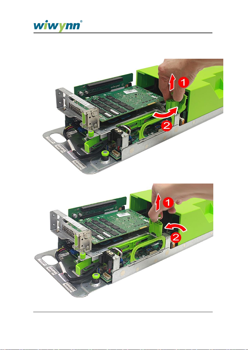
4.1.1 Removing the SV7221G2-S Optional PCIe Card
1 Pull and hold the card stopper knob (1), then rotate the card stopper
clockwise (2).
SV7221G2 Series User Manual 41

2 Pull down the card guide on the PCIe bracket.
42 SV7221G2 Series User Manual
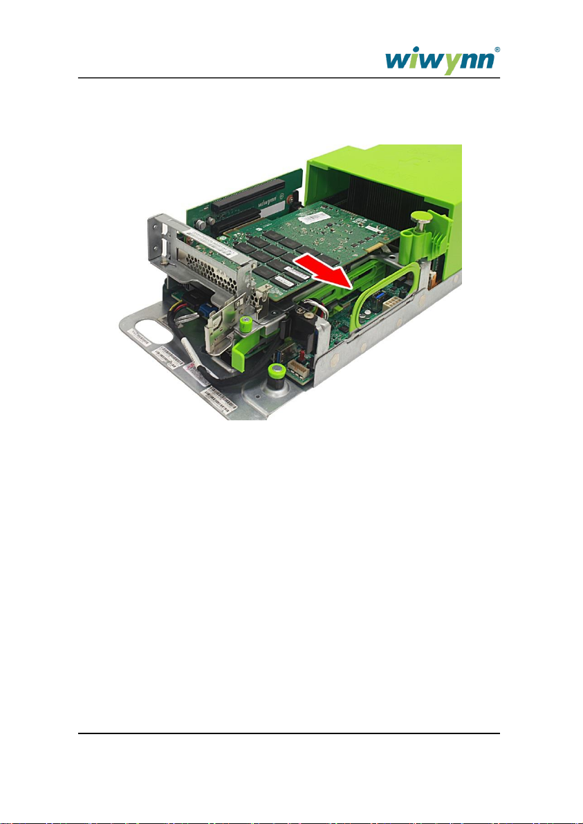
3 Remove the PCIe card from the riser card connector.
SV7221G2 Series User Manual 43

4.1.2 Installing the SV7221G2-S Optional PCIe Card
1 Insert the PCIe card into its slot in the riser card and press until it latches
into place.
44 SV7221G2 Series User Manual

2 Pull up the card guide on the PCIe bracket.
SV7221G2 Series User Manual 45
3 Pull and hold the card stopper knob (1), then rotate the card stopper
counterclockwise (2).
46 SV7221G2 Series User Manual

4.2 Replacing the SV7221G2-V Optional
PCIe Card
4.2.1 Removing the SV7221G2-V Optional PCIe Card
1 Disconnect any cable(s) from the optional PCIe card(s).
2 Loosen the thumbscrew on the PCIe module.
SV7221G2 Series User Manual 47

3 Pull up and remove the PCIe module from the chassis.
4 Remove the screw securing the optional PCIe card to the PCIe module.
48 SV7221G2 Series User Manual

5 Remove the optional PCIe card.
SV7221G2 Series User Manual 49

4.2.2 Installing the SV7221G2-V Optional PCIe Card
1 Insert the optional PCIe card.
2 Tighten the screw to secure the optional PCIe card to the PCIe module.
50 SV7221G2 Series User Manual

3 Lower the PCIe module into the chassis and press until it is securely
seated into the riser card slot.
4 Tighten the thumbscrew to secure the PCIe module to the chassis.
SV7221G2 Series User Manual 51

5 Connect the cable(s) to the optional PCIe card(s).
52 SV7221G2 Series User Manual

4.3 Replacing the SV7221G2-P Optional
PCIe Card
4.3.1 Removing the SV7221G2-P Optional PCIe Card
1 Disconnect any cable(s) from the optional PCIe card(s).
2 Loosen the thumbscrew on the PCIe module.
3 Pull up and remove the PCIe module from the chassis.
SV7221G2 Series User Manual 53

4 Remove the screw (1) and pull out the optional PCIe card (2).
54 SV7221G2 Series User Manual

4.3.2 Installing the SV7221G2-P Optional PCIe Card
1 Insert the optional PCIe card (1) and tighten the screw (2) to secure it to
the PCIe module.
2 Lower the PCIe module into the chassis and press until it is securely
seated into the riser card slot.
SV7221G2 Series User Manual 55

3 Tighten the thumbscrew to secure the PCIe module to the chassis.
56 SV7221G2 Series User Manual

4.4 Replacing the SV7221G2-S Riser Card
4.4.1 Removing the SV7221G2-S Riser Card
1 Perform the "Removing the SV7221G2-S Optional PCIe Card"
procedure on page 41.
2 Press (1) and lift (2) the plastic clasps on the riser card bracket.
3 Lift the plastic clasps (1) to release the riser card bracket (2) from the
chassis.
SV7221G2 Series User Manual 57

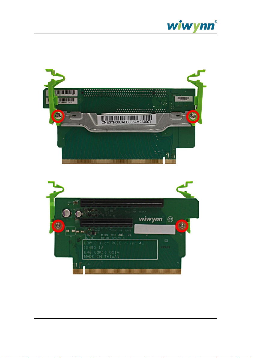
4 Loosen the two screws that secure the riser card to its bracket.
NOTE: When removing the screws on the riser card, make sure you do not
lose the nuts on the front side. Keep these nuts for future
installation.
58 SV7221G2 Series User Manual
4.4.2 Installing the SV7221G2-S Riser Card
1 Secure the riser card to the riser card bracket using two screws and nuts
SV7221G2 Series User Manual 59

2 Insert the riser card with bracket into its slot in the mainboard and press
down until it latches into place.
3 Press (1) and push down (2) the plastic clasps on the riser card bracket.
4 Perform the "Installing the SV7221G2-S Optional PCIe Card"
procedure on page 44.
60 SV7221G2 Series User Manual

4.5 Replacing the SV7221G2-V Riser Card
4.5.1 Removing the SV7221G2-V Riser Card
1 Perform the "Removing the SV7221G2-V Optional PCIe Card"
procedure on page 47.
2 Loosen the two thumbscrews (1) and remove the riser card (2) from the
bracket.
SV7221G2 Series User Manual 61

4.5.2 Installing the SV7221G2-V Riser Card
1 Insert the riser card (1) into the bracket and tighten the two thumbscrews
(2).
2 Perform the "Installing the SV7221G2-V Optional PCIe Card"
procedure on page 50.
62 SV7221G2 Series User Manual

4.6 Replacing the SV7221G2-P Riser Card
4.6.1 Removing the SV7221G2-P Riser Card
1 Perform the "Removing the SV7221G2-S Optional PCIe Card"
procedure on page 53.
2 Loosen the two thumbscrews that secure the riser card to the bracket.
3 Remove the riser card from the bracket.
SV7221G2 Series User Manual 63

4.6.2 Installing the SV7221G2-P Riser Card
1 Insert the riser card into the bracket.
2 Tighten the two thumbscrews.
3 Perform the "Installing the SV7221G2-P Optional PCIe Card"
procedure on page 55.
64 SV7221G2 Series User Manual

4.7 Replacing the SV7221G2-S
Drive and Drive Module
4.7.1 Removing the SV7221G2-S Drive Module
1 Perform the "Removing the SV7221G2-S Optional PCIe Card"
procedure on page 41.
2 Perform the "Removing the SV7221G2-S Riser Card" procedure on
page 57.
3 Disconnect the SATA cable from the mainboard.
SV7221G2 Series User Manual 65

4 Disconnect the power cable from the mainboard.
5 Disconnect the SATA cables from the HDD.
66 SV7221G2 Series User Manual

6 Use both hands to pull the HDD module handles forward.
7 Remove the HDD module by lifting it up by the handles.
SV7221G2 Series User Manual 67

4.7.2 Installing the SV7221G2-S Drive Module
1 Hold the HDD module handles and carefully lower the module. Make
sure the gaps on the module are aligned with the posts inside the
chassis
2 Use both hands to push the HDD module handles.
68 SV7221G2 Series User Manual

3 Connect the SATA cables to the HDD.
4 Connect the power cable to the mainboard.
SV7221G2 Series User Manual 69

5 Connect the SATA cable to the mainboard.
6 Install the SV7221G2-S optional PCIe card (see page 44) and the
SV7221G2-S riser card (see page 59).
70 SV7221G2 Series User Manual

4.7.3 Removing the SV7221G2-S HDD
1 Perform the "Removing the SV7221G2-S Drive Module" procedure on
page 65.
2 Press the stopper on the HDD module (1) and use a flat-blade
screwdriver to push out the HDD (2) from the rear.
3 Pull out the HDD.
SV7221G2 Series User Manual 71

4.7.4 Installing the SV7221G2-S HDD
1 Press the stopper handle on the HDD module (1) and insert the HDD
(2).
2 Push the HDD until the stopper clicks into place.
3 Reinstall the HDD module (see "Installing the SV7221G2-S Drive
Module" procedure on page 68.
72 SV7221G2 Series User Manual

4.8 Replacing the SV7221G2-V Storage
Drives and Drive Module
4.8.1 Removing the SV7221G2-V Storage Drive
1 Press the handle on the 2.5” drive tray (1), then pull out the tray (2).
2 Pull the left or right side rail (1) of the drive tray to withdraw the mounting
pins from the drive. Remove the SSD or HDD (2) from its tray.
SV7221G2 Series User Manual 73

4.8.2 Installing the SV7221G2-V Storage Drive
1 Pull the left and right side rails (1) of the drive tray and insert the SSD or
HDD (2) making sure that the mounting pins on the tray fit into the drive.
2 Insert the drive tray into its slot in the chassis and push until it latches
into place.
74 SV7221G2 Series User Manual

4.8.3 Removing the SV7221G2-V Drive Module
1 Remove the SV7221G2-V PCIe module (see page 47).
2 Remove all drives
3 Disconnect the backplane LED cable and power cable from the
backplane board. Pull out the drive module handles.
SV7221G2 Series User Manual 75

4 Disconnect the SATA cable from the backplane board.
5 Remove the drive module from the chassis.
76 SV7221G2 Series User Manual

4.8.4 Installing the SV7221G2-V Drive Module
1 Lower the drive cage until it is properly seated into the chassis.
2 Connect the SATA cable to the backplane board.
SV7221G2 Series User Manual 77

3 Connect the backplane LED cable and power cable to the backplane
board. Push the drive module handles.
4 Reinstall all drives
5 Install the SV7221G2-V PCIe module (see page 50).
78 SV7221G2 Series User Manual

4.9 Replacing the SV7221G2-P Drives and
Drives Module
4.9.1 Removing the SV7221G2-P Storage Drive
1 Press the handle on the 2.5” drive tray (1), then pull out the tray (2).
2 Pull the left or right side rail (1) of the drive tray to withdraw the mounting
pins from the drive. Remove the SSD or HDD (2) from its tray.
SV7221G2 Series User Manual 79

4.9.2 Installing the SV7221G2-P Storage Drive
1 Pull the left and right side rails (1) of the drive tray and insert the SSD or
HDD (2) making sure that the mounting pins on the tray fit into the drive.
2 Insert the drive tray into its slot in the chassis and push until it latches
into place.
80 SV7221G2 Series User Manual

4.9.3 Removing the SV7221G2-P Drive Module
1 Remove the SV7221G2-P PCIe module (see page 53).
2 Remove all SSD drives
3 Pull out the drive module handles (1) and remove the backplane LED
cable (2) from the backplane board.
SV7221G2 Series User Manual 81

4 Disconnect the SATA cables from the backplane board.
82 SV7221G2 Series User Manual

5 Remove the power cable from the backplane board.
6 Remove the drive module from the chassis.
SV7221G2 Series User Manual 83

4.9.4 Installing the SV7221G2-P Drive Module
1 Lower the drive cage until it is properly seated into the chassis.
2 Connect the power cable to the backplane board.
84 SV7221G2 Series User Manual

3 Connect the SATA cables to the backplane board.
SV7221G2 Series User Manual 85

4 Connect the backplane LED cable (1) and push drive module handles.
5 Re-install the SV7221G2-P PCIe module (see page 55).
86 SV7221G2 Series User Manual

4.10 Replacing the Mezzanine Card
4.10.1 Removing the Mezzanine Card
1 Remove the drive module (see page 65, 73 or 79).
2 Press the latches that secure the mezzanine card to the mainboard.
3 Remove the mezzanine card from the mainboard.
SV7221G2 Series User Manual 87

4.10.2 Installing the Mezzanine Card
1 Align the holes on the mezzanine card with the corresponding retainer
plugs on the mainboard. Press down the mezzanine card gently until the
retainer plugs and latches lock into place.
2 Reinstall the drive module (see page 68, 74 or 84).
88 SV7221G2 Series User Manual

4.11 Replacing the Optional M.2 SSD Card
NOTE: To use the offboard M.2 VGA card as the main display output, set the
Miscellaneous Configuration in BIOS Setup to Offboard Device. You can
only use the iKVM function on the offboard M.2 VGA card if it is not the
main display output.
4.11.1 Removing the Optional M.2 SSD Card
1 Remove the drive module (see page 65, 73 or 79).
2 Pry open the latch that secures the M.2 SSD card to the mainboard.
3 Remove the M.2 SSD card from the mainboard.
SV7221G2 Series User Manual 89

4.11.2 Installing the Optional M.2 SSD Card
1 Insert and press down the M.2 SSD card gently.
2 Lock the latch to secure the M.2 SSD card to the mainboard.
90 SV7221G2 Series User Manual

WARNING
There is a danger of explosion if the battery is
incorrectly replaced. Replace only with the same or
equivalent type recommended by the equipment
manufacturer.
3 Reinstall the drive module (see page 68, 74 or 84).
4.12 Replacing the RTC Battery
4.12.1 Removing the RTC Battery
1 Remove the drive module (see page 65, 73 or 79).
2 Use a flat blade screwdriver to disengage the battery (1) from its holder,
then lift the RTC battery (2) off the mainboard.
SV7221G2 Series User Manual 91

92 SV7221G2 Series User Manual

4.12.2 Installing the RTC Battery
1 Gently insert the RTC battery (1) on its holder and push sideways (2)
until it latches into place.
2 Reinstall the drive module (see page 68, 74 or 84).
SV7221G2 Series User Manual 93
4.13 Replacing the System Cover
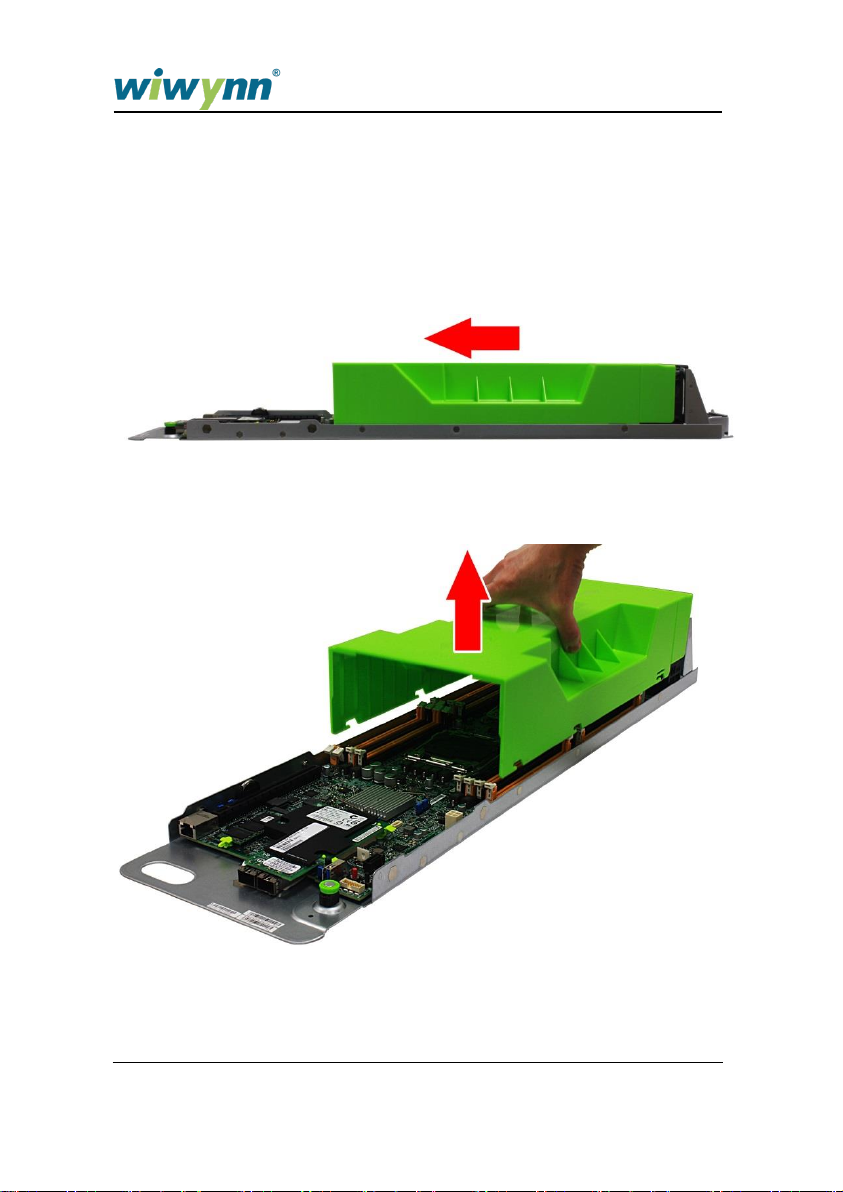
4.13.1 Removing the System Cover
1 Slide the cover toward the front of the system to disengage the latches
that secure the cover to the chassis.
2 Lift the cover off the chassis.
94 SV7221G2 Series User Manual

4.13.2 Installing the System Cover
1 Lower the system cover into the chassis.
2 Push towards the rear of the system until the cover latches into place.
SV7221G2 Series User Manual 95

4.14 Replacing the System Fan
4.14.1 Removing the System Fan
1 Perform the "Removing the System Cover" procedure on page 94.
2 Disconnect the fan cable from the mainboard.
3 Pull out the system fan from the chassis.
4 Repeat the steps above to remove the other fan.
96 SV7221G2 Series User Manual

4.14.2 Installing the System Fan
1 Insert the system fan into the chassis.
2 Make sure the posts on the fan are properly fitted into the notches.
SV7221G2 Series User Manual 97

3 Connect the fan cable to the mainboard.
4 Reinstall the system cover (see "Installing the System Cover"
procedure on page 95).
98 SV7221G2 Series User Manual

4.15 Replacing the Memory Modules
4.15.1 Removing the Memory Module
1 Perform the "Removing the System Cover" procedure on page 94.
2 Open the locking clips (1) that secure the memory module. Gently pull
the DIMM upward (2) to remove it from the mainboard.
SV7221G2 Series User Manual 99

4.15.2 Installing the Memory Modules
1 Insert the memory module into the DIMM slot (1), then push downward
until the locking clips lock (2) into place.
2 Reinstall the system cover (see "Installing the System Cover"
procedure on page 95).
100 SV7221G2 Series User Manual
 Loading...