

Page 1

G
S
G
S
M
M
V
V
OII
O
P
P
Gaattee
G
waayy
w
User Manual
Seerriieess
S
Page 2
GSM VOIP Gateway Series
GSM VOIP Gateway Series
1. OVERVIEW
1.1 Introduction
The GSM VOIP Gateway is a broadband relay gateway newly developed by
VinTelecom Technology. It is a new product for seamless connection between
the GSM network and VoIP network. When the mobile phone SIM card is
installed in the GSM VOIP Gateway, users can register the GSM phone to the
VoIP softswitch system. Through the GS M VOIP Gateway, users can realize the
uplink and downlink call s between the GSM network and the VoIP network. In
addition, the GSM VOIP Gateway supports the transparent tra nsmission of the
call er number from the PSTN to the VoIP. The
GSM VOIP Gateway features embedded SIP and H.323 protocols with flexible
setting. The bi-directional password authentication (call authorization) and trust
list authentication greatly minimize the risk of charge losses and the flexible
routing function can meet special requirements of various call forwarding. In
particular, the GSM VOIP Gateway supports multi device groups, with flexible
setting of large GSM gateway groups with different channel numbers. With its
low price, excell ent voice quali ty, and powerful features, the GSM VOIP
Gateway is the first choice for system in tegrators, traffic operators, and softswi t
ch manufacturers.
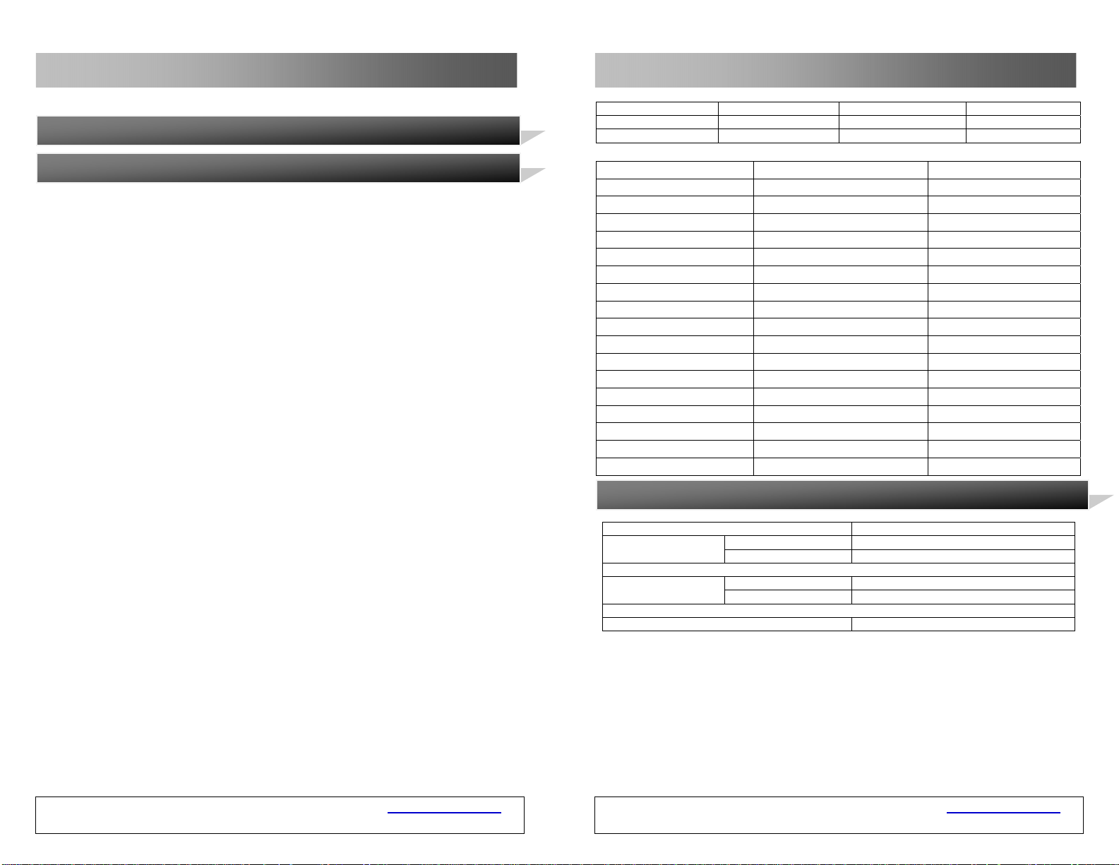
The GSM VOIP Gateway includes WT-2201, WT-2204 and WT-2208.
Color Gray Gray
VoIP Channel 1 4
GSM Channel 1 4
Hardware Parameter Remark
Model WT-2208 Customized
Processor ARM9E 133Mhz
DSP VPDSP101 95Mhz 2 pieces
RAM 16M
FLASH 4M
Power DC12V/3A±10% Input 100V to 240V
GSM Band Default 900M/1800M Default
Optional 850/1900M Customized
Power Consumption Max. 20W
LED RUN, GSM, LAN, PC
Network Adapter 2 100/10BASE-T
Weight 1.204Kg Without AC Adapter
Operating Temperature 0-40°C
Operating Humidity 40%-90% Not Congealed
Color Gray
VoIP Channel 8
GSM Channel 8
5 Factory Default Parameter Table
Network
Password
Parameter Default Value
LAN Dynamic IP (DHCP)
PC Fixed IP 192.168.8.1
Admin Admin
user 1234
Default Time Zone GMT+8
GSM VOIP Gateway USER MANUAL – Rev1 – Technical Support: [email protected]
COPYRIGHT ©2011 WITURA CORPORATION SDN BHD
2
GSM VOIP Gateway USER MANUAL – Rev1 – Technical Support: [email protected]
COPYRIGHT ©2011 WITURA CORPORATION SDN BHD
75
Page 3
GSM VOIP Gateway Series
GSM VOIP Gateway Series
Select Tool > Reset to restart the GSM VOIP Gateway .
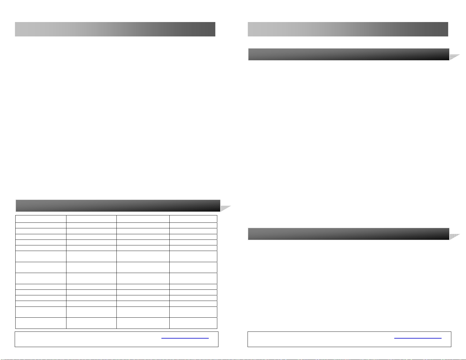
4 Parameters Of Equipment
Hardware Feature Parameter Parameter Remark
Model WT-2201 WT-2204 WT-2208
Processor ARM9E 133Mhz ARM9E 133Mhz
DSP VPDSP101 95Mhz VPDSP101 95Mhz 2pcs
RAM 16M 16M
FLASH 4M 4M
Power DC12V/2A ±10% DC12V/2A ±10% Input 100V to
GSM Band Default
Optional
Power Consumption Max. 5W Max. 12W
LED RUN, GSM, LAN, PC RUN, GSM, LAN, PC
Network Adapter 2 2 100/10BASE-T
Weight 0.10KG 0.45KG Without
Operating
Temperature
Operating Humidity 40%-90% Not
GSM VOIP Gateway USER MANUAL – Rev1 – Technical Support: [email protected]
900M/1800M
850/1900M
0-40°C 0-40°C
Congealed
COPYRIGHT ©2011 WITURA CORPORATION SDN BHD
Default
900M/1800M
Optional
850M/1900M
40%-90% Not
Congealed
240V
Default
Customized
74
1.2 Protocols
TCP/ IP V4 (IPV6 Automatic Adaptive)
ITU-T H.323 V4 standard
H.2250 V4 standard
H.245 V7 standard
H.235 standard (MD5, HMAC-SHA1)
ITU-T G.711 Alaw/ULaw, G.729A, G.729AB, G.723.1 and GSM voice coding
RFC1889 real-time digital transmission protocol
Firewall penetration technology
SIP V2.0 standard
STUN
Network management protocol (NMP)
PPPoE
PPP authentication protocol (PAP)
Internet control message protocol (ICMP)
TFTP agent protocol
Hypertext transfer protocol (HTTP)
Dynamic host configuration protocol (DHCP)
Domain name system (DNS)
User account authentication (via MD5)
Out-band DTMF relay: RFC 2833 and SIP INFO
1.3
ARM9E high-speed processor
Voice coding and voice digital signal processor
Two 10/100MB Ethernet ports that support the IEEE 802.3 standard and
PC
LED that dis plays the status of Ethernet ports
Ethernet cable
SIM card that supports the GSM 900M/1800M and GSM 850M/1900M bands
Hardware Feature
connect the LAN and
GSM VOIP Gateway USER MANUAL – Rev1 – Technical Support: [email protected]
COPYRIGHT ©2011 WITURA CORPORATION SDN BHD
3
Page 4
GSM VOIP Gateway Series
GSM VOIP Gateway Series
1.4 Software Feature
LINUX OS
Embedded HTTP that accesses internal parameters
PPPoE diali ng
NAT broadband routing function
DHCP cli ent
DHCP server
Software online upgrade
Automatic call ing
Supporting multiple languages
Supporting outgoing SMS calls
1.5 Product Package List
1) A GSM VOIP Gateway
2) 12V/2A DC(For WT-2204) or 12V/3A DC (For WT-2208) transformer
3) An Ethernet cable (2 m)
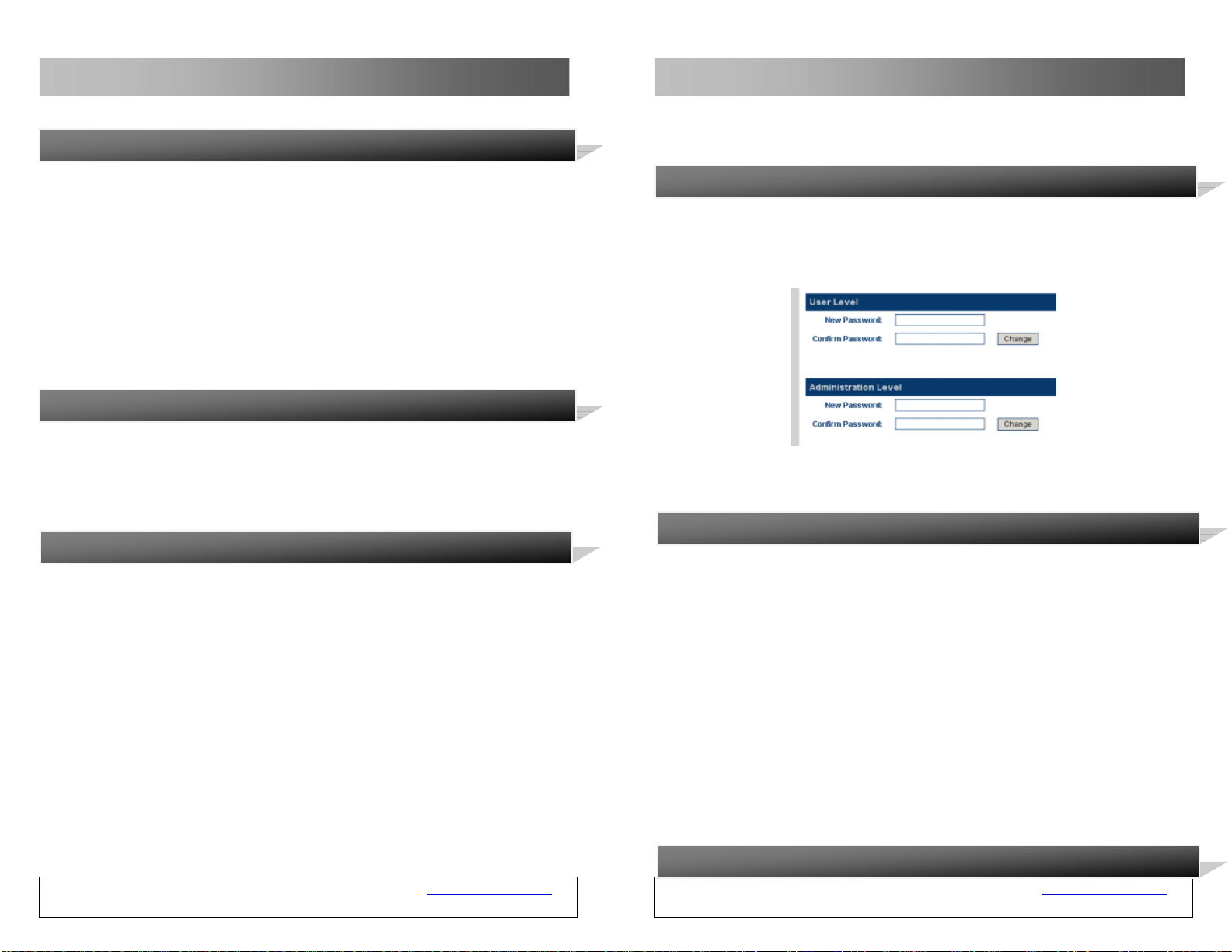
1.6 Product Appearance
Note: During the upgrading, do not cut off the power. Otherwise, the GSM VOIP
Gateway will be damaged.
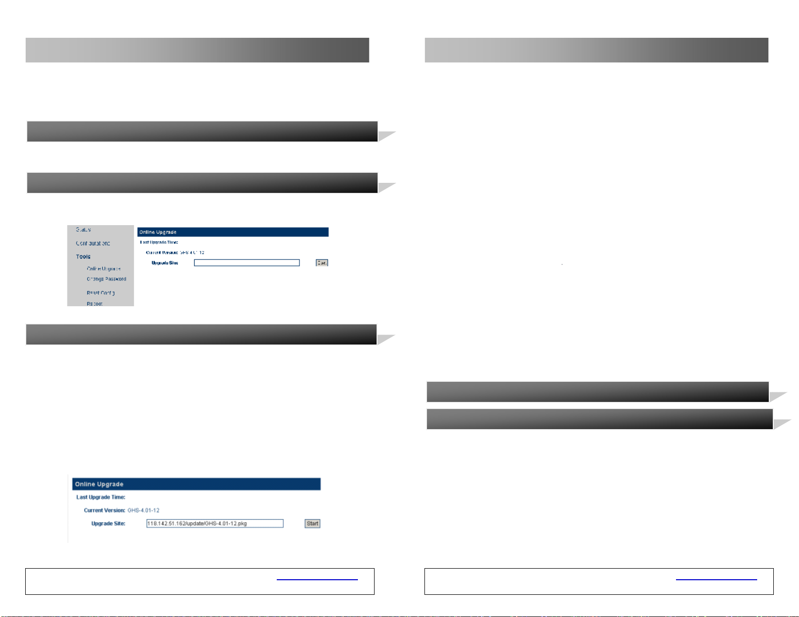
3.13.2 Modification of Password
You can modify the password of the user and administrator. Select Tool > Modify
Password. The password modification page is displayed, as shown in th e following
figure. Enter a new password and click “Change”. Then, the password is
successfully modified.
Note: The password modified by users wil l be cleared and restored to th e factory
default password after the factory settings are restored.
3.13.3 Restore Factory Settings
Select Tool > Restore Factory Settings. The following prompt is displayed.
Click OK. All the parameters of the gateway will be clear ed and the gateway will
GSM VOIP Gateway USER MANUAL – Rev1 – Technical Support: [email protected]
COPYRIGHT ©2011 WITURA CORPORATION SDN BHD
4
automatically restart. After the gateway is restarted, all the settings restore to
the factory default settings. This feature can be comp leted by using the asterisk
command. For details about this operation, see the section of “Asterisk
Instructions”.
3.13.4 Reset
GSM VOIP Gateway USER MANUAL – Rev1 – Technical Support: [email protected]
COPYRIGHT ©2011 WITURA CORPORATION SDN BHD
73
Page 5
GSM VOIP Gateway Series
Note: Some of parameters of the gateway wil l not be valid until the gateway is
restarted. Therefore, you are advised to res tart the gatewa y after the parame ters
are modified, so that the modification can take effect.
3.12 Abandon the change
When the new setting is not saved, you can clear all the unsaved parameters.
3.13 Tool
Select Menu > Tool. The following page is displayed.
GSM VOIP Gateway Series
3.13.1 Online Upgrading
Warning! Only experienced users and administrators can implement the online
upgrading.
Select Tool > Online Upgrading. The online upgrading page is displayed, as shown
in the following figure. Enter the complete name and path of the upgrade package,
such as http://118.142.51.162/update/GHS-4.01-12.pkg, and then click “Start”.
The gateway begins to upgrade. After the GSM VOIP Gateway is successfully
upgraded, the gateway will automatically restart.
1) LAN - The network input port t hat is connected to the router, Mode m, and
switch
2) PC - The network output port that is connected to network sharing
equipment (less than 100 terminals)
3) DC4.5V/2ADC - The output terminal that connects the transformer
equipped with delivery
4) Reset - The reset switch for quick restart of the GSM VOIP Gateway
2
2.1 Installation Procedure
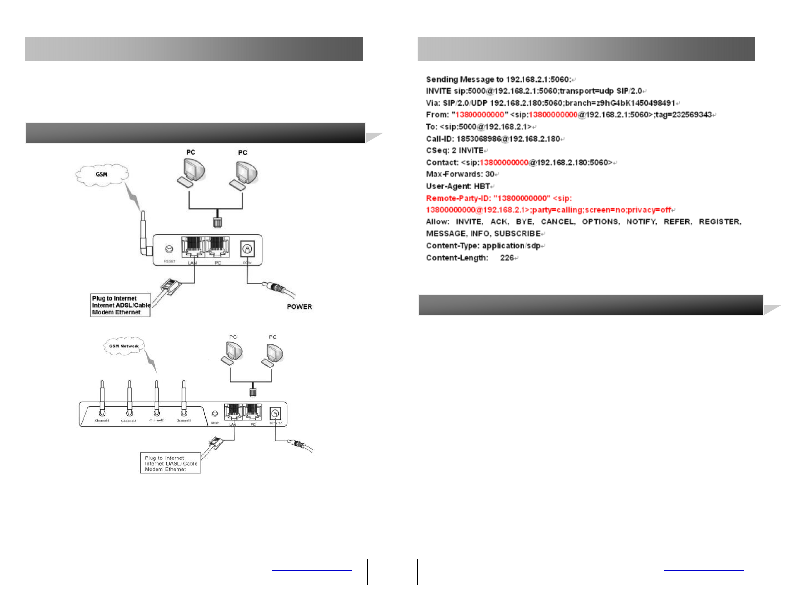
The GSM VOIP Gateway has 1/8 SIM card slots, an LAN port, and a PC port.
The install ation procedure is as follows:
1. Open the bottom cover of the GSM VOIP Gateway and in sert an SIM card
2. Connect the LAN port with the upper-layer network equipment with the
Installation
of the local GSM network
Ethernet cable
GSM VOIP Gateway USER MANUAL – Rev1 – Technical Support: [email protected]
COPYRIGHT ©2011 WITURA CORPORATION SDN BHD
72
GSM VOIP Gateway USER MANUAL – Rev1 – Technical Support: [email protected]
COPYRIGHT ©2011 WITURA CORPORATION SDN BHD
5
Page 6
GSM VOIP Gateway Series
3. PC port supports network sharing, so connect the PC port to the co mputer
or lower-layer switch (HUB or router)
4. Connect the output terminal of the transformer with the power port.
2.2 Connection Figure
GSM VOIP Gateway Series
3.11
After setting is changed, click “Save” and the new setting will be valid. O therwise,
the new setting is invalid.
Save the Change
GSM VOIP Gateway USER MANUAL – Rev1 – Technical Support: [email protected]
COPYRIGHT ©2011 WITURA CORPORATION SDN BHD
6
GSM VOIP Gateway USER MANUAL – Rev1 – Technical Support: [email protected]
COPYRIGHT ©2011 WITURA CORPORATION SDN BHD
71
Page 7
GSM VOIP Gateway Series
SIP Terminal
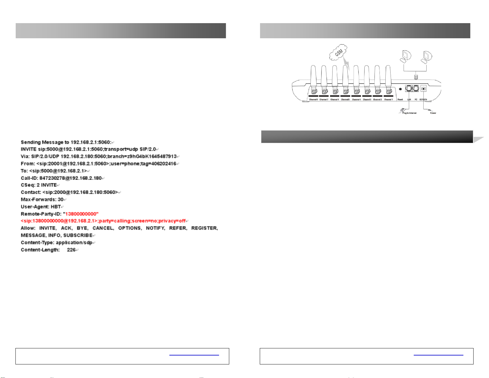
Disable: It’s not all owed to transfer the PSTN caller number to the VoIP system;
Enable: The CID is set as the SIP caller number.
Use Remote Party ID: The GSM VOIP Gateway will add the PSTN caller number
to the call request signaling of the VoIP system. The signaling is as follows
(provided that the PSTN caller number is 13800000000):
GSM VOIP Gateway Series
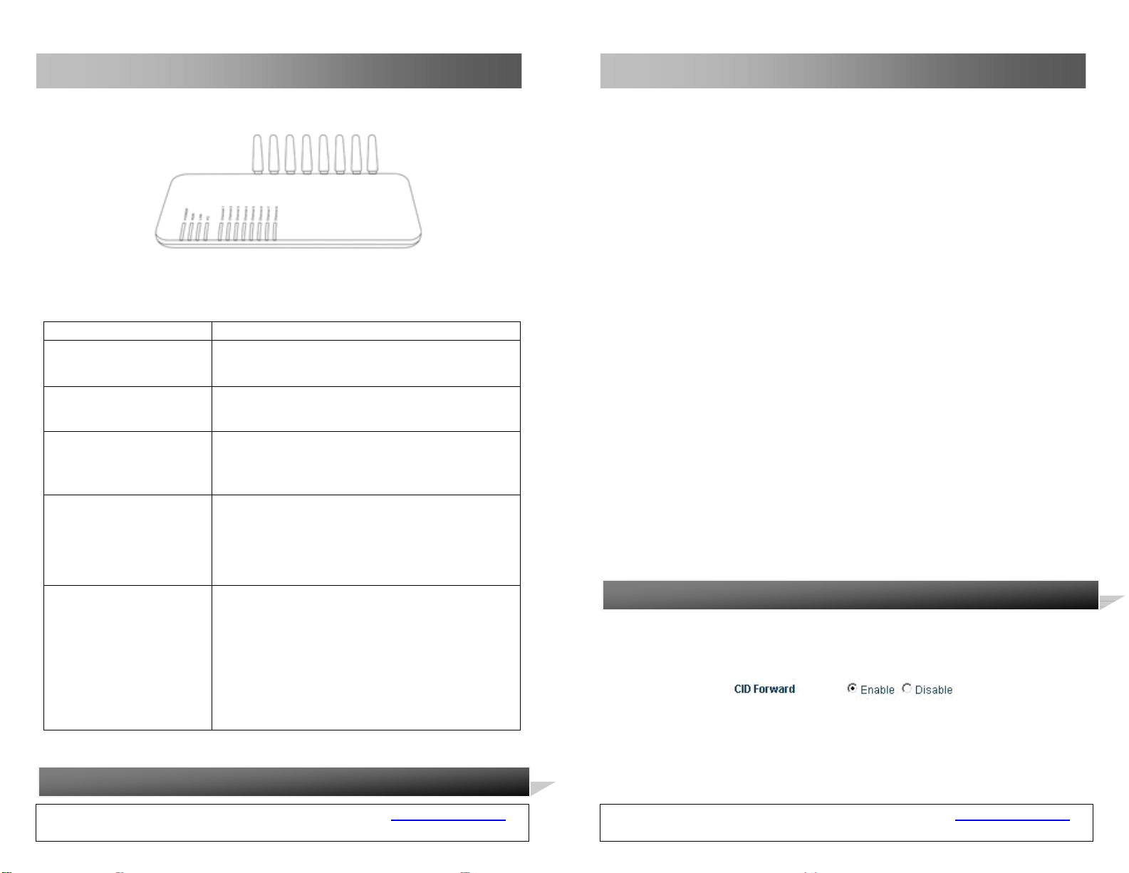
2.3 LED Indicators
Use CID as SIP caller number: The GSM VOIP Ga teway directly initiates the
call request to the VoIP system through the PSTN caller number and adds the
relevant information to Remote Par ty ID option of the request signaling . The call
request signaling is as follows:
GSM VOIP Gateway USER MANUAL – Rev1 – Technical Support: [email protected]
COPYRIGHT ©2011 WITURA CORPORATION SDN BHD
70
GSM VOIP Gateway USER MANUAL – Rev1 – Technical Support: [email protected]
COPYRIGHT ©2011 WITURA CORPORATION SDN BHD
7
Page 8
GSM VOIP Gateway Series
The description of LED indicators is as follows
LED Description
Power indicator
LAN indicator
PC indicator
RUN indicator
Channel indicator
2.4 SMS Instructions
GSM VOIP Gateway USER MANUAL – Rev1 – Technical Support: [email protected]
COPYRIGHT ©2011 WITURA CORPORATION SDN BHD
Power indicator This indicator is constantly ON
after connected with power
This indicator is ON after connected with the
network equipment
This indicator is ON after connected with the
network equipment and blinks during data
transmission.
1. The RUN indicator blinks once every 100ms
during startup.
2. When GSM VOIP Gateway is connected with
the server, the RUN indicator bli nks once per
second.
1. When the GSM module of the GSM VOIP
Gateway logs onto the local GSM2.
2. When this indicator blinks quickly, it indicates
that the GSM VOIP Gateway is trying to log
onto the local GSM network.
3. When the GSM channel of the GSM VOIP
Gateway is activated, this indicator is normally
ON.
8
GSM VOIP Gateway Series
To: <sip:[email protected]>
Call-ID: [email protected]
CSeq: 3MESSAGE
Contact: <sip:[email protected]>
max-forwards: 16
date: Tue, 18 Nov 2008 06:36:37 GMT
user-agent: SIPPER for 3CX Phone
p-hint: usrloc applied
Content-Type: text/plain
Content-Length: 26
13682626800
Hello world
Note: The SMS forwarding mode of the GSM VOIP Gateway is only functional
under the SIP protocol.
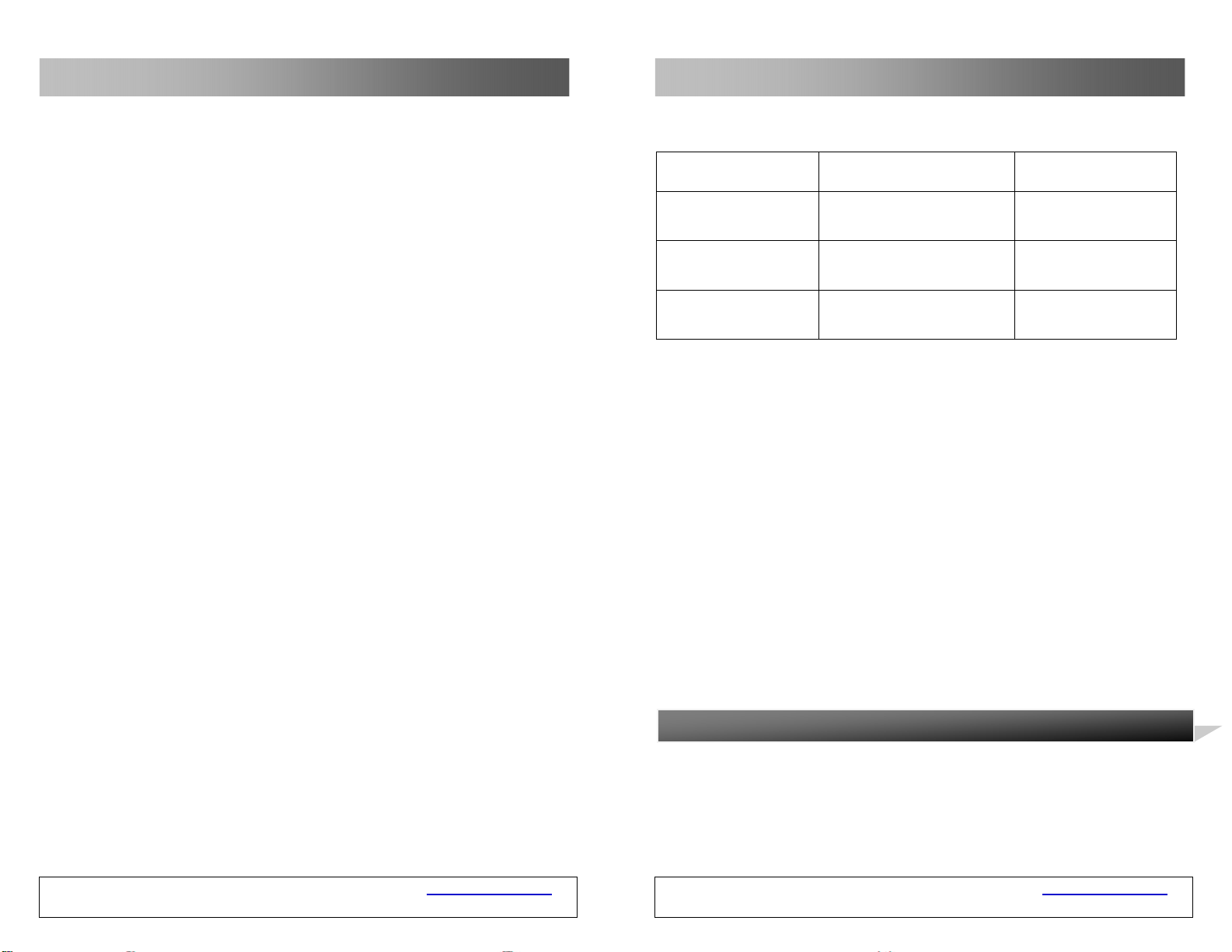
3.10 Transparent Transmission of PSTN Caller Numbers
The GSM VOIP Gateway permit s the transparent transmission of PSTN call er
numbers to the VoIP system in various methods.
H323 Terminal
GSM VOIP Gateway USER MANUAL – Rev1 – Technical Support: [email protected]
COPYRIGHT ©2011 WITURA CORPORATION SDN BHD
69
Page 9
GSM VOIP Gateway Series
GSM VOIP Gateway Series
The following is an example that the GSM V OIP Gateway forwards the SMS to the
SIP 3999. The red part is the content of the SMS.
MESSAGE sip:[email protected] SIP/2.0
Via: SIP/2.0/UDP 192.168.2.162:5060;branch=z9hG4bK1967685528
From: <sip:[email protected]>;tag=667435795
To: <sip:[email protected]>
Call-ID: [email protected]
CSeq: 4MESSAGE
Contact: <sip:[email protected]:5060>
Max-Forwards: 30
User-Agent: H
Content-Type: text/plain
Content-Length: 28
8613682626865
075583185700
2. The SMS sent to the GSM VOIP Gateway from the SIP is forwarded to the
specified PSTN number.
The following example is about the Hello world sent from SIP 3999 to
13682626800. Where, in the content of the SIP message (in red), the first li ne
indicates the number to receive th e SMS. The s econd line ind icates the c ontent of
the SMS.
MESSAGE sip:[email protected]:5060 SIP/2.0
From: <sip:[email protected]>;tag=5031
GSM VOIP Gateway USER MANUAL – Rev1 – Technical Support: [email protected]
COPYRIGHT ©2011 WITURA CORPORATION SDN BHD
68
Users can send instructions to the GSM VOIP Gateway through the SMS.
Function Instructions
(Short message content)
Obtain information
from the LAN port
Reset the GSM VOIP
Gateway setting
Reboot the GSM VOIP
Gateway
1) When “info” or “INFO” is sent to the GSM VOIP Gateway through SMS, the
GSM VOIP Gateway will return immediately the LAN por t info to the mobile
phone.
2) When performing reset/reboot through the SMS, the password
authentication is required. The password is identical with that of the ad min.
The detail ed procedure is as follows:
a. The keyword “reset” and “reboot” is case insensitive, but the password
is case sens itive .
b. When the reset instruction is sent, the GSM VOIP Gateway will
automatically reboot.
To perform reset, the admin password of GSM VOIP Gateway user is
“tengda”. Input “reset tengda” or “RESET tengda” in the SMS to reset.
To perform reboot, the admin password of GSM VOIP Gateway user is
“tengda”. Input “reboot tengda” or “REBOOT tengda” in the SMS to reboot.
3.
Before setting the page, you need to have the IP address of the PC port of the
gateway first. Connect the computer for setting t he gateway to th e PC port of the
GSM VOIP Gateway. The GSM VOIP Gateway has a built-in page server that is
used to accept or obtain the HTTP. You can set the related functions for the GSM
VOIP Gateway through the Internet Explorer.
Page Settings
GSM VOIP Gateway USER MANUAL – Rev1 – Technical Support: [email protected]
COPYRIGHT ©2011 WITURA CORPORATION SDN BHD
INFO or info Case insensitive
RESET Password
REBOOT Password
Remark
The keyword RESET is
case insensitive.
The keyword REBOOT
is case insensitive.
9
Page 10
GSM VOIP Gateway Series
3.1 Page Setting Menu
You can access the setting page of the GSM VOIP Gateway through the IP
address of the LAN port or PC port. The default factory settings are as follows:
A: The LAN port supports the DHCP (dynamic IP address). Users can dial the
SIM card number of the gateway and if connected dial *00 to obtain the IP
address.
B: The default IP address and mask of the PC port are 192.168.8.1 and
255.255.255.0 respectively.
Enable the DHCP service of the PC port.
Connect the computer with the PC port of the gateway thro ugh the IP address o f
the PC port, and set the IP of the computer to dynamic IP or fixed IP as
192.168.8.xxx and the default gateway as 192.168.8.1.
Open the Internet Explorer and enter 192.168.8.1 or http://192.168.8.1 in the
address bar, then, the login page is popped up for password input. Enter the
login account (“admin” as default) in the User Na me, and password (“admin” as
default) in the Password field.
GSM VOIP Gateway Series
canMapAlias = FALSE
callIdentifier = {
guid = 16 octets {
cb 40 a4 af 8e 9b 60 96 6b 5f a0 03 f2 ed 55 5b .@....`.k_....U[
}
}
gatekeeperIdentifier = "GnuGk"
willSupplyUUIEs = FALSE
}
3.9.3 SMS Forwarding
The GSM VOIP Gateway supports the SMS forwarding through the SMS under SIP
protocol. After users send the short message to the GSM VOIP Gateway through
the SMS, the GSM VOIP Gateway will send the short message to the specified
VoIP number automatically.
As shown in the above figure, select SMS Mode > Forwarding and enter the VoIP
number that is used to receive the SMS information. The VoIP will automatically
forward all the SMS information from the GSM network to this VoIP number.
Similarly, the GSM VOIP Gateway will automatically forward all the SMS
information from the VoIP to the specified GSM mobile phone.
1. The GSM VOIP Gateway forwards the SMS from the GSM to a specified SIP
number.
GSM VOIP Gateway USER MANUAL – Rev1 – Technical Support: [email protected]
COPYRIGHT ©2011 WITURA CORPORATION SDN BHD
10
GSM VOIP Gateway USER MANUAL – Rev1 – Technical Support: [email protected]
COPYRIGHT ©2011 WITURA CORPORATION SDN BHD
67
Page 11
GSM VOIP Gateway Series
[0] = dialedDigits "9998675588228822"
}
srcInfo = 2 elements {
[0] = dialedDigits "20001"
[1] = h323-ID "20001"
}
srcCallSignalAddress = ipAddress {
ip = 4 octets {
c0 a8 02 ed ....
}
port = 2049
}
bandWidth = 2048
callReferenceValue = 7502
conferenceID = 16 octets {
7f f3 78 77 49 3f 4c c1 9a dc 6a 84 12 d8 30 8f ..xwI?L...j...0.
}
activeMC = FALSE
answerCall = FALSE
GSM VOIP Gateway USER MANUAL – Rev1 – Technical Support: [email protected]
COPYRIGHT ©2011 WITURA CORPORATION SDN BHD
66
GSM VOIP Gateway Series
Click “OK” button and the gateway status page is displayed as default
WT-2201 Status Interface
GSM VOIP Gateway USER MANUAL – Rev1 – Technical Support: [email protected]
COPYRIGHT ©2011 WITURA CORPORATION SDN BHD
11
Page 12
GSM VOIP Gateway Series
WT-2204 Status Interface
GSM VOIP Gateway Series
activeMC = FALSE
answerCall = FALSE
canMapAlias = FALSE
callIdentifier = {
guid = 16 octets {
cb 40 a4 af 8e 9b 60 96 6b 5f a0 03 f2 ed 55 5b .@....`.k_....U[
}
}
gatekeeperIdentifier = "GnuGk"
willSupplyUUIEs = FALSE
}
When the user enters an SMS dial prefix, such as 999, the above call request
signaling is changed to:
Send RAS Message: admissionRequest
admissionRequest {
WT-2208 Status Interface
The GSM VOIP Gateway adopts the tree structure. The menu is on the left and
the setting parameters are on the right, as s ho wn in the above figure.
GSM VOIP Gateway USER MANUAL – Rev1 – Technical Support: [email protected]
COPYRIGHT ©2011 WITURA CORPORATION SDN BHD
12
requestSeqNum = 241
callType = pointToPoint NULL
endpointIdentifier = "3705_endp"
destinationInfo = 1 elements {
GSM VOIP Gateway USER MANUAL – Rev1 – Technical Support: [email protected]
COPYRIGHT ©2011 WITURA CORPORATION SDN BHD
65
Page 13
GSM VOIP Gateway Series
GSM VOIP Gateway Series
callType = pointToPoint NULL
endpointIdentifier = "3705_endp"
destinationInfo = 1 elements {
[0] = dialedDigits "8675588228822"
}
srcInfo = 2 elements {
[0] = dialedDigits "20001"
[1] = h323-ID "20001"
}
srcCallSgnalAddress = ipAddress {
ip = 4 octets {
c0 a8 02 ed ....
}
port = 2049
}
bandWidth = 2048
callReferenceValue = 7502
conferenceID = 16 octets {
7f f3 78 77 49 3f 4c c1 9a dc 6a 84 12 d8 30 8f ..xwI?L...j...0.
}
GSM VOIP Gateway USER MANUAL – Rev1 – Technical Support: [email protected]
COPYRIGHT ©2011 WITURA CORPORATION SDN BHD
64
You can also access the setting page of the GSM VOI P Gateway through the IP
address 192.168.2.216 or 192.168.2.172 of the LAN port of the gateway. The
login method is the same as that o f the PC port, b ut you mu st first obta in the IP
address of the LAN port.
3.2 Status
The status page contains the following contents, as shown in the above figure
3.2.1 Telephone Information
A. Product Sequence Number
Each GSM VOIP Gateway has a factory set sequence number, such as
GOIP08030031, which is used for centralized setting, technical support, and
maintenance filing. The sequence number is printed on the bottom plate of the
gateway and is read-only.
B. Software Version
It displays the current version of software used by the GSM VOIP Gateway. When
you want to upgrade the software, make sure the update versio n is n ew er tha n the
current version.
C.
It displays the current hardware version of the gateway.
D. Line Register Status
It displays the login status of the l ine. W h en the l ine has logged into the SIP server
or H.323 Gatekeeper, LOGIN is displayed, otherwise, LOGOUT is displayed.
E. Line Use Status
It displays the use status of the line. When the line is in use, the status is ACTIVE,
when the line is idle, the status is IDLE.
3.2.2 Network Information
Hardware Version
GSM VOIP Gateway USER MANUAL – Rev1 – Technical Support: [email protected]
COPYRIGHT ©2011 WITURA CORPORATION SDN BHD
13
Page 14
GSM VOIP Gateway Series
GSM VOIP Gateway Series
A. LAN Port
It displays the current IP address of the LAN port, such as 192.168.2.172.
B. PC Port
It displays the current IP address of the PC port.
C. PPPoE Dialing
It displays the PPPoE broadband connection condit ion. Afte r the connection, the
IP address obtained is displayed on the LAN po rt.
D. Default Route
It displays the current gateway address.
E. Domain Name Server (DNS)
It displays the current DNS address.
3.3 User Options
Click “User Options” and the following figure shows.
User Options of the WT-2201
Examples of SMS Dialing:
In the following SMS dialing examples, the H.323 number of the GSM VOIP
Gateway is set as follows:
Mode 2:
When a short message of “8675588228822” is sent from the mobile phone
number (+86)13800000000 to the GSM VOIP Gateway, the GSM VOIP Gateway
will send the following call requests. Whe n the GSM VOIP Gateway sends a call
request through the H.323 number of the GSM VOIP Gateway, the GSM VOIP
Gateway will automatically add the numbe r of the short message sender to the
PSTN Forwarding Number in Call Forwarding (VoIP Incoming Ca ll , Forwarding to
the PSTN Immediately);
In this mode, when the GSM VOIP Gateway receives the call from the H.323 GK,
the GSM VOIP Gateway will forward the call to the short message sending
equipment through the GSM network.
The call request signaling in this mode is as follows:
Send RAS Message: admissionRequest
admissionRequest {
requestSeqNum = 241
GSM VOIP Gateway USER MANUAL – Rev1 – Technical Support: [email protected]
COPYRIGHT ©2011 WITURA CORPORATION SDN BHD
14
GSM VOIP Gateway USER MANUAL – Rev1 – Technical Support: [email protected]
COPYRIGHT ©2011 WITURA CORPORATION SDN BHD
63
Page 15
GSM VOIP Gateway Series
Content-Length: 226
3.9.2 SMS Dialing under the H.323 Protocol
The GSM VOIP Gateway permits users to dial back through the SMS under the
H.323 protocol. After users send the called number to the GSM VOIP Gateway
through the SMS, the GSM VOIP Gateway will send a call request to the H.323 GK
automatically. Users who need thi s function shal l choose t he follow ing parame ters:
Select SMS Mode > Dial and the following page is displayed.
The GSM VOIP Gateway supports three types of outgoing call via SMS:
A: Mode 1 (The current version of the H.323 protocol does not support
this mode, but the later version will. )
In this mode, the GSM VOIP Gateway sets the number of the short message
sender as the calling number of the call and the called number as the short
message content;
B: Mode 2
In this mode, the GSM VOIP Gateway sets the H.323 number of the GSM VOIP
Gateway as the calling number of the call and the called number as the short
message content;
C: Mode 3 (The current version of the H.323 protocol does not support
this mode, but the later version will. )
In this mode, the GSM VOIP Gateway sets the H.323 number of the GSM VOIP
Gateway as the calling number of the call and the called number as the short
message content and the number of the short mes sage sender, whose format is
short message content*the number of the short message sender.
D: SMS Dial Prefix
When the GSM VOIP Gateway initiates the SMS call, the GSM VOIP Ga teway will
change the prefix number to the called number prefix.
GSM VOIP Gateway USER MANUAL – Rev1 – Technical Support: [email protected]
COPYRIGHT ©2011 WITURA CORPORATION SDN BHD
62
GSM VOIP Gateway Series
User Options of the WT-2204/ WT-2208
3.3.1 Language
To select a language, refresh the page to enter th e language page required. For
example, the current language is simplif ied Chinese. If you wish to display the
page in English, click “English” in the menu. After your terminal is restarted, all
the pages will be displayed in Engli sh.
You can also use other languages for setting, as shown in the following figure
Click “English” on the upper right corner of the setting page. Then, th e setting
page will display all info in English. But the shor tcut w il l no t cha nge t he langua g e
of the setting page when logged in next time.
GSM VOIP Gateway USER MANUAL – Rev1 – Technical Support: [email protected]
COPYRIGHT ©2011 WITURA CORPORATION SDN BHD
15
Page 16
GSM VOIP Gateway Series
GSM VOIP Gateway Series
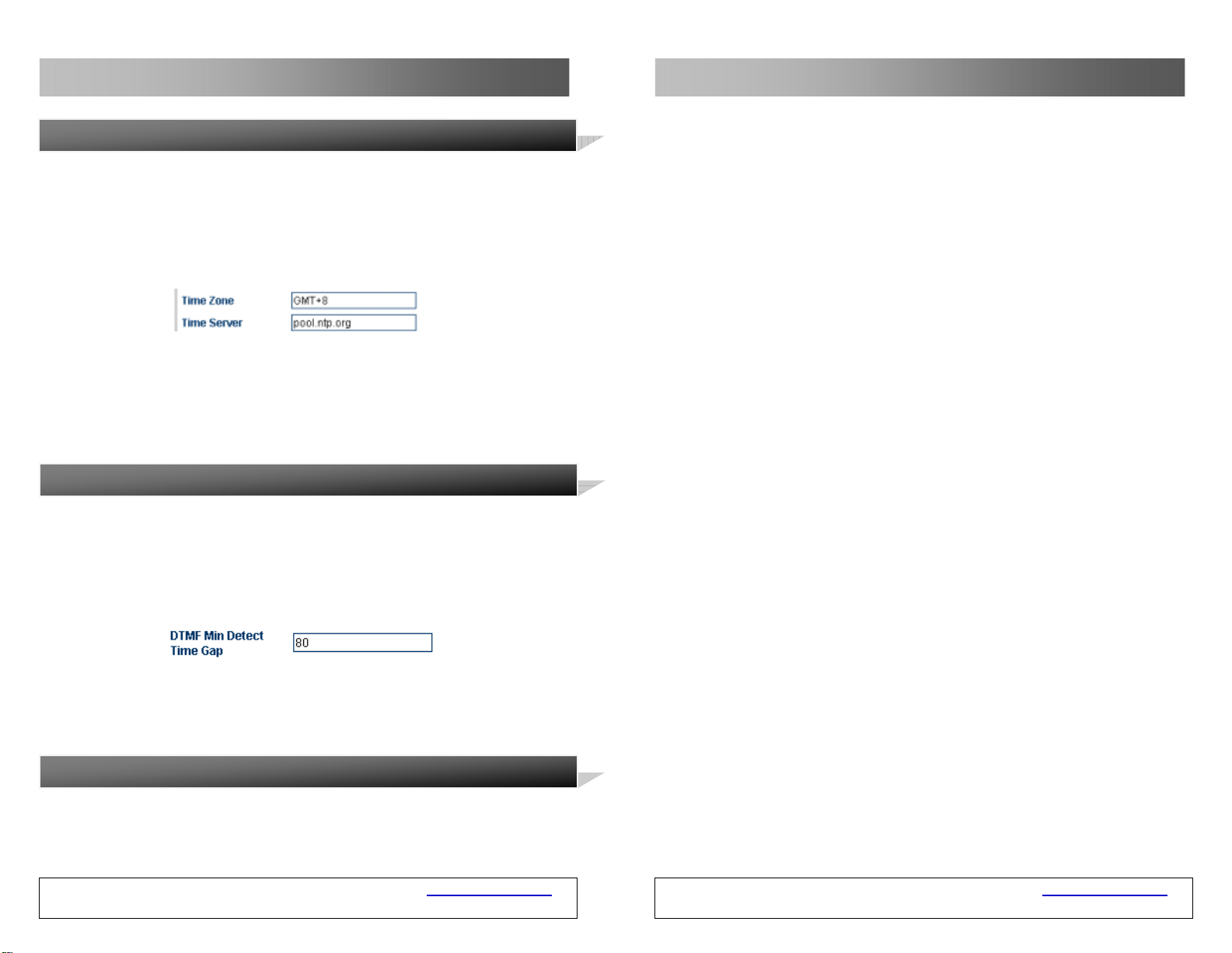
3.3.2 Time Zone and Time Server
This item displays the adjusted time according to the selected time zone. The
gateway receive time and date information from the server through the Network
Time Protocol and the time difference will l be automatically adjusted. For
example, the pacific standard time (PST) is GMT-8 and the pacific daylight ti me
(PDT) is GMT-7.
The time zone indicates the zone where th e gateway is used. You need to enter
the correct time zone, so that the time of the caller ID a nd charging information
can be displayed correctly. The time server is the address of the server that
obtains the network time through the Internet. The default time server is
timekeeper.isi.edu.
3.3.3 DTMF Minimum Detection Interval
This parameter is used to set the minimum interval of two DTM F signals. Packets
may be lost during the data transmission over the GSM. As a result, a DTMF may
be incorrectly identified as two or mu ltiple identic al DTMF s when de tecte d by the
GSM VOIP Gateway. The problem of repeated code can be solved effectively
through the modification of the parameter.
This parameter value ranges from 60ms to 120ms and the default value is 80ms.
When the value of this parameter is increased properly, the repeated DTM F can
be avoided efficiently. However, the packet loss may also be caused.
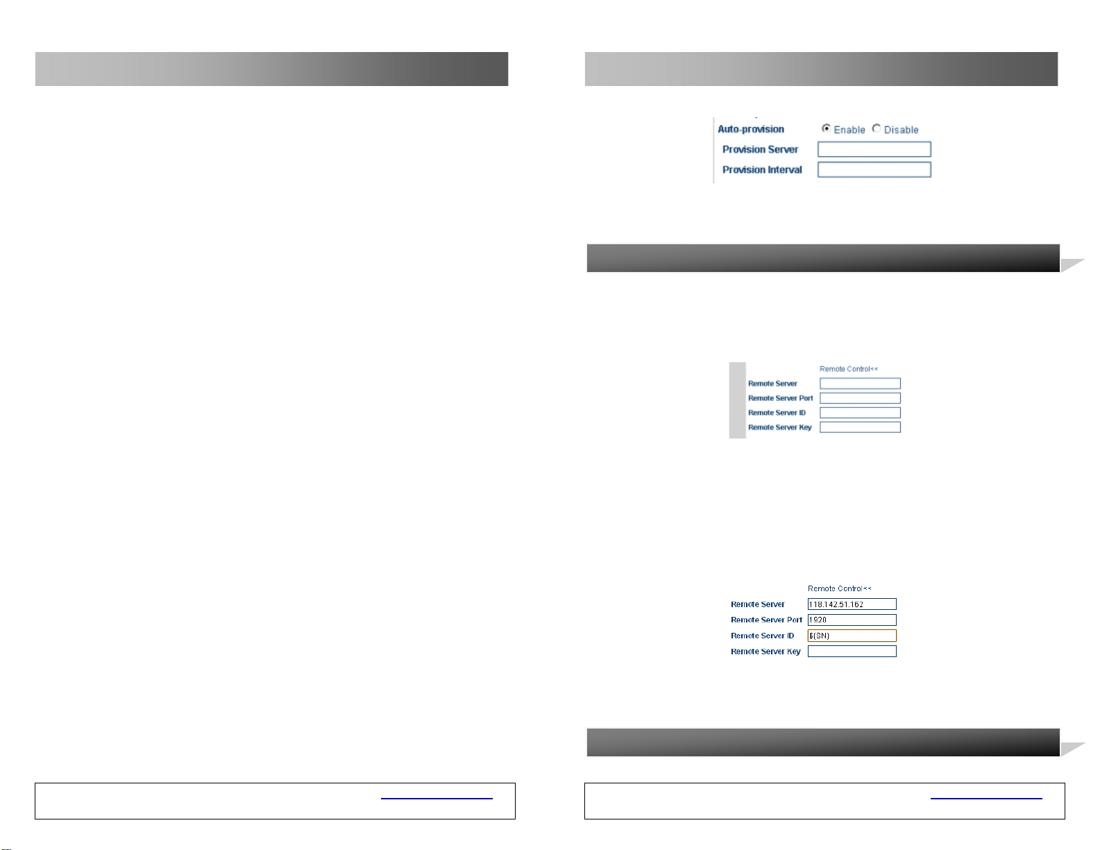
3.3.4 Automatic Setting
If the service provider provides the automatic setting, you can sele ct “Enable” to
start the automatic setting feature and enter the address of the server. If the
service provider does provide the automatic setting, you need to select “D isable”
to speed up the startup time of the GSM VOIP Gateway
GSM VOIP Gateway USER MANUAL – Rev1 – Technical Support: [email protected]
COPYRIGHT ©2011 WITURA CORPORATION SDN BHD
16
GSM VOIP Gateway sends a call request through the SIP number of the GSM VOIP
Gateway, the GSM VOIP Gateway will automatically add the number of the short
message sender to the PSTN Forwarding Number in Cal Forwarding (VoIP
Incoming Call , Forwarding to the PSTN Immediately);
In this mode, when the GSM VOIP Gateway receives the call from the SIP server,
the GSM VOIP Gateway will forward the call to the short message sending
equipment through the GSM network.
The SMS dial prefix is still valid in this mode;
The call request signaling in this mode is as follows:
SendingMessage to 192.168.2.1:5060:
INVITE
sip:8675588228822*[email protected]:5060;transport=udp
SIP/2.0
Via: SIP/2.0/UDP 192.168.2.237:5060;branch=z9hG4bK363969813
From: <sip:[email protected]:5060>;user=phone;tag=65248630
To: <sip:8675588228822*[email protected]>
Call-ID: [email protected]
CSeq: 2 INVITE
Contact: <sip:[email protected]:5060>
Max-Forwards: 30
User-Agent:H
Allow: INVITE, ACK, BYE, CANCEL, OPTIONS, NOTIFY, REFER, REGISTER,
MESSAGE, INFO, SUBSCRIBE
Content-Type: application/sdp
GSM VOIP Gateway USER MANUAL – Rev1 – Technical Support: [email protected]
COPYRIGHT ©2011 WITURA CORPORATION SDN BHD
61
Page 17
GSM VOIP Gateway Series
GSM VOIP Gateway Series
SendingMessage to 192.168.2.1:5060:
INVITE sip:[email protected]:5060;transport=udp SIP/2.0
Via: SIP/2.0/UDP 192.168.2.237:5060;branch=z9hG4bK363969813
From: <sip:[email protected]:5060>;user=phone;tag=65248630
To: <sip:[email protected]>
Call-ID: [email protected]
CSeq: 2 INVITE
Contact: <sip:[email protected]:5060>
Max-Forwards: 30
User-Agent: H
Allow: INVITE, ACK, BYE, CANCEL, OPTIONS, NOTIFY, REFER, REGISTER,
MESSAGE, INFO, SUBSCRIBE
Content-Type: application/sdp
Content-Length: 226
Mode 3:
It is a special server, which needs the support of the specific system.
3.3.5 Setting of the Remote Control
Press *20# on the terminal to initiate the request to realize the remote
management of equipment. The remote control server is provided by the service
provider. The default port is 1920 and the terminal is identified by the SN. The
remote control password is identical with that of the server and is set as default.
In the following figure, the remote control server is set as 118.142.51.162. The
terminal user presses *20# and a long tone is heard, which indicates that the
instruction has been successfully sent. The remote administrator access
http://118.142.51.162:8086 and the model and SN of the gateway are displayed.
Click the gateway SN to set the remote gateway .
When a short message of “8675588228822” is sent from the mobile phone
number (+86)13800000000 to the GSM VOIP Gateway, the GSM VOIP Gateway
wil l send the following call reques ts . W he n
is sent from the mobile phone number (+86)13800000000 to the GSM VOIP
Gateway, the GSM VOIP Gateway wil l send the following call req uests. When the
GSM VOIP Gateway USER MANUAL – Rev1 – Technical Support: [email protected]
COPYRIGHT ©2011 WITURA CORPORATION SDN BHD
a short message of “8675588228822”
60
Note: It is a special server, which needs the support of the specific syste m. For
details, please contact the technical support Witura Corporation Sdn Bhd.
3.3.6 GSM Group Mode
GSM VOIP Gateway USER MANUAL – Rev1 – Technical Support: [email protected]
COPYRIGHT ©2011 WITURA CORPORATION SDN BHD
17
Page 18
GSM VOIP Gateway Series
GSM VOIP Gateway Series
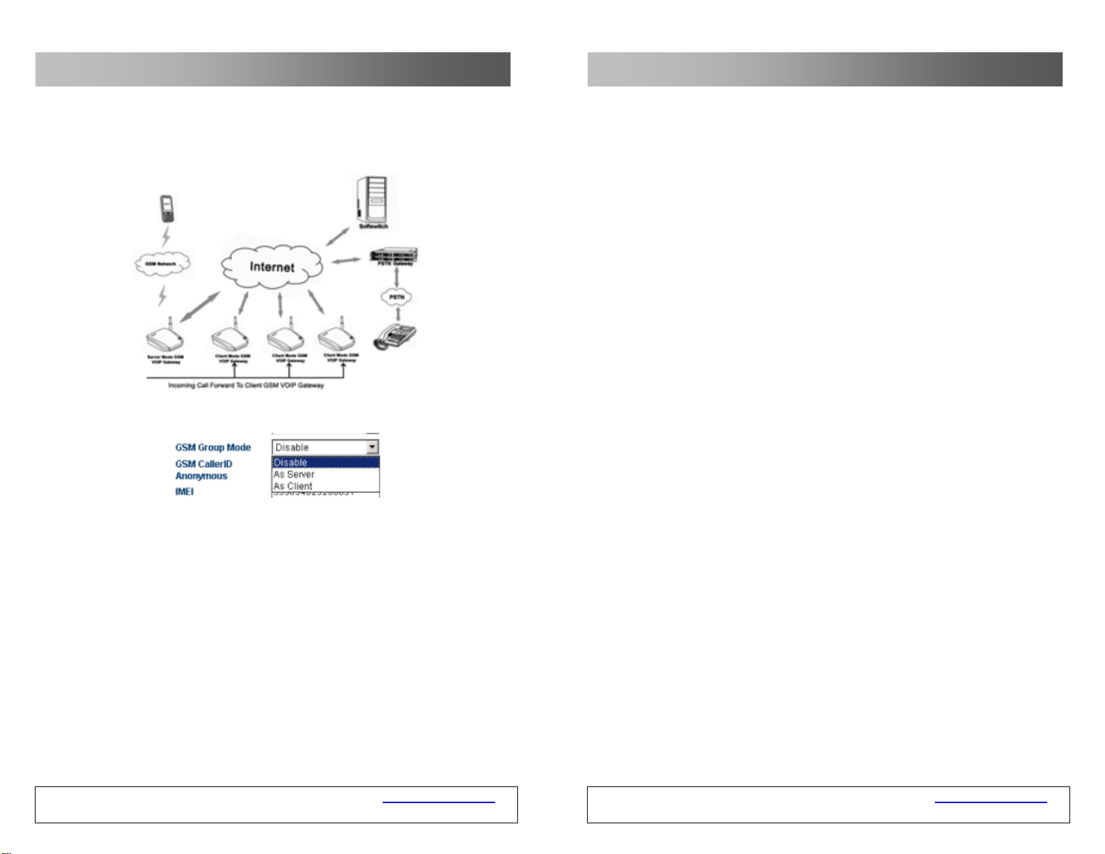
Users can establish a GSM group containing multip le GSM VOIP Gateway. Under
this mode, the administrator only needs to provide a GSM number to the user to
call in the VoIP system.
Each GSM VOIP Gateway can operate in any of the following modes:
Prohibit: This mode is used when the GSM VOIP Gateway operates independently.
Serve as the server: When GSM VOIP Gateway operates in this mode, the
administrator only needs to provide the user with a GSM number of the GSM VOIP
Gateway as a unique access number to the GSM VOIP Gateway group. In one
GSM VOIP Gateway group, only one GSM VOIP Gateway can be used as the
server. When the GSM VOIP Gateway serves as the server, the GSM un c ondit iona l
call forwarding or busy call forwarding can be activated. The unconditional call
forwarding is used to forward all incoming calls to other clients of the group. The
busy call forwarding is used to forward incoming call s to other clients of the
group when the status of the SIM card of the server is ACTIVE.
GSM VOIP Gateway USER MANUAL – Rev1 – Technical Support: [email protected]
COPYRIGHT ©2011 WITURA CORPORATION SDN BHD
18
From:
<sip:[email protected]:5060>;user=phone;tag=65248630
To: <sip:[email protected]>
Call-ID: [email protected]
CSeq: 2 INVITE
Contact: <sip: [email protected]:5060>
Max-Forwards: 30
User-Agent: H
Allow: INVITE, ACK, BYE, CANCEL, OPTIONS, NOTIFY, REFER, REGISTER,
MESSAGE, INFO, SUBSCRIBE
Content-Type: application/sdp
Content-Length: 226
Mode 2:
When a short message of “8675588228822” is sent from the mobile phone
number (+86)13800000000 to the GSM VOIP Gateway, the GSM VOIP Gateway
will send the following call requests. Whe n the GSM VOIP Gateway sends a call
request through the SIP number of the GSM VOIP Gateway, the GSM VOIP
Gateway will automatically add the numbe r of the short message sender to the
PSTN Forwarding Number in Call Forward ing (VoIP Incoming Call, Forwarding to
the PSTN Immediately);
In this mode, when the GSM VOIP Gateway receives the call from the SIP server,
the GSM VOIP Gateway will forward the call to the short message sending
equipment through the GSM network.
The SMS dial prefix is still valid in this mode;
The call request signaling in this mode is as follows:
GSM VOIP Gateway USER MANUAL – Rev1 – Technical Support: [email protected]
COPYRIGHT ©2011 WITURA CORPORATION SDN BHD
59
Page 19
GSM VOIP Gateway Series
Sending Message to 192.168.2.1:5060:
INVITE sip:8675588228822@192.168.2.1:5060;transport=udp SIP/2.0
Via: SIP/2.0/UDP 192.168.2.237:5060;branch=z9hG4bK363969813
From:
<sip:[email protected]:5060>;user=phone;tag=65248630
To: <sip:[email protected]>
Call-ID: [email protected]
CSeq: 2 INVITE
Contact: <sip: [email protected]:5060>
Max-Forwards: 30
User-Agent: H
Allow: INVITE, ACK, BYE, CANCEL, OPTIONS, NOTIFY, REFER, REGISTER,
MESSAGE, INFO, SUBSCRIBE
Content-Type: application/sdp
Content-Length: 226
When the user enters an SMS dial prefix, such as 999, the above call request
signaling is changed to:
Sending Message to 192.168.2.1:5060:
INVITE sip: [email protected]:5060;transport=udp
SIP/2.0
Via: SIP/2.0/UDP 192.168.2.237:5060;branch=z9hG4bK363969813
GSM VOIP Gateway USER MANUAL – Rev1 – Technical Support: [email protected]
COPYRIGHT ©2011 WITURA CORPORATION SDN BHD
58
GSM VOIP Gateway Series
Serve as the client: When GSM VOIP Gateway operates in this mode, it will
send it s real-time status to the server of the GSM VOIP Gateway group, so that
the GSM VOIP Gateway server can deploy the call forwarding.
Server address: It is the IP address of the GSM VOIP Gateway of the G SM VOIP
Gateway group server.
GSM number: It is the telephone number of the GSM SIM card us ed by the GSM
VOIP Gateway.
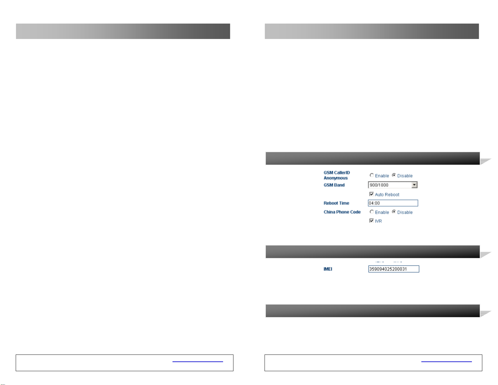
3.3.6 Anonymity Of the GSM Caller Number
The caller number can be hidden, but this needs the support of the GSM operator.
3.3.7 IMEI
The IMEI (International Mobile Equipment Identity) is an electric serial number
containing 15 digits.
3.3.8 SMS Send to Client
GSM VOIP Gateway USER MANUAL – Rev1 – Technical Support: [email protected]
COPYRIGHT ©2011 WITURA CORPORATION SDN BHD
19
Page 20
GSM VOIP Gateway Series
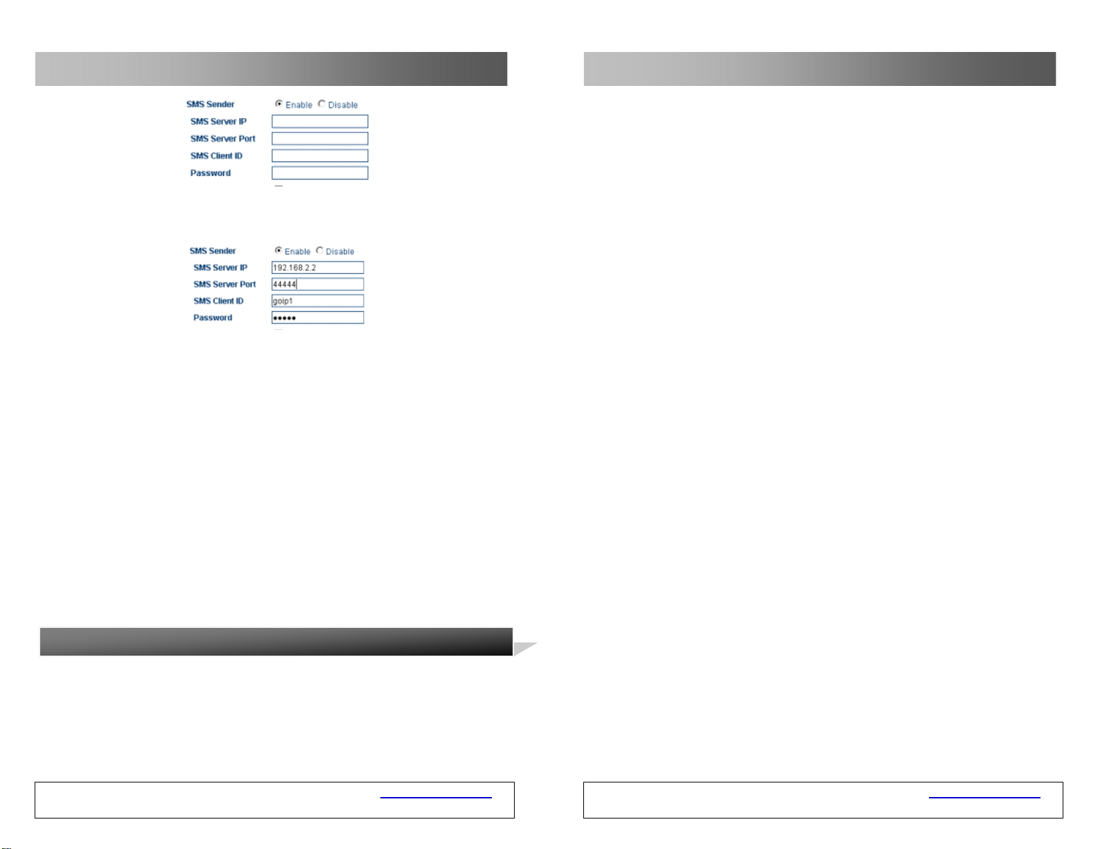
The SMS server sends the request to the mobile phone via the GSM VOIP
Gateway, or the mobile phone sends the reques t to the S MS Serv er via GSM VOI P
Gateway.
SMS server address: This is for filling the IP of the SMS server. Ple ase make
sure that server is installed with the GSM VOIP Gateway SMS management server
software independently developed by Witura Corporation Sdn Bhd (The software
can be obtained from our technical personnel).
SMS server port: It is the SMS port of the SMS server. The default value is
44444. It must be consistent with that of the server if modified on the server.
Authentication ID: It is the user ID. Make sure that the server has
corresponding ID.
Authentication password: It is for filling the user password.
Note: The SMS send cli ent of the WT-2204 and WT-2208 are in the call set
options, which needs the support of the G SM VOIP Gateway SMS management
server.
3.3.9 GSM Band
GSM VOIP Gateway Series
C: Mode 3
In this mode, the GSM VOIP Gateway sets the SIP number of the GSM VOIP
Gateway as the calling number of the call and the called number as the short
message content and the number of the short mes sage sender, whose format is
short message content*the number of the short message sender.
D: SMS Dial Prefix
When the GSM VOIP Gateway initiates the SMS call, the GSM VOIP Ga teway will
change the prefix number to the called number prefix.
Examples of SMS Dialing:
In the following SMS dialing examples, the account of the SIP of the GSM VOIP
Gateway is set as follows:
Mode 1:
The GSM VOIP Gateway support the GSM/GPRS 900/1800 and 850/1900 bands.
GSM VOIP Gateway USER MANUAL – Rev1 – Technical Support: [email protected]
COPYRIGHT ©2011 WITURA CORPORATION SDN BHD
20
When a short message of “8675588228822” is sent from the mobile phone
number (+86)13800000000 to the GSM VOIP Gateway, the GSM VOIP Gateway
will send the following call request signaling:
GSM VOIP Gateway USER MANUAL – Rev1 – Technical Support: [email protected]
COPYRIGHT ©2011 WITURA CORPORATION SDN BHD
57
Page 21
GSM VOIP Gateway Series
GSM VOIP Gateway Series
3.9 SMS Mode
The GSM VOIP Gateway permits you to call VoIP users or forward short messages
through the SMS.
3.9.1 SMS Dialing Under SIP Protocol
Under the SIP protocol, the GSM VOIP Gateway permit s users to dial back
through the SMS. After users send the called numb er to the GSM VOIP Gateway
through the SMS, the GSM VOIP Gateway will send a call request to the SIP
server automatically. Users who need this function should choose the following
parameters:
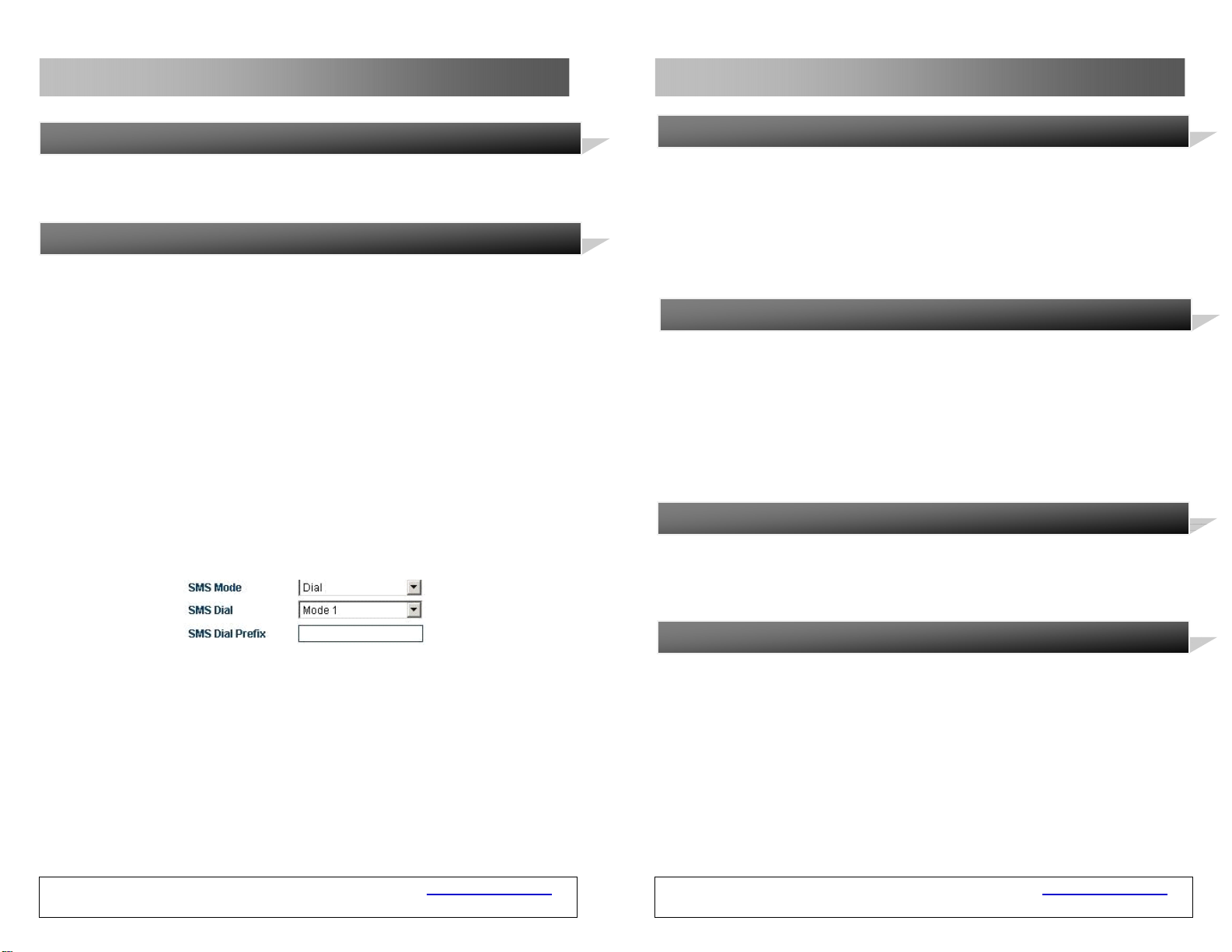
Select SMS Mode > Dial and the following page is displayed.
The GSM VOIP Gateway supports three types of outgoing call via SMS:
A: Mode 1
In this mode, the GSM VOIP Gateway sets the calling number of the SMS as the
calling number of the call and the called number as the short message content;
B: Mode 2
In this mode, the GSM VOIP Gateway sets the SIP number of the GSM VOIP
Gateway as the calling number of the call and the called number as the short
message content;
3.3.10 Timing Restart
The GSM VOIP Gateway restarts at least once at the specified time every day to
clear the buffer of the GSM VOIP Gateway, so that the GSM VOIP Gateway can
operate normally.
3.3.11 China Area Code Matching
The GSM VOIP Gateway can match all area codes of China to ensure the prompt
dial. The default status is Disable.
3.3.12 IVR
By default, the IVR is enabled. When a call comes in, the system prompts the
user to dial a second time. When the IVR is disabled, th e system will not prompt
the user to dial a second time.
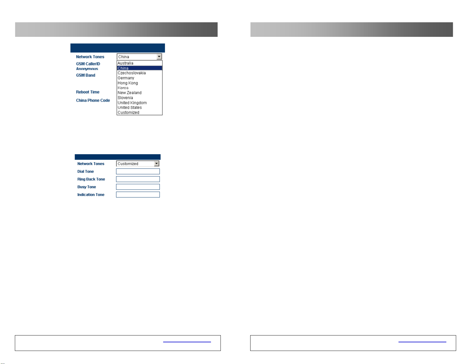
3.3.13 Prompt Tone System
The prompt tones are the combination of the intervals and frequencies of the
dialing tones and ring-back tones when users hook off the telephone. You can
select the following prompt tones for the GSM VOIP Gateway according to the
countries and regions where the GSM VOIP Gateway is used, so as to remain
conventional tones.
GSM VOIP Gateway USER MANUAL – Rev1 – Technical Support: [email protected]
COPYRIGHT ©2011 WITURA CORPORATION SDN BHD
56
GSM VOIP Gateway USER MANUAL – Rev1 – Technical Support: [email protected]
COPYRIGHT ©2011 WITURA CORPORATION SDN BHD
21
Page 22
GSM VOIP Gateway Series
Customize:
Users can customize prompt tones according to their special requirements. Select
Customize, the following setting parameters are displayed.
The setting parameters are defined as follows:
Each prompt tone involves the following parameters. If a parameter is not defined,
the value of the parameter shall be 0.
<nc, rpt, c1on, c1off, c2on, c2off, c3on, c3off, f1, f2, f3, f4, p1, p2, p3, p4>
nc: the number of tones (1-4)
rpt: the number of repeats (0 to infinity)
c1on: the duration when the frequency 1 is on (ms)
c1off: the duration when the frequency 1 is off (ms)
c2on: the duration when the frequency 2 is on (ms)
c2off: the duration when the frequency 2 is off (ms)
GSM VOIP Gateway USER MANUAL – Rev1 – Technical Support: [email protected]
COPYRIGHT ©2011 WITURA CORPORATION SDN BHD
22
GSM VOIP Gateway Series
SIM card status reporting number: The gateway can report the status of SIM
cards (remaining call duration) through the SMS. This parameter is used to
specify the mobile phone number to receive the SMS.
SIM card status reporting time: This parameter is used to specify the
remaining call duration and then send the report.
SIM card ID: This parameter is used to specify the ID of SIM cards in the short
message report. You can specify the mobile phone number corresponding to the
SIM card or any character string as the ID.
One-time call duration limit of SIM cards: This parameter is used to specify
the duration of one-time calls (by minutes).
Examples and Explanations:
SIM Card Call Duration Setting SIM Card Remaining Call Duration
The setting is same as the SIM card time limit diagram. T he total call duration of
the SIM card is 30 minutes. When the call duration is less than or equals 10
minutes, the gateway will send a short message to 13713652130 (the SIM card
ID is 2130 in the reporting message.) to report the remaining call duration. When
one-time call duration is longer than 8 minutes, the call will be disconnected.
When the call duration is over, it becomes 0. Users can dial the SIM car d number
by the mobile phone and when the second dialing tone is heard, press *10 to
restore the value.
GSM VOIP Gateway USER MANUAL – Rev1 – Technical Support: [email protected]
COPYRIGHT ©2011 WITURA CORPORATION SDN BHD
55
Page 23
GSM VOIP Gateway Series
GSM VOIP Gateway Series
This mode is used to set the above password authentication and trust list
authentication at the same time.
For a downlink call, the authentication mode is as follows: If the number in the
trust list is used to dial the user served by the PSTN, the call will be connected.
When the number you dialed is not in the trust list, you need to enter the
password after the secondary dial tone is played. Then, the call will be connected.
For an uplink call, the authentication mode is as follows: If the mobile number or
fixed number in the trust list is used to dial the user served by the VoIP, the call
will l be connected. When the nu mber you dialed is not in the trus t list, you nee d
to enter the password after Please Enter the Password i s played. Then, the call
will be connected.
3.8 Call Duration Limit
The call duration limit is to limit the ca ll duration of SIM cards in the gateway.
Through this function, you can specify t he total call duration of SIM cards. W hen
the call duration is longer than the specified value, the call s shall not be
connected to prevent the unnecessary or unsafe call charging. The setting
parameters are as follows:
The parameters are defined as follows:
SIM card limit time: This parameter sets the total call durat ion of SIM cards.
When the call duration is longer than the specified time (by minutes), the call
cannot be connected. When this parameter is null, the default call duration is
infinite.
c3on: the duration when the frequency 3 is on (ms)
C3off: the duration when the frequency 3 is off (ms)
f1: the frequency of tone #1, 300 to 3000Hz
f2: the frequency of tone #2, 300 to 3000Hz
f3: the frequency of tone #3, 300 to 3000Hz
f4: the frequency of tone #4, 300 to 3000Hz
p1: the increment of tone #1, 0 to 31(0=3dB, -1dB increments)
p2: the increment of tone #2, 0 to 31(0=3dB, -1dB increments)
p3: the increment of tone #3, 0 to 31(0=3dB, -1dB increments)
p4: the increment of tone #4, 0 to 31(0=3dB, -1dB increments)
Example:
To add a prompt tone where f1 is 450Hz, c1on is 750ms, and c1off is 1000ms,
enter the following values in the corresponding boxes:
1,0,750,1000,0,0,0,0,450,0,0,0,20,0,0,0
3.4
Click the “Network Setting” in the menu on the left, and the following page is
displayed:
Network Setting
GSM VOIP Gateway USER MANUAL – Rev1 – Technical Support: [email protected]
COPYRIGHT ©2011 WITURA CORPORATION SDN BHD
54
GSM VOIP Gateway USER MANUAL – Rev1 – Technical Support: [email protected]
COPYRIGHT ©2011 WITURA CORPORATION SDN BHD
23
Page 24
GSM VOIP Gateway Series
3.4.1 LAN Port Setting
The LAN port of the GSM VOIP Gateway can be set to the dynamic IP through
DHCP, fixed IP, and PPPoE dialing. There are three setting modes:
A. Dynamic IP (DHCP)
This setting is default. If the network for the user provide s the DHCP service, the
GSM VOIP Gateway will require the network information such as IP address from
the DHCP server automatically.
B. Fixed IP
Select fixed IP, and the following setting page is displayed.
GSM VOIP Gateway Series
Downlink Uplink
The setting is as follows: Select “Forward to PSTN Authentication Mode ” > “Trust
List Authentication”. Click the “VoIP Trust Number List”, and the VoIP Trust
Number List is displayed (Maximum 15 tr ust numbers can be entered). Enter the
trust VoIP number in trust number sequence.
If only a VoIP trust number, such as 330 6, is set, only the number 3306 can be
used to dial the PSTN from the VoIP.
3.7.2.3 Password of Trust List Authentication
GSM VOIP Gateway USER MANUAL – Rev1 – Technical Support: [email protected]
COPYRIGHT ©2011 WITURA CORPORATION SDN BHD
24
GSM VOIP Gateway USER MANUAL – Rev1 – Technical Support: [email protected]
COPYRIGHT ©2011 WITURA CORPORATION SDN BHD
53
Page 25
GSM VOIP Gateway Series
GSM VOIP Gateway Series
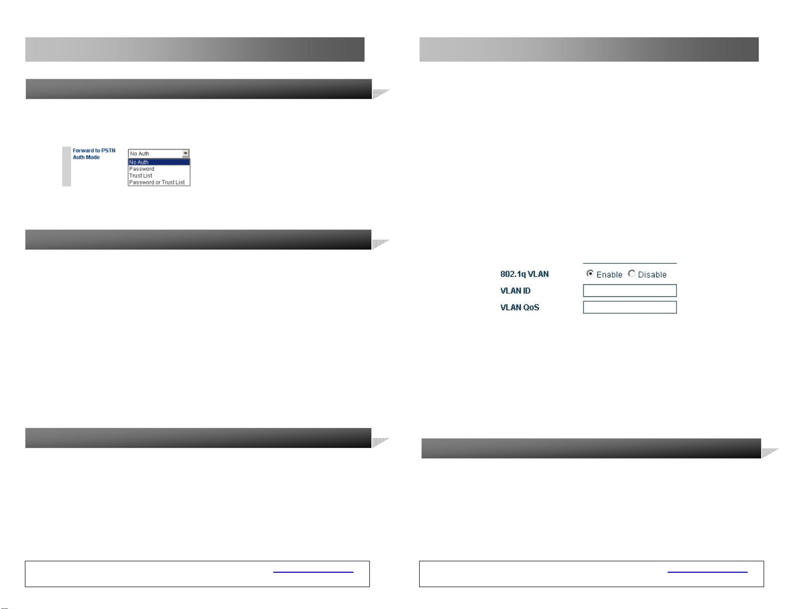
3.7.2 Authentication Mode Setting
The authentication mode is classified into the password authen tication, trust list
authentication, and password or trust list authenti cation.
Downlink (VoIP to PSTN) Uplink (PSTN to VoIP)
authentication mode authentication mode
3.7.2.1 Password Authentication
The setting is as follows: Select “Forward to PSTN Authentication Mode” >
“Password Authentication”. Enter the password in “Call PSTN Authentication
Password”.
As indicated in the above figure, for call s from the VoIP to the PSTN, when the
second dialing tone is heard, dial the set password and the call will be connected.
For call s from the PSTN to the VoIP), when “Pl ease Enter the Pa ssword” is play ed,
enter the password and then the call will be connected.
3.7.2.2 Trust List Authentication
Set these parameters according to the networ k the user uses.
C. PPPOE
PPPoE (Point-to-point protocol over Ethernet) is a network protocol that
compresses the PPP in the Ethernet. Select PPPoE dia ling, and enter the account
and password provided by the network provider.
D. 802.1qVLAN
When the network serving the user provides the VLAN service, enter the
parameter as required.
E. Advance…
Click Advance, and the Hardware address and Broadcast address are displayed in
the page.
The hardware address is used to enter the MAC address in th e format of XX: XX:
XX: XX: XX: XX.
The broadcast address is used to communicate with other computers connected
to the GSM VOIP Gateway.
3.4.2 PC Port Setting
The PC port can be set to connect other network equipment through the route or
bridging mode. The two setting modes are as follows:
A. Bridging
When the PC port is set to the bridging mode, the relation betw een the LAN port
and the PC port is layer 2 switching. The network equipment con nected with the
PC port same as the connection with the LAN port.
GSM VOIP Gateway USER MANUAL – Rev1 – Technical Support: [email protected]
COPYRIGHT ©2011 WITURA CORPORATION SDN BHD
52
GSM VOIP Gateway USER MANUAL – Rev1 – Technical Support: [email protected]
COPYRIGHT ©2011 WITURA CORPORATION SDN BHD
25
Page 26
)
GSM VOIP Gateway Series
GSM VOIP Gateway Series
B. Fixed IP Address
Select the fixed IP, and the following setting parameters are dis played. Enter the
IP address and subnet mask (the network section of the IP address should be
different from that of the LAN port to prevent conflict).
C. Enable the DHCP Service
This service can be enabled only when the PC port of the GSM VOIP Gateway is
set as the fixed IP. To enable the DHCP service, you need to enter the start
address and end address.
D. Advance…
Click Advance, and the Hardware address and Broadcast address are displayed in
the page.
The hardware address is used to enter the MAC address in th e format of XX: XX:
XX: XX: XX: XX.
The broadcast address is used to communicate with other computers that are
connected to the ATA.
3.4.3 Main DNS
The DNS (domain name system) is a database that stores the Internet na me s and
addresses, and converts between the name and the common Internet protocol
digits. The main DNS is the IP address of the main DNS (such as 202.67.156.221
or obtain from the service provider). If the PPPoE is set, the main DNS will be
automatically provided by the service provider. This parameter can be null .
3.4.4 Secondary DNS
3.7 Call Forwarding (Setting on the Call Route And
The gateway provides the call routing function for users, which can be set in the
Call Forwarding Setting. The call routing is to forward calls to specified numbers,
so that the dialing time can be decreased. In addition, the gateway provides three
authentication modes for the uplink (call s from PSTN to VoIP) and down link (call
s from VoIP to PSTN). Do not set these parameters when they are not needed.
3.7.1 Call Route Setting
Note: The value of Call PSTN must be Enabling. Otherwise, The GSM VOIP
Gateway prohibits any access to the PSTN. Therefore, set this parameter carefully.
The above Note is also suitable for Call VoIP.
1. Set a hotline number in Call PSTN Forwarded-to-number. When the user
served by the VoIP network calls the GSM VOIP Gateway, the call is forwarded
to the hotline number.
When the user served by the VoIP network call s the GSM VOIP Gatewa y, the
GSM VOIP Gateway connects the call and dials 88290211 directly. This feature
is especially useful for hotline services.
2. Set a VoIP number in Call VoIP Forwarded-to-number. When the user served
by the PSTN call s the VoIP network, the cal l is forwarded to the VoIP number.
When a user calls another user served by the PSTN, t he HT-34 2 calls t he 3306
terminal of the VoIP. When the 3306 terminal answers the call , the HT-342
connects the call and the call will be connected. This feature enables
international roamers to answer the phone through the VoIP anywhere.
Authentication Mode
Downlink: from VoIP to PSTN Uplink: from PSTN to VoIP
GSM VOIP Gateway USER MANUAL – Rev1 – Technical Support: [email protected]
COPYRIGHT ©2011 WITURA CORPORATION SDN BHD
26
GSM VOIP Gateway USER MANUAL – Rev1 – Technical Support: [email protected]
COPYRIGHT ©2011 WITURA CORPORATION SDN BHD
51
Page 27
GSM VOIP Gateway Series
GSM VOIP Gateway Series
The rule is “0:|13[0-9]xxxxxxxx:+0|[1-8]xxxxxxx:+0755”.
When you dial the number 88990011 and 8899001133, the result is the same.
The number actually dialed is 075588990011.
3.6 Volume Adjustment
The GSM VOIP Gateway has a built-in volume adjustment panel, which should be
used carefully. When you need to adjust the volume of the gateway, change the
address http://xxx.xxx.xxx.xxx/xxx/gain.html to
http://xxx.xxx.xxx.xxx/xxx/gain.html. Then, the following volume setting page is
displayed.
When the main DNS address fail s to connect o r is not avail able, the secondary
DNS can be used (such as 202.67.156.222 or obtain from the service provider). If
the PPPoE is set, the secondary DNS will be automa tically provided by the service
provider. This parameter can be null .
3.5 Call Setting
This section describes the basic setting of the network connection relating to the
GSM VOIP Gateway, which supports two protocols: H323 and SIP. The setting
page is as follows: You can select a protocol in the “Terminal Type”.
3.5.1 H.232 Terminal Setting
The H.323 protocol involves the direct connection mode and Gatekeeper mode.
3.5.1.1 Direct Connection
After the volume setting is completed, click “Save” and the setting will take effect
immediately (for ongoing calls, the setting will not take effect immediately).
Note: The adjustment on the output volume of the line ma y cause the ter minal to
fail in dialing numbers. Therefore, set this parameter car efully. The adjustment on
the input/output volume is for VoIP lines.
GSM VOIP Gateway USER MANUAL – Rev1 – Technical Support: [email protected]
COPYRIGHT ©2011 WITURA CORPORATION SDN BHD
50
Under this mode, the GSM VOIP Gateway operates in the point-to-point status.
The setting parameters are as follows:
A. H.323Telephone Number
The value of this parameter is a d ecimal numeral string that is used to confirm
the telephone number in the telephony network. For example, 5551234 is a valid
telephone number. Enter the telephone number in this parameter.
GSM VOIP Gateway USER MANUAL – Rev1 – Technical Support: [email protected]
COPYRIGHT ©2011 WITURA CORPORATION SDN BHD
27
Page 28
GSM VOIP Gateway Series
GSM VOIP Gateway Series
B. Display Name
This parameter is used to display the name of the user who subscribes the H.323
service. For example, when you call your friend John Smith, your name will be
displayed on your friend’s telephone.
C. H.323 ID
H232 ID is used to verify the account. Users can set this parameter according to
the requirements of the service provider.
D. Default Voice Gateway ay
This parameter is used to find the proper Gatekeeper or IP address of the
equipment of the call. Enter the IP address, such as 192.168.2.197, or domain
name, such as gk.yourisp.com. If the soft- switch system uses the non-standard
port (1719 and 1720), you can add the detailed port number at the end of the IP
address or domain name of the Gatekeeper. For example, if the por t number is
7300, the IP address is 192.168.2.197:7300 and the domain name is
gk.yourisp.com:7300.
Under the direct connection mode, the GSM VOIP Gateway will forward all call s to
the VoIP network to this address.
Note: The value of this parameter must be standard ASCII characters (enter
characters under the English input mode).
3.5.1.2 Gatekeeper
GSM VOIP Gateway USER MANUAL – Rev1 – Technical Support: [email protected]
COPYRIGHT ©2011 WITURA CORPORATION SDN BHD
28
3.5.7.2 Dialing Rule with Specified Length Of Numbers
If you need to specify the length of telephone nu mbers matched, you can specify
the dialing rule as “AAXXXXXX:-aa+bb”. Where, “AAXXXXXX” indicates the
number to match and the length of the number. “AA” indicates the head and
other numbers are represented by X or x. The digit s after the colon indicates
detailed actions to be taken on the number.
The setting is as follows:
In the above example 3, the rule is “00:|0:-0+00 86|:+0086755”, which can be
changed to “00:|0:-0+0086|[1-8]xxxxxxx:+0086755”.
It means that when you dial a number whose first digit is 1 to 8 and total length
is 8, the gateway will automatically dial the number and add 0086755 before the
number.
Examples:
"0:|13:+0|:+0755"
This rule enables the GSM VOIP Gateway to add 0 before the mobile phone
number and 0755 before the telephone number.
The above rule can be change to:
“0:|13[0-9]xxxxxxxx:+0|[1-8]xxxxxxx:+0755”
Similarly, this rule enables the GSM VOIP Gateway to add 0 before the mobile
phone number and 0755 before the telephone number. However, the length of
the mobile phone number is limited to 11 digits.
As shown above, the length of telephone numbers is limited to eigh t digits. 13[09]xxxxxxxx and [1-8]xxxxxxx represent mobile phone numbers 130xxxxxxxx to
139xxxxxxxx, and telephone number 1xxxxxxx to 8xxxxxxx, respectively.
Note: When the length of the number is specified, the exceeded numb ers will be
discarded if the length of the number exceeds the specified length. For example:
GSM VOIP Gateway USER MANUAL – Rev1 – Technical Support: [email protected]
COPYRIGHT ©2011 WITURA CORPORATION SDN BHD
49
Page 29
GSM VOIP Gateway Series
GSM VOIP Gateway Series
added. If the number fails to match, the number continues to match the next
rule. If no digit after the colon is specif ied, such as “00:”, it ind icates that no
actions are taken when “00” is matched and the nu mber exit s the matching.
If no digit before the colon is specified, such as “+86755”, it indicates that
instead of matching, actions are taken on the number directly.
4. You can specify a range for matching of dialing rules. The rule forma t is “[AB]A:-aa+bb” or “A[A-B]:-aa+bb”. For example, you can specify the range of
numbers beginning with 2 to 8 as “[2-8]: -aa+bb” or numbers beginning with
13 to 15 as “1[3-5]: -aa+bb”.
Examples:
1. Rule: 0:|:+0755
a. The input number is “02083185711” and the output number is “02083185711”.
b. The input number is “83185700” and the output number is “075583185700”.
2. Rule: “00:-00|0"-0+86|:+86755”
a. The input number is “008522343318” and the output number is
“8522343318”.
b. The input number is “02083185711” and the output number is
“862083185711”.
c. The input number is “83185700” and the output number is “8675583185700”.
3. Rule: “00:|0:-0+0086|:+0086755”
a. The input number is “008522343318” and the output number is
“008522343318”.
b. The input number is “02083185711” and the output number is
“00862083185711”.
c. The input number is “83185700” and the output number is
“008675583185700”.
4. Rule: “0:|1[3-9]:+0|[2-8]:+0755|:+0755”
a. The input number is “076322343318” and the output number is
“076322343318”.
b. The input number is “13044557766” and the output number is
“013044557766”. Or, the input number is “13644557766” and the output
number is “013644557766”.
c. The input number is “23185700” and the output number is “075523185700”.
Or, the input number is “73185700” and the output number is
“075573185700’.
GSM VOIP Gateway USER MANUAL – Rev1 – Technical Support: [email protected]
COPYRIGHT ©2011 WITURA CORPORATION SDN BHD
48
Under the Gatekeeper mode, the GSM VOIP Gateway operates in the H.323
register status. When you register through the H.323 protocol, select “H.323
Terminal” in “Terminal Type”, as shown in the above figure. The registration
mode involves the Gatekeeper and direct connection (the direct conne ction mode
is used for call s over the IP address). Whe n all lines use one number, s elect the
single server setting mode. When all lines use d ifferent numbers, select the line
setting mode. When you select the line setting mode, each line can be registered
to different servers. The setting parameters are as follows:
A. H.323Telephone Number
The value of this parameter is a d ecimal numeral string that is used to confirm
the telephone number in the telephony network. For example, 191 is a valid
telephone number. Enter the telephone number in this parameter.
B. Gateway ay Prefix
When you register through the gateway prefix, enter the prefix number. When
the prefix number is called, a dialing tone is heard and then the secondar y dialing
is required. The gateway prefix enables the one-stage dialing. When users dial the
gateway prefix and the telephone number, the gateway will automatically dial the
number without the prefix. For example, the current gateway prefix is 123. If a
user calls 075588290211, the user dials 123075588290211 on the IP phone.
C. Display Name
This parameter is used to display the name of the user who subscribes the H.323
service. For example, when you call your friend John Smith, your name will be
displayed on your friend’s telephone.
D. H.323 ID
H232 ID is used to verify the account. You can enter this parameter according to
the requirements of the service provider.
E. Gatekeeper Address
This parameter is used to find the proper Ga tekeeper. Ente r the IP address of t he
Gatekeeper, such as 192.168.2.197, or domain name, such as gk.yourisp.com. If
the soft-switch system uses the non-standard port (1719 and 1720), you can add
the detailed port number at the end of the IP address or domain name of the
Gatekeeper. For example, if the port number is 7300, the IP address is
192.168.2.197:7300 and the domain name is gk.youris p.com:7300.
GSM VOIP Gateway USER MANUAL – Rev1 – Technical Support: [email protected]
COPYRIGHT ©2011 WITURA CORPORATION SDN BHD
29
Page 30
GSM VOIP Gateway Series
GSM VOIP Gateway Series
Under the Gatekeeper mode, the GSM VOIP Gateway will forward all calls to the
VoIP network to this address.
Note: The value of this parameter must be standard ASCII characters.
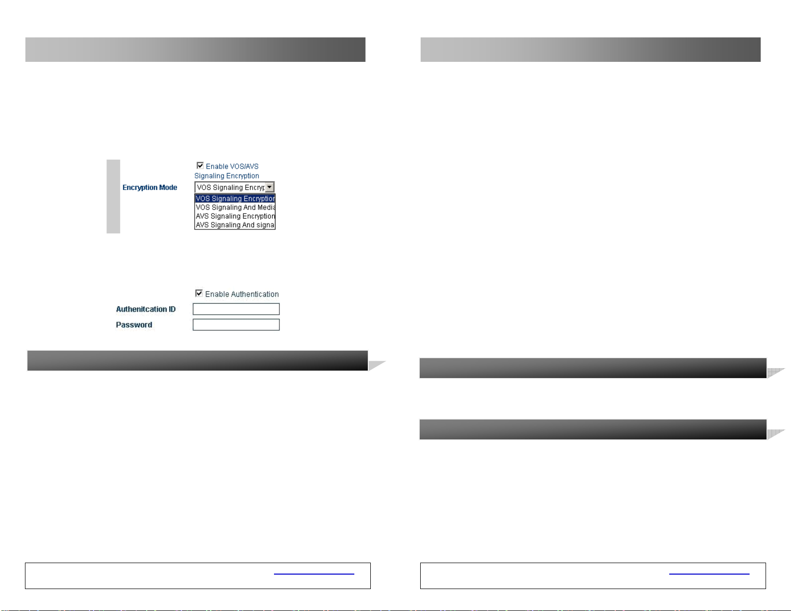
F. Enable VOS/AVS Encryption
You can enable the VOS/AVS encryption.
G. Enable Authentication on(Auth)
Click “Enable Authentication” and enter the follow ing parameters when you need
to set the H.235 authentication code and password.
3.5.1.3 Advance Setting of the H.232
The advance option of the GSM VOIP Gateway involves the signaling and media,
corresponding to “Advance Setting” and “Media” respectiv ely.
Select “Advance Setting” under H.323 and the following setting page is displayed:
GSM VOIP Gateway USER MANUAL – Rev1 – Technical Support: [email protected]
COPYRIGHT ©2011 WITURA CORPORATION SDN BHD
30
C. STUN (RFC 3489)
The Simple Traversal of UDP over NAT (STUN) is a protocol that enables the SIP
telephone to detect the existence and type of the firewall installed in the
computer. This parameter indicates the SIP address of the STUN server.
Note: The STUN protocol supports the SIP gateway only.
D. Trunk Agent
The trunk agent protocol is a firewall traversal technology developed by Witura
Corporation Sdn Bhd. It enables the products of by Witura Corporation Sdn Bhd to
be applicable for most LANs. It involves the address, port, user name and
password. The trunk agent protocol supports encryption on communications over
the gateway. This feature needs the support of the serv er developed by Witura
Corporation Sdn Bhd.
Media agent mode:
Mode 1: media encryption and agent (supported by all versions of relay
servers).
Mode 2: media encryption and agent, supporting the transit over the
specified port (supported by V2 relay server).
Mode 3: media encryption and agent for the conversion of RTP data to
TCP packet, supporting the transit over the specified port
(supported by the relay server later thanV2).
3.5.7 Dialing Rules
The GSM VOIP Gateway supports number dialing by rules. You can specify dialing
rules in the dialing rule parameter of the “Call Forwarding”.
3.5.7.1 Format Of Dialing Rules
1. You can specify multiple rules, which are separated by the delimiter ‘|’. For
example, “00:-00|0:-0+86|:+86755”.
2. The number is matched from the lef t of the dialing r ules to th e right. When the
number matches the correct rule, the numb er stops matching. Otherwise, th e
number continues to match the next rule.
3. The rule format is “AA:-aa+bb”, such as “0:-0+86”. Where, “AA” indicates the
number to match and “-aa+bb” indicates detailed actions to be taken on the
number. If the number is successfully matched, “aa” is deducted and “bb” is
GSM VOIP Gateway USER MANUAL – Rev1 – Technical Support: [email protected]
COPYRIGHT ©2011 WITURA CORPORATION SDN BHD
47
Page 31
GSM VOIP Gateway Series
C. Trunk Agent
The trunk agent protocol is a firewall traversal technology developed by
Witura Corporation Sdn Bhd. It enables the products of Witura Corporation Sdn
Bhd to be applicable for most LANs. It involves the address, port, user n ame and
password.
The trunk agent protocol supports encryption on communications over the
gateway. This feature needs the support of the server developed by Witura
Corporation Sdn Bhd.
3.5.6.3 Media NAT Traversal
The media NAT (firewall) traversal is classified into four types:
A. No firewall
The firewall traversal mechanism is not supp orted.
B. Port Transparency/DMZ
The port transparency is used to transf er the n etwork por t on th e LA N in terface t o
the computer or the server in the LAN. This feature enables external users
(through the Internet in most cases) to share the services of internal servers
(such as FTP, HTTP, and Telnet).
The port transparency supports the address of the gateway and response server.
The gateway is a communication device that connects two different networks. Th e
response server is a standard service device that implements the ECHO protocol.
GSM VOIP Gateway USER MANUAL – Rev1 – Technical Support: [email protected]
COPYRIGHT ©2011 WITURA CORPORATION SDN BHD
46
GSM VOIP Gateway Series
A. RAS Port
The RAS is the communication protocol between the term inal and th e Ga teke eper .
It is used to transmit the registration information, login, broadband change, a nd
the status between two H.323. The RAS port can be used to spe cify the UDP and
used with the router port for mapping.
B. Call Signaling Port (Q.931 Port)
H.225-Q.931 is a call control protocol of the H.323 for transmits ting the call
setting and unloading information between two H.323 units. It is used to specify
the Q.931 port (TCP) that receives call s and used with the router port for
mapping.
C. Media Control ol Port (H.245 Port)
H.245 is the media control protocol of the H.323. It is used to specify the port
that receives the H.245 connection (TCP) and used with the router port for
mapping.
D. Fast Start
You can enable or disable the fast start described in the H255.0 protocol. This
parameter is used to detect and solve the compatibility problem. If you are not
sure, do not set this parameter.
E. Fast Start Extension
This parameter is set for the special requirement of some customers. If you are
not sure, do not set this parameter.
GSM VOIP Gateway USER MANUAL – Rev1 – Technical Support: [email protected]
COPYRIGHT ©2011 WITURA CORPORATION SDN BHD
31
Page 32
GSM VOIP Gateway Series
F. H245 Tunnel
This parameter is set for the special requirements of some customers. If you are
not sure, do not set this parameter.
G. Registration Mode
This parameter is used to comply with different PBXs and is not set normally.
GSM VOIP Gateway Series
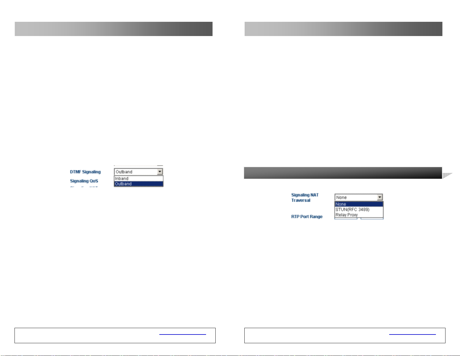
H. DTMF Signals
DTMF signals are used to transmit call signal s to the call swit ching cen ter over the
audio band. The DTMF means that two different frequencies of sounds are
combined to 16 types of dialing tones. The telecom office or 1860 service hotline
identify these dialing tones by analyzing the DSP, and thus determining the
dialing number. There are two types of DTMFs: in-band DT MF and ou t-band DTM F.
1) In-band DTMF
The in-band DTMF transmit s dialing tones and call voices togeth er, without any
processing. Therefore, the in-band DTMF transmits DTMF signals through a s ingle
way.
2) Out-band DTMF
The out-band DTMF transmits dialing tones over protocols, such as RFC2833,
which can ensure the validity of the transmi ssion.
I. Signaling QoS
Quality of Service (QoS) is a network’s capacity to provide priority services,
including the special bandwidth, jitter co ntrol and delay (used for real-time and
interactive traffic), and impro vement of the packet loss ratio. This parameter i s
used to mark the specified QoS label for the cal l signaling packet to increase the
network service quality.
GSM VOIP Gateway USER MANUAL – Rev1 – Technical Support: [email protected]
COPYRIGHT ©2011 WITURA CORPORATION SDN BHD
32
The trunk agent protocol supports encryption on communications over the
gateway. The H323 trunk agent protocol supports encryption on signaling in
different modes (for detail s about the agent mode, see sect ion 3.5.6.3 “Media
NAT Traversal”).
Note: This feature needs the support of the server developed by Witura
Corporation Sdn Bhd
3.5.6.2 Traversal Of SIP Signaling Over NAT
The traversal of SIP signaling over NAT (firewall) is classified into:
A. No
The mechanism of firewall traversal is not supported.
B. STUN (RFC 3489)
The Simple Traversal of UDP over NAT (STUN) is a protocol that enables the SIP
phone to detect the existence and type of the firewall installed in the computer.
This parameter indicates the SIP address of the STUN server.
GSM VOIP Gateway USER MANUAL – Rev1 – Technical Support: [email protected]
COPYRIGHT ©2011 WITURA CORPORATION SDN BHD
45
Page 33
GSM VOIP Gateway Series
In the advance option of the call setting, the signaling and media have separate
firewall setting, as shown in the following figures.
3.5.6.1 Traversal of H323 Signaling Over NAT
The traversal of H323 signaling over NAT (firewall) is classified into 4 categories:
A. No
The mechanism of firewall traversal is not supported.
B. Nat Citron
The Citron is a special firewall traversal protocol for GnuGK and used with GnuGK.
C. Port Transparency/DMZ
The port transparency is used to transf er the n etwork por t on th e LA N in terface t o
the computer or the server in the LAN. This feature enables external users
(through the Internet in most cases) to share the services of internal servers
(such as FTP, HTTP, and Telnet).
The port transparency supports the address of the gateway and response server.
The gateway is a communication device that connects two different networks. Th e
response server is a standard service device that implements the ECHO protocol.
D. Trunk Agent
The trunk agent protocol is a firewall traversal technology develop ed by Witura
Corporation Sdn Bhd. It enables the products of Witura Corporation Sdn Bhd to be
applicable for most LANs. It invo lves the address of the trunk proxy ser ver, port,
user name and password.
GSM VOIP Gateway USER MANUAL – Rev1 – Technical Support: [email protected]
COPYRIGHT ©2011 WITURA CORPORATION SDN BHD
44
GSM VOIP Gateway Series
3.5.2 SIP Phone
The SIP (Session Initiation Protocol) is a simple network protocol that has less
hierarchy and facilitates the initiation of calls among users. The call s may be
conducted between two or more users, which include the sounds, ima ges, sessio n,
interactive games, and virtual reality.
3.5.2.1 Setting Mode
The VoIP channel of the GSM VOIP Gateway can be set in the following three
modes: single server, line setting, and trunk gateway.
Figure 3-31 Setting Mode in the SIP Terminal
A) Single server mode: Multiple VoIP channels can share the same setting.
B) Line setting: Each VoIP channel can be served by different service providers
or served by the same service provider. In the latter case, multiple differen t
telephone numbers (accounts) can be registered on t he same service, so that
each telephone number is bound to the corresponding VoIP channel.
C) Trunk Gateway: This mode is used to establish the connection or channel
between the soft-switch and the ga teway to realize the transit between two
ends.
GSM VOIP Gateway USER MANUAL – Rev1 – Technical Support: [email protected]
COPYRIGHT ©2011 WITURA CORPORATION SDN BHD
33
Page 34
GSM VOIP Gateway Series
GSM VOIP Gateway Series
3.5.2.2 Single Server Mode
The setting parameters relating to the SIP ar e as fo llows:
A) Telephone Number
This parameter is used to set the telephone number of the lin e. The telephone
number is a unique ID when the gateway serves as the caller.
B) SIP Proxy Server
This parameter is used to set the address of the SIP proxy server. If the SIP
proxy server uses the special port (other than the SIP default port: 5 060), you
can add the detailed port number at the end of the IP address or domain name of
the proxy server. For example, 192.168.2.26:3000 or hy.con.com:3000.
C) SIP Registration Server
The SIP registration server is a server used by the gateway to register the
account. This parameter is used to se t the IP address or domai n name of the SI P
login server. If the SIP registration server uses a special port (other than the SIP
default port: 5060), you can add the detailed port number at the end of the IP
address or domain name of the registration server. For example,
192.168.2.26:3000 or hy.con.com:3000.
D) Outbound Proxy
The outbound proxy is mainly used in the scenarios where the firewall or NAT
exists, so that the signaling and media stream can penetrate the firewall .
C. Jitter Delay Processing Mode
This parameter is used to specify the algorithm model of the jitter delay buffer.
The “Adaptive” mode should be set. Other modes are only used for tests and
should not be set in actual applications.
D. Media QoS
Quality of Service (QoS) is a network’s capacity to provide priority services,
including the special bandwidth, jitter co ntrol and delay (used for real-time and
interactive traffic), and impro vement of the packet loss ratio. This parameter i s
used to mark the specified QoS label for the v oice packet to incr ease the network
service quality.
Note: For details about media encryption and media NAT penetration, refer to
3.5.5 Voice Coding And Sequence
This parameter is used to modify the compression coding according to the
requirements of the service provider.
If a compression coding is ticked, it indicates that the compression coding is
available. The UP and DOWN are used to adjust the priority of the se lected voice
compression coding.
3.5.6 Firewall Penetration
GSM VOIP Gateway USER MANUAL – Rev1 – Technical Support: [email protected]
COPYRIGHT ©2011 WITURA CORPORATION SDN BHD
34
GSM VOIP Gateway USER MANUAL – Rev1 – Technical Support: [email protected]
COPYRIGHT ©2011 WITURA CORPORATION SDN BHD
43
Page 35
GSM VOIP Gateway Series
GSM VOIP Gateway Series
2) Out-band DTMF
The out-band DTMF transmit s dialing tones over protocols, such as RFC2833 and
SIP INFO, which can ensure the validity of the transmission.
F. Registration Mode
When the registration information is sent to the platform under Mode 1,
“experise” info is included. When the registration information is sent to the
platform under Mode 2, “experise” variable is not sent.
3.5.4 Media Advance Setting
The media advance setting is set for the RTP media stream of the gateway. Select
“Call Setting” > “Media” and the following setting parameters are displayed:
A. RTP Port (Range)
This parameter is used to specify the UDP of the RTP and used wi th the router
port for mapping. Note: The terminal will use multiple pairs of RTPs (depending
on the number of lines that the terminal supports). The value o f this parameter
ranges from 5500 to 5520.
B. Packet Length (ms)
This parameter indicates the duration of sending a network packet. If this
parameter is null, it indicates that the default value is 20ms. It is used to specify
the size of the media packet. The unit is ms (the actual number of bytes depends
on the compression algorithm).
E) Homing Domain
This parameter is used for the domain management host of the SIP (a host that
provides the SIP service).
F) Authentication on ID
This parameter is used to set the authentica tion account when the gateway logs
into the SIP proxy server.
G) Password
This parameter is used to set the authentication password when the gateway log s
into the SIP proxy server.
H) Display Name
When you call your friend John Smith, your name will be displayed on your
friend’s telephone.
I) Backup Server
This parameter is used for registration backup. When a backup registration server
exists in the user’s system, the user can enable this parameter. Once the backup
server is enabled, the gateway will automatically log into the backup server in
case of the failure of the main server.
GSM VOIP Gateway USER MANUAL – Rev1 – Technical Support: [email protected]
COPYRIGHT ©2011 WITURA CORPORATION SDN BHD
42
GSM VOIP Gateway USER MANUAL – Rev1 – Technical Support: [email protected]
COPYRIGHT ©2011 WITURA CORPORATION SDN BHD
35
Page 36
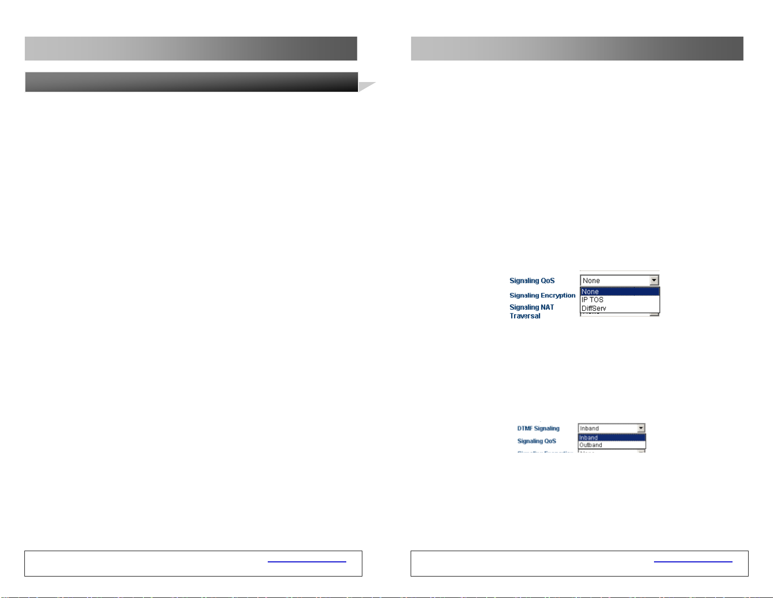
GSM VOIP Gateway Series
GSM VOIP Gateway Series
3.5.2.3 Setting by Line (Valid for the WT-2204 and WT-2208)
WT-2204 config by line
C. Timeout Setting
D. Signaling QoS
Quality of Service (QoS) is a network’s capacity to provide priority services,
including the special bandwidth, jitter co ntrol and delay (used for real-time and
interactive traffic), and impro vement of the packet loss ratio. This parameter i s
used to mark the specified QoS label for the cal l signaling packet to increase the
network service quality.
E. DTMF Signals
DTMF signals are used to transmit call signal s to the call swit ching cen ter over the
audio band. The DTMF means that two different frequencies of sounds are
combined into 16 types of dialing tones. The telecom office or 1860 service
hotline identifies these dialing tones through analyzing the DSP, and thus
determines the dialing number. There are two types of DTMF signals: in-band
DTMF and out-band DTMF.
WT-2208 config by line
You need to set parameters for each line and the setting method is the same. The
setting parameters are as follows:
A) Telephone Number
This parameter is used to set the telephone number of the lin e. The telephone
number is an unique ID when the gateway serves as the caller.
GSM VOIP Gateway USER MANUAL – Rev1 – Technical Support: [email protected]
COPYRIGHT ©2011 WITURA CORPORATION SDN BHD
36
1) In-band DTMF
The in-band DTMF transmit s dialing tones and call voices togeth er, without any
processing. Therefore, the in-band DTMF transmits DTMF signals through a s ingle
way.
GSM VOIP Gateway USER MANUAL – Rev1 – Technical Support: [email protected]
COPYRIGHT ©2011 WITURA CORPORATION SDN BHD
41
Page 37
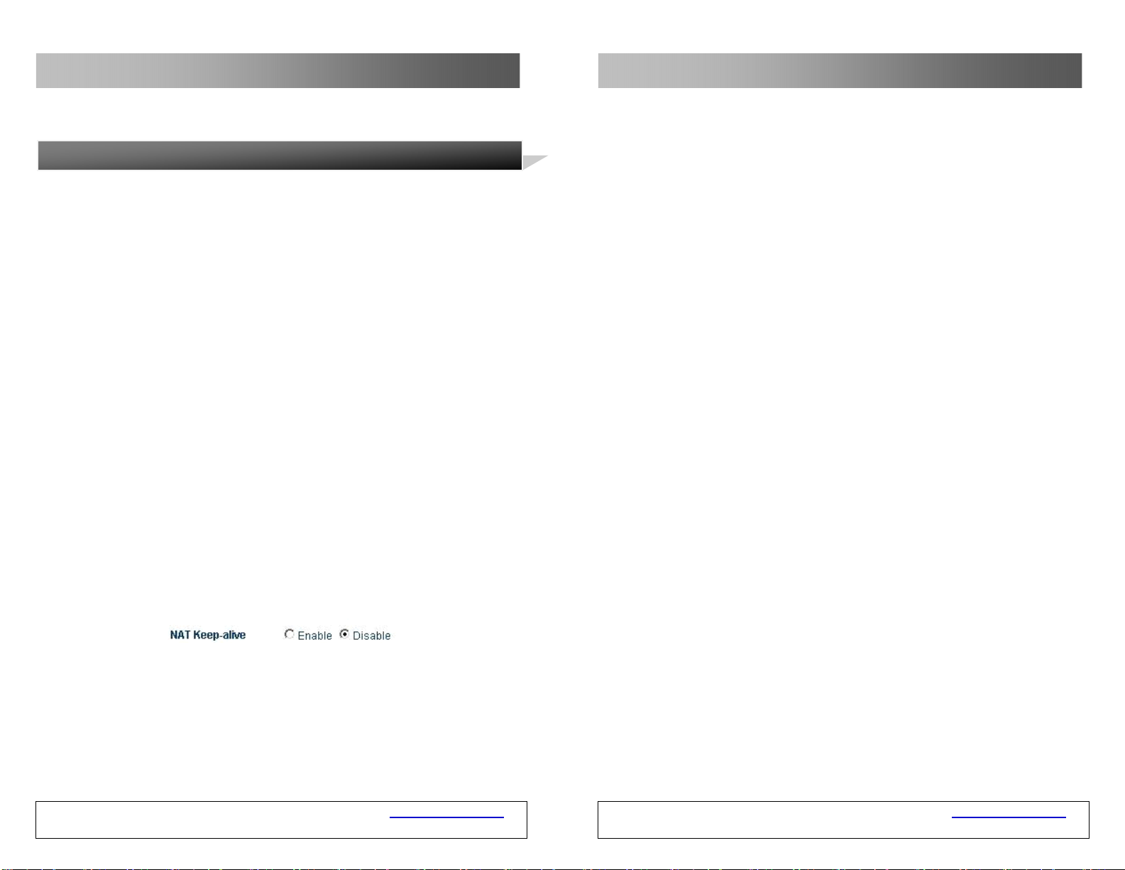
GSM VOIP Gateway Series
GSM VOIP Gateway Series
3.5.3 SIP Advance Setting
The advance setting of the SIP involves the signaling and media. User s can set
according to their special requirements.
Select SIP Menu > Advance Setting/Media.
A. Signaling Port (SIP Local Port)
The SIP local port is the local U DP port. It is used for communications betw een
the SIP agent and the SIP proxy server as well as other SIP managers.
B. NAT Hold
This parameter is used to hold the port that is activated by the NAT for SIP
signaling communication. The unit of the parameter is m.
GSM VOIP Gateway USER MANUAL – Rev1 – Technical Support: [email protected]
COPYRIGHT ©2011 WITURA CORPORATION SDN BHD
40
B) Gateway Prefix
The gateway prefix enables the connection of call s throu gh a particular line. It
can match the first digit only. You can set a gateway prefix for multiple lines.
When you set a gateway prefix for mult iple lines, the call s that have the same
gateway prefix will select the line set with this ga teway prefix. For example, the
gateway prefix is 1. When the user dials 10086, the call will be connected by the
line with the gateway prefix 1. When the user dials 075588290211, the system
detects whether the line with gateway prefix 0 exists . If exists, the call will be
connected. Otherwise, the call will be released.
Note: When you set the GSM VOIP Gateway by lines, the gateway prefix must be
set. Otherwise, the call will not be connected .
C) SIP Proxy Server
This parameter is used to set the address of the SIP proxy server. If the SIP
proxy server uses the special port (other than the SIP default port 5060), yo u can
add the detailed port number at the end of the IP address or domain name of the
proxy server. For example, 192.168.2.26:3000 or hy.con.com:3000.
D) SIP Registration Server
The SIP login server is a server that the gateway registers the account. This
parameter is used to set the IP address or domain name of the SIP registration
server. If the SIP registration server uses the special port (other than the SIP
default port 5060), you can add the detailed port number at the end of the IP
address or domain name of the registration server. For example,
192.168.2.26:3000 or hy.con.com:3000.
E) Outbound Proxy
The outbound proxy is mainly used in the scenarios where the firewall or NAT
exists, so that the signaling and media stream can penetrate the firewall.
F) Homing Domain
This parameter is used for the domain management host of the SIP (a host that
provides the SIP service).
G) Authentication ID
This parameter is used to set the authentica tion account when the gateway logs
into the SIP proxy server.
GSM VOIP Gateway USER MANUAL – Rev1 – Technical Support: [email protected]
COPYRIGHT ©2011 WITURA CORPORATION SDN BHD
37
Page 38
GSM VOIP Gateway Series
GSM VOIP Gateway Series
H) Password
This parameter is used to set the authentication password when the gateway log s
into the SIP proxy server.
I) Display Name
When you call your friend John Smith, your name will be displayed on your
friend’s telephone.
J) Backup Server
This parameter is used for registration backup. When a backup registration server
exists in the user’s system, the user ca n enable this para meter. Whe n the ba ckup
server is enabled, the gateway will automatically log into the backup server in
case of the failure of the main server.
3.5.2.4 Trunk Gateway Mode
The trunk gateway is used to connect the VoIP network with the GSM network
and convert the related protocols, so that users served by the two networks can
call each other.
GSM VOIP Gateway USER MANUAL – Rev1 – Technical Support: [email protected]
COPYRIGHT ©2011 WITURA CORPORATION SDN BHD
38
A) SIP Trunk Gateway1
It is the IP address of the server connected to the GS M VOIP Gateway. When the
registration timeout is 0, the GSM VOIP Gateway is connect ed to the SIP server.
If the registration timeout is not 0, the GSM VOIP Gateway logs into the SIP
Trunk Gateway1 server through setting the telephone number, authentication ID
and password.
B) SIP Trunk Gateway2
It is the IP address of the terminal con nected to the GSM VOIP Gateway, which
can be an IP segment, such as 192.168.2.X. This means that all terminals
connected over 192.168.2 segment can log into the GSM VOIP Gateway and land
through the direct connection between the GSM VOIP Gateway and the GSM
network.
C) SIP Trunk Gateway3
It is the IP address of the server connected to the GSM VOIP Gat eway.
D) Telephone Number
This parameter is used to set the telephone number of the lin e. The telephone
number is an unique ID when the gateway serves as the callee an d takes effect
when the GSM VOIP Gateway logs into the SIP Trunk Gateway1.
E) Registration Timeout (s)
When the registration timeout is 0, you cannot register the gateway and the
gateway will be connected to the server directly. You can reference the setting
parameters of the single server mode to register the gateway.
F) Authentication ID
This parameter is used to set the authentica tion account when the gateway logs
into the SIP Trunk Gateway1 proxy server. The parameter can b e null in the case
of interconnection.
G) Password
This parameter is used to set the authentication password when the gateway log s
into the SIP Trunk Gateway1 proxy server. The parameter can b e null in the case
of interconnection.
GSM VOIP Gateway USER MANUAL – Rev1 – Technical Support: [email protected]
COPYRIGHT ©2011 WITURA CORPORATION SDN BHD
39
 Loading...