

Page 1

Installation instructions
Remote 3000 / 3010
Content
1 General instructions __________________________________________________________ 2
1.1 Liability notes _________________________________________________________________ 2
2 Lock installation ______________________________________________________________ 2
2.1 Installing the lock ______________________________________________________________ 3
2.2 Connection external control/lock _________________________________________________ 3
3 Schematic _____________________________________________________________________ 4
4 Terms and definitions _________________________________________________________ 4
5 Technical data ________________________________________________________________ 5
6 Functional test ________________________________________________________________ 5
© Carl Wittkopp GmbH - Errors and omissions excepted
Rel. 1.0 07.10.2013 Installation instructions no. 9999-137-0
Page 2

Installation instructions Remote 3000 / 3010
1 General instructions
• Please read the operating instructions carefully, before activating the lock.
1.1 Liability notes
• The mounting of the electronic lock has to be carried out according to the installation instruction.
• By opening the lock case and by exceeding the thresholds, the manufacturer’s warranty will be void.
• The electronic lock has to be protected against external attacks.
• Do not insert any lubricants or other substances into the electronic lock.
• Only controlled mains adapters may be used for power supply.
• Durable operation with increased bolt load shortens the operating life of the lock’s mechanics.
2 Lock installation
The electronic lock has got standard fixing points and can be mounted in all 4 directions (right-hand, left-hand, up, down). In
order to fix the electronic lock, 4 threaded holes M6 have to be drilled according to the figure below.
Fig. 1: Installation dimensions Remote 7219
Hub/Stroke 12
Fig. 2: Installation dimensions Remote 7219 with optional mech. opening
2
Page 3

Installation instructions Remote 3000 / 3010
2.1 Installing the lock
• The electronic lock has to be fixed with 4 x M6 screws in the prepared drillings in order to ensure a permanent hold.
• An independent loosening of the screws has to be avoided. It is recommended to put lock washers underneath the screw’s
head. To avoid malfunctions, turn the screws with a maximum turning force of 3.5 – 5 Nm.
• After the installation the lock’s bolt may not be loaded. The maximum bolt load is 2.5 N.
• The electronic lock is maintenance free in normal domestic and office surroundings. After approx. 10,000 closures it is
recommended to carry out a security and functional test of the electronic lock.
2.2 Connection external control/lock
• Plug single conductors cable into the connecting terminal plate on the lock from/to the external control and check fixing
(see fig. 2).
• Ensure enough traction relief to the signal lead.
• To loosen single conductors push in the corresponding clutch fork (orange) with an appropriate tool.
• Keep cable away from sharp edges and moving boltwork components and fix it permanently.
Connecting terminal
Fig. 3: Connecting terminal plate electronic lock
min. 10 mm
Fig. 4: Stripping length
3
Page 4
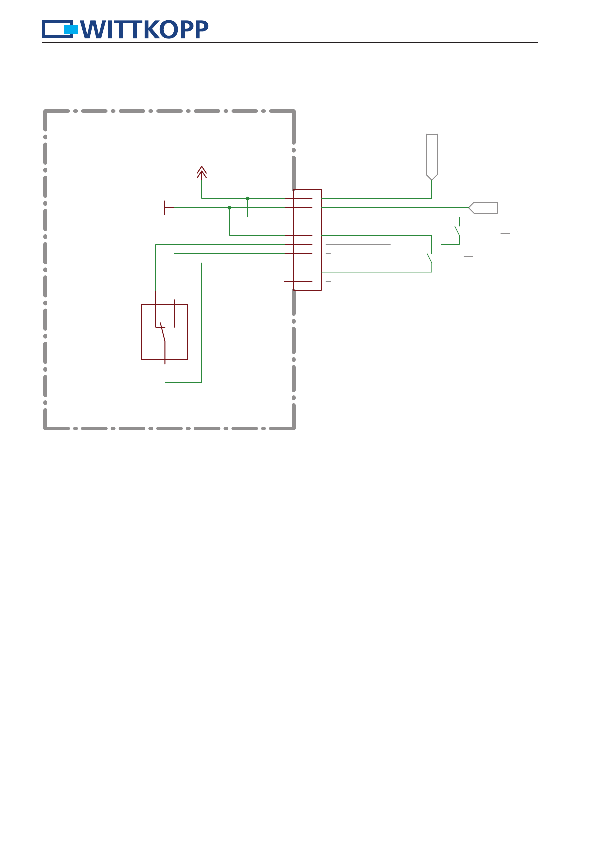
3 Schematic
NC
GND
NO
+12V
Installation instructions Remote 3000 / 3010
9-12VDC
X101
Vcc
1
power supply
2
3
4
5
6
7
secure / not secure
8
9
n.c.
10
RIACON-AST072-10
GND
open/close
blocking
not secure
S1
DH2CC6PA
COM
Abb. 4: Schematic
4 Terms and definitions
Pulse mode:
A closed lock can be opened by a single impulse and closed again by a succeeding one.
Hold mode:
If the opening signal is not turned off before the bolt reaches the opening position, the lock stays opened until the signal is
removed again. When the signal is then removed, the lock closes automatically.
Opening and closing is carried out by a signal input. The lock can be operated in pulse or hold-mode via this signal input.
4
Page 5

Installation instructions Remote 3000 / 3010
5 Technical data
Technical data
Dimensions lock (mm)
Material
Ingress protection
Temperature (°C)
Rel. humidity (%)
Operation conditions
Power supply
Voltage
Current consumption (standby *1)
Current consumption control inputs
- Open/close (mA)
- Blocking (mA)
Voltage levels control inputs
- Open/close
- Blocking
(always with reference to ground)
Output
- „Secured“
Terminal block wire gauge
(standby *1) supply voltage 12VDC, only power supply without any
(load *2) 7.5 N bold force, supply voltage 12VDC
(bold blocked *3) supply voltage 12VDC
(Vcc) 9-12 VDC +/- 10%
(load *2)
(max. *3)
BxHxT, see fig. 1 page 2
zinc plated steel sheet
IP30
5-40
10-75 % not condensating
control contacts
typ. 1 µA
< 300 mA
< 700 mA
< 0.5 mA
< 0.1 mA
5V – 12 V (max. Vcc)
0-5 V
5-500mA@30V
(data sheet Cherry DH)
0.13 – 0.5 mm² respectively AWG 26-20
• The blocking input allows to inhibit lock openings. Closing or accordingly extending the bolt, is still possible.
• The lock electronically checks at the beginning of every opening cycle, whether a blocking signal is active. To combine multiple locks like a double door system, only one common signal line is necessary (easier cabling).
• The condition „secure“, when the bolt is in closed position and retained, is signalized by switching contacts directly connected
to the terminal block (dry-contact).
6 Functional test (when the door is open)
• Carry out a functional test after installing the lock.
• Trigger the control signal.
• The lock bolt moves in automatically (has to happen easily). The lock is opened.
• After triggering another control signal (pulse mode) or after switching off the control signal (hold mode) the lock bolt moves
out automatically and locks. The lock is closed.
• Keep enough clearance to the locking point.
5
 Loading...