

Wittkopp Primor FE, Primor RO, Primor FS, Primor 100, Primor 2000 Installation Instructions Manual
...
Installation instructions Primor
Content
1 General instructions _____________________________________________________________ 2
2 System overview
3 Installation input unit Primor RE ____________________________________________________ 3
4 Installation input unit Primor FE ____________________________________________________ 5
5 Installation input unit Primor RO ___________________________________________________ 7
6 Installation input unit Primor FL ___________________________________________________ 11
_________________________________________________________________ 2
7 Installation input unit Primor FS ___________________________________________________ 13
8 Installation lock
9 Mounting lock Primor 100 _______________________________________________________ 15
10 Mounting lock Primor 1000 _____________________________________________________ 18
11 Mounting lock Primor 1000/2000/3000/3010/3011 ______________________________ 18
12 Plug positions
13 External power supply
14 Functional test
15 Testing the system
________________________________________________________________ 14
_________________________________________________________________ 21
__________________________________________________________ 21
________________________________________________________________ 22
_____________________________________________________________ 22
© Carl Wittkopp GmbH - Errors and omissions excepted
Rel. 1.6 06.02.2017 Installation instructions no 9999-154-0
Installation instructions Primor
1 General instructions
• Please read the installation instructions carefully, before activating the lock.
1.1 Liability notes
• The mounting of the electronic lock and the input unit has to be carried out according to the installation instruction.
• We point out that this installation instruction is part of the VdS-certification and non-compliance leads to the loss of this
certification.
• By opening the lock cover warranty of the manufacturer will be void.
• Take care that the input unit or the lock and the cables should not be damaged.
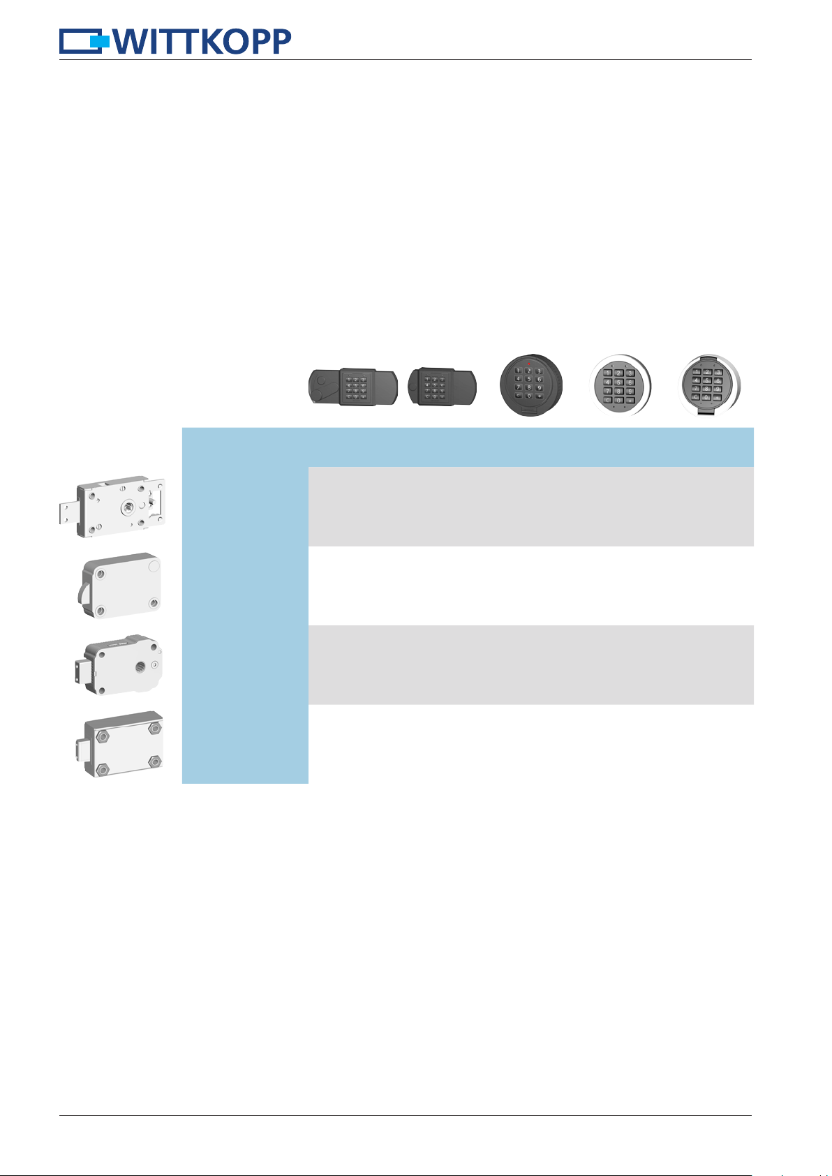
2 System overview
Primor RE Primor FE Primor RO Primor FL Primor FS
Primor 100
Primor 1000
Primor 2000
Primor
3000/3010/3011
* can serve simultaneously as boltwork actuator
• •
• •* • •
• •
• •* • •
2

Installation instructions Primor
205
30
A
A
Türlochbohrung
mind . ø10,6 - max. ø11,4
3 Installation input unit Primor RE
3.1 Input unit Primor RE 3.1.1 Dimensions Primor RE
3.2 Installation overview
3.2.1 Input unit Primor RE
83
O-ring
Axe profile
Cylinder screws
M5 x 18
Lever input unit
Black covering cap
Red covering cap
3.3 Axis length calculation input unit Primor RE
3.3.1 In connection with Primor 100 3.3.2 Panel hole spindle
Battery compartment
cover
Cylinder screws
M5 x 14
L
Spindle:
Debur the ends
L = A + 35 mm (tolerance -2 mm)
min. Ø 10.6 mm/max. Ø 11.4 mm
A
3

Installation instructions Primor
60 145
30
3.4 Mounting input unit
3.4.1 Drill pattern Primor RE (lock is closing towards the right) - (closing towards the left inversely)
Opening for cable
2 x Fixing position for
Ø 11,4
screws M5 x 14
15
2 x Fixing position
for screws M5 x 18
30
100
15
30
130
• From the front 4 threaded holes M5 with sufficient depth thread and 1 through-hole (opening for cable/Spindle)
have to be drilled into the safe door.
3.4.2 Cable guidance Primor RE 3.4.3 Cable guidance/Plug position Primor RE
Lock
O-ring
Spindle
• Lead the connection cable through the Spindle.
• Push the cable and the O-ring in the direction of the arrow until the inset.
• Connect the plug of the cable with the plug on the circuit board. Attention: Don’t put the connection cable under tensile stress.
• Fix the input unit from the front with the enclosed cylinder screws M5.
• Install covering caps and battery compartment cover (see 3.2.1).
4

Installation instructions Primor
156
4 Installation input unit Primor FE
4.1 Input unit Primor FE 4.1.1 Dimensions Primor FE
4.2 Installation overview
4.2.1 Input unit Primor FE
11,5
52,5
26
83
Cylinder screw
M5 x 18
Battery compartment cover
Black covering cap
Axe profile M5 x 14
5

Installation instructions Primor
11,5 100
4.3 Mounting input unit
4.3.1 Drill pattern Primor FE (lock is closing towards the right) - (closing towards the left inversely)
30
• From the front 3 threaded holes M5 with sufficient thread depth and 1 through-hole (opening for cable/Spindle)
have to be drilled into the safe door.
4.3.2 Plug position Primor FE
Lock
• Connect the plug of the cable with the plug on the circuit board. Attention: Don’t put the connection cable under tensile stress.
• Fix the input unit from the front with the enclosed cylinder screws M5.
• Install covering caps and battery compartment cover (see 4.2.1).
6
Installation instructions Primor
Türlochbohrung
mind . ø10,6 - max. ø11,4
Türlochbohrung
Türlochbohrung
mind. ø9 - max. ø10,6
mind . ø10,6 - max. ø11,4
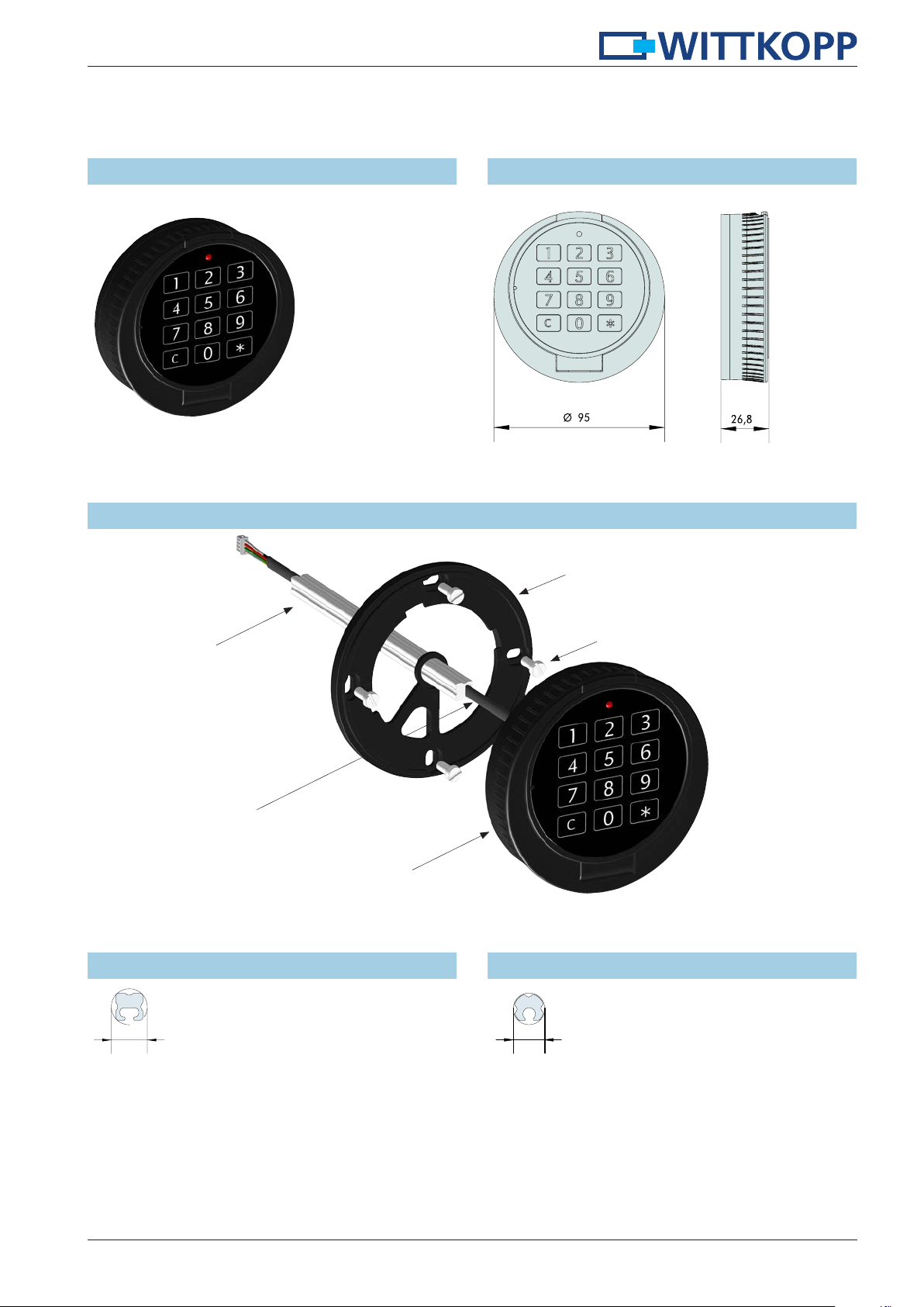
5 Installation input unit Primor RO
5.1 Input unit Primor RO 5.1.1 Dimensions Primor RO
5.2 Installation overview
5.2.1 Input unit Primor RO
Fixing ring for input unit
Spindle for
turnable input unit
Connection cable
Input unit
4 Cylinder screws M4 x 10
5.3 Panel hole Primor RO (turnable)
5.3.1 Spindle square 5.3.2 Spindle round
min. Ø 10.6 mm/max. Ø 11.4 mm
min. Ø 9 mm/max. Ø 11.4 mm
7

Installation instructions Primor
A
A
A
L
A
A15X
Achse in axialer Richtung
gegen verschieben sichern
A1
Achse in axialer Richtung
gegen verschieben sichern
5.4 Axis length calculation input unit Primor RO (drehbar)
5.4.1 In connection with Primor 100 5.4.2 In connection with Primor 2000
A
A
L
Spindle:
Debur the ends
L = A + 28 mm (tolerance -4 mm) L = A + 43 mm (tolerance -4 mm)
L
Spindle:
Debur the ends
5.4.3 In connection with boltwork
Secure the axis
against shifting in
axial direction
L
Spindle:
Debur the ends
L = X + A + 15 mm (+ axial hedge)
5X
8

Installation instructions Primor
78
78
4,3
4,3
41,5
41,5
4
4,3
78
4
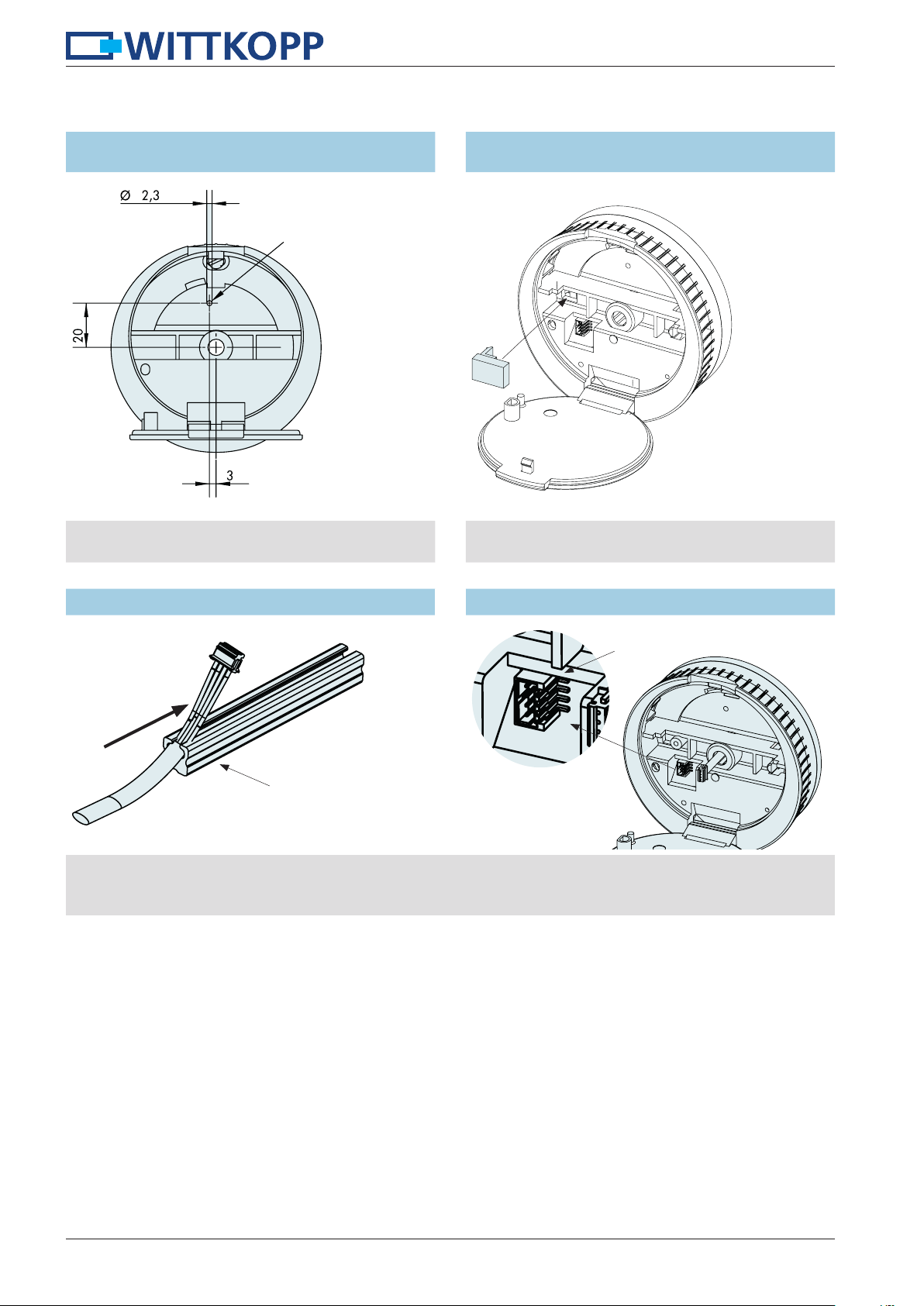
5.5 Mounting input unit
5.5.1 Drill pattern fixing with 4 threaded holes Primor RO
4 x Fixing position for M4
Hole center congruent with middle
axis of nut of the electronic lock
Opening for cable
• From the front 4 threaded holes M4 with sufficient thread depth and 1 through-hole (opening for cable/Spindle)
have to be drilled into the safe door.
• From the front the fixing ring has to be fixed with the enclosed cylinder screws M4 x 10.
5.5.2 Drill pattern fixing with 8 threaded holes Primor RO
41,5
4 x fixing positions for
screws M4
4,3
4,3
4,3
- oprionally Ø 41.5 mm
or Ø 78 mm
78
41,5
Hole center congruent with middle
axis of nut of the electronic lock
Opening for cable
• From the front 4 threaded holes M4 with sufficient depth thread and 1 through-hole (opening for cable/Spindle)
have to be drilled into the safe door.
• From the front the fixing ring has to be fixed with the enclosed cylinder screws M4 x 10.
5.5.2 Mounting input unit Primor RO
20°
Position 1
• Position 1: Mount the input unit with an angle of approx. 20° to the fixing ring.
Position 2
• Position 2: Turn the input unit to the right into position. The turning has to happen easily.
9
Installation instructions Primor
5.5.3 Input unit Primor RO (fixed)
Fixing ring with 4 threaded holes
Drill-hole Ø 3,4
mm in the safe door
to fix the input unit
• Fit input unit of approx. 20° (see 5.5.2), adjusting and
insert grub screw M3 x 6 or arrest pin.
5.5.4 Input unit Primor RO (fixed)
Fixing ring with 8 threaded holes
• Fit input unit of approx. 20° (see 5.5.2), adjusting and
insert clip.
5.5.5 Cable guidance Primor RO (drehbar) 5.5.6 Plug position Primor RO
Lock
Spindle
• Lead connection cable through the input unit.
• Insert the Spindle into the input unit from behind.
• Lead connection cable through the input unit and connect the plug.
10

Installation instructions Primor
82
6 Installation input unit Primor FL
6.1 Input unit Primor FL
(fixing on the inside)
6.2 Mounting input unit
6.2.1 Drill pattern Primor FL
Opening for cable:
Drill-hole min. Ø 8 mm/max. Ø 11.4 mm in
the safe door for connection cable
6.1.2 Input unit Primor FL
(fixing on the front)
6.1.3 Dimensions Primor FL
Emergency
Fixing position:
- Fixing on the inside: Through-hole
for screws M5
- Fixing on the front: Thread M3
• Fixing on the inside: 2 through-holes for screws M5 and 1 through-hole (opening for cable) have to be drilled into the safe door.
Fix the input unit with 2 screws M5 from behind.
• Fixing on the front: From the front 2 threaded holes M3 with sufficient depth and 1 through-hole (opening for cable) have to
be drilled into the safe door. Fix the input unit with 2 screws M5 from the front.
6.3 Mounting battery compartment
6.3.1 Battery compartment 6.3.2 Drill pattern battery compartment
78
41
36
47,5
• The battery compartment has to be fixed to the inside of the door. It is recommended to fix it in a way that it is accessible
without unscrewing the interior of the door.
• To avoid a short circuit/independent discharge, no connection between the inputs of the battery compartment and other
components may occur.
• Battery compartment can be fixed with the double sided tape or with the screws, which are included in the scope of delivery.
11

Installation instructions Primor
3
24
29
60
3
24
6.3.3 Battery sliding compartment 6.3.4 Drill pattern battery sliding compartment
29
43
53
60
• The battery sliding compartment has to be fixed to the inside of the door. It is recommended to fix it in a way that it is
accessible without unscrewing the interior of the door.
• To avoid a short circuit/independent discharge, no connection between the inputs of the battery sliding compartment and
other components may occur.
6.3.5 Plug position Primor FL
Lock
Battery
• The two 4-pin plug connection must be accessible at all times.
12

Installation instructions Primor
5,1
7 Installation input unit Primor FS
7.1 Input unit Primor FS 7.1.1 Dimensions Primor FS
7.2 Mounting input unit
7.2.1 Drill pattern Primor FS
Fixing position for screws M5
23
Opening for cable:
Drill-hole min. Ø 8 mm/max. Ø 11,4 mm for connection
5
46
• From the front 2 threaded holes M5 with sufficient depth and 1 through-hole (opening for cable) have to be drilled into
the safe door.
• Fix the input unit with the enclosed cylinder screws M5 from the front.
7.2.2 Cable guidance Primor FS 7.2.3 Plug position Primor FS
Connection cable lock
cable has to be drilled into the safe door
BatteryLock
Fixing screw
Bottom of case
Battery clip
Folding unit
• Lead connection cable of the lock and connection cable
of the battery behind the bottom of the case of the input unit.
13
Installation instructions Primor
17,3
41
66,5
17,3
41
66,5
8 Installation lock
Before mounting the lock the input unit has to be installed (see chapter 3 to 7).
Wittkopp electronic locks of the Primor series have got standard fixing points and can be mounted in all 4 directions (right-hand,
left-hand, up, down).
• The lock can be installed in all conventional safes.
•
Depending on the model there can be optional used more locking elements (e.g. angle with bolts) additional to the existing
holes of the bolt. Please make sure that the lock and the connections operate properly.
•
The electronic lock is maintenance free in normal domestic and office surroundings. After approx. 10,000 closures it is re-
commended to carry out a security and functional test of the electronic lock.
• For safety reasons it is not allowed to locate the electronic lock in the area where openings are (except Primor 100/2000).
• The electronic lock has to be protected against external attacks.
• It is recommended to protect all security relevant components of the high-security lock against tempering even when the
door is opened.
• Do not insert any lubricants or other substances into the electronic lock.
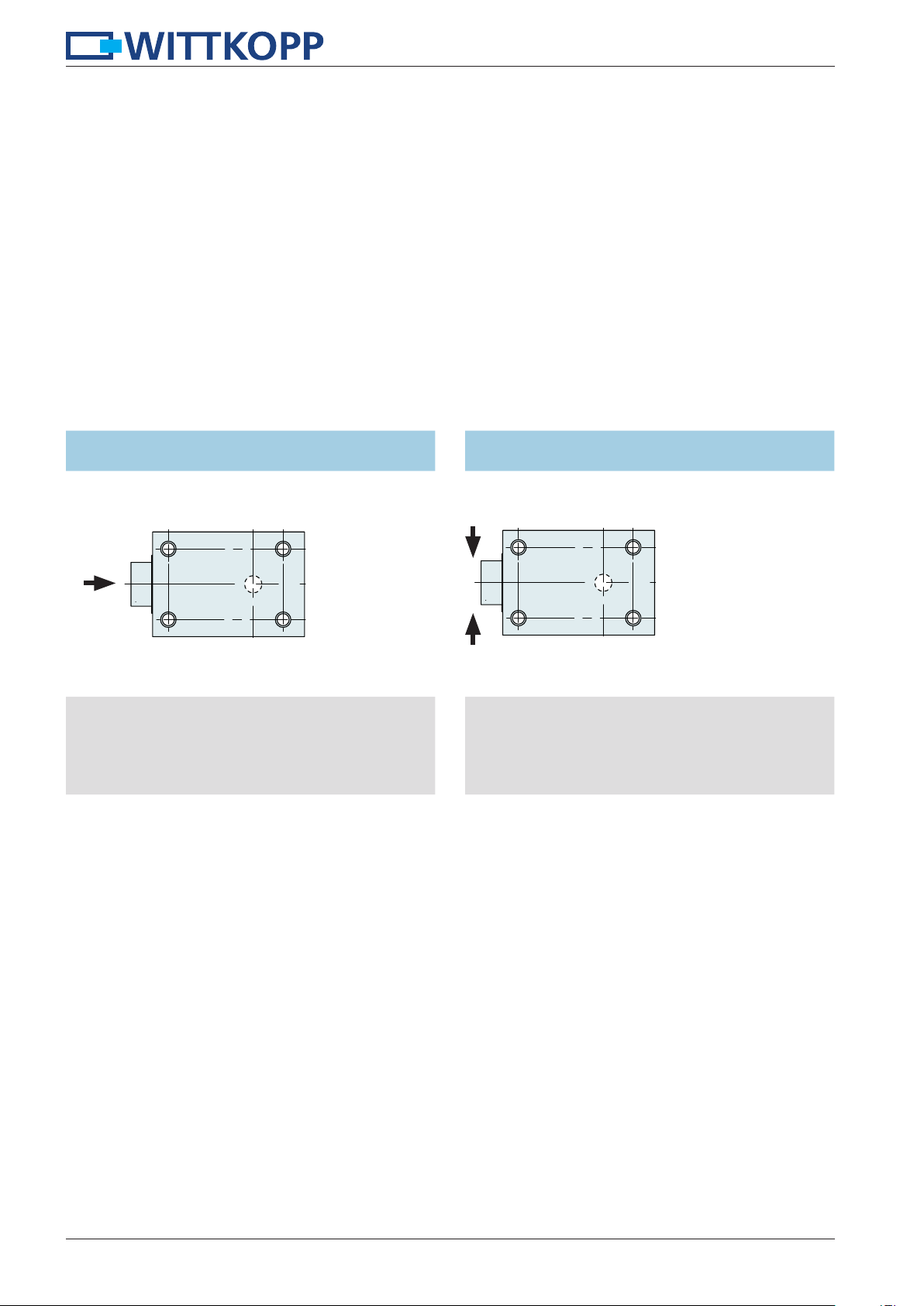
8.1 Constant bolt load
Primor 100/2000/3000/3010/3011
F
• The maximum and constantly bolt load against bolt
closing direction may not exceed the following limits::
Primor 100 2.5N
Primor 2000 2.5N
Primor 3000/3010/3011 2.5N
8.2 Bolt support load
Primor 100/2000/3000/3010/3011
F= 1000 N
F= 1000 N
• The load on the bolt must not exceed 1000 N.
14

Installation instructions Primor
Hub/Stroke 12
27
Platzbedarf/Required space
25
41
78
110
78
112,5
142
25
78
78
112,5
142
25
78
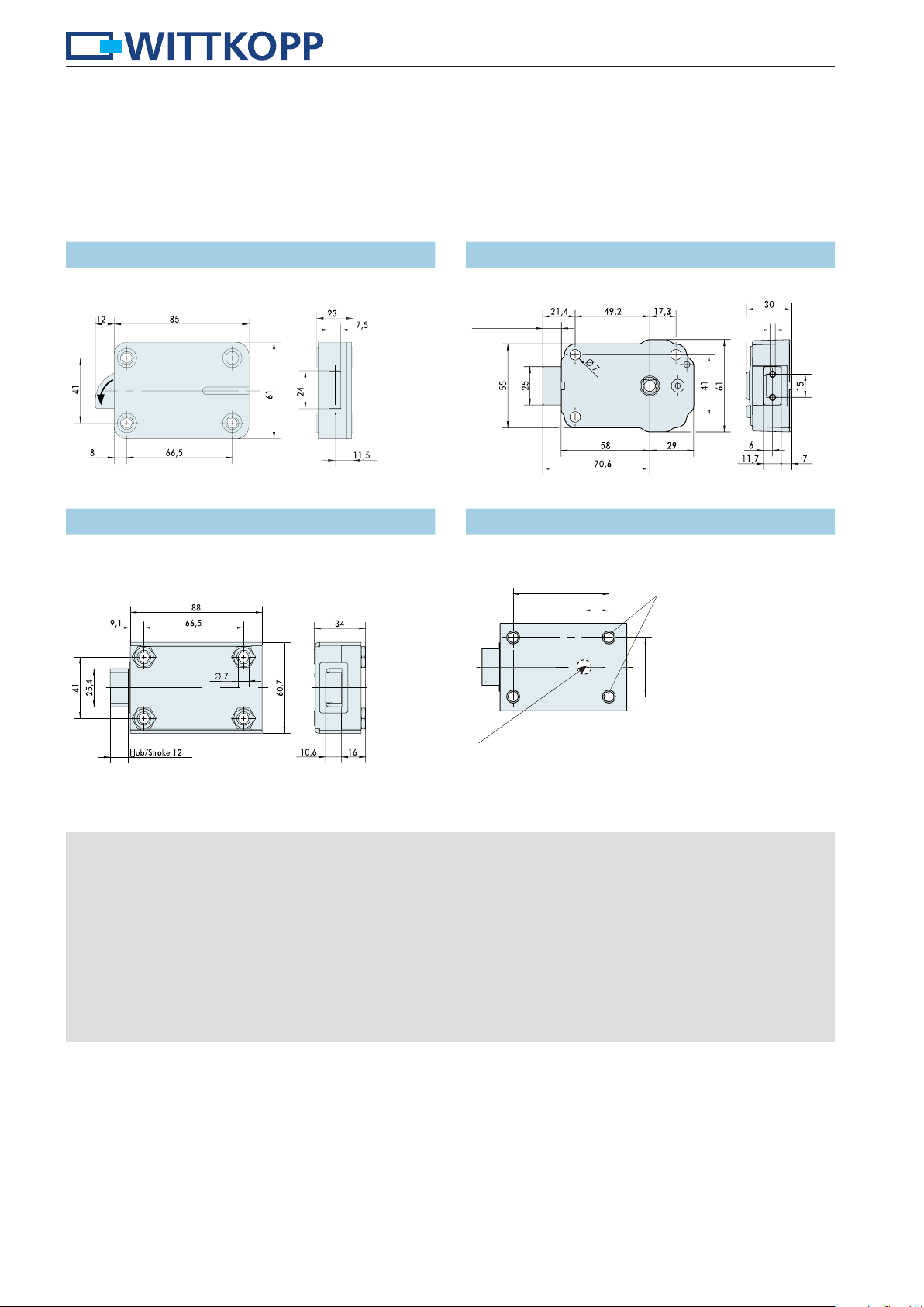
9 Mounting lock Primor 100
9.1 Dimensions lock Primor 100
60,7
Ø
4,5
25,4
15
9,1
58
88
66,5
25
41
Middle-axis of the nut has to be
congruent with the middle-axis of the
input unit
22
14 +12mm
9.1.1 Option extension latch 9.1.2 Option lock cover - screwed
6,5
Ø
142
25
9.1.3 Option lock cover - welded
(without anti-drilling plate)
110
9.1.4 Option lock cover - welded
(with anti-drilling plate)
66,5
112,5
If the lock is mounted without its lock case further installation guidelines have to be considered. Non-observance leads to
loss of VdS certification. A separate installation instruction no 9999-139-1 can be found on www.carl-wittkopp.com.
15

Installation instructions Primor
Hub/Stroke 12
102
Required space for bolt throw
9.2 Mounting lock Primor 100 - Schlossdecke anschraubbar
9.2.1 Dimensions lock Primor 100 - lock cover screwed
25
9,1
66,5
8
6,5
Ø
Platzbedarf für Riegelhub /
142
60,7
41
25,4
27
15
4,5
Ø
22
7
2,5
13
58
110
115
3
9
• 4 threaded holes M6 or 1/4" with depth min. 5 mm for fixing the key lock have to be drilled into the safe door.
•
Optional: Insert extension latches into the guiding pins at the back of the lock in the right direction and pull up the extension
latch that closes to the top.
• The lock case is put on top of the electronic lock.
• Lead the connection cable of the input unit through the square nut of the lock.
Attention: Don’t put the connection cable under tensile stress.
•
Afterwards the lock has to be stuck onto the spindle of the input unit that is already inside the door.
• The electronic lock has to be fixed with the screws included in the scope of delivery or cylinder screws M6 or 1/4" (at least
property class 8.8). The screw length should be 30 mm or longer so that a minimum thread length of 5 mm is achieved.
•
Independent loosening of the screws has to be avoided. Recommendation: put lock washers underneath the screw’s head.
• Turn the screws with a maximum turning force of 3.5 – 5 Nm.
• After mounting the bolt/extension latch must not be under tension.
• After the installation the lock’s bolt may not be loaded.
16

Installation instructions Primor
Hub/Stroke 12
102,1
Required space for bolt throw
Hub/Stroke
102
w
9.3 Mounting lock Primor 100 - lock cover welded
9.3.1 Dimensions lock 100 - lock cover welded
(without anti-drilling plate)
97027
8
25,4
78
15
60,7
7
4,5
Ø
22
13
58
110
115
2,5
25
Platzbedarf für Riegelhub /
142
3
9
9.3.2 Dimensions lock Primor 100 - lock cover welded
(with anti-drilling plate)
27
12
78
25,4
15
4,5
Ø
7
2,5
23
14
8
58
112,5
115
25
Platzbedarf für Riegelhub /
Required space for bolt thro
142
3
10
• Before welding the lock cover, the lock case has to be removed.
• When positioning keep the middle of the Spindle congruent with the input unit RO/RE.
•
Weld the lock case (if so with hardened manganese steel plate) with 4 welding seams, length 15-20 mm (position of the
welding seams on the corners of he lock case) to the inside of the safe door. Make sure that the lock cover (possibly with
hardened manganese steel plate) is fixed tightly onto the door.
• Welding distortion has to be avoided.
• Lead the connection cable of the input unit through the square nut of the lock.
Attention: Don’t put the connection cable under tensile stress.
•
The lock then has to be plugged onto the Spindle of the input unit, which is already in the safe door.
• Optional: Insert extension latches into the guiding pins at the back of the lock in the right direction and pull up the extension
latch that closes to the top.
•
The electronic lock has to be fixed with the 4 enclosed flat-headed screws M6 x 12 with the designated drillings of the lock
case in order that permanent foothold is guaranteed
• Turn the screws with a maximum turning force of 3.5 – 5 Nm.
• After mounting the bolt/extension latch must not be under tension.
• After the installation the lock’s bolt may not be loaded.
17
Installation instructions Primor
Hub/Stroke 12
66,5
10 Mounting lock Primor 1000
• When the swing bolt lock is used with another lock, the boltwork has to be set up, so that the swing bolt lock inevitably locks first.
11 Mounting lock Primor 1000/2000/3000/3010/3011
11.1 Dimensions lock Primor 1000 11.1.1 Dimensions lock Primor 2000
M4
11.1.2 Dimensions lock Primor 3000/3010/3011 11.1.3 Drill pattern locks Primor-Serie
Primor 1000/2000:
17,3
one drill-hole not necessary
41
Primor 2000:
Middle axis of nut of the electronic lock congruent with middle
of the input unit (Primor RO)/middle input unit lever (Primor RE)
• 4 threaded holes M6 or 1/4" (Primor 1000/2000 - 3 threaded holes) with depth min. 5 mm for fixing the key lock have to
be drilled into the safe door.
• The electronic lock has to be fixed with the screws included in the scope of delivery or cylinder screws M6 or 1/4" (at least
property class 8.8). The screw length should be 30 mm or longer so that a minimum thread length of 5 mm is achieved.
• Primor 2000: Lead connection cable through the lock and adjust the electronic lock on the spindle.
•
Fixing the lock with screws M6 or a comparable inch thread. Length and material application of the screw has to be selected
such as a secure long-term stability is guaranteed
• Turn the screws with a maximum turning force of 3.5 - 5 Nm.
•
Independent loosening of the screws has to be avoided. Recommendation: put lock washers underneath the screw’s head
• After mounting the bolt must not be under tension.
• After the installation the lock’s bolt may not be loaded.
18

Installation instructions Primor
60,7
Platzbedarf/required space
10,6
116
Hub / Stroke 12
11.2 Primor 3010 and 3011 with emergency lock
• Only emergency locks with the VdS class 2 may be installed.
• If electronic locks Primor 3010/3011 are installed without emergency locks, the installation has to be checked with the corresponding testing institute.
• For a safe functioning of the emergency opening the emergency locks should have a stroke of 12 mm.
• The emergency locks have to be protected from attacks from the outside.
11.2.1 Dimensions lock Primor 3010 - short unlocking lever with mechanical emergency lock
Installation example
9,1
41
25,4
66,5
Ø
7
Hub/stroke 12
Primor 3010
150
25,5
41
66,5
7
Ø
13
Mechanical emergency lock
N-1821
• If the emergency lock N-1821 is not used, the electronic lock Primor 3011 has to be used.
11.2.2 Einbaumaße Primor 3011 - short unlocking lever with mechanical emergency lock
Installation example
9,1 66,5
13,5
41
60,7
25,4
88
7
Ø
Primor 3011
34
+ 12 mm
6,8
4
M
15
34
58,3
41
60,7
66,5
88
• This installation has to be checked with the corresponding testing institute.
7
Ø
(X)
Mechanical
emergency lock
3
Area around the
unlocking lever
mustbe protected
especially.
25
19
Installation instructions Primor
11.2.3 Security notes Primor 3010/3011 – emergency lock
• For the emergency locks the general installation notes as described under point 8 apply.
• Due to security reasons it is recommended not to leave the key unattended in the lock.
• The keys have to be stored at a safe place and may only be accessible by authorized persons.
• When losing the key exchange the lock immediately.
• Make sure after each locking if the safe is locked.
11.2.4 Operating notes Primor 3010/3011 – emergency lock
• The lock may only be operated with the according keys. The insertion and opening attempts with other keys can lead to
internal damage.
• Never use force.
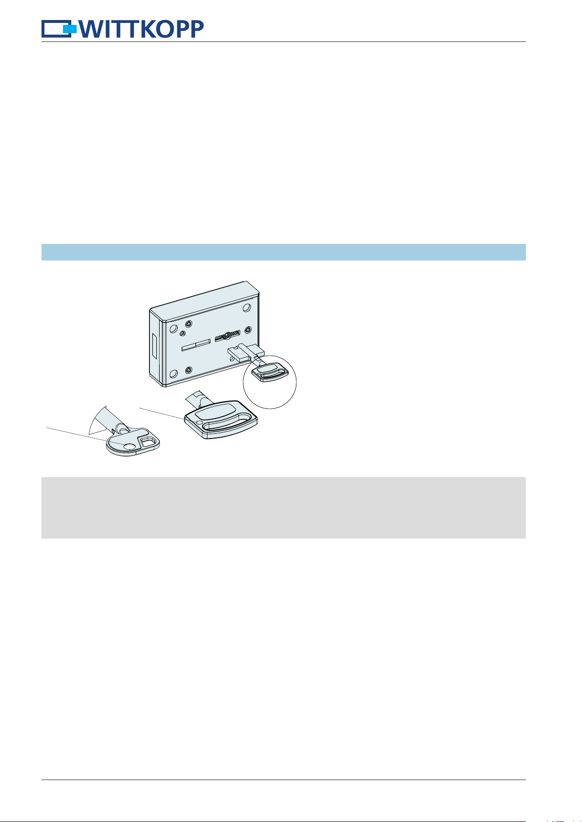
11.2.5 Operating the lock
Index
Index
• Insert key so that the marking on the key head is pointing towards the lock’s bolt
•
When using right-hand locks (turning axis towards the right) the key has to be turned clockwise. With left-hand locks
counter-clockwise.
•
Removing of the key is only possible when lock is closed. The key has to be turned to a tight end.
• When turning the key do not use force (no auxiliary means). If jamming occurs contact qualified personnel. .
20

Installation instructions Primor
12 Plug positions
12.1 Primor 100 12.2 Primor 1000
Input unit
Battery compartment/
signalbox
Input unit
12.3 Primor 2000 12.4 Primor 3000/3010/3011
Battery compartment/
Signalbox
signalbox
2
Input unit
• Connect the plug from/to the input unit into the outer plug position on the lock and check fixation. To loose the plug, carefully
lift and pull out.
•
Keep the connection cables away from sharp edges and moving parts of the boltwork, then fix them permanently.
• Plug the connection cables of the signal box (optional) into the position „signal box“ on the lock. For further installation notes
please see the separate installation instruction PrimorSignal/PrimorSignalPlus.
1
Input unit
13 External power supply
• The locks Primor 1000/2000/3000/3010/3011 can be power supplied externally by PrimorSignal plus.
• When using mains adapter as primary power supply, there is no voltage control of the inserted battery.
• Emergency power supply (optional): insert 1 x 9V block Alkaline.
13.1 PrimorSignal 13.1.2 PrimorSignal Plus
• Further Installation instructions and circuit diagram see separate installation instruction PrimorSignal/PrimorSignal Plus.
21

Installation instructions Primor
14 Functional test (when the door is open)
• Connect the power supply: connect the battery 9V block with the battery clip in the input unit or switch on the external power
supply.
• Enter the factory code:
Lock Primor 100:
1 – 2 – 3 – 4 – 5 – 6
Lock Primor 1000/2000/3000/3010/3011:
Level 5: 1 – 2 – 3 – 4 – 5 – 6
Level 15: 1 – 2 – 3 – 4 – 5 – 6 – 7
Re-enter the factory code when the power was switched off.
Primor 100/2000:
• Turn the input unit (Primor RO) or the opening lever (Primor RE) within 3 seconds into opening position. The lock is opened.
• Turn the handle into opening position.
• Closing shall be performed in reverse order.
Primor 1000:
• Within 3 seconds turn the boltwork’s handle into the opening position. The bolt swings in (has to happen easily). The lock is
opened.
• Turn the boltwork’s handle into the locking position. The swing bolt automatically folds out and locks. The lock is closed.
Primor 3000/3010/3011:
• The lock’s bolt opens automatically (has to happen easily). The lock is opened.
Turn the handle within 3 seconds into opening position.
• Turn the handle into locking position. The lock’s bolt closes automatically and blocks. The lock is closed.
15 Testing the system (programme 5)
Press every number once. A functional key will be confirmed by a double signal. A key that was not identified is confirmed by a long signal and the functional test is aborted. The system has to be checked.
1. Press and hold the key “5“ until the red LEDs flash permanently.
2. Press every key in its order of appearance.
5
123.......90
22

Installation instructions Primor
23

Installation instructions Primor
24
 Loading...