

Page 1
PENDULUM™
O
PERATOR’S MANUAL
Page 2

Page 3
WITTKE PENDULUM™
W/ MULTIPLEXED SYSTEM
OPERATOR’S MANUAL
Page 4

Liability
Labrie Enviroquip Group assumes no liability for any incidental, consequential, or other liability that
might result from the use of the information contained in this document.
All risks and damages, incidental or otherwise, arising from the use or misuse of the information
contained herein are entirely the responsibility of the user.
Although careful precaution has been taken in the preparation of this document, Labrie Enviroquip
Group assumes no responsibility for errors or omissions.
June 2014
Page 5

Page 6

Page 7

Table of Contents
Liability ........................................................................................ ii
Table of Contents ........................................................................ v
Introduction ................................................................................ 1
Introducing the WITTKE PENDULUM™ ............................................................................................................................................ 1
Product Overview ...................................................................................................................................................................... 2
Multiplexed System .................................................................................................................................................................. 4
To Contact Labrie Plus .................................................................................................................................................................... 5
In the U.S. ...................................................................................................................................................................................... 5
In Canada ...................................................................................................................................................................................... 5
Safety ........................................................................................... 7
Conventions ....................................................................................................................................................................................... 7
Basic Safety Notions ........................................................................................................................................................................ 7
Responsibilities .................................................................................................................................................................................. 8
Employer’s Responsibilities ................................................................................................................................................... 8
Employee’s Responsibilities ................................................................................................................................................... 9
Things to Do ....................................................................................................................................................................................... 9
Things to Avoid ................................................................................................................................................................................. 9
General Precautions ..................................................................................................................................................................... 10
Fire ...................................................................................................................................................................................................... 11
Safety Kits ......................................................................................................................................................................................... 12
Location of Safety and Informative Decals ........................................................................................................................... 12
Decals on Body ........................................................................................................................................................................ 13
Decals on Tailgate .................................................................................................................................................................. 19
Decals outside Cab ................................................................................................................................................................. 20
Decal on Lifting Arm .............................................................................................................................................................. 20
Decals inside Cab .................................................................................................................................................................... 21
Multiplex Switch Actuators (1) ........................................................................................................................................... 24
Multiplex Switch Actuators (2) ........................................................................................................................................... 25
Safety Features ............................................................................................................................................................................... 26
Third Eye Single Sensor Radar Detection System (optional) .................................................................................. 26
Back Up Alarm .......................................................................................................................................................................... 26
Body Safety Props ................................................................................................................................................................... 26
Tailgate Safety Prop ............................................................................................................................................................... 28
Securing Tailgate Safety Pins ............................................................................................................................................. 30
Camera System (optional) ................................................................................................................................................... 31
Tailgate Holding Valve .......................................................................................................................................................... 32
Safety Lockout Tests ..................................................................................................................................................................... 33
Hopper Door Proximity Switch .......................................................................................................................................... 33
Arms Partly Raised Proximity Switch in Packing Mode ............................................................................................. 33
Arms and Forks Fully Retracted Proximity Switches .................................................................................................. 34
Pendulum Packer In “Home” Position Proximity Switch .......................................................................................... 34
Top Door Fully Open Proximity Switch .......................................................................................................................... 34
Body Raised Proximity Switch ............................................................................................................................................ 35
Quick Reference Lockout Chart ......................................................................................................................................... 36
Cleanliness ....................................................................................................................................................................................... 36
Locking Out and Tagging Out the Vehicle ........................................................................................................................... 36
Shutting Down the Vehicle ........................................................................................................................................................ 37
Prior to Start Up .............................................................................................................................................................................. 38
Page 8

vi Table of Contents
Controls and Indicators ............................................................. 41
Labrie’s Multiplexed System ...................................................................................................................................................... 41
Warning and Caution Messages ........................................................................................................................................ 42
Hydraulic Oil Temperature Indicator (optional) ........................................................................................................... 48
Time and Date Indicator ....................................................................................................................................................... 48
Main Menu ................................................................................................................................................................................. 48
Control Panel ................................................................................................................................................................................... 57
Body Up Switch ........................................................................................................................................................................ 58
Body Down Switch ................................................................................................................................................................. 58
Pump Switch ............................................................................................................................................................................. 58
Tailgate Up Switch .................................................................................................................................................................. 59
Tailgate Down Switch ............................................................................................................................................................ 60
Mirror Light Switch (optional) ............................................................................................................................................ 61
Canopy Light Switch (optional) ......................................................................................................................................... 61
Strobe Light Switch (optional) ........................................................................................................................................... 61
Work Light Switch (optional) .............................................................................................................................................. 61
Auxiliary Control Power (optional) ................................................................................................................................... 61
Auto-Packing Switch (optional) ......................................................................................................................................... 62
Forks Width Switches (optional) ........................................................................................................................................ 62
Speed-Up Switches (optional) ............................................................................................................................................ 63
Top Door Switches (Roof Open/Roof Close) ................................................................................................................. 64
Tag Axle Switches (Tag Axle Up/Tag Axle Down) ....................................................................................................... 64
Hydraulic Alarm Switch (optional) .................................................................................................................................... 65
Packer Retracted Indicator Light ....................................................................................................................................... 65
Hopper Door Open Indicator Light .................................................................................................................................. 65
Arms Not Stowed Indicator Light ...................................................................................................................................... 65
In-Cab Packer Control Station ................................................................................................................................................... 65
Stop Push-Button (red) ......................................................................................................................................................... 66
Pack Push-Button (green) .................................................................................................................................................... 66
Retract Push-Button (yellow) .............................................................................................................................................. 66
Joystick Controls ............................................................................................................................................................................ 67
In-Cab Joystick ......................................................................................................................................................................... 67
Outside Dual Lever Joystick (optional) ............................................................................................................................ 68
Cab Dashboard ............................................................................................................................................................................... 69
Parking Brake ............................................................................................................................................................................ 69
Operating the WITTKE PENDULUM™ ............................................. 71
Daily Inspection .............................................................................................................................................................................. 71
Approaching the Vehicle ..................................................................................................................................................... 71
Visual Inspection ..................................................................................................................................................................... 71
Starting the Vehicle ................................................................................................................................................................ 72
Body Inspection Procedure ................................................................................................................................................. 72
Arm Inspection Procedure ................................................................................................................................................... 74
Inspection Sheet ...................................................................................................................................................................... 77
Right-Hand Side Driving Position (optional) ........................................................................................................................ 78
Position of the Lifting Arms ........................................................................................................................................................ 79
Collection Mode ...................................................................................................................................................................... 79
En Route ..................................................................................................................................................................................... 79
Overheight Caution ................................................................................................................................................................ 79
Units when not in Collection Mode .................................................................................................................................. 79
Exhaust Regeneration Process ........................................................................................................................................... 81
Collecting Refuse ........................................................................................................................................................................... 81
Planning your Route .............................................................................................................................................................. 81
Page 9

Table of Contents vii
Refuse Collection Procedure .............................................................................................................................................. 81
Packing Refuse ................................................................................................................................................................................ 84
Packing Refuse Using the Pack Button ........................................................................................................................... 84
Packing Refuse Using the Auto-Packing Mode ........................................................................................................... 85
Safety while Using the Packing System .......................................................................................................................... 85
Packer Not Working? ............................................................................................................................................................. 86
Unloading Refuse .......................................................................................................................................................................... 86
Preparing to Unload Refuse ................................................................................................................................................ 86
Unloading a WITTKE PENDULUM™ Unit ............................................................................................................................... 87
Cleaning of the WITTKE PENDULUM™ .......................................................................................................................................... 87
Preparing the Unit Before Departure .............................................................................................................................. 88
Clean-Up Procedure .............................................................................................................................................................. 88
Canopy Sweeper (optional) ................................................................................................................................................ 89
Shut-Down Procedure ................................................................................................................................................................. 90
Water Trap Bleed .................................................................................................................................................................... 91
Emergency Actions ....................................................................................................................................................................... 91
Hydraulic Oil Spill .................................................................................................................................................................... 91
Page 10

viii Table of Contents
Page 11
1
Introduction
The purpose of this manual is to introduce operators
to the operational procedures of the W
PENDULUM™ front-loader garbage truck. For
information regarding maintenance procedures, refer
to the related W
Manual.
Introducing the WITTKE
PENDULUM™
WITTKE PENDULUM™ units are front-load organics
collection vehicles used to pick up commercial
organics food waste. They can handle 3- to 6-yard
containers and collect 2 64- or 96-gallon carts at a
time. Once the body is full, all its content is unloaded
at a waste management landfill or other appropriate
site (e.g. transfer station, incinerator, recycling
station). These vehicles are designed to be operated by
only one person at a time, and they use a series of
hydraulic, pneumatic, mechanical, and electrical
systems to perform their work routine.
ITTKE PENDULUM™ Maintenance
ITTKE
3
W
ITTKE PENDULUM™ units are also equipped with the
multiplexed system designed to make the collection
process more efficient and the troubleshooting process
more orderly and manageable.
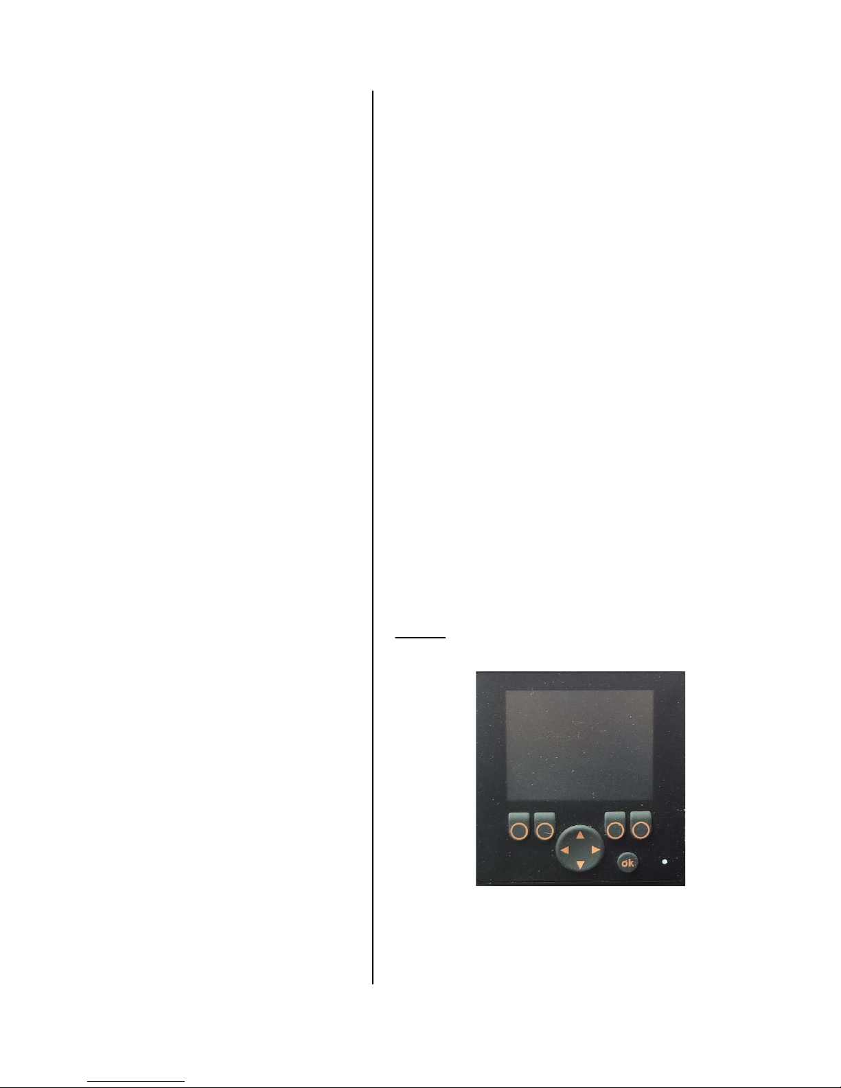
Figure 1-1
Multiplexed system display
Page 12
2 Introduction
Product Overview
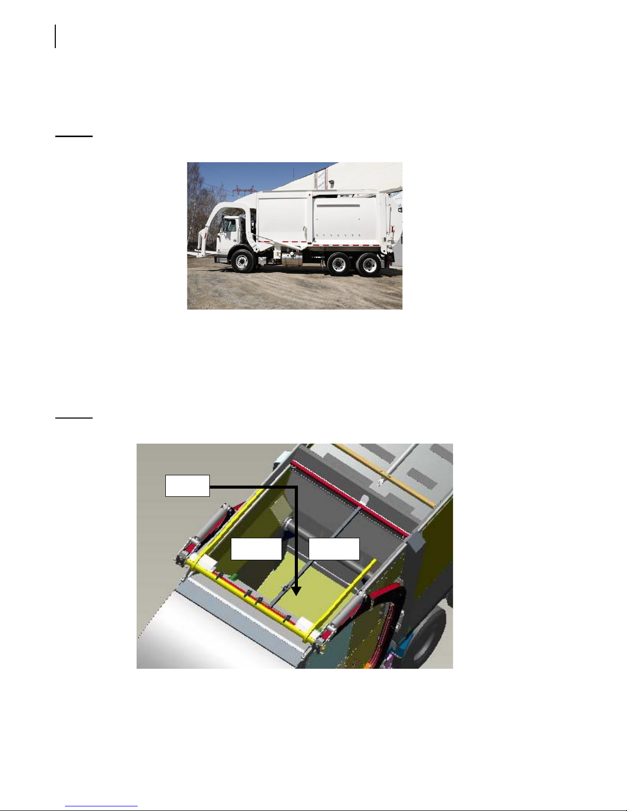
WITTKE PENDULUM™ units are fitted with a set of swing arms and forks to perform collection of
organics food waste.
Figure 1-2
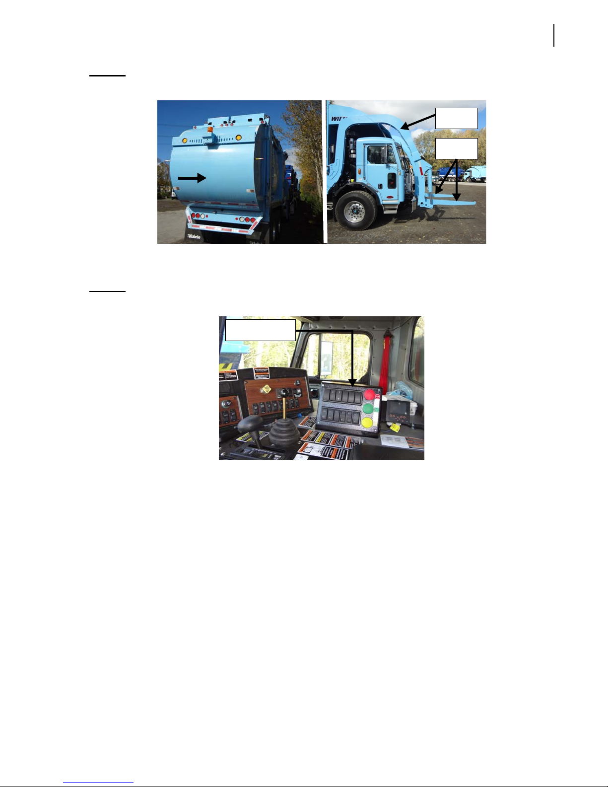
Body’s main components are the hopper (see Figure 1-3), the pendulum packer (see Figure 1-3), the
tailgate (see Figure 1-4), and the swing arms and forks (see Figure 1-4).
The hopper is the area of the body where the food waste is dumped. The pendulum packer is the
piece of equipment that pushes the waste into the body. The tailgate is the rear door that prevents
food waste from exiting the body during collection. At a landfill, the tailgate is raised to enable the
discharge of the waste.
Figure 1-3
The W
ITTKE PENDULUM
Hopper and pendulum packer
™
Packer
Hopper
Hopper
Page 13
Introduction 3
Figure 1-4
In the cab, you will find the control panel, the monitor, the joystick, and all the switches that control
most of the truck’s functions (see Figure 1-5).
Figure 1-5
Tailgate (left); Arms and forks (right)
W
ITTKE PENDULUM
™ cab
Control panel
Arm
Forks
The WITTKE PENDULUM™ comes with a series of key features:
Body walls made up of 100% Hardox 450 steel delivering ultimate strength at the lowest possible
body weight
Hopper sides and floor made up of Hardox 400 steel
Tip-to-dump body
Arm lifiting capacity: 10,000 lbs
Packer is of Pendulum type
Hopper funnel has full front slope to avoid organic material stack up
Canopy has gutters to drive liquids into the hopper and not on the cab
Curbside covers giving access to Pendulum cylinders
Tip-to-dump cylinder maintenance trap on hopper front
Liquid tight hopper
Packer cylinders not exposed to organics
No debris behind the packer
Page 14

4 Introduction
Optional features:
• Canopy sweeper (if no cart tipper on fork torque tube)
• Adjustable hydraulic forks (if no cart tipper on fork torque tube)
• CNG roof: 60 and 75 DGE
• CNG chassis (depending on available room)
• Outside controls
• Washout tank (depending on available room)
• Tool box (depending on available room)
• Chassis modifications and additional axles (depending on available room)
• Digiload scale system
Multiplexed System
The WITTKE PENDULUM™ is equipped with an electronic monitoring system called the multiplexed
system.
The Multiplexed system used by Labrie is a CAN-based system that integrates a display monitor, a
control panel and a number of electronic controllers. This whole system has been designed to help
you operate your unit in an efficient and easy way. See Labrie’s Multiplexed System on page 41 for
more details on this.
IMPORTANT: Multiplexed system-equipped WITTKE PENDULUM™ units must be operated by only one person.
Page 15

To Contact Labrie Plus
In the U.S.
Address: 1981 W. Snell Road
Oshkosh, WI 54904
Toll Free: 1-800-231-2771
Telephone: 1-920-233-2770
General Fax: 1-920-232-2496
Sales Fax: 1-920-232-2498
Parts and warranty: During business hours, 7:00 AM to 7:00 PM Central Standard Time
Technical Support Service: Available 24 hours
Introduction 5
In Canada
Address: 175 Route du Pont
St-Nicolas, QC G7A 2T3
Toll Free: 1-877-831-8250
Telephone: 1-418-831-8250
Service Fax: 1-418-831-1673
Parts Fax: 1-418-831-7561
Parts and warranty: During business hours, 8:00 AM to 5:00 PM Eastern Standard Time
Technical Support Service: Available 24 hours
Website: www.labriegroup.com
E-mail: [email protected]
IMPORTANT: For technical support and parts ordering, the serial number of your vehicle is required. Therefore,
Labrie Enviroquip Group recommends to keep record of the information found on the VIN plate,
which is located in the cab.
Page 16

6 Introduction
Page 17
Safety
Safety is always of prime importance when operating
any type of equipment. All operators working with the
W
ITTKE PENDULUM™ front-load organics collection
truck must be aware of the safety practices and features
detailed in this section.
Conventions
2
Danger!
Warning!
Caution!
Basic Safety Notions
The following safety notions are related to the use of
the W
ITTKE PENDULUM™. It is important to point out
that the safe use of the vehicle remains the user’s
responsibility. He must heed all safety notions
explained in this manual and on the decals found on
the vehicle.
Indicates a hazardous situation which, if
not avoided, will result in serious injury or
death.
Indicates a hazardous situation which, if
not avoided, could result in serious injury
or death.
Indicates a hazardous situation which, if
not avoided, may result in minor or
moderate injury.
Danger!
Always be aware of the vehicle’s
surroundings to make sure that no
pedestrians, passersby, bystanders, or
other people or vehicles are in any way
exposed to any danger caused by the
use of the W
ITTKE PENDULUM™.
Page 18

8 Safety
Danger!
Never get in the hopper area when the engine is running.
Only authorized personnel may do so following a lockout/tagout procedure (see Locking
Out and Tagging Out the Vehicle on page 36).
Responsibilities
Safety is everybody’s responsibility. Both employer and employee must play their part to ensure the
safety of the operator, the vehicle, and its immediate surroundings.
Employer’s Responsibilities
It is the responsibility of the employer:
To ensure that the W
and codes, including all applicable regulations, the Occupational Safety and Health Act (
and the American National Standards Institute (
To ensure that employees are qualified for operating the vehicle and its equipment, and that they
all take safety measures before using them.
To properly maintain all mobile equipment to meet all provincial/state and federal safety
standards.
ITTKE PENDULUM™ is operated in accordance with all safety requirements
OSHA),
ANSI).
To supply adequate instructions and training for the safe use of the vehicle and its equipment
before assigning an employee to such vehicle.
To keep the vehicle maintained and properly adjusted to meet the manufacturer’s standards and
recommendations. For help or for more information, please contact the manufacturer or any of its
authorized representatives.
To keep records of all vehicle breakdowns and malfunctions, as well as any inspection and
maintenance.
To ensure that all failures or malfunctions that may be affecting the safe use of the vehicle are
repaired before the vehicle is put back into operation.
To meet the appropriate lighting requirements for night shift work (if permitted).
To regularly accompany the vehicle operator and take measures to ensure the smooth and safe
operation of the vehicle.
To make sure that the backup alarm works properly when the vehicle is in reverse.
To take necessary measures to correct any damage or malfunction reported by any employee.
To establish a “lockout/tagout” procedure and ensure its application any time inspection, repair
or maintenance is performed on the vehicle, regardless of whether it takes place on the road or in
the garage.
Page 19

Employee’s Responsibilities
It is the responsibility of the employee:
To enforce all safety measures to meet the requirements established by the employer.
To operate the W
To perform routine daily unit inspections.
To make sure that nobody is near the vehicle before activating any of the controls, and to be
prepared to stop at any indication of possible danger.
To immediately report any damage or malfunction of the vehicle to the employer or supervisor.
IMPORTANT: Do not use damaged equipment.
ITTKE PENDULUM™ only after having received proper instructions and training.
Things to Do
Inspect the body and all systems at the beginning of each day.
Make sure that the area is clear of any people or possible obstructions.
Safety 9
IMPORTANT: Be extremely cautious in areas where small children may be present.
Wear safety glasses and footwear, gloves, and any other safety equipment when loading and
packing refuse.
Check mirrors, windows, lights, and monitor equipment are clean and adjusted properly.
Use caution when driving with an unevenly distributed load.
Inspect for overhead hazards (e.g. power lines) prior to lifting arms, hoisting body or climbing on
it.
Always use the body safety prop when servicing under the body.
Always use the tailgate safety prop before entering the area between the main body and the
tailgate.
Obey all warning and operation stickers.
Things to Avoid
Do not operate any vehicle while under the influence of alcohol, narcotics or other intoxicants.
Do not talk on a cell phone or listen to loud music while driving.
Do not wear jewelry or loose clothing.
Do not leave the vehicle before it is brought to a complete stop and work brake or parking brake is
applied.
Do not enter the hopper or main body unless the engine is shut off, the key is removed and there is
an out-of-service tag on the steering wheel (see Locking Out and Tagging Out the Vehicle on
page 36).
Do not hoist the body on uneven ground.
Do not back up the vehicle when the body is raised.
Page 20

10 Safety
Do not drive with the tailgate fully open unless it is to unload refuse at the landfill.
Do not use the body safety prop to prop a loaded body.
General Precautions
Danger!
Operators must adhere to the following precautions at all times. Failure to do so may
result in vehicle and/or property damage, personal injury, or even death.
It is the employer’s responsibility to ensure that only qualified employees are assigned to operate this
vehicle.
Read and make sure that you fully understand this manual and all safety decals before operating
this vehicle. Maintenance personnel must also read and understand the Maintenance Manual for
this vehicle. In case of doubt, ask a supervisor for clarifications.
Before every work day, inspect the body, the packing system, and any system that might
compromise public and/or operator safety.
Verify that the accelerator pedal, the steering wheel, mirrors, brakes, and turn signals are in good
working order.
When driving the vehicle, keep both hands on the steering wheel at all times.
Stop the vehicle completely and put on the parking brake before leaving the driving position.
When the vehicle is parked, the parking brake must be applied.
Before activating both arms, operators shall make sure that people and obstructions are far away
from the vehicle. Operators must be able to stop these arms at all times.
ITTKE PENDULUM™ vehicles are primarily designed to be operated by only one person. However,
W
if Labrie Enviroquip Group customers elect to operate the vehicle with more than one worker,
additional safety items shall be installed to protect the co-worker from hazardous situations.
IMPORTANT: In such cases, Labrie Enviroquip Group must be informed of every and all units that will be operated
by more than one worker. Labrie Enviroquip Group will then determine and supply, at the
customer’s expense, the required safety items. For additional information, please contact LabriePlus
at 1-877-831-8250 in Canada or 1-800-231-2771 in the U.S.
Do not operate this vehicle if there are any signs of damage or incomplete repairs.
Report any doubts that you might have and any safety service requirements regarding this vehicle
to a supervisor.
When removing nylon locknuts, always replace them by new ones.
Never drive this vehicle with the tailgate unlocked.
For any work (including cleaning and inspection) that has to be done between the body and the
chassis, always use the body safety prop. Also, the vehicle must be on level ground.
Before opening and closing the tailgate and/or raising the body, make sure that there is no one
behind the vehicle.
Page 21
Safety 11
Do not get into the hopper compartment or try to repair anything behind the pendulum packer
when it is moving or when the hydraulic pump is still running. Personnel authorized to get into the
hopper must first lock out and tag out the vehicle, as required by the employer. For more
information, see Locking Out and Tagging Out the Vehicle on page 36.
Never, under any circumstances (maintenance or otherwise), stand underneath a loaded body.
Warning!
Warning!
Warning!
Warning!
Do not operate the lifting arms until you have been fully trained, and have read and
understood both the Operator’s Manual and the Maintenance Manual supplied with this
unit.
Make sure that all people and obstructions are sufficiently cleared from the lifting arms
before moving them. Failure to do so may result in unit and/or property damages,
personal injury or death.
Make sure there is enough clearance between raised container and overhead power
lines. The lifting arms or the container must not come in direct contact with the electrical
cables for the power to go through the unit. If the unit comes in contact with a power
line, stay in the cab and keep away from any metal parts.
Always retract forks and raise lifting arms before circulating with the vehicle. Failure to do
so will result in unit and /or property damage, severe injury or even death.
Caution!
Caution!
Fire
The employer must inform and train all personnel on the measures that must be taken in case of a
vehicle and/or loaded body catching fire.
Anytime a loaded vehicle is brought inside a garage, fire extinguishers shall be close at hand.
Always keep the optional clean-out door closed when operating the lifting arms.
Otherwise, damage could occur to either hydraulic cylinder or trap door.
Make sure the hopper roof is fully opened before lifting a container.
Page 22
12 Safety
The employer must also inform employees of an appropriate place to unload the body near the
maintenance facility (preferably away from traffic, surface drains, and ditches).
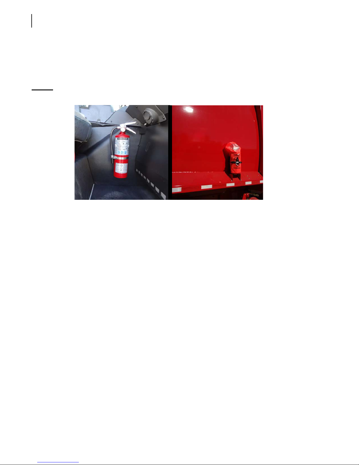
W
ITTKE PENDULUM™ vehicles are equipped with a 5-lb fire extinguisher, which is located inside the
cab. A 20-lb fire extinguisher may also be installed as an option. Each fire extinguisher must be
checked regularly by qualified personnel.
Figure 2-1
5-lb fire extinguisher (left); 20-lb fire extinguisher (right)
Safety Kits
A first aid kit, a flare kit and a triangle kit are options that may come with the truck.
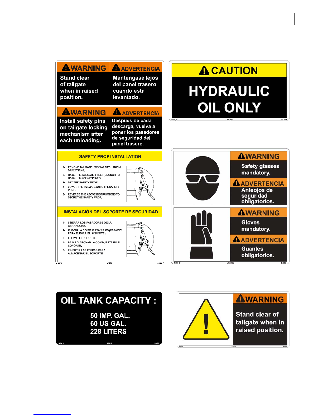
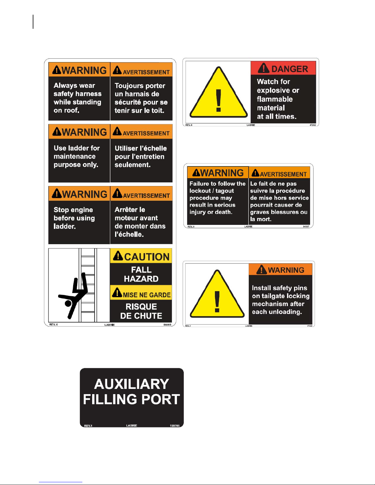
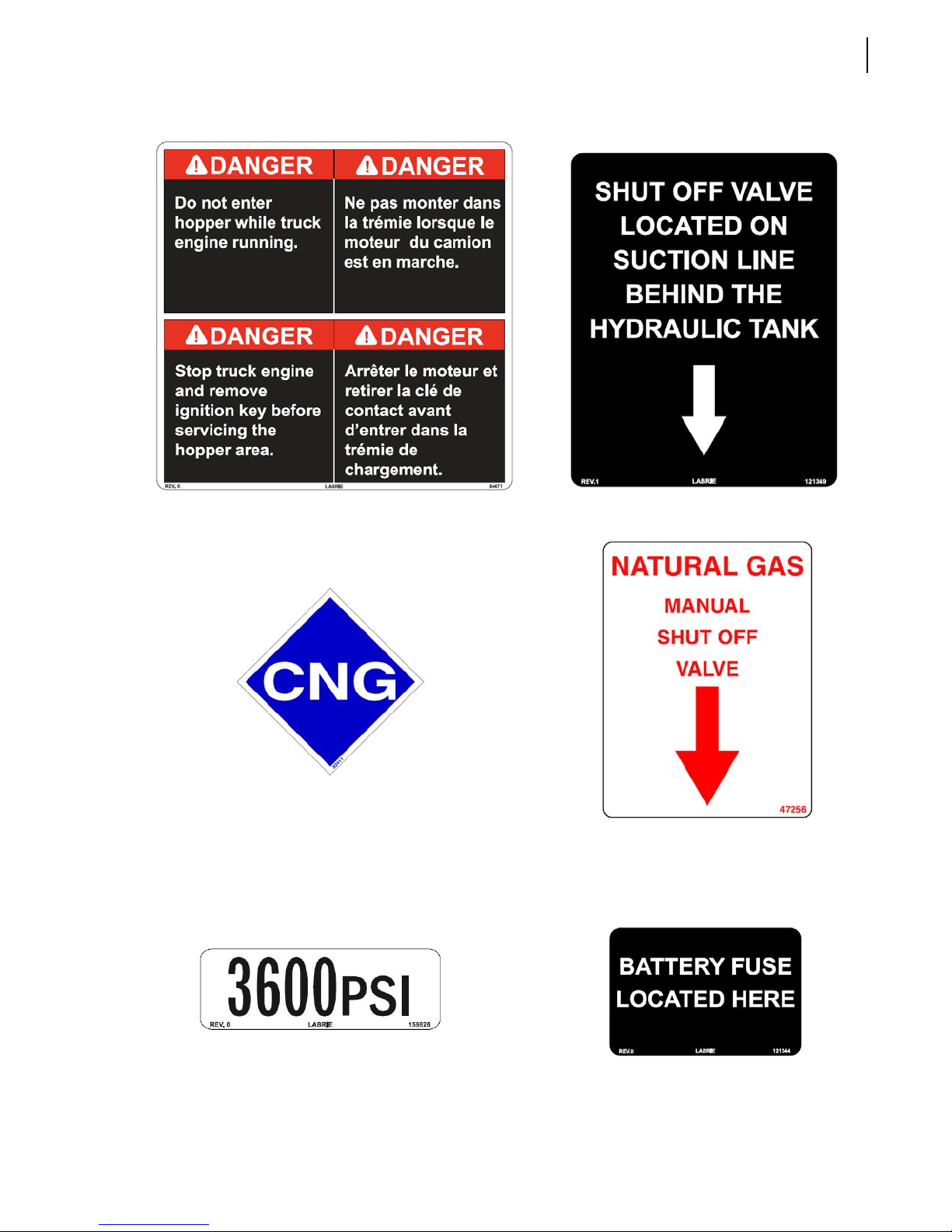
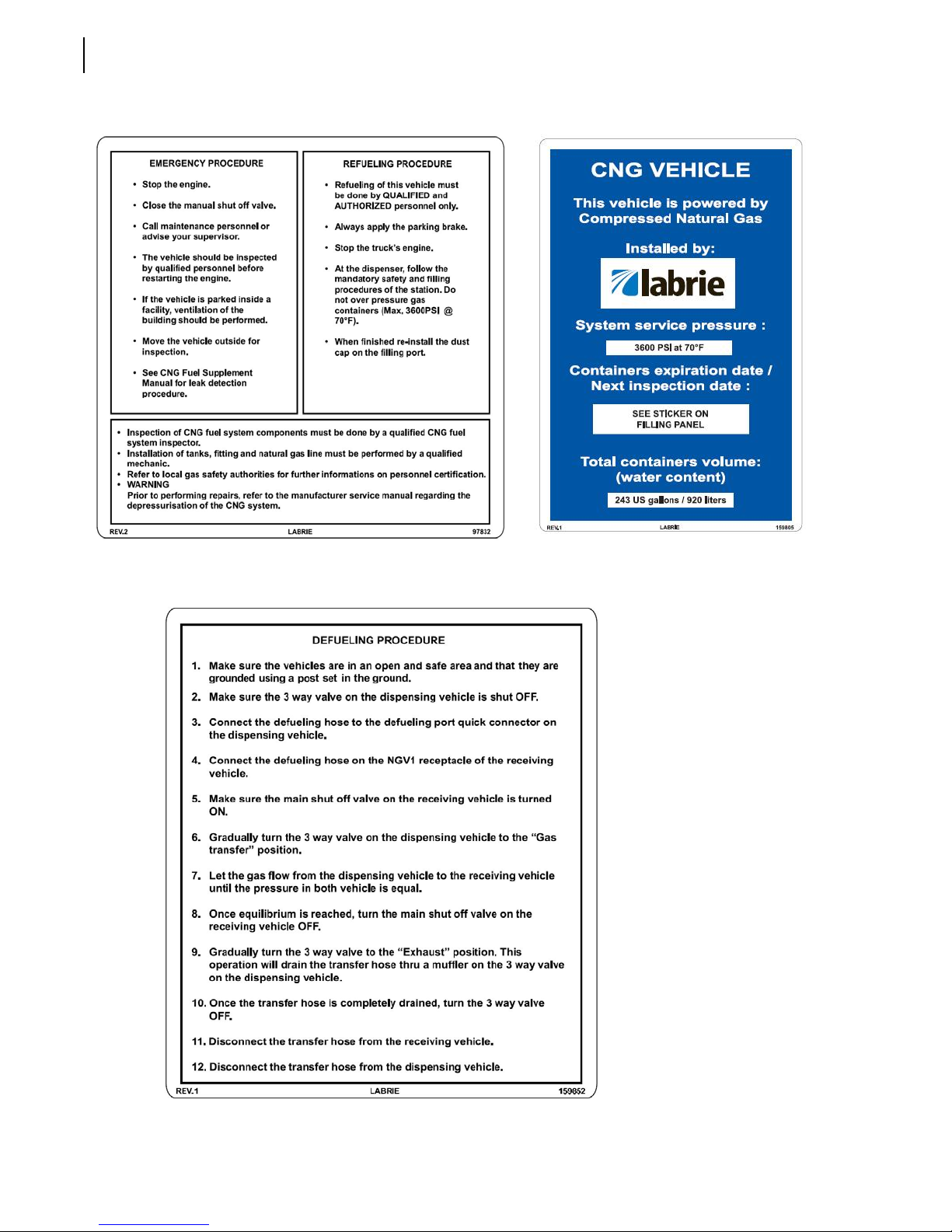
Location of Safety and Informative Decals
Pay careful attention to all safety, warning and informative decals while working in and around the
W
ITTKE PENDULUM™. Keep your decals clean and in good condition at all times. For replacement
decals, please call LabriePlus. Decals may vary from one unit to another depending on the options
and features installed on the unit. The following is an illustrated list of decals, but not limited to.
Page 23
Decals on Body
Safety 13
47304
120989 - English/Spanish
79846 - English/French
84459
84458 - English/French
93490 47268
84470
84469 - English/French
120974 - English/Spanish
79836 - English/French
Page 24
14 Safety
47282
120983 - English/Spanish
79842 - English/French
84465
84466 - English/Spanish
84367
84368 - English/Spanish
47422
121033 - English/Spanish
79853 - English/French
159785
Optional
Page 25
Safety 15
84471
84472 - English/Spanish
32411 47256
Optional
121349
84419 - Spanish
159761 - French
Optional
159828
Optional
121344
Page 26
16 Safety
97832 84447 - Spanish
159759 - French
Optional
159805 159807 - Spanish
159806 - French
Optional
159852
58704 - French
Optional
Page 27
Safety 17
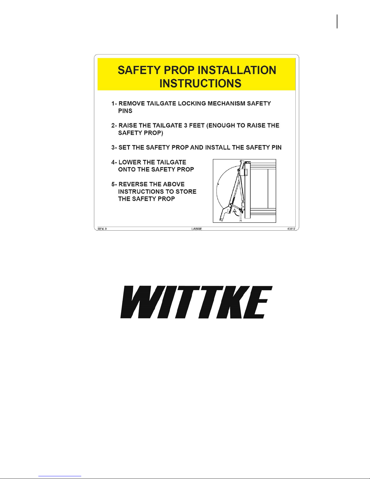
43817
121032 - English/Spanish
79868 - English/French
121235
Page 28
18 Safety
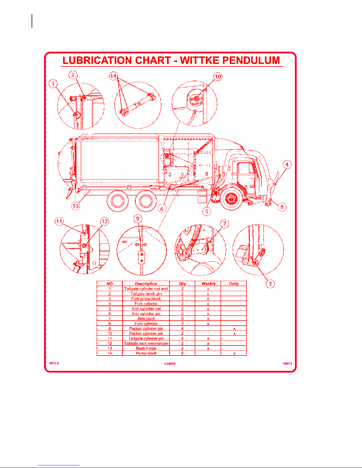
164672
164676 - Spanish
164675 - French
Page 29
Safety 19
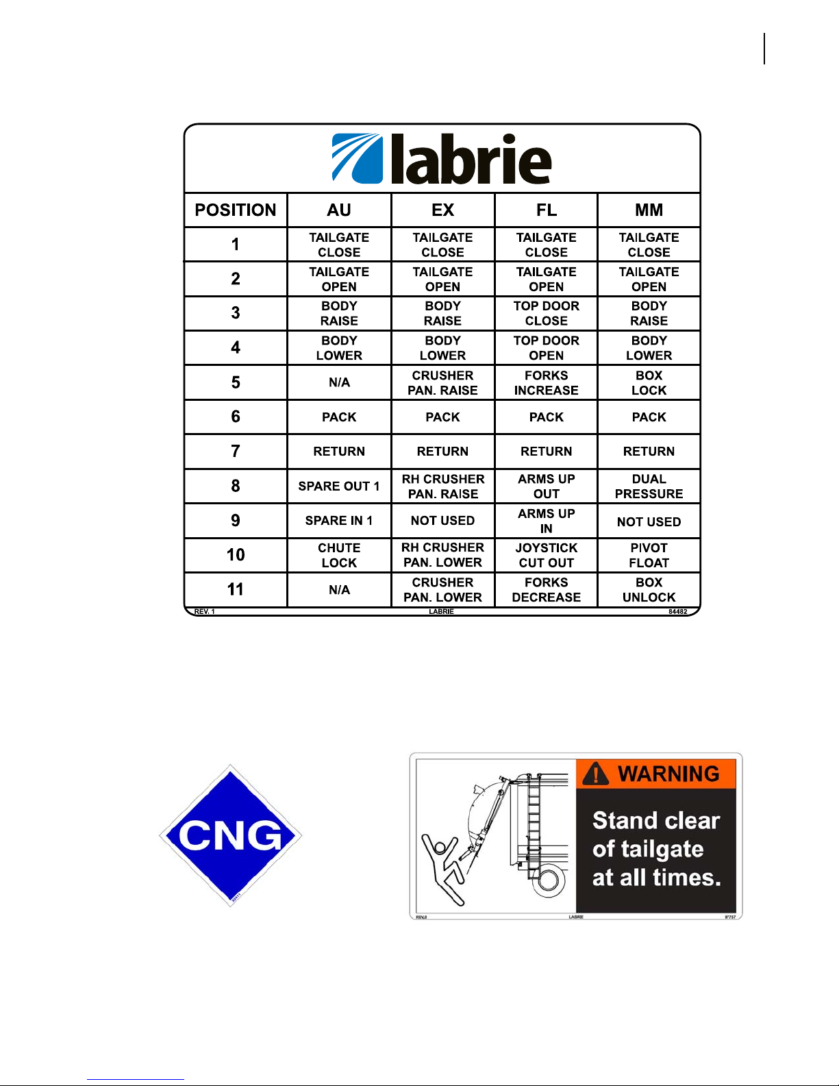
84482
Decals on Tailgate
32411
Optional
MATERIEL : PERMA-GRIP
97757
97759 - English/Spanish
97758 - English/French
Page 30
20 Safety
Decals outside Cab
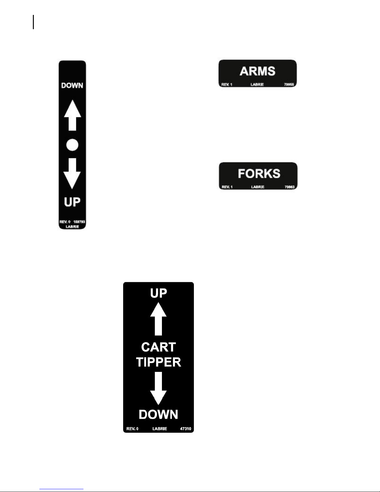
79955
79956 - French
Optional
159793
159794 - French
Optional Optional
Decal on Lifting Arm
79963
79964 - French
47310
47311 - French
Optional
Page 31
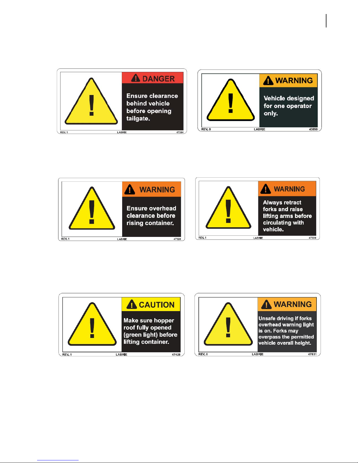
Decals inside Cab
Safety 21
47284
120980 - English/Spanish
79843 - English/French
47328
120972 - English/Spanish
121013 - English/French
43850
84001 - English/Spanish
79822 - English/French
47330
120975 - English/Spanish
121018 - English/French
47428
120986 - English/Spanish
121036 - English/French
47831
121020 - Spanish
121031 - English/French
Page 32
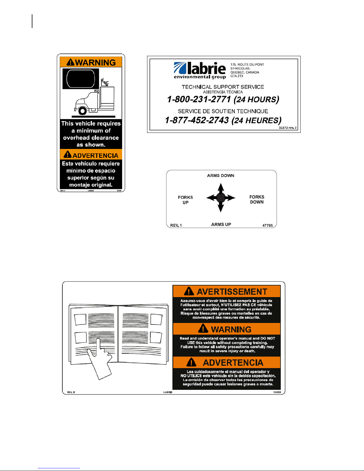
22 Safety
32272
84189
84188 - English/French
47705
120994 - English/Spanish
121034 - English/French
104539
84032 - English/Spanish
84031 - English/French
Page 33
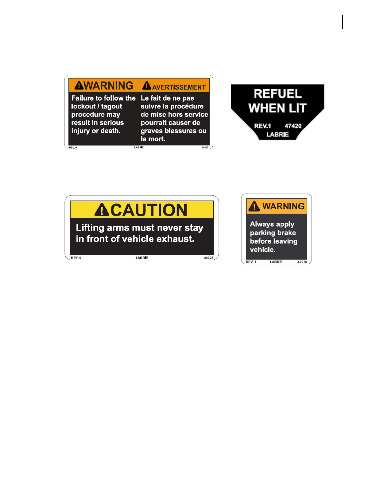
Safety 23
84367
84368 - English/Spanish
84325
84327 - English/Spanish
84326 - English/French
47420
84420 - Spanish
159755 - French
47276
84303 - English/Spanish
79840 - English/French
Page 34
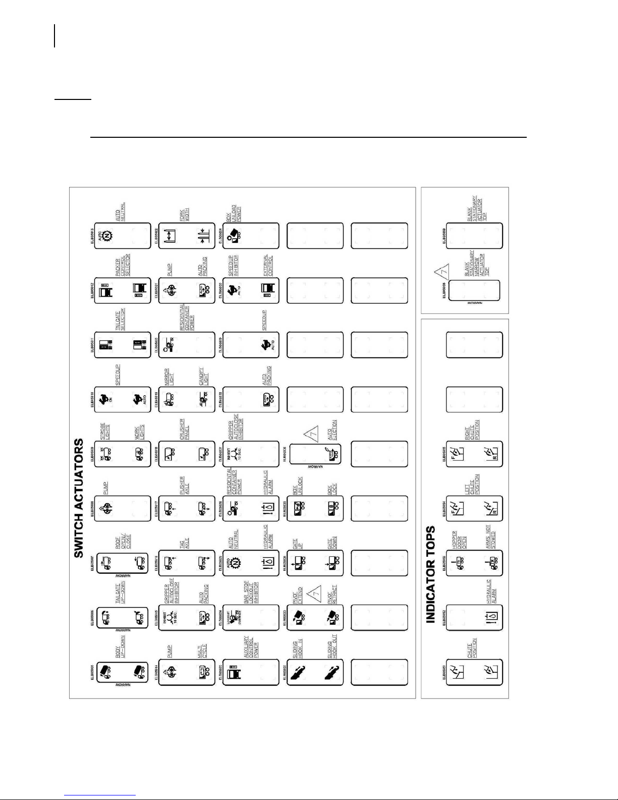
24 Safety
Multiplex Switch Actuators (1)
NOTE: Multiplex switch actuators and their location on the control panel vary according to the
options installed on the unit.
Page 35
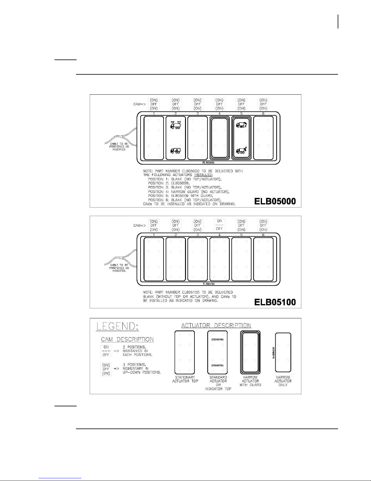
Multiplex Switch Actuators (2)
NOTE: This illustration and the preceding one were taken from the PDF file no 159535.
Safety 25
NOTE: 1- All symbols to be negative lens.
2- Electronic file for the symbols available on request from Labrie Enviroquip Group only.
Page 36
26 Safety
Safety Features
Third Eye Single Sensor Radar Detection System (optional)
This system will sound a buzzer when an obstruction is detected behind the unit. Consult the OEM
for more information.
Back Up Alarm
The back up alarm sounds when the transmission is put into reverse or when the tailgate opens.
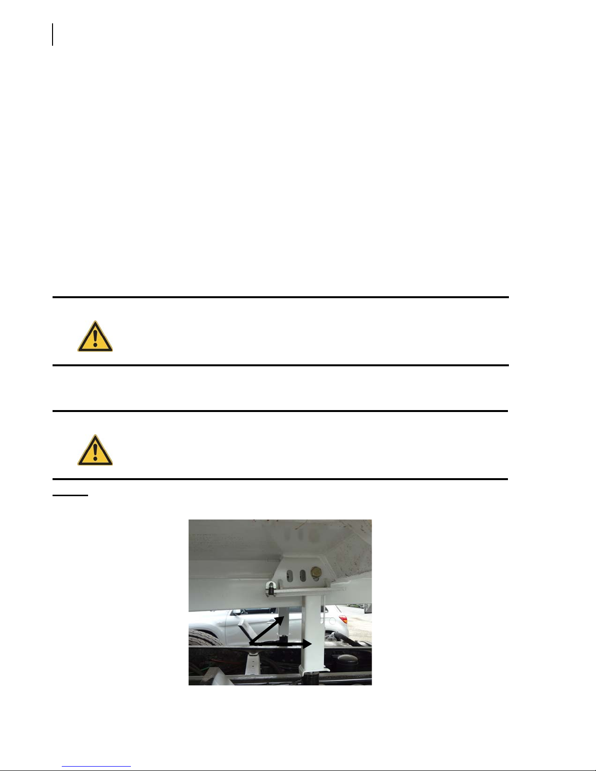
Body Safety Props
The body safety props must be set when any work is performed under a lifted body.
Safety props ensure that heavy body parts will not move inadvertently.
Warning!
Setting the Body Safety Props
The safety props ensure that an empty body will not lower when you are working underneath it.
Danger!
Figure 2-2
Body safety props
Always unload the body before setting the body safety props.
Always set the body safety props when performing maintenance underneath a raised
body. Failure to do so may result in severe injury, or even death.
Page 37
To set the body safety props:
1. Make sure that there is enough clearance above the body to raise it safely and that the truck is on
safe level ground.
2. Start the truck.
3. Turn the pump switch on.
4. Raise the body until both safety props can be moved into position.
IMPORTANT: Do not raise the body higher than what is required for the props.
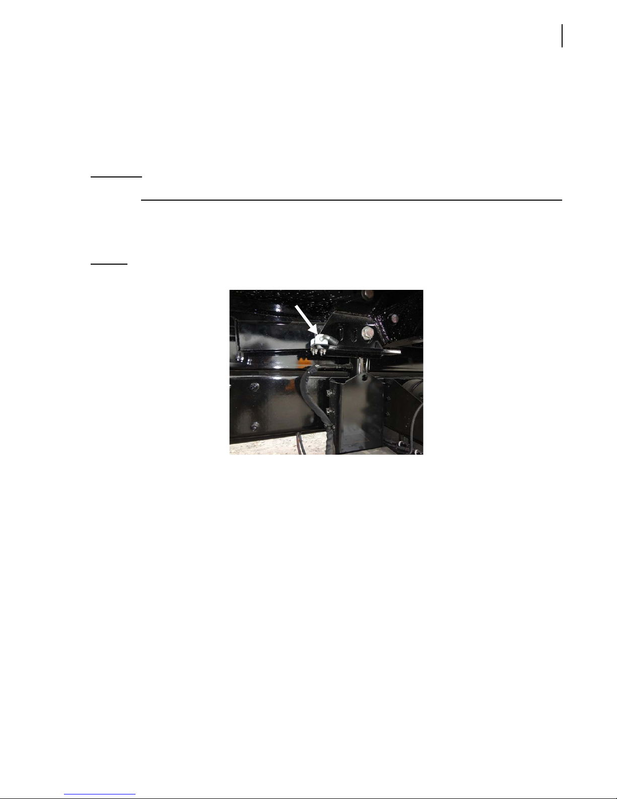
5. Release one of the safety props by pulling its latch towards you (see Figure 2-3), and position the
prop adequately (see Figure 2-2).
The safety prop must take place around the cylinder rod.
Safety 27
Figure 2-3
6. Release the other safety prop by pulling its latch towards you (see Figure 2-3), and position it
7. Lower the body until both safety props rest on the cylinder casings.
8. Lock out and tag out the vehicle (see Locking Out and Tagging Out the Vehicle on page 36).
You can now work safely underneath the body.
Prop latch
adequately (see Figure 2-2).
The safety prop must take place around the cylinder rod.
Putting the Body Safety Props Back in Place
To put the body safety props back in place:
1. Make sure that there is enough clearance above the body to raise it safely and that the truck is on
safe level ground.
2. Start the truck.
3. Turn the pump switch on.
4. Raise the body until both safety props can move freely.
5. Put one of the safety props back in its home position. Use its latch to secure it (see Figure 2-3).
6. Put the other safety prop back in its home position. Use its latch to secure it.
Page 38
28 Safety
7. Lower the body until it rests on the chassis frame.
8. Turn the pump switch off.
9. Stop the engine.
Tailgate Safety Prop
The tailgate safety prop is used to support and keep the tailgate open during inspection or
maintenance procedures. It is mandatory to set the safety prop every time the tailgate is open for such
purposes.
IMPORTANT: Make sure that the body is empty before installing safety props.
Danger!
Setting the Tailgate Safety Prop
To set the tailgate safety prop:
1. Make sure that the body is empty.
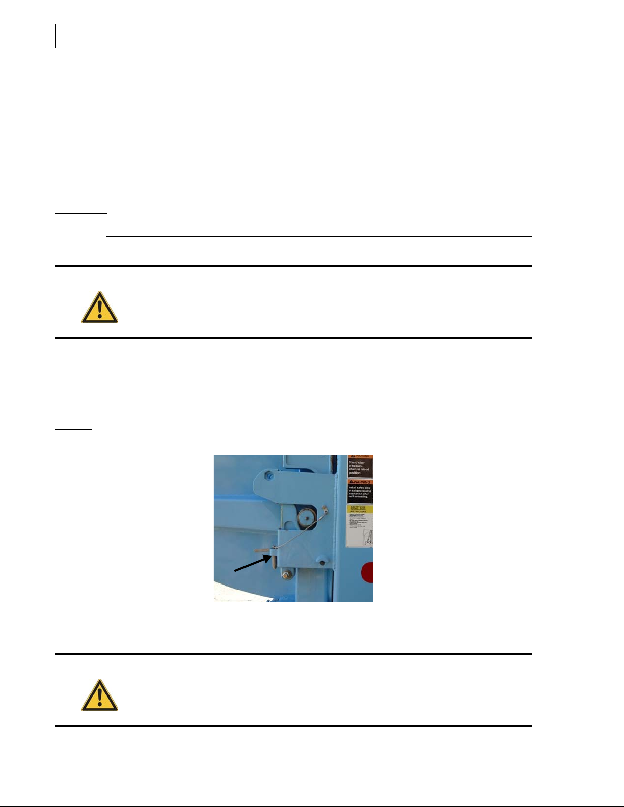
2. Remove the tailgate-locking mechanism safety pins.
Figure 2-4
The tailgate safety prop shall be set each time the tailgate is open for inspection or
maintenance purposes.
Safety pin
3. Start the engine.
4. Turn on the pump.
Danger!
Prior to raising the tailgate, make sure that no one is standing behind the vehicle and that
the body is empty.
Page 39
Safety 29
5. With the Tailgate Up Switch on the in-cab control panel, raise the tailgate about 3 feet (enough
to raise the safety prop).
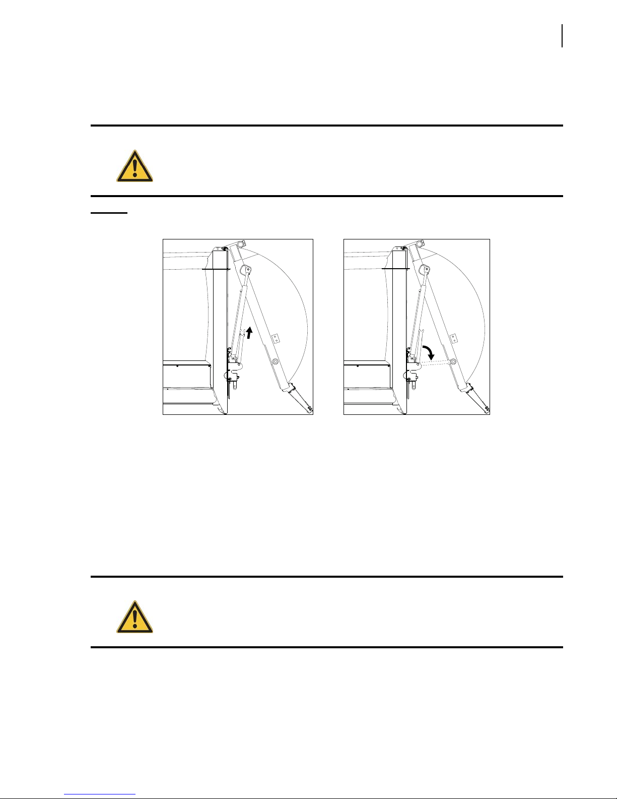
6. Pull the safety prop upward and set it down (see Figure 2-5).
Danger!
Figure 2-5
Stand clear of tailgate path while setting the safety prop.
Pulling the safety prop upward (left) and setting it down (right)
7. Lower the tailgate onto the safety prop using the Tailgate Down Switch on the in-cab control
panel.
Putting the Tailgate Safety Prop Back in Place
To put the tailgate safety prop back in its home position:
1. Start the engine.
2. Turn on the pump.
3. Raise the tailgate by about 3 feet.
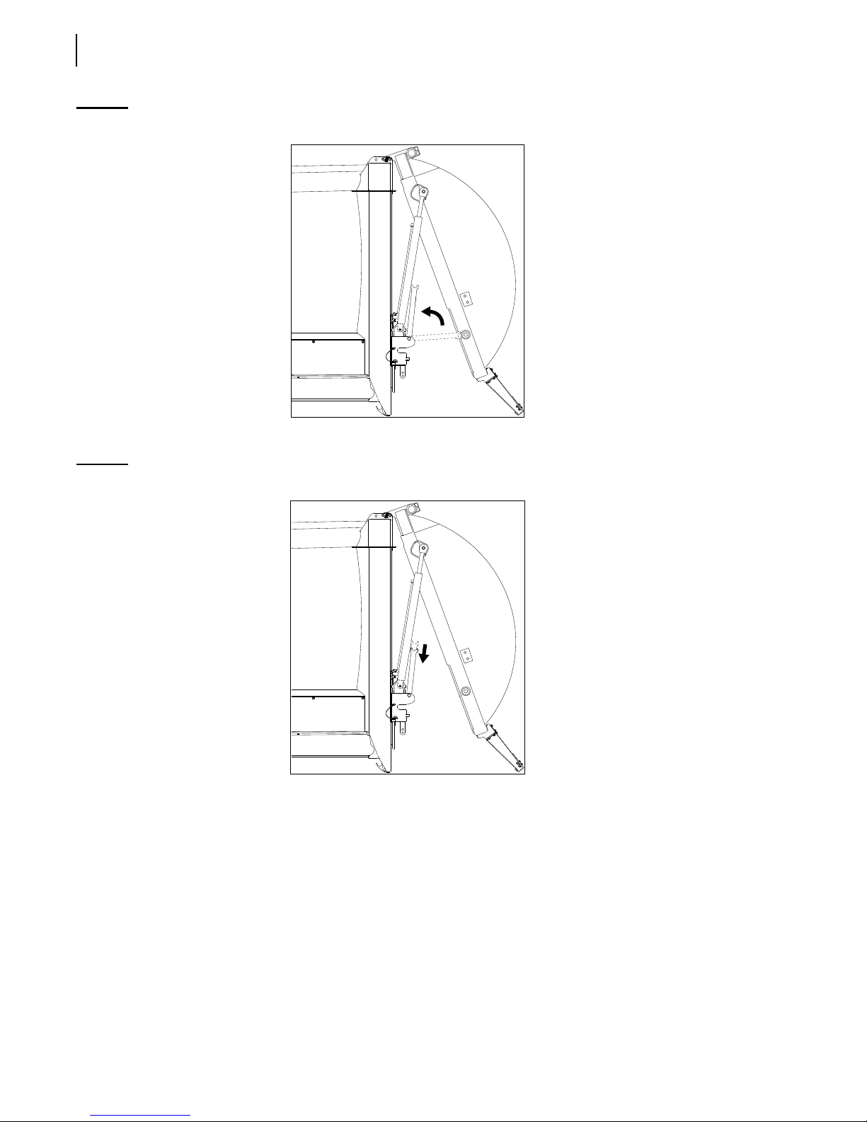
4. Raise the tailgate safety prop (see Figure 2-6).
Danger!
Stand clear of tailgate path while putting the safety prop back in its home position.
Page 40
30 Safety
Figure 2-6
5. Release your grip on the safety prop to set it in its home position.
Figure 2-7
Raising the tailgate safety prop
Setting the safety prop in its home position
6. With the Tailgate Down Switch on the in-cab control panel, completely close the tailgate.
TAILGATE OPEN light indicator should turn off.
The
7. Put the safety pins back in place.
Securing Tailgate Safety Pins
The tailgate safety pins ensure that the tailgate can not be opened accidentally. These pins must be in
place unless you are unloading refuse or servicing the tailgate. Remember these two critical points:
Before operating the W
side) [see Figure 2-8].
ITTKE PENDULUM™, secure tailgate with both safety pins (one on each
Page 41
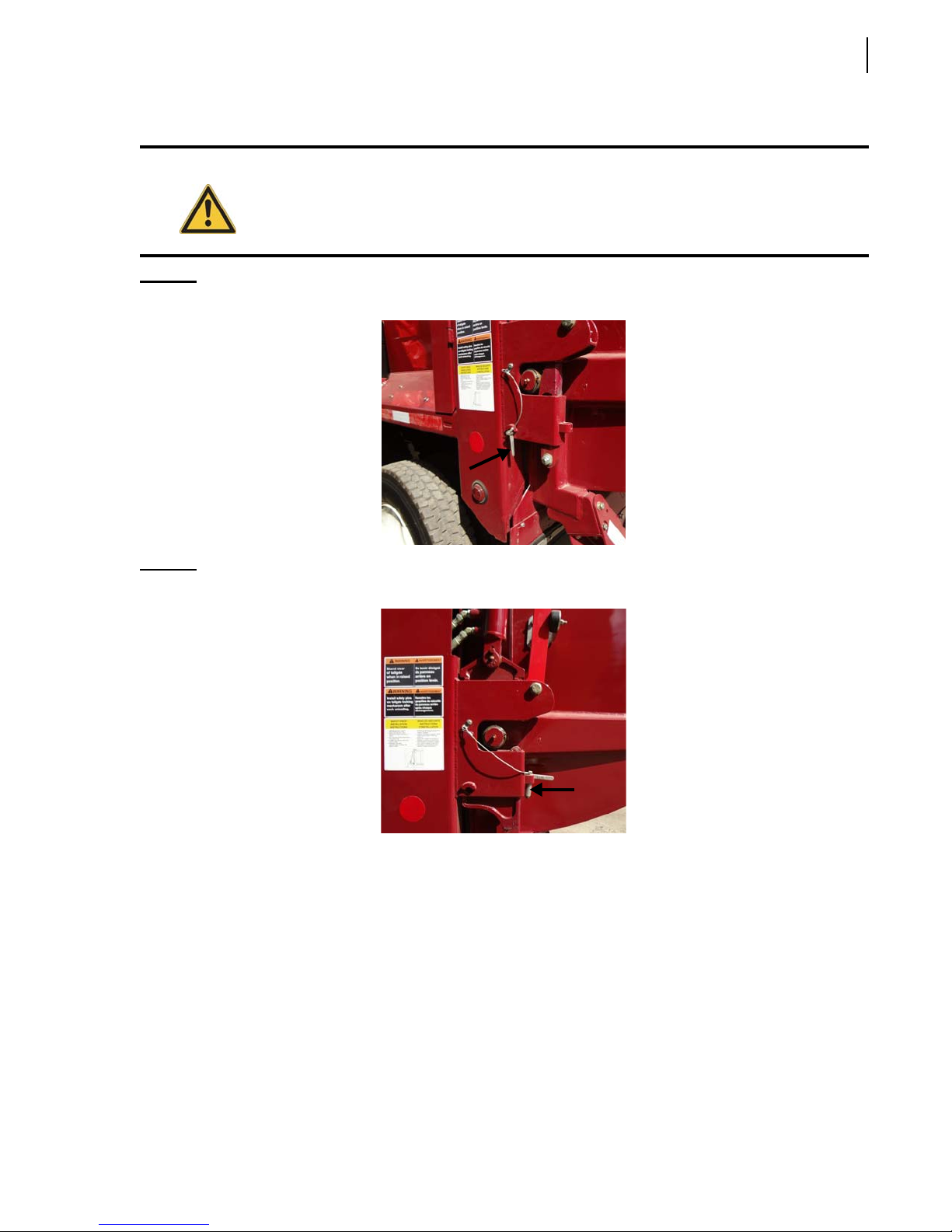
Before opening the tailgate, remove both tailgate safety pins (see Figure 2-9).
Safety 31
Warning!
Figure 2-8
Figure 2-9
Tailgate safety pin in locking position
Tailgate safety pin in storage position
Any vehicle with a tailgate not properly secured by a manual locking device (i.e. tailgate
safety pins) is considered unsafe.
Camera System (optional)
WITTKE PENDULUM™ units can be equipped with up to five (5) cameras.
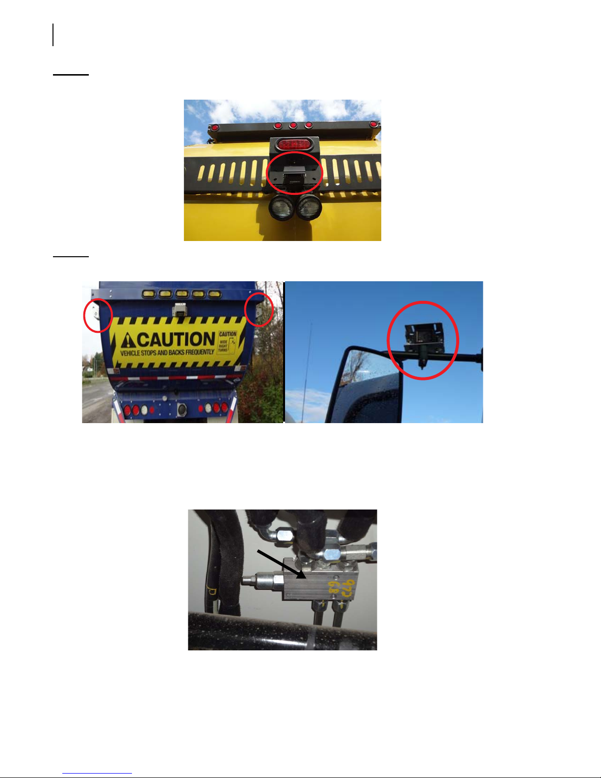
These cameras can be installed in the following locations: tailgate center 2/3 (see Figure 2-10), LH
side alley 2/3 (see Figure 2-11, left), RH side alley 2/3 (see Figure 2-11, left), LH side mirror
(see Figure 2-11, right), and RH side mirror (not shown).
The operator can switch from one camera to the other using a selector switch located on the 7” LCD
color monitor installed in the cab.
Refer to the camera manufacturer’s manual for more information.
Page 42
32 Safety
Figure 2-10
Figure 2-11
Camera on tailgate center
Cameras on both sides of tailgate (left) and on left-hand side mirror (right)
Tailgate Holding Valve
Located under the rear section of the body, this holding valve ensures that the tailgate will not open
during the packing cycle.
Page 43

Safety 33
Safety Lockout Tests
The safety lockout tests are part of your daily inspection. Successful completion of these tests ensures
that your unit is safe to operate. If any of these tests fail, do not operate your unit until the appropriate
adjustment or service has been completed.
IMPORTANT: Your front loader unit may be equipped with other safety lockout options not mentioned herein.
Consult your supervisor and/or maintenance department if you have questions or you are in doubt.
Hopper Door Proximity Switch
Successful completion of this test ensures that the front loader Hopper Door proximity switch is
working properly. If the hopper door is open, all hydraulic functions should become inoperative.
Warning!
Injury or death may occur if you attempt to enter the body while the pendulum packer or
arms are working.
For this test, proceed as follows:
1. Open the hopper door.
2. Ensure that the warning message “Pump: Hopper Door Not Closed” appears on the multiplex
display monitor (see Figure 3-2) and that both Pump button and Hopper Door Open indicator
light on the control panel are flashing red.
3. Verify that all hydraulic functions have been rendered inoperative by activating one of the control
buttons, such as the Tailgate Up button on the control panel.
4. If the hydraulic system is still operative, the Hopper Door proximity switch may need to be
adjusted or replaced. Refer to the Limit and Proximity Switches section in the Maintenance
Manual.
Arms Partly Raised Proximity Switch in Packing Mode
Successful completion of this test ensures that the arms will not raise above canopy if the pendulum
packer is not in its “home” position.
For this test, proceed as follows:
1. Fully lower the arms.
2. Press the Pack button on the control panel.
3. Stop the pendulum packer before it reaches its down position by pressing the Stop button.
4. Raise the arms.
They should stop above canopy.
5. If the arms do not stop above canopy, the Arms Partly Raised proximity switch (located on the
right side of the arm tube) may need to be adjusted or replaced. Refer to the Limit and Proximity
Switches section in the Maintenance Manual.
Page 44

34 Safety
IMPORTANT: The Arms Up function is disabled if the pendulum packer is not in its “home” position.
Arms and Forks Fully Retracted Proximity Switches
Successful completion of this test ensures that the Arms Not Stowed button on the control panel
(see Figure 3-16) turns red when the arms and forks are moved away from their parked position.
Caution!
Check for sufficient clearance above the vehicle before operating both the arms and forks.
For this test, proceed as follows:
1. Lower the arms and forks.
The Arms Not Stowed button on the control panel should become red.
2. Completely raise the arms without parking the forks.
The Arms Not Stowed button should still be red.
3. Park the forks.
The Arms Not Stowed button should no longer be red.
4. If the Arms Not Stowed button on the control panel is still red, the related proximity switches
(one located on the left-hand side fork, the other on the left side of the arm tube) may need to be
adjusted or replaced. Refer to the Limit and Proximity Switches section in the Maintenance
Manual.
Pendulum Packer In “Home” Position Proximity Switch
Successful completion of this test ensures that you will not accidentally dump debris into the hopper
while the pendulum packer is not in its “home” position (i.e. up position).
For this test, proceed as follows:
1. Lower the front loader arms fully.
2. Press the Pack button on the control panel to move the pendulum packer to mid-position.
3. Operate the Arms Up function on the joystick.
The arms should not rise further than the top of the cab.
4. If the arms rise past this point, the Pendulum Packer In “Home” Position or Arms Partly Raised
proximity switches may need to be adjusted or replaced. Refer to the Limit and Proximity Switches
section in the Maintenance Manual.
Top Door Fully Open Proximity Switch
Successful completion of this test ensures that you cannot accidentally dump refuse on top of the top
door.
Page 45
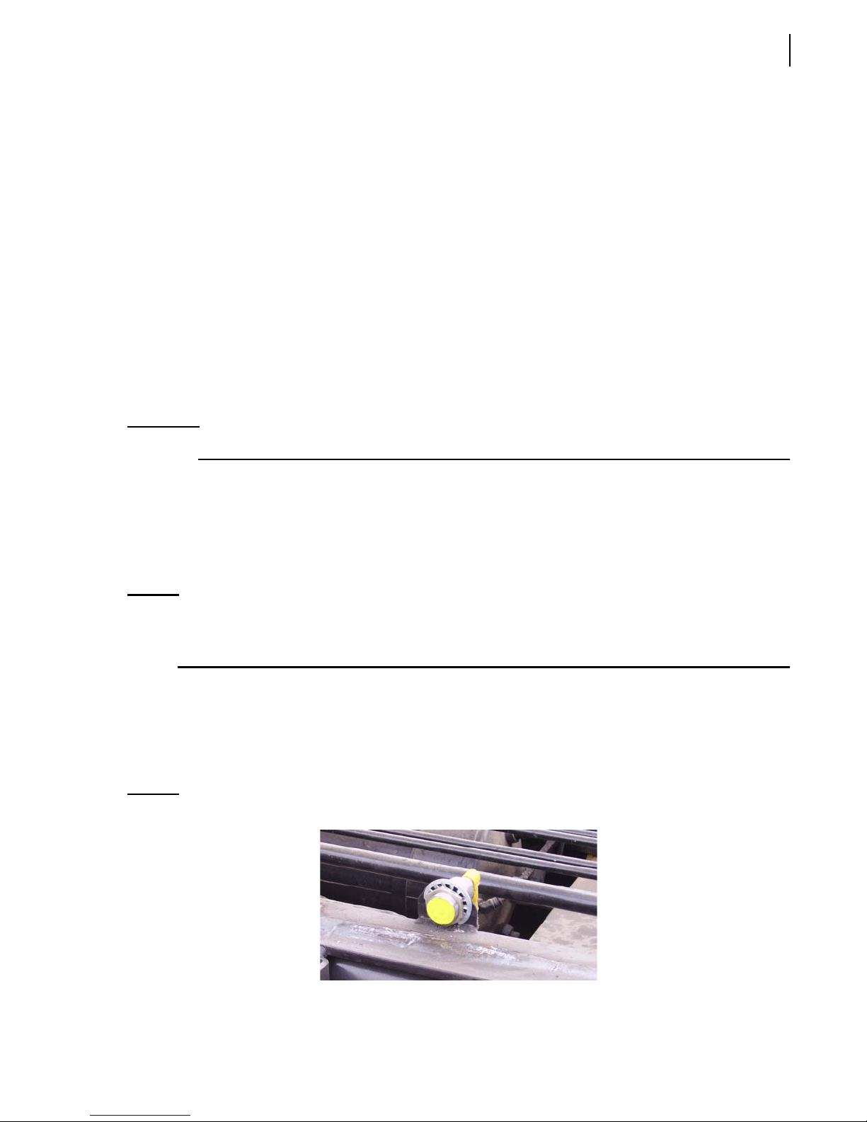
For this test, proceed as follows:
1. Open the top door until the Roof Open button (see Figure 3-17) on the control panel turns
green.
2. Using the Roof Close button (see Figure 3-17), partially close the top door until the Roof Open
button turns blue.
3. Activate the Arms Up function on the joystick.
The Arms Up function should not operate above cab windshield.
4. If the Arms Up function still operates above cab windshield, the Top Door Fully Open proximity
switch may need to be adjusted or replaced. Refer to the Limit and Proximity Switches section in
the Maintenance Manual.
Body Raised Proximity Switch
Performing this test ensures you know when the body is properly seated on the chassis. The body
should always be seated unless unloading or servicing is being performed.
IMPORTANT: Never drive the unit while the body is raised unless unloading.
Safety 35
To perform this test:
1. Lower the body using the Body Down switch on the in-cab control panel. Exit the cab and
visually confirm that the body is firmly seated on the chassis.
2. Remove tailgate safety pins, and open the tailgate by using the Tailgate Up button on the in-cab
control panel.
NOTE: When using in-cab controls, the body will not rise unless the tailgate is OPEN. As soon as the
body reaches a certain height, a buzzer will sound and a warning message will appear on the
multiplex display screen.
3. Raise the body using the Body Up switch on the control panel. A Body Raised message should
appear on the multiplex display screen.
4. If the Body Raised message DOES NOT appear on the screen, notify your maintenance
supervisor immediately. The Body Raised proximity switch may be inoperative (see Figure
2-12).
Figure 2-12
Body Raised proximity switch
Page 46
36 Safety
Quick Reference Lockout Chart
Hopper door open Pump circuit cut out - all controls
inoperative
Pendulum packer not in “home”
position
Top door closed or not fully
open
Arms Up function will not operate
above cab windshield
Arms Up function will not operate
above cab windshield
Cleanliness
Clean all the lights and safety decals so you and the surrounding pedestrians and drivers will be aware
of the truck at all times.
Locking Out and Tagging Out the Vehicle
For any inspection, repair or general maintenance being done on the vehicle, whether on the road or
at the shop, it is the employer’s responsibility to establish and see to the application of a proper
lockout and tagout procedure.
To lock out and tag out a W
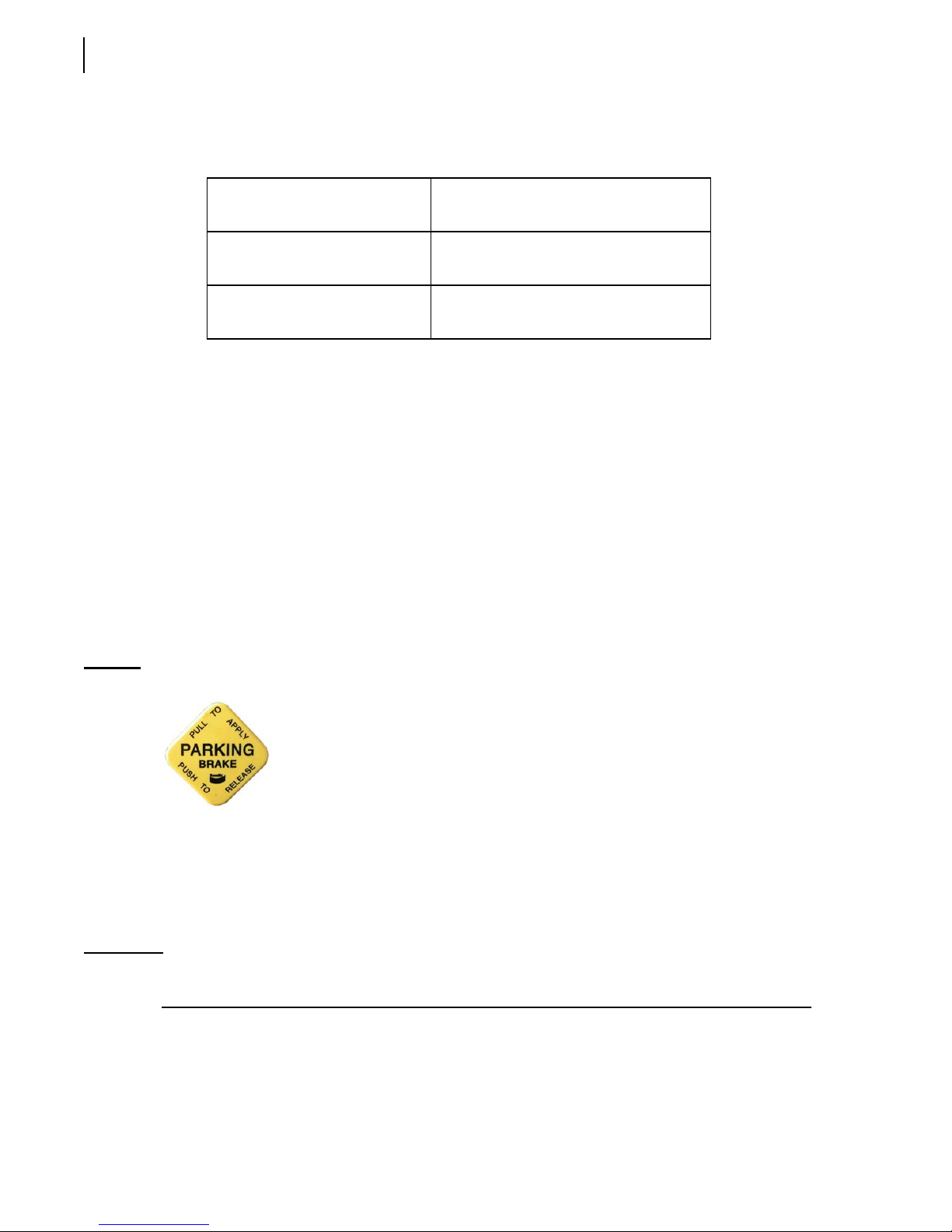
1. Park the vehicle on safe, level ground, and apply the parking brake (see Figure 2-13).
Figure 2-13
Parking brake sign
ITTKE PENDULUM™ vehicle:
2. Make sure that the body is completely unloaded.
3. Switch off the hydraulic pump.
4. Turn off the engine, remove the key from the ignition, store it in a safe and controlled area
(preferably on yourself), and tape over the ignition switch.
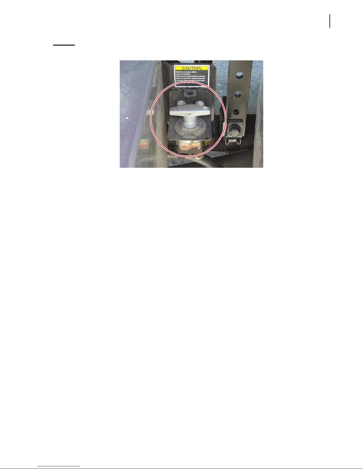
5. Turn off and lock the master switch.
IMPORTANT: The battery set of the WITTKE PENDULUM™ is equipped with a master switch (see Figure 2-14) that
must be turned off.
Page 47
Safety 37
Figure 2-14
6. Chock all wheels.
7. Put an “OFF SERVICE” tag on the driver’s wheel and on the front windshield.
8. Use safety props to block any system that could move by gravity (open tailgate, raised body, etc.).
9. Drain all air tanks.
10. Verify and inspect any security device and/or mechanism to make sure that there is no bypass
Master switch
and that they are all functional.
Shutting Down the Vehicle
If the vehicle has to be stored for an extended period of time, follow the chassis manufacturer’s
shutdown and maintenance requirements.
Also:
1. Park the vehicle on a hard level surface, and apply the parking brake (see Figure 2-13).
2. Make sure that all moving parts are in their home position (tailgate, arms, packer, etc.).
3. Turn off, in sequence, the hydraulic pump (see Figure 2-17), the electrical system, the engine and
the master switch (see Figure 2-14).
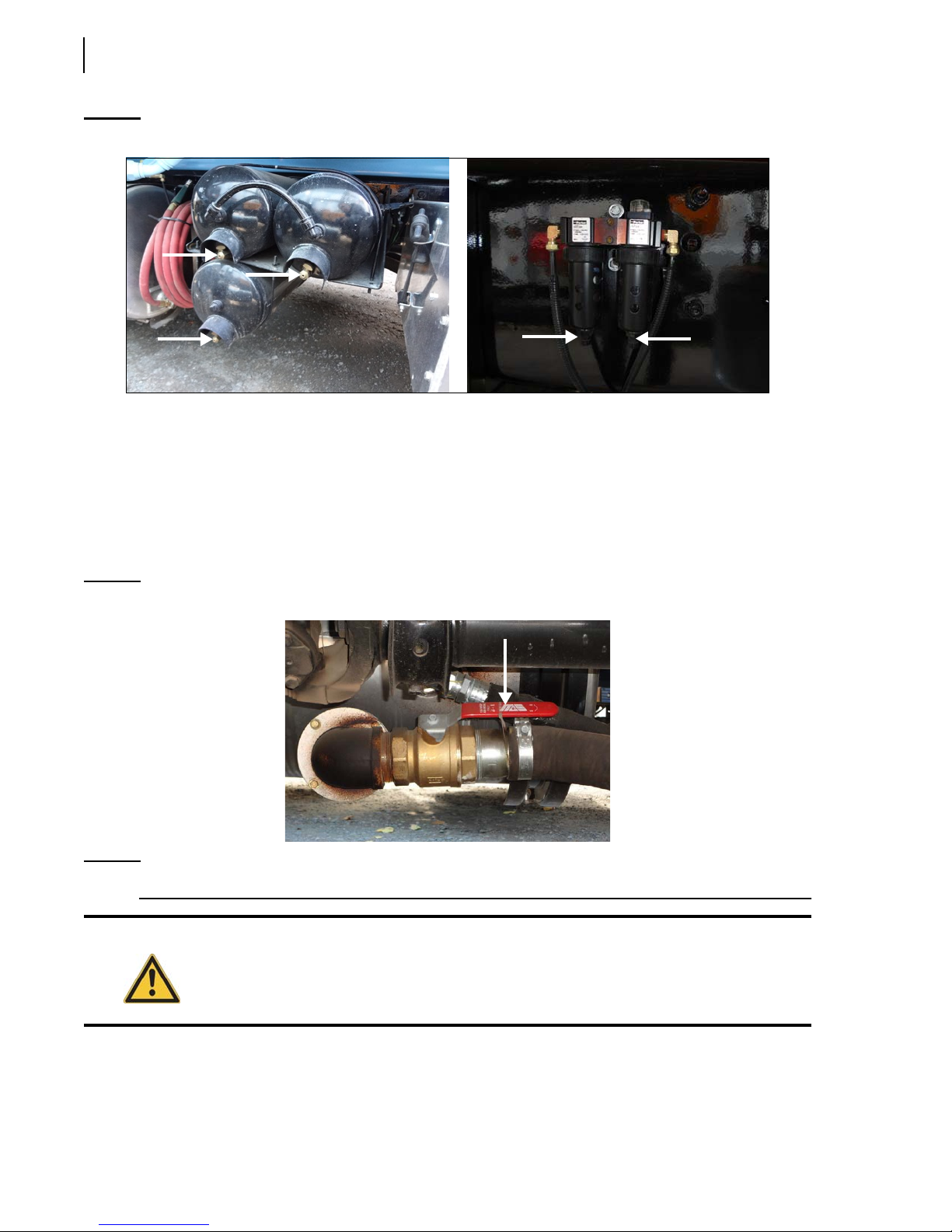
4. Drain all air tanks and water trap.
Page 48
38 Safety
Figure 2-15
Drain valves on air tanks (left) and water trap (right)
Prior to Start Up
Before starting the vehicle:
1. Make sure no system will engage and/or start to operate as you start the engine.
2. Make sure the shut-off valve on the hydraulic tank is fully open before starting the vehicle
(see Figure 2-16).
Figure 2-16
NOTE: The hydraulic tank model may vary according to the options installed on the vehicle.
Warning!
Suction line shut-off valve
Failure to fully open the main valve will cause immediate damage to the pump, even if
the pump is turned off.
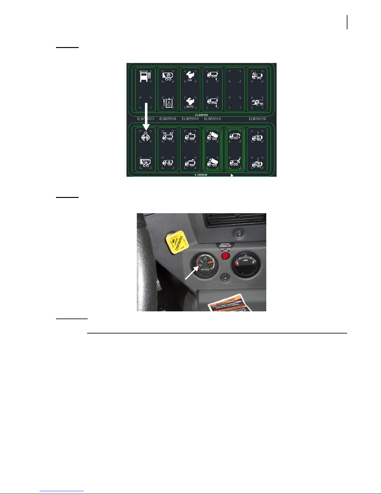
3. Engage the hydraulic system by pressing the Pump button on the control panel (see Figure
2-17).
Page 49
Safety 39
Figure 2-17
Figure 2-18
Hydraulic pump ON/OFF button
Once the engine is started, wait for air pressure to build up to at least 70 psi.
Air pressure indicator
IMPORTANT: Do not operate or move the vehicle until air pressure has reached 70 psi.
Page 50

40 Safety
Page 51
3
Controls and
Indicators
The WITTKE PENDULUM™ has a series of controls and
indicators that allow easier operation of the different
functions that come with the vehicle. These controls
and indicators are mainly located on the in-cab control
panel and on the dashboard.
Labrie’s Multiplexed System
Labrie has equipped your WITTKE PENDULUM™ unit
with a CAN bus-based multiplexed system, which
integrates a display monitor, a control panel, a joystick,
and a set of electronic modules. This whole system has
been designed to help you operate your unit in an
efficient and easy way. Labrie’s multiplexed system is
reliable and safe, and it requires less wiring harnesses
to operate. It can also monitor various function status
of the body and display warning and caution messages.
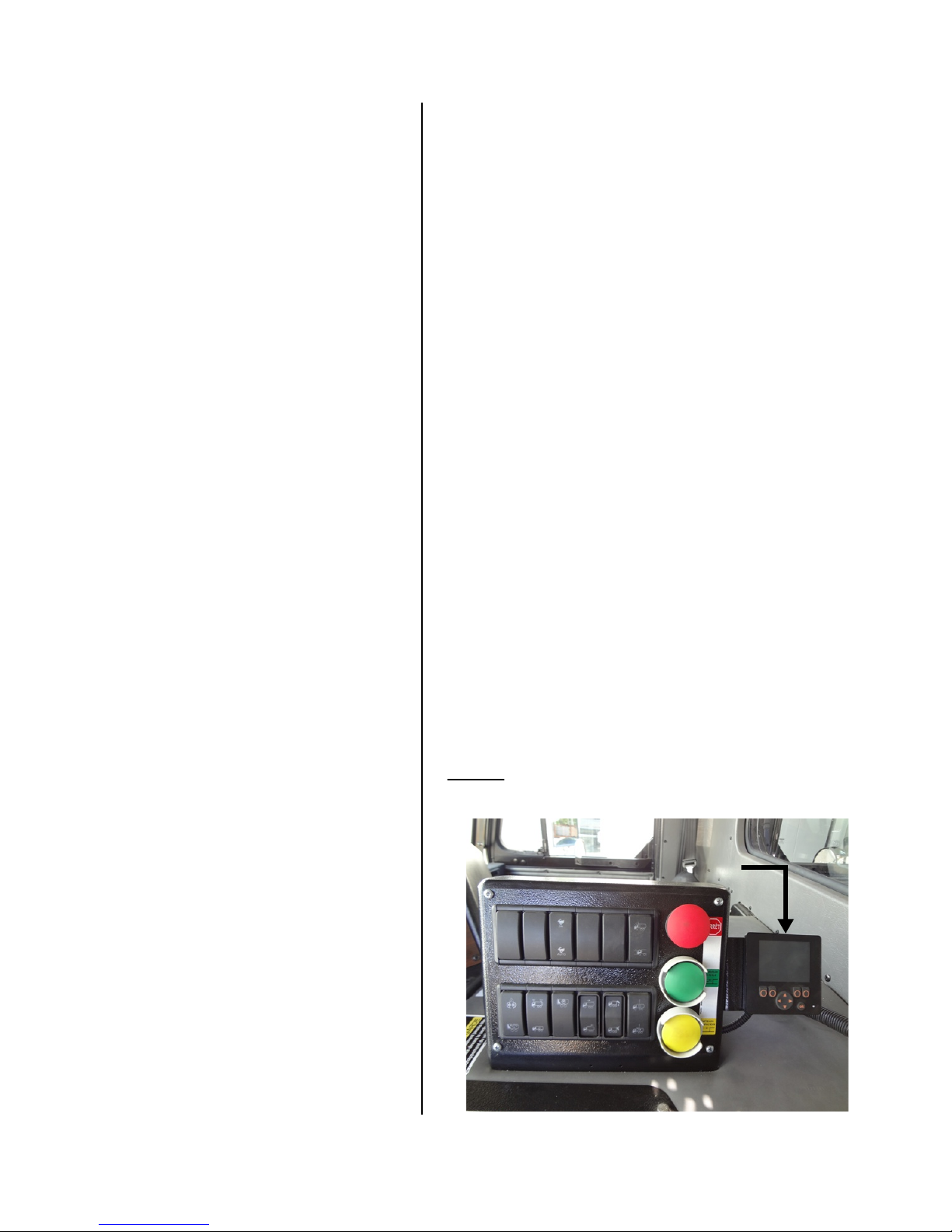
Through its display monitor (see Figure 3-1), Labrie’s
multiplexed system informs you of any malfunction
that may occur during use of the truck. Various caution
and warning messages can be displayed on the
monitor, depending on the seriousness of the
situation. Messages in yellow blocks indicate that
caution should be used; messages in red blocks
indicate a warning situation that must be dealt with
quickly.
Figure 3-1
Display monitor
Page 52
42 Controls and Indicators
Each time the operator turns the ignition key on, a complete bit test of the multiplexed system is
conducted. This test takes about 5 seconds to complete.
NOTE: A flashing green light on the monitor indicates that the display power is on. This light should
be blinking steadily at 2 Hz during normal operation. If it blinks at a faster rate, it is a sign of a
problem with the monitor. A flashing red light on the monitor is also a sign of a problem. Call
LabriePlus for support.
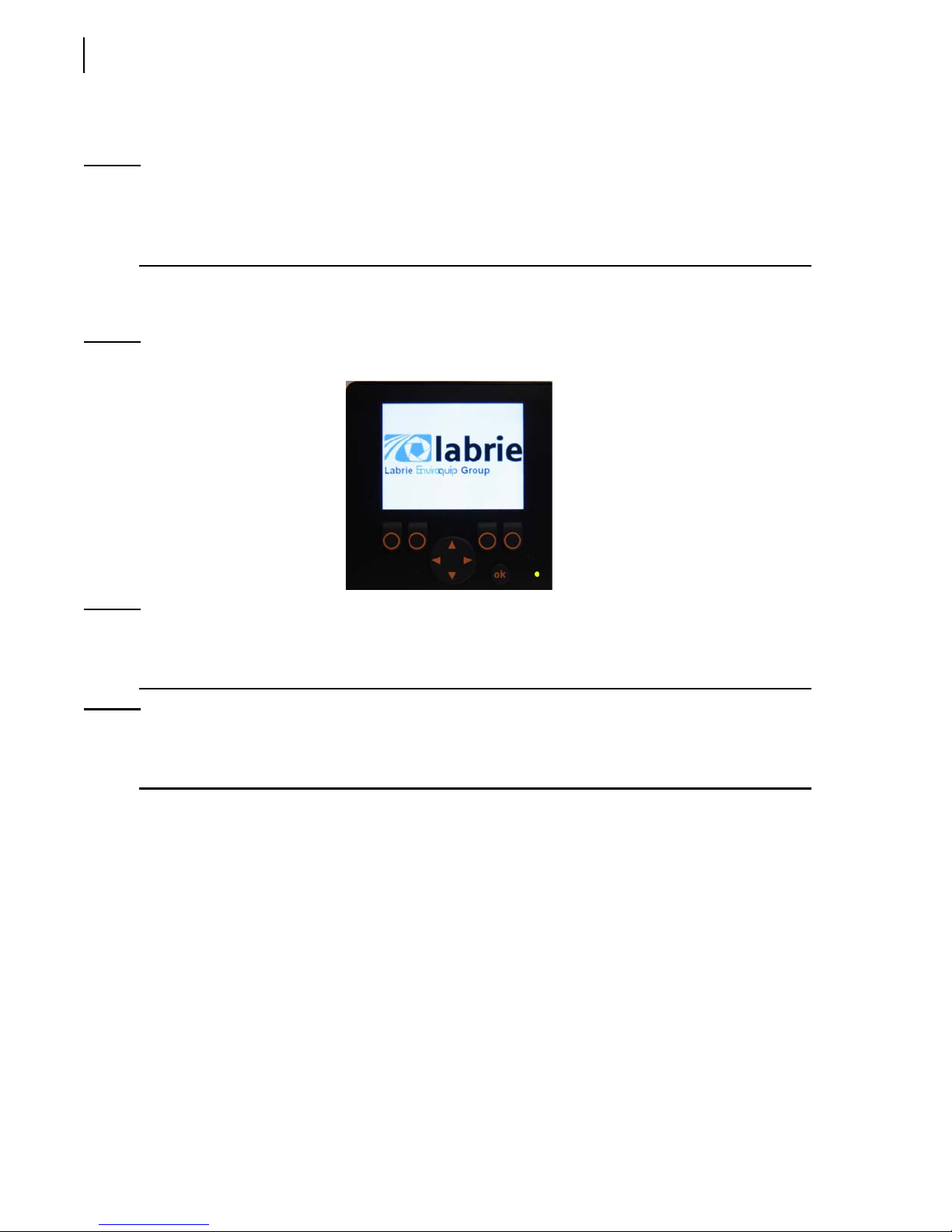
The logo of Labrie Enviroquip Group appears momentarily on the display monitor at the start of the
system (see Figure 3-2).
Figure 3-2
NOTE: If the Welcome Screen with the Labrie logo stays on continuously, there may be a
Labrie logo on the display monitor
communication problem between the monitor and the master control module. Report this
problem to the maintenance personnel.
NOTE: The display monitor works even if the engine is not started. All it needs is electrical power.
However, if you start the engine, the monitor will reboot to reflect the changes caused by the
starting of the truck.
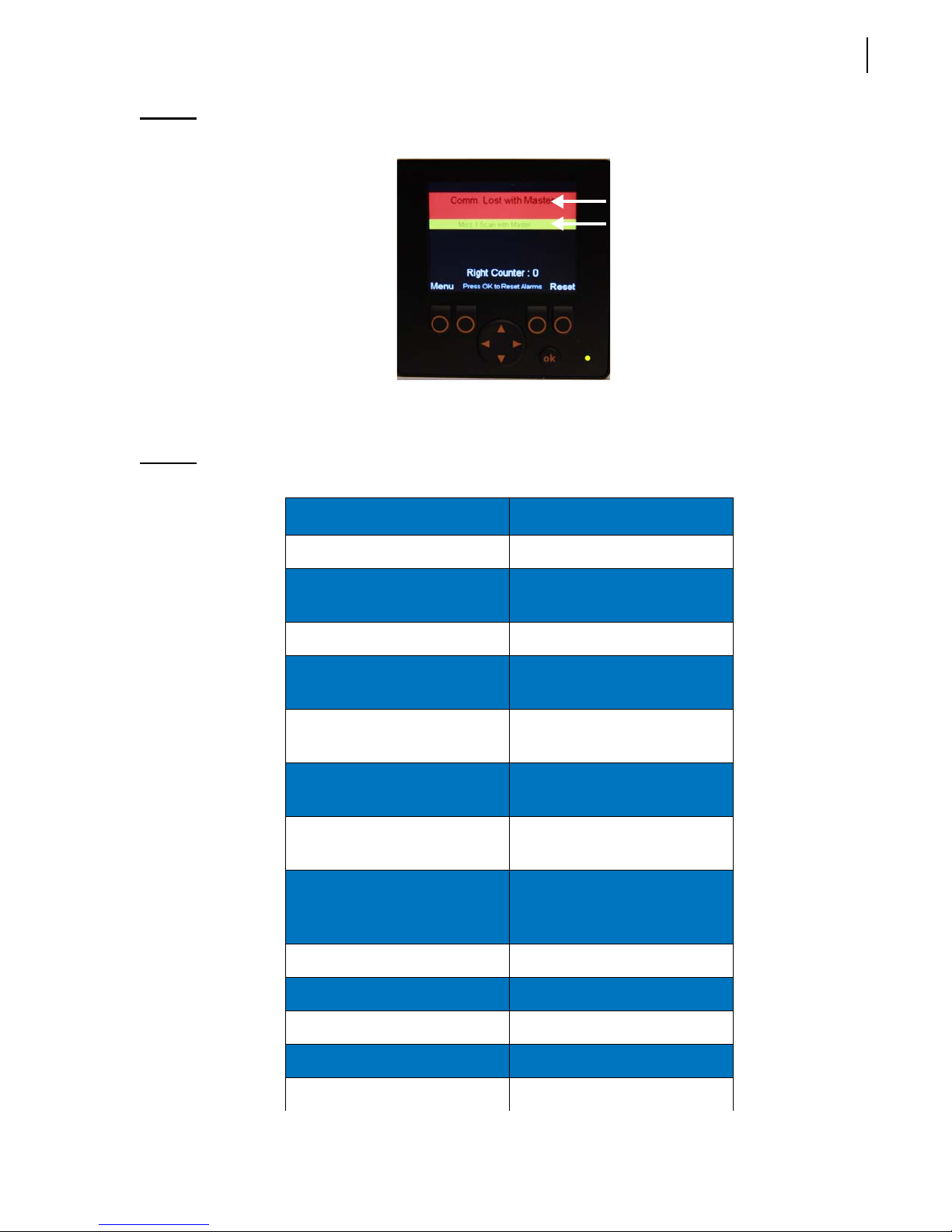
Warning and Caution Messages
On the display monitor, messages in yellow blocks indicate that caution should be used and messages
in red blocks indicate a warning situation that must be dealt with quickly.
Page 53
Controls and Indicators 43
Figure 3-3
Warning and caution messages on monitor
See Table 1 for a list of warning and caution messages. Please note that this list is not exhaustive.
Table 1 Warning messages (cont’d)
Warning and Caution Messages Solution
ArmRaise:AirWeigh Signal Unload Body
ArmRaise:Packer Not
Retract Packer
Retracted
ArmRaise:Roof Not Opened Open Roof (Top Door)
Auto-Dump: Wrong Driver
Position
Auto-Dump:Arm Too High to
Change Driver Position Switch
to Correct Position
Lower Arms
Start
Auto-Dump:Max Angle
Reached
Auto-Dump:Pump Not
Operate Arms and Forks
Manually
Engage Pump
Running
Bar Stop Reached First Push Bar Stop Override
Switch, then Move Container
out of Bar Stop
Body: Pump Not Started Engage Pump
Buzzer:Body Raised Lower Body
Buzzer:TailGate Unlocked Lock Tailgate
Control is External Disable External Control
ESTOP:Aux Emergency Stop Pull Up Aux EStop Button
Page 54

44 Controls and Indicators
Table 1 Warning messages (cont’d)
Warning and Caution Messages Solution
ESTOP:Cab Emergency Stop Pull Up Cab EStop Button
ESTOP:Ext Emergency Stop Pull Up Ext EStop Button
Fork:Arm Above MidHeight Lower Arms Below MidHeight
Fork:Pump Not Started Engage Pump
High Hydraulic Oil Temp Turn Off Engine and Refer to
J1939:Network NOT OK Call LabriePlus
Low Hydraulic Oil Add Hydraulic Oil
Miss 1 Scan with Master Refer to Maintenance
Maintenance Personnel
Personnel or LabriePlus
Packer:Arm Above MidHeight Lower Arms Below MidHeight
Packer:Extended Prox Timeout Check Full Extended Proximity
Switch
Packer:Pump Not Started Engage Pump
Packer:Retracted Prox Timeout Check Full Retracted Proximity
Switch
Packer:Roof Not Opened Open Roof (Top Door)
Pump Stop:Main Air Pressure Let the Air Build Up to
Required Pressure
Pump:Auto-Dump Button ON Call LabriePlus (Button Must
be OFF to Engage Pump)
Pump:Aux EStop Pull Up Aux EStop Button
Pump:Cab EStop Pull Up Cab EStop Button
Pump:Deadman Switch ON Call LabriePlus (Switch Must
be OFF to Engage Pump)
Pump:Ext EStop Pull Up Ext EStop Button
Pump:Fork Width Decr. Switch ONCall LabriePlus (Switch Must
Pump:Fork Width Incr. Switch ONCall LabriePlus (Switch Must
be OFF to Engage Pump)
be OFF to Engage Pump)
Page 55

Table 1 Warning messages (cont’d)
Warning and Caution Messages Solution
Controls and Indicators 45
Pump:Hopper Door Not
Close Hopper Door
Closed
Pump:Main Air Pressure Let the Air Build Up to
Required Pressure
Pump:Packer Extend Switch ONCall LabriePlus (Switch Must
be OFF to Engage Pump)
Pump:Packer Retract Switch ONCall LabriePlus (Switch Must
be OFF to Engage Pump)
Pump:PTO Not OK Refer to Maintenance
Personnel or LabriePlus
Pump:Roof Open Switch ON Call LabriePlus (Switch Must
be OFF to Engage Pump)
Pump:RoofCloseSwitchON Call LabriePlus (Switch Must
be OFF to Engage Pump)
Pump:RPM too High Engine Must Be at Idle Speed to
Engage Pump
Pump:SpeedUpAuto Switch ONCall LabriePlus (Switch Must
be OFF to Engage Pump)
Pump:SpeedUpON Switch ON Call LabriePlus (Switch Must
be OFF to Engage Pump)
Pump:TagAxle Down Switch ONCall LabriePlus (Switch Must
be OFF to Engage Pump)
Pump:TagAxle Up Switch ON Call LabriePlus (Switch Must
be OFF to Engage Pump)
Pump:TailGate Down Switch ONCall LabriePlus (Switch Must
be OFF to Engage Pump)
Pump:TailGate Up Switch ON Call LabriePlus (Switch Must
be OFF to Engage Pump)
Pump:Trans. Not OK Refer to Maintenance
Personnel or LabriePlus
Raise Body:Truck Moving Speed Should Be Below 6 mph
(10 km/h)
Raise Body:Arm Not Parked Park Arms
Raise Body:Tag Not Down Lower Tag Axle
Page 56

46 Controls and Indicators
Table 1 Warning messages (cont’d)
Warning and Caution Messages Solution
Raise Body:Air Susp. Not
Down
Raise Body:TG Not Open or
Close
Roof:Pump NOT Started Engage Pump
Service Oil Filter #1 Replace Oil Filter #1
Service Oil Filter #2 Replace Oil Filter #2
Tailgate Open: Body Raised Lower Body
TailGate:Pump NOT Started Engage Pump
Wrong Driver Position Move Driver Position Switch to
Table 2 Error messages (cont’d)
Error Messages Solution
Lower Air Suspension
Fully Open or Fully Close
Tailgate
Opposite Position
Button Pack 12 is disconnected Refer to Maintenance
Personnel or LabriePlus
Button Pack 13 is disconnected Refer to Maintenance
Personnel or LabriePlus
Button Pack 14 is disconnected Refer to Maintenance
Personnel or LabriePlus
Button Pack 15 is disconnected Refer to Maintenance
Personnel or LabriePlus
CAN Error Level 1 Refer to LabriePlus
CAN Error Level 2 Refer to LabriePlus
CAN Error Level 3 Refer to LabriePlus
Comm. Lost with Master Refer to Maintenance
Personnel or LabriePlus
Module 11 is disconnected Refer to Maintenance
Personnel or LabriePlus
Module 11 not Connected Refer to Maintenance
Personnel or LabriePlus
Page 57

Table 2 Error messages (cont’d)
Error Messages Solution
Module 25 is disconnected Refer to Maintenance
Module 25 not Connected Refer to Maintenance
Module 30 is disconnected Refer to Maintenance
Module 30 not Connected Refer to Maintenance
Module 50 is disconnected Refer to Maintenance
Module 50 not Connected Refer to Maintenance
Controls and Indicators 47
Personnel or LabriePlus
Personnel or LabriePlus
Personnel or LabriePlus
Personnel or LabriePlus
Personnel or LabriePlus
Personnel or LabriePlus
Module 60 is disconnected Refer to Maintenance
Personnel or LabriePlus
Module 60 not Connected Refer to Maintenance
Personnel or LabriePlus
Should the system issue a warning or a caution message, it will appear on the Main page.
For example, if “Pump Not Started: Main Air Pressure” appears on the Main page of the display
monitor, the solution would be to wait until the required main air pressure level is reached.
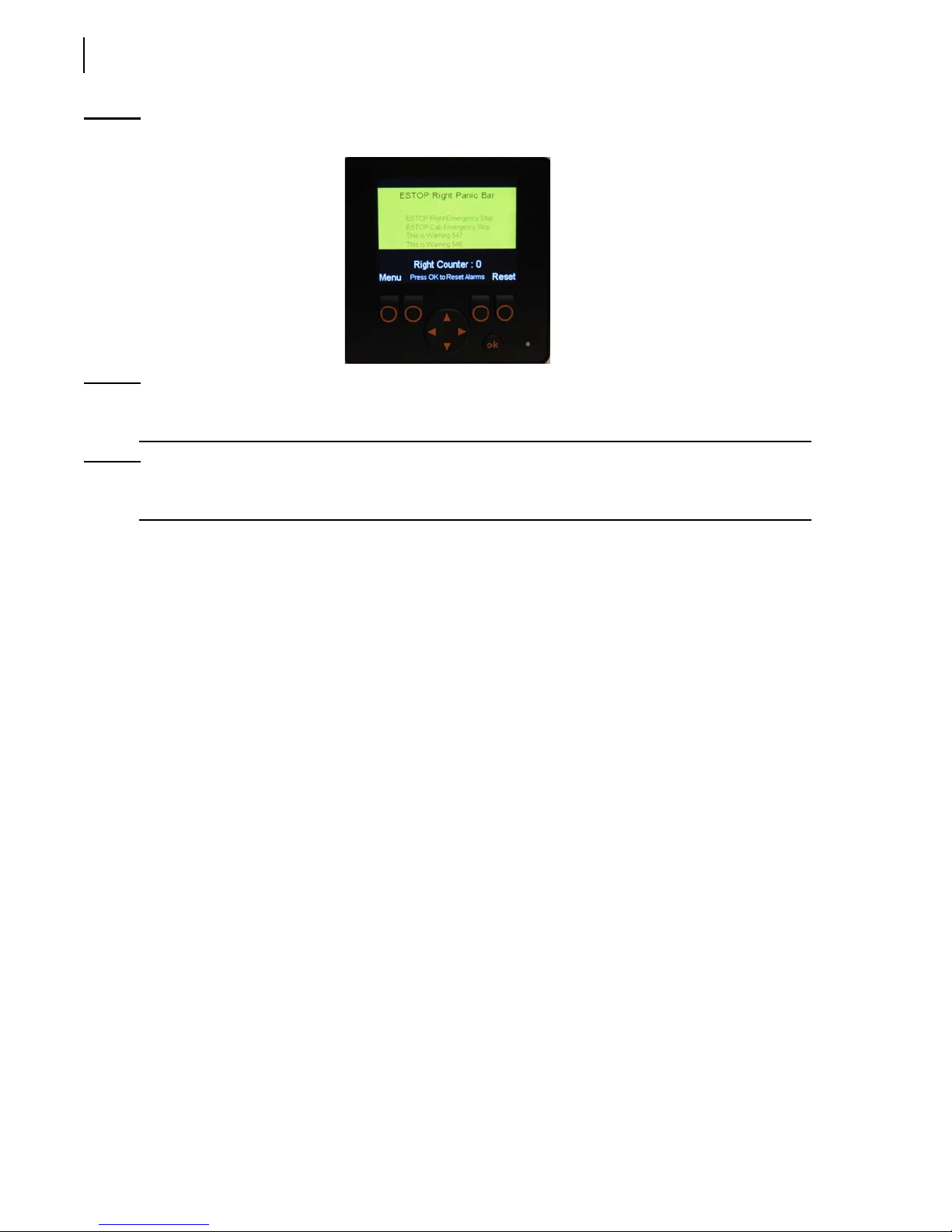
For a specific problem or condition that requires special attention, the multiplexed system will
suggest a possible cause to the operator. This will appear in bold and large print on the monitor
screen (active cause). The operator should check if the problem stems from the highlighted or active
cause. One possible cause is highlighted at a time. What is shown in light and small print in the lower
part of the screen are causes that have already been dealt with (see Figure 3-4).
Page 58
48 Controls and Indicators
Figure 3-4
NOTE: If the system detects a problem, a beep will sound and a message will appear on the display
NOTE: To go back to the Main page or the Main Menu, press “Esc” as many times as necessary until
Example of a possible cause
monitor.
the desired page is displayed.
Hydraulic Oil Temperature Indicator (optional)
This optional indicator, when provided, shows you the current hydraulic oil temperature. This
indicator is found on the upper right-hand side corner of the screen.
Time and Date Indicator
A time and date indicator may be found on the upper left-hand side corner of the screen. The
availability of this indicator is based on the chassis on which the body is mounted. If the chassis
provides real-time clock information through the J1939 bus, time and date will appear on the screen.
To set the Time and Date indicator, go to the Main Menu and choose Time Adjust.
Main Menu
To access the Main Menu, press the far left button when the Main page is displayed.
When the Main Menu is displayed, you can have access to the following sections:
Multicycle
I/O Status
Program Version
Pump Usage (optional)
Auto-Dump (optional)
Time Adjust (available according to chassis)
Page 59
Controls and Indicators 49
Displayed in the lower center of the screen is an indicator that monitors traffic on the network. This
indicator is called Network Load, and it shows values that reflect such traffic.
NOTE: The higher the network load value is, the heavier the traffic is on the network.
To exit this page and return to the Main page, press “Esc”. To choose a section from the Main Menu,
highlight the desired section using the up/down arrows and press the “OK” button.
Multicycle
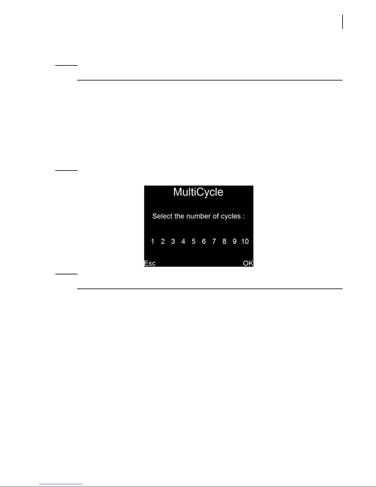
Labrie’s multiplexed system makes changing multicycle settings real easy! All you need is the display
monitor. Say you want to change the multicycle settings of the pendulum packer. Just select the
M
ULTICYCLE Page from the MAIN MENU by pressing the corresponding button at the bottom left
corner of the display monitor. Use the left and right arrows to select the desired number of packer
cycles and press “OK” to validate or Esc to cancel. The multicycle settings can be changed from one
to ten cycles.
Figure 3-5
M
ULTICYCLE
page
NOTE: The packer multicycle function has been preset at the factory to carry out five (5) cycles.
When the green button on the packer control station (see Figure 3-6) is activated, the packer will
move according to the default number of cycles (that is 5) or to the number of cycles you chose (up
to 10 cycles).
Page 60

50 Controls and Indicators
Figure 3-6
To test the new multicycle settings:
1. Press the green START CYCLE button.
2. Once the packer has completed its cycles and comes to a stop, switch off the hydraulic pump and
The number of cycles needs to be adjusted depending on the type of collection route used by the
vehicle. For example, if the pickups are numerous and close one to another, it may be required to
increase the number of cycles. This will allow the hopper to be clear for the next pickup.
Green S
TART CYCLE
turn off the engine.
button
Each time the packer completes a full cycle, the packer in “home” position proximity switch sends a
signal to the electronic module. The module then counts the amount of cycles that the packer does,
and will stop the packer after the preset amount of cycles has been reached.
I/O Status
In this section, you will find helpful information for troubleshooting body-related problems that you
may face in your day-to-day tasks. These problems can be of any kind: hydraulic, mechanical,
electrical or pneumatic.
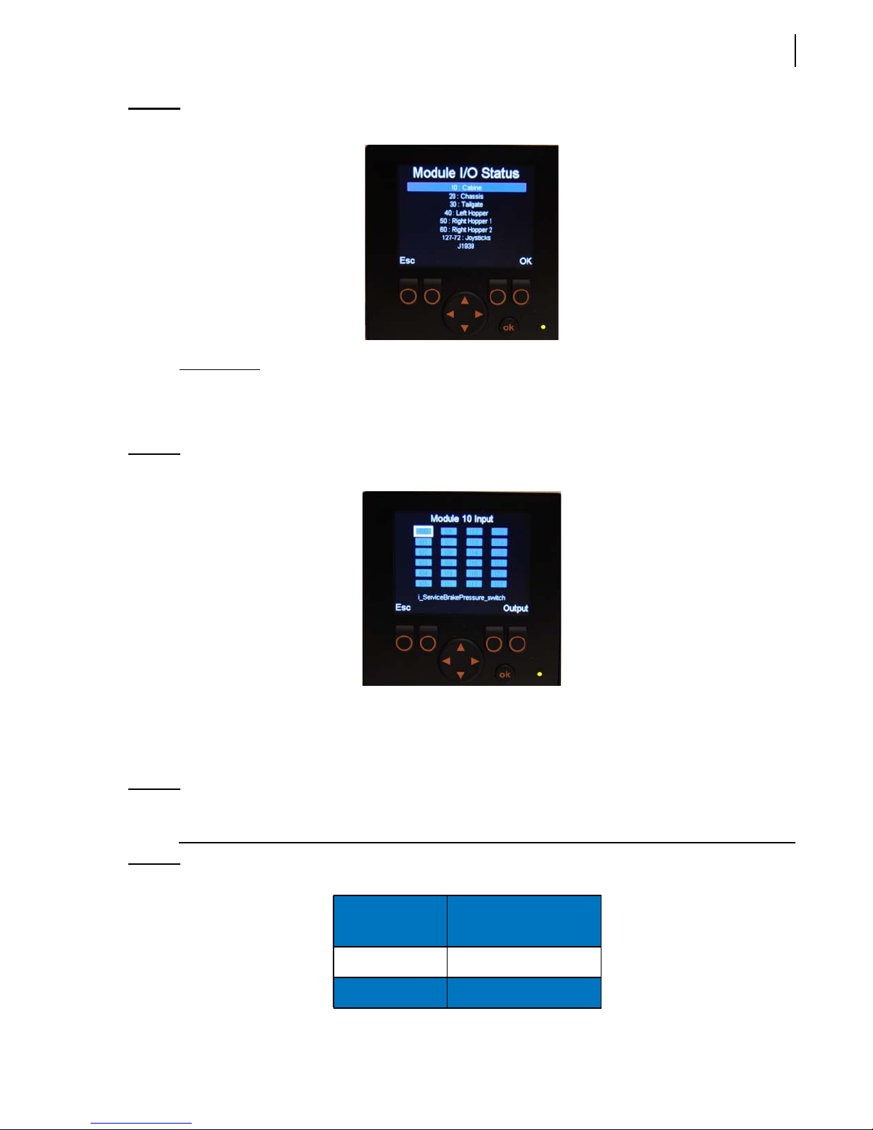
Select the control module corresponding to the part of the truck that needs to be checked.
For example, if you want to check all functions that are found in the cab, choose module #10. For all
functions that pertain to the chassis, choose module #20, etc.
To choose a particular module, use the up/down arrows to select it and enter “OK”.
NOTE: Entering “OK” can be done two ways: press either the far right button or the “OK” button.
Press “Esc” to return to the preceding page.
Page 61
Controls and Indicators 51
Figure 3-7
Input Status
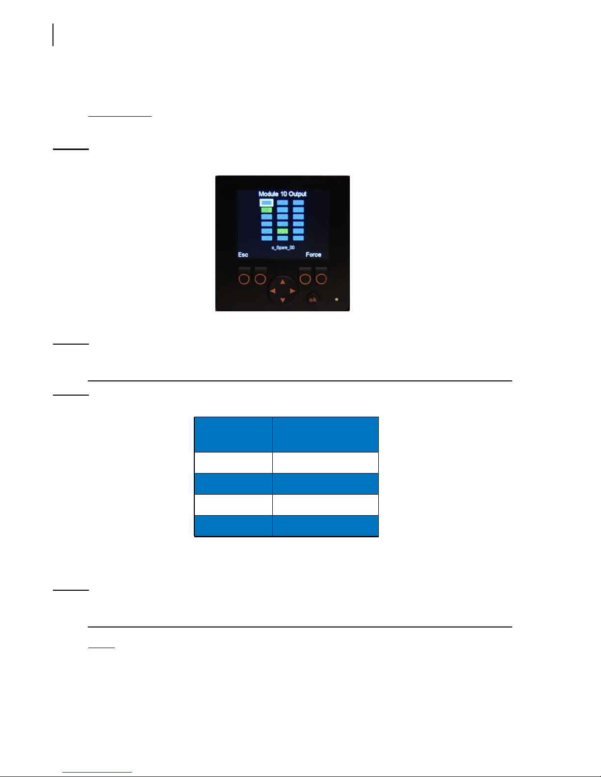
The Input Status page is accessible from the Module I/O Status page. After selecting the desired
module and pressing “OK”, the Input Status page of the selected module is displayed (see Figure
3-8).
Figure 3-8
Module I/O Status page
Input Status page
The Input Status page contains a set of rectangles. Each of these rectangles represents input elements,
which correspond to a particular function of the truck. For example, if you select rectangle I00, a short
description appears in the lower part of the screen, which indicates that this rectangle relates to the
input element coming from the service brake pressure switch.
NOTE: Each rectangle is numbered and relates to a specified function of the truck. However, for a
given number, the related function may vary from truck to truck.
Table 3 Colored rectangles
Rectangles
(inputs)
Blue Inactive
Green Active
Function Status
Page 62
52 Controls and Indicators
Press “Esc” to return to the preceding page.
Press the “Output” button to display the Output Status page.
Output Status
The Output Status page is accessible from the Input Status page (see Figure 3-9).
Figure 3-9
Output Status page
The rectangles found in this page are used to check the status of different outputs.
NOTE: Each rectangle is numbered and relates to a specified function of the truck. However, for a
given number, the related function may vary from truck to truck.
Table 4 Colored rectangles
Rectangles
(outputs)
Function Status
Blue Inactive
Green Active
Red Closed short-circuit
Yellow Open circuit
Press “Esc” to return to the preceding page.
Press the “Force” button to display the Force page.
NOTE: To go back to the Main page or the Main Menu, press “Esc” as many times as necessary until
the desired page is displayed.
Force
The Force page is accessible from the Output Status page. Just press the corresponding button to
access the Force page.
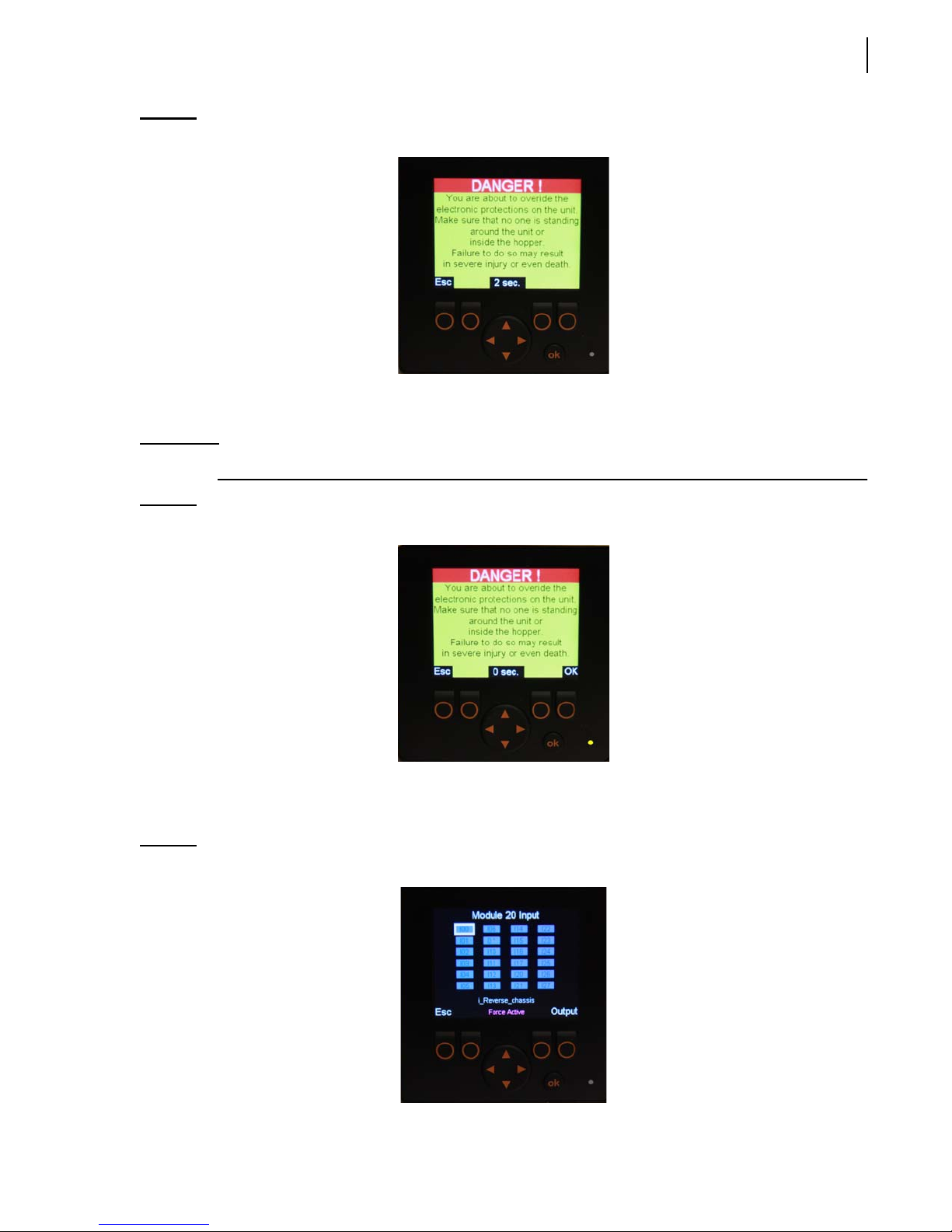
But before the Force page is displayed, a warning message appears on the screen (see Figure 3-10).
Page 63
Controls and Indicators 53
Figure 3-10
Warning message
This message stays on for 15 seconds. Then an “OK” prompt appears on the lower right-end corner
of the screen.
IMPORTANT: It is very important to read this message completely before accessing the next page.
Figure 3-11
Warning message w/ “OK” prompt
Press “OK” to go to the Force page or “Esc” to return to the preceding page.
After pressing “OK”, the Force page appears on the screen.
Figure 3-12
Force page (input)
Page 64
54 Controls and Indicators
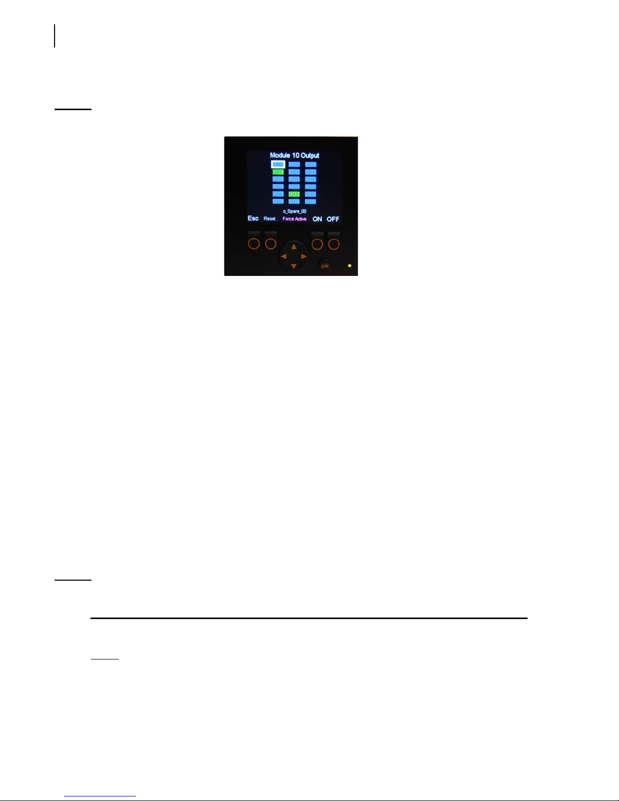
As no input function can be forced to be active or inactive, the operator must press the “Output”
button to go to the following page (see Figure 3-13).
Figure 3-13
The Force page allows the operator to force a function to be overridden. This is useful to enable an
inactive function or to disable an active function.
This page contains a set of rectangles. Each of these rectangles is numbered and relates to a specific
function of the truck.
Colors are used to indicate whether the corresponding function is active or not:
a blue rectangle means the corresponding function is inactive
a green rectangle means the corresponding function is active
Also:
Force page (output)
a red rectangle means there is a closed short-circuit
a yellow rectangle means there is an open circuit
A white-bordered rectangle means that this rectangle is selected. Use the directional arrows to select a
specific rectangle or function. When a rectangle is selected, a short description of the corresponding
function appears in the lower part of the screen.
After selecting a rectangle:
press “ON” to activate the corresponding function (rectangle turns from blue to green)
press “OFF” to deactivate the corresponding function (rectangle turns from green to blue)
press “RESET” to have the software monitor the status of the corresponding function
NOTE: To go from a module to another (e.g. from module 10 to 20), the operator must go back to the
Module I/O Status page (see Figure 3-7) and select module 20.
Press “Esc” to return to the preceding page.
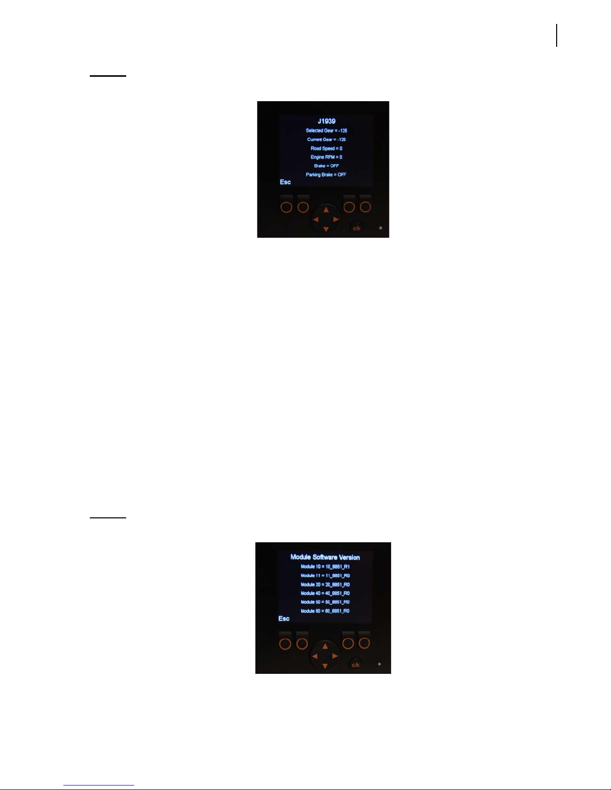
J1939
The J1939 page is useful when you need some specific information (e.g. current gear, road speed,
brake status).
Page 65
Controls and Indicators 55
Figure 3-14
Your vehicle is equipped with 2 different CAN-based communication buses:
the J1939 bus, which is used for the chassis equipment; and
the CANopen bus, which is used for the body.
These 2 communication buses are completely independent of one another, except for some specific
data that are transferred from the chassis J1939 bus to Labrie’s multiplexed system in order to be used
by this system. These specific data are the following:
selected gear
current gear
J1939 page
road speed
engine RPM
brake
parking brake
Press “Esc” to return to the preceding page.
Module Software Version
In this section, you will find the software version currently used by each of the modules installed on
the truck and by the master control module.
Figure 3-15
Program Version page
Press “Esc” to return to the preceding page.
Page 66

56 Controls and Indicators
Pump Usage (optional)
This section contains an optional hour meter that tracks pump usage for maintenance purposes.
Press “Esc” to return to the preceding page.
Auto-Dump (optional)
This section is used to reset both fork and arm potentiometers, which are part of the Auto-Dump
system. Before resetting, make sure the forks and arms are in their “home” position, then follow the
instructions shown on the display monitor. For more information, call LabriePlus (see To Contact
Labrie Plus on page 5).
Press “Esc” to return to the preceding page.
Time Adjust
This section allows you to set the Time and Date indicator.
Press “Esc” to return to the preceding page.
NOTE: To go back to the Main page or the Main Menu, press “Esc” as many times as necessary until
the desired page is displayed.
Page 67
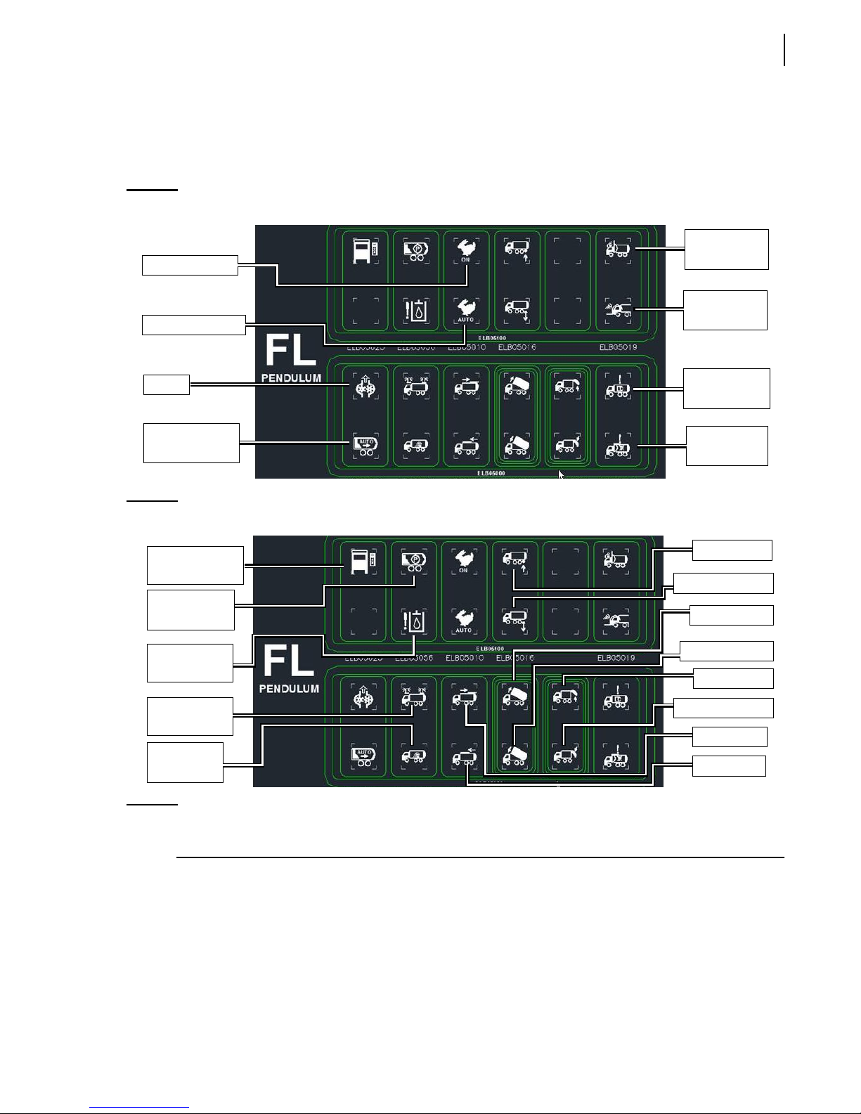
Control Panel
The control panel is located at the center of the cab (see Figure 1-5) for easy access during collection
and operation. Here is a description of all the controls and switches found on the control panel.
Controls and Indicators 57
Figure 3-16
Speed-up ON
Speed-up AUTO
Pump
Auto-packing
(optional)
Figure 3-17
Auxiliary
control power
Packer
retracted
Control panel (part 1)
Mirror light
(optional)
Canopy light
(optional)
Hopper door
open
Arms not
stowed
Control panel (part 2)
Tag axle up
Tag axle down
Body up
Hydraulic
alarm
Strobe lights
(optional)
Work lights
(optional)
Body down
Tailgate up
Tailgate Down
Roof open
Roof close
NOTE: The switches and controls that are on the control panel vary according to the options installed
on the vehicle.
Page 68

58 Controls and Indicators
Body Up Switch
Located on the control panel, this switch (see Figure 3-17) is used to raise the refuse body. Press and
keep down this switch to completely raise the body for unloading purposes or to raise it to a certain
height in order to either place the body props under the body or put them back in their home
position.
NOTE: When the body reaches a certain height, the Body Up switch will turn green while the Body
Down switch will turn blue.
Body Down Switch
Located on the control panel, this switch (see Figure 3-17) is used to lower the refuse body. Press and
keep down this switch to completely lower the body until it perfectly rests on the frame or on the
body props.
NOTE: When the body is completely lowered onto the frame, the Body Down switch will turn green
while the Body Up switch will turn blue.
Pump Switch
This switch (see Figure 3-16), also known as PTO switch, engages and disengages the hydraulic
pump, all the body functions (packer, tailgate) and the joystick that controls the arms.
Press the switch to activate the hydraulic pump (switch turns green).
Press the same switch again to deactivate the hydraulic pump (switch turns blue).
NOTE: If a safety interlock (e.g. due to access cover not closed) stops the hydraulic system from
running, the pump switch flashes red and the message “Pump: Hopper Door Not Closed”
appears on the display monitor.
NOTE: Do not close the main shut-off valve on the hydraulic tank even if the PTO switch is turned off.
The pump is always turning whatever the engine RPM. It is very important not to let the pump
run dry or without oil. Otherwise, the pump will be seriously damaged or even destroyed.
Page 69
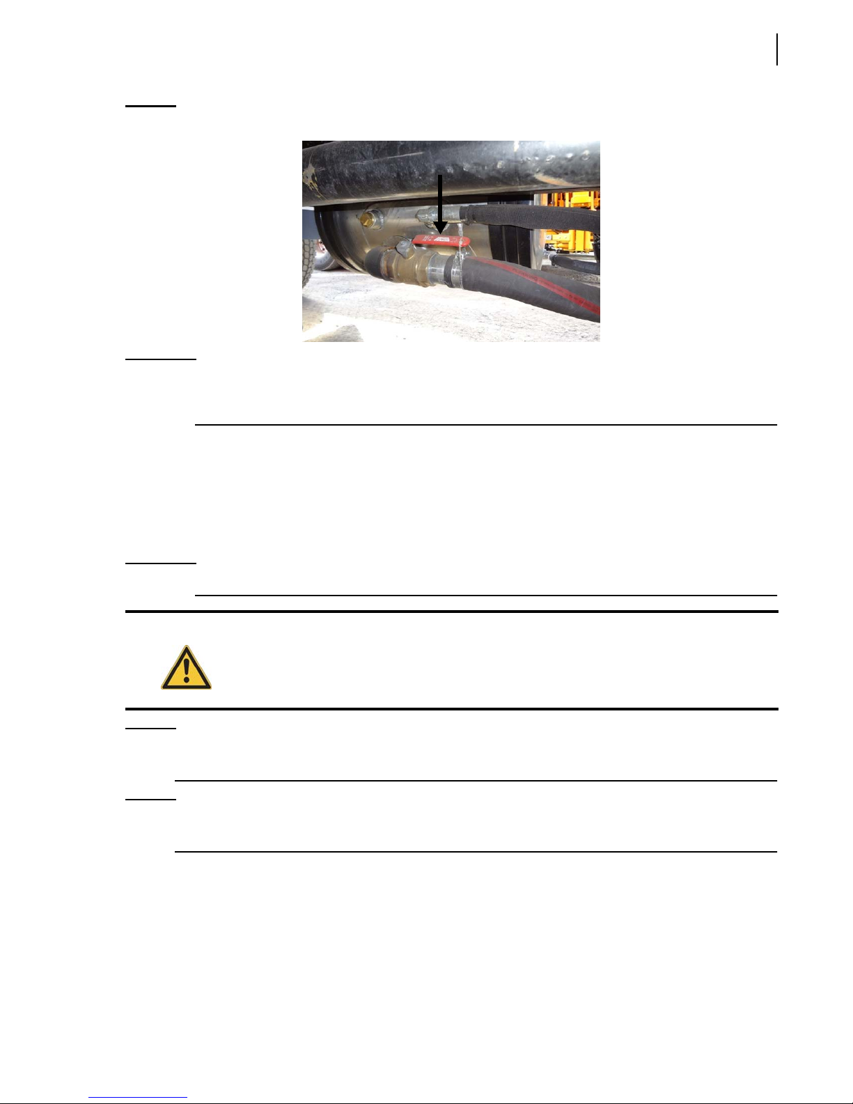
Controls and Indicators 59
Figure 3-18
IMPORTANT: In case of a leak in the hydraulic system, if the vehicle has to be driven somewhere else, take
Main shut-off valve
off the drive shaft between the pump and the engine. Call maintenance facility and refer to
the Maintenance Manual.
Tailgate Up Switch
This switch (see Figure 3-17) is used to raise the tailgate. Press it and keep it down to raise the tailgate
to the desired height.
Before using this switch, make sure that the truck is parked on safe level ground.
IMPORTANT: Remove both tailgate-locking pins before using this switch.
Warning!
Do not drive the vehicle when the tailgate is not fully closed.
NOTE: When the tailgate is unlocked both the in-cab buzzer (see Figure 3-19) and the backup alarm
will start sounding off. A red warning light, located on the buzzer, will also blink.
NOTE: Each time the tailgate is unlocked, the message “Tailgate Unlocked” appears on the display
monitor.
Page 70
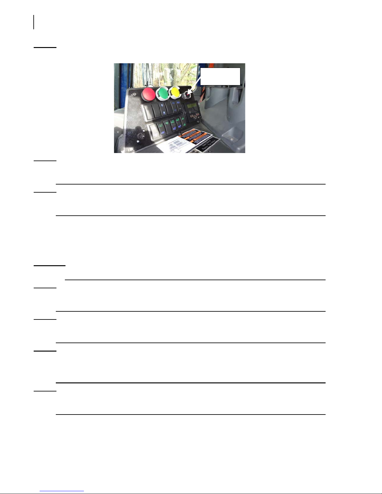
60 Controls and Indicators
Figure 3-19
Buzzer with red warning light
Red warning
light
NOTE: If the upward movement of the tailgate is stopped at any position except the fully open
position, both Tailgate Up and Tailgate Down switches will flash red.
NOTE: When the tailgate reaches the fully open position, the Tailgate Up switch will turn green while
the Tailgate Down switch will turn blue.
Tailgate Down Switch
This switch (see Figure 3-17) is used to lower the tailgate. Press it and keep it down to completely
close and lock the tailgate or to lower it until it rests on the tailgate safety prop.
IMPORTANT: When the tailgate is completely closed and locked, put both tailgate-locking pins back in place.
NOTE: If the downward movement of the tailgate is stopped at any position except the fully closed and
locked position, both Tailgate Up and Tailgate Down switches will flash red.
NOTE: Each time the tailgate is unlocked, the message “Tailgate Unlocked” appears on the display
monitor.
NOTE: When the tailgate is locked back, both the in-cab buzzer (see Figure 3-19) and the backup
alarm will stop sounding off. The red warning light, located on the buzzer, will also stop
blinking.
NOTE: When the tailgate is completely closed and locked, the Tailgate Down switch will turn green
while the Tailgate Up switch will turn blue.
Page 71
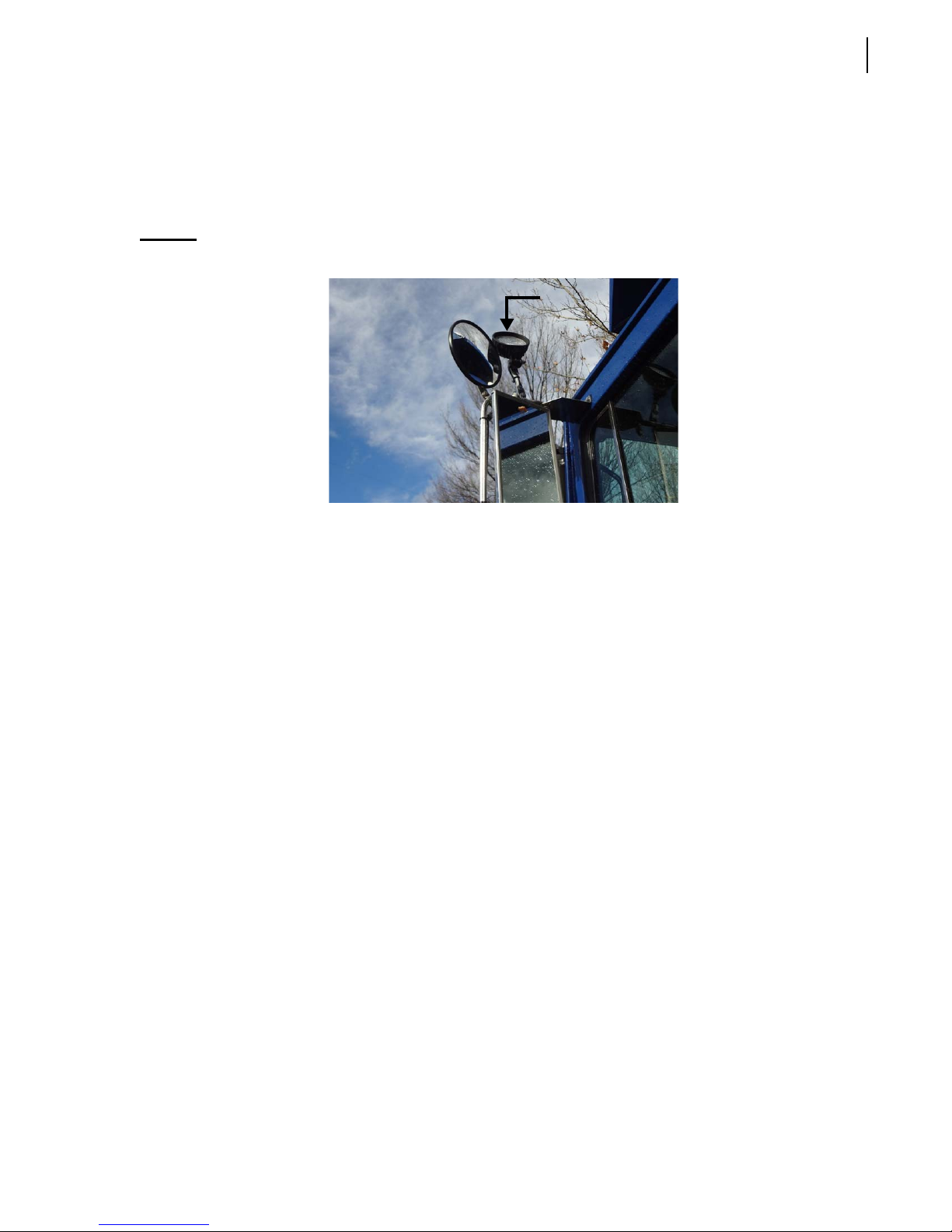
Mirror Light Switch (optional)
This switch (see Figure 3-16) turns on/off the light installed above the left-hand side rearview mirror.
Press the switch once to turn on the mirror light (switch turns green).
Press the switch again to turn off the mirror light (switch turns blue).
Controls and Indicators 61
Figure 3-20
Mirror light
Canopy Light Switch (optional)
This switch (see Figure 3-16) turns on/off the canopy light if installed on your vehicle.
Press the switch once to turn on the canopy light (switch turns green).
Press the switch again to turn off the canopy light (switch turns blue).
Strobe Light Switch (optional)
This switch (see Figure 3-17) turns on/off the strobe light if installed on your vehicle.
Press the switch once to turn on the strobe light (switch turns green).
Press the switch again to turn off the strobe light (switch turns blue).
Work Light Switch (optional)
This switch (see Figure 3-17) turns on/off work lights if installed on your vehicle.
Press the switch once to turn on work lights (switch turns green).
Press the switch again to turn off work lights (switch turns blue).
Auxiliary Control Power (optional)
Auxiliary controls, if installed on your unit, are located outside, directly behind the cab on the street
side (see Figure 3-21). To enable these controls, the operator must press the Auxiliary Control Power
switch on the control panel (see Figure 3-17).
A green switch means these controls are enabled.
A blue switch means these controls are disabled.
Page 72
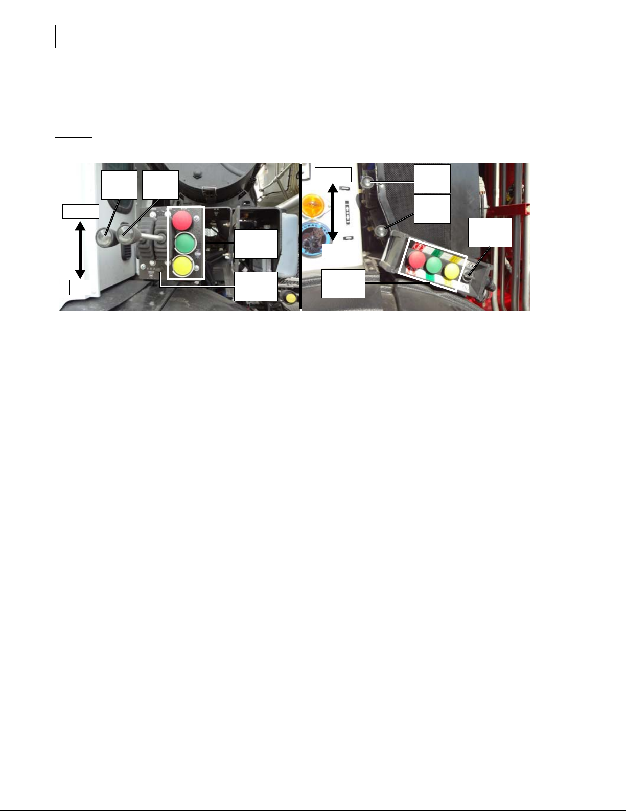
62 Controls and Indicators
Auxiliary controls include a dual handle joystick (see Figure 3-21) to operate both forks and arms and
a packer control station to operate the packer (see Figure 3-21). A throttle advance switch (or speedup) is also provided to speed up the packing process and the raising/lowering of the arms (see Figure
3-21).
Figure 3-21
Down
Up
Auxiliary controls
Forks
lever
Arms
lever
Packer
controls
Throttle
Advance
Auto-Packing Switch (optional)
The auto-packing switch (see Figure 3-16) enables the packer to automatically start cycling when the
arms pass the canopy on their way down.
Press the switch to initiate the automatic packing cycle (switch turns green).
Press the switch again to disable this feature (switch turns blue).
Down
Up
Packer
controls
Forks
lever
Arms
lever
Speed-
up
Forks Width Switches (optional)
These optional switches (see Figure 3-22) allow the operator to either increase or decrease the width
between both forks.
The upper switch is used to increase the width between both forks.
Press this switch and keep it pressed until the desired width is reached.
The lower switch is used to decrease the width between both forks.
Press this switch and keep it pressed until the desired width is reached.
Page 73
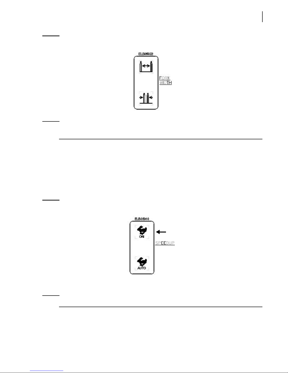
Controls and Indicators 63
Figure 3-22
Forks width switches
NOTE: If this optional feature is available on your unit, these switches are located on the control
panel.
Speed-Up Switches (optional)
These switches (see Figure 3-16) engage/disengage the optional speed-up feature which is used to
increase the engine speed up to 1500 RPM whenever a pack or an auto-pack cycle is initiated.
The upper switch is used to engage the speed-up function which increases the engine speed until
disengaged.
Press this switch to engage the speed-up function (switch turns green).
Figure 3-23
Speed-up “ON”
Press this switch again to disengage the speed-up function (switch turns blue).
NOTE: The unit transmission must be in neutral before this speed-up switch can be turned on.
The lower switch is used to activate the auto setting for the speed-up function and increase the
engine speed up to 1500 RPM during packing and auto-packing cycles.
Press this switch to engage the “AUTO” speed-up function (switch turns green).
Page 74
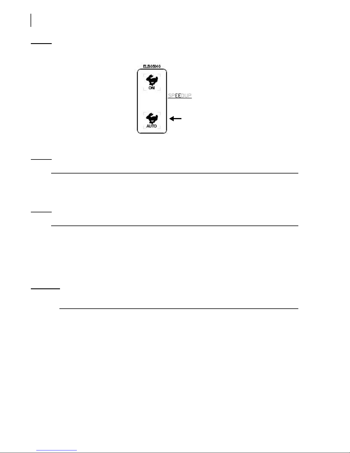
64 Controls and Indicators
Figure 3-24
“Auto” speed-up
Press this switch again to disengage the “AUTO” speed-up function (switch turns blue).
NOTE: The unit transmission must be in neutral before this speed-up switch can be turned on.
Top Door Switches (Roof Open/Roof Close)
Located on the control panel, these switches (see Figure 3-17) are used to open/close the top door.
NOTE: The top door must be fully open to dump refuse into the hopper.
The upper switch is used to open the top door.
Press this switch and keep it pressed until the top door is completely open. Once the top door is
fully open, the switch turns green. Refuse can now be dumped into the hopper.
The lower switch is used to close the top door.
Press this switch and keep it pressed until the top door is completely closed. When the top door is
fully/partially closed, both Top Door switches are blue.
IMPORTANT: Dumping refuse into the hopper with the arms and forks can only be done when the upper switch is
green-lighted.
Tag Axle Switches (Tag Axle Up/Tag Axle Down)
Located on the control panel, these switches (see Figure 3-17) are used to raise/lower the tag axle.
Press the upper switch to raise the tag axle.
The switch turns from blue to green. The lower switch is blue-lighted.
Press the lower switch to lower the tag axle.
The switch turns from blue to green. The upper switch is blue-lighted.
Page 75

Controls and Indicators 65
Hydraulic Alarm Switch (optional)
The hydraulic alarm switch is located on the in-cab control panel (see Figure 3-17).
When this switch is engaged (green-lighted), the system continually monitors the temperature and
level of hydraulic oil. If the oil temperature gets too high or the level of hydraulic oil gets too low, the
hydraulic alarm switch will turn red, meaning that a correction must be applied quickly.
NOTE: This switch should always be engaged.
Packer Retracted Indicator Light
This indicator light is located on the in-cab control panel (see Figure 3-17).
If this indicator light is green, this indicates that the packer is completely retracted.
If this indicator light is red, this indicates that the packer is not completely retracted.
NOTE: The packer must be completely retracted to allow dumping into the hopper.
Hopper Door Open Indicator Light
This indicator light is located on the in-cab control panel (see Figure 3-16).
If this indicator light is green, this indicates that the hopper door is closed.
If this indicator light flashes red, this indicates that the hopper door is not closed.
NOTE: No hydraulic function is possible when the hopper door is not closed. In such a situation, the
pump switch on the control panel (see Figure 3-16) also flashes red.
Arms Not Stowed Indicator Light
This indicator light is located on the in-cab control panel (see Figure 3-16).
If this indicator light is green, this indicates that arms and forks are adequately stowed.
If this indicator light is red, this indicates that arms and forks are not adequately stowed.
IMPORTANT: Never drive this vehicle when this indicator light is red-lighted.
In-Cab Packer Control Station
The WITTKE PENDULUM™ has a packer control station located on the cab console. Here is a
description of all three push-buttons that are on the packer control station.
Page 76
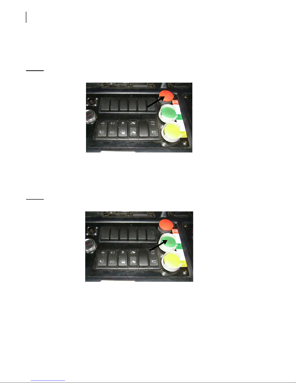
66 Controls and Indicators
Stop Push-Button (red)
The Emergency Stop button (see Figure 3-25) will stop all hydraulic functions on the truck (tailgate,
pendulum packer, etc.). By pressing the red button, the packer will stop where it is. The same button
has to be manually pulled back to reactivate the hydraulic system.
Figure 3-25
Stop push-button
Pack Push-Button (green)
This push-button activates the packing cycle.
Press this button once to activate the pendulum packer. Tailgate must be closed and locked to
allow the automatic return of the packer to the “home” position.
Figure 3-26
Pack push-button
Retract Push-Button (yellow)
This push-button (see Figure 3-27) returns the pendulum packer to its “home” position when you
are packing a load.
Press this button once to bring the pendulum packer back to its “home” position (tailgate must be
closed).
Page 77
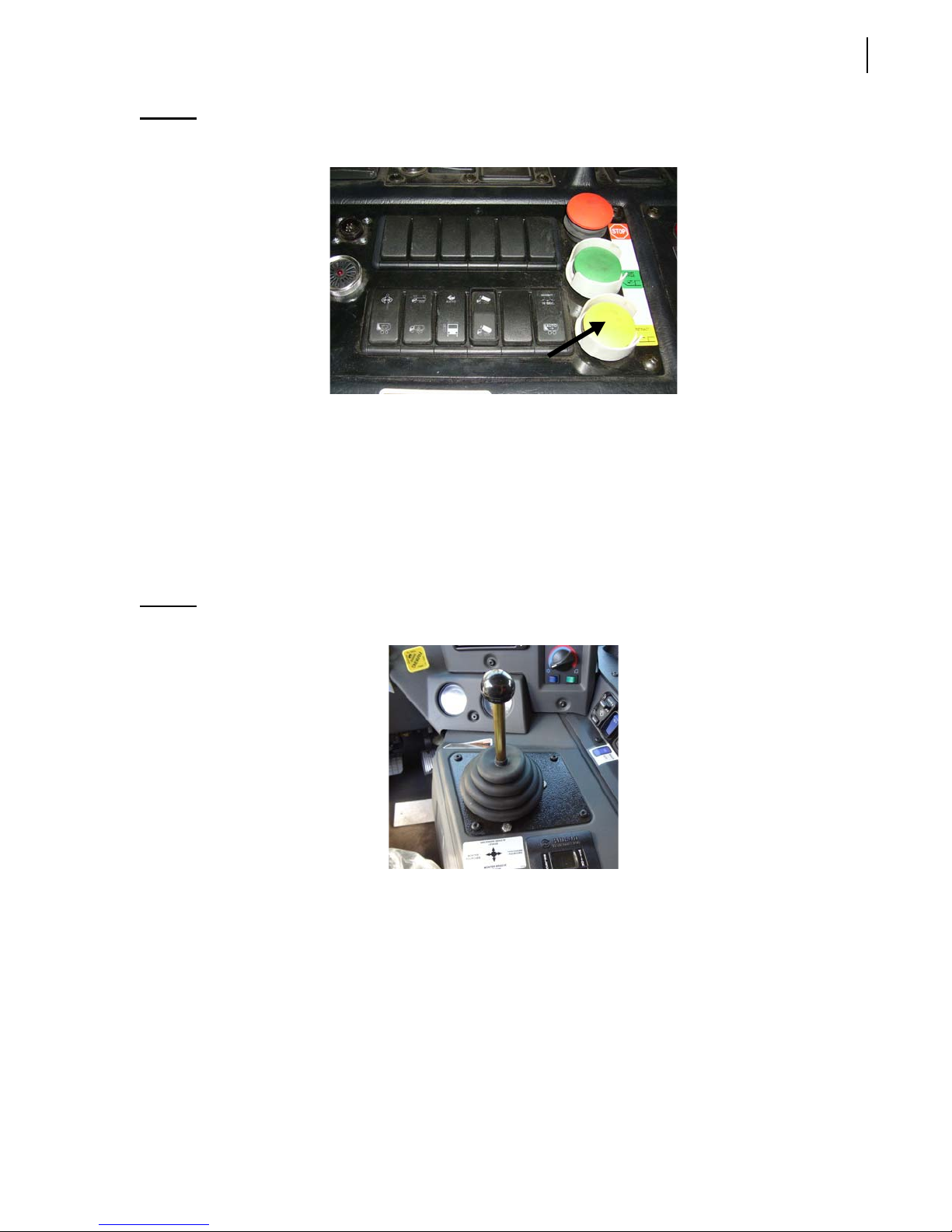
Controls and Indicators 67
Figure 3-27
Retract push-button
Joystick Controls
In-Cab Joystick
Located on the console at the center of the cab, this pneumatic joystick (see Figure 3-28) controls
both arms and forks. It operates at 90° and 45° angles. As a result, you can perform two functions at
the same time. For example, you can lower the arms and forks simultaneously.
Figure 3-28
Shift the joystick forward to lower the arms only.
Shift the joystick to the position between the Arms Down and Forks Down to lower both the arms
and forks (see Figure 3-29).
Shift the joystick to the left to lift the forks only (see Figure 3-29).
Shift the joystick to the position between the Forks Up and Arms Up to raise both the forks and
arms (see Figure 3-29).
Shift the joystick backward to raise the arms only.
Shift the joystick to the right to lower the forks only.
In-cab joystick
Page 78
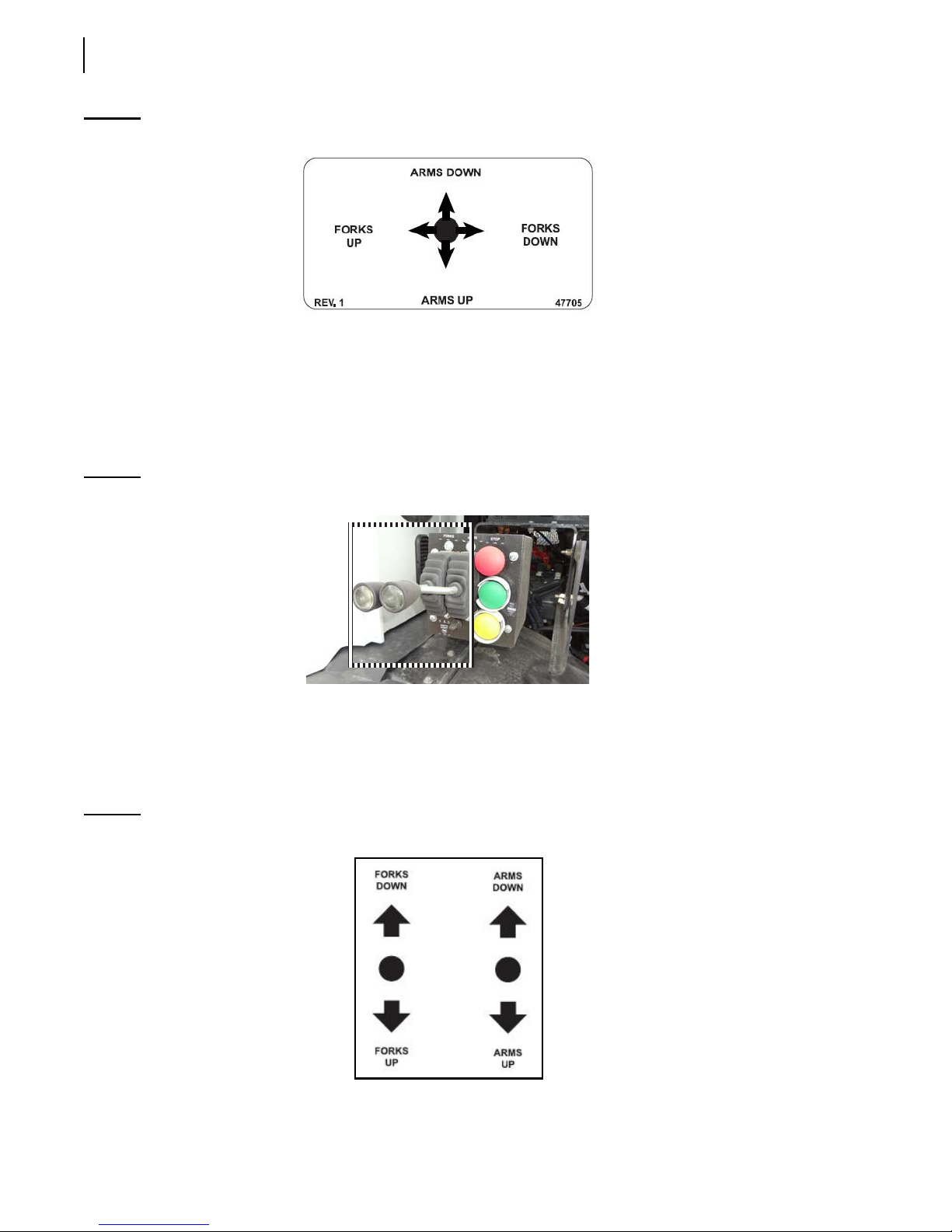
68 Controls and Indicators
Figure 3-29
Joystick functions
Outside Dual Lever Joystick (optional)
This optional pneumatic joystick uses two levers to control the arms and forks: the right-hand lever
controls the arms and the left-hand lever controls the forks. While these are separate controls, you
may still perform two functions at the same time. For example, you can lower the arms and forks
simultaneously.
Figure 3-30
Dual lever joystick
Shift the Fork control downward to raise the forks.
Shift the Fork control upward to lower the forks.
Shift the Arm control downward to raise the arms.
Shift the Arm control upward to lower the arms.
Figure 3-31
Dual lever joystick functions
Page 79
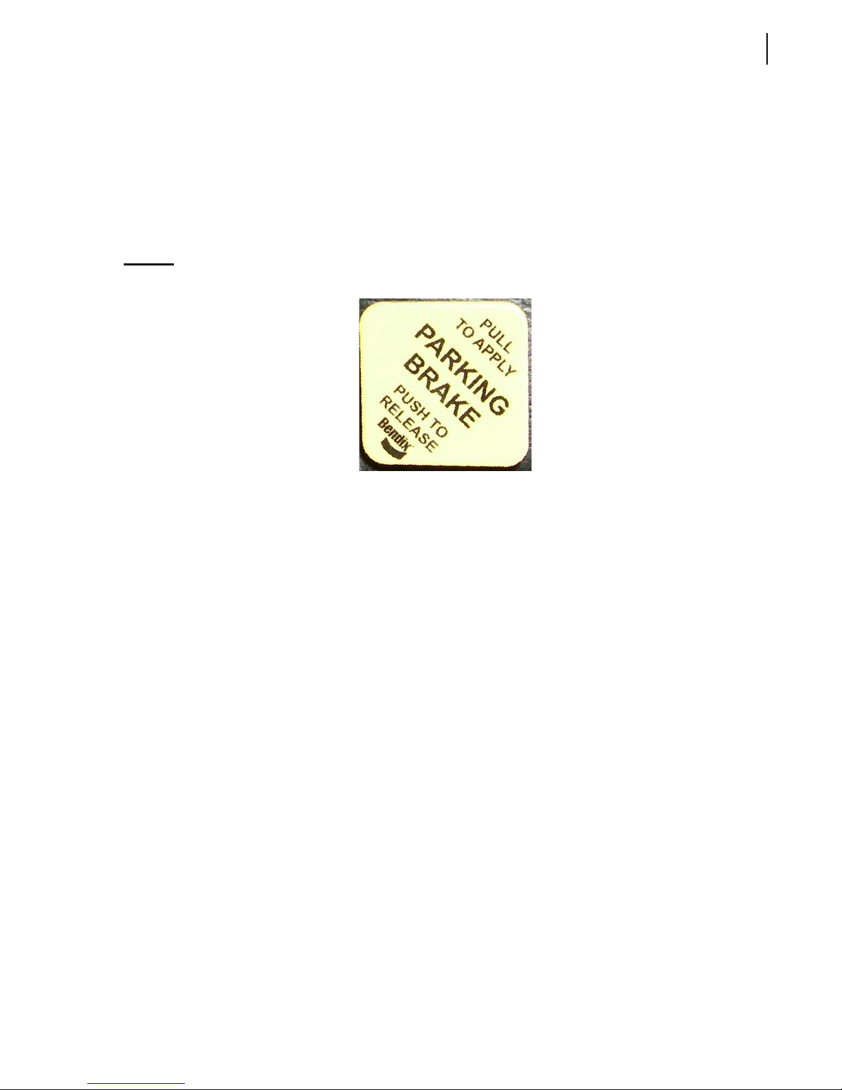
Cab Dashboard
The following is a description of the controls and buttons located on the dashboard.
Parking Brake
The parking brake must be used every time the WITTKE PENDULUM™ is stopped on idle position
other than the regular traffic stops (see Figure 3-32).
Controls and Indicators 69
Figure 3-32
Parking brake
Page 80

70 Controls and Indicators
Page 81

Operating the
ITTKE PENDULUM™
W
The different methods, procedures and necessary
actions to operate the W
presented in this section.
ITTKE PENDULUM™ are
4
Warning!
Before operating the W
operator must be completely familiar with all safety
procedures, and the location, operation and functions
of all controls and indicators related to the operation of
the unit.
You must complete the daily inspection before starting
the vehicle. It is your responsibility to report any
malfunctions or concerns to your supervisor and
maintenance personnel.
Consult with your supervisor for specific rules of
driving the W
Obey all speed restrictions and regulations.
Daily Inspection
Always read and understand the
Operator’s Manual before operating the
unit.
ITTKE PENDULUM™, the
ITTKE PENDULUM™.
Approaching the Vehicle
As you approach the vehicle, look for any object under
or against the vehicle and check the surroundings for
people, other vehicles, as well as ground and overhead
obstructions. Ensure that the truck is parked at the
most convenient place where you will have all the
clearance required to perform a complete start-of-theday inspection. During the daily inspection, look for
any structural damage. Inspect tires and check the
hydraulic tank for air leaks.
Visual Inspection
Before starting the vehicle, the operator MUST
perform a visual inspection of the truck.
Page 82

72 Operating the WITTKE PENDULUM™
Tasks to be performed during daily visual inspection:
Ensure the engine is not running and the parking brake is set.
Ensure the cleanliness of lamps, safety decals, camera lenses, mirrors, windows, and the vehicle in
general.
Ensure that safety equipment is present (i.e. fire extinguisher, first aid kit).
Ensure there is no structural damage.
Ensure that body mounts to chassis are tight and that there are no cracks on it or on the structure
around it.
Ensure that there is no unusual wear, distortion, cracking, leaning, leaking on the vehicle.
Ensure that hydraulic oil level (sight gauge on tank) is as recommended (cylinders must be
collapsed).
Ensure that the hydraulic cylinders do not leak, and ensure mounting pins are secure.
Ensure the hydraulic tank shut-off valve is fully open.
Ensure there are no mechanical problems: structure, rollers, hinges, door locks, wear items, etc.
Report any defective system to maintenance personnel.
Ensure there are no leaks, cracks or other types of problems on the frame area, fuel tank, hydraulic
tank, air tanks (air tanks must be drained every day), cleaning trap and wheels.
Ensure the tailgate is fully closed and locked, BOTH tailgate safety pins are in place and rollers are
on main locking pins.
Once the visual inspection is over, you must start the engine to check if the systems are working
properly.
Starting the Vehicle
To start the WITTKE PENDULUM™:
1. Before starting the engine, check the following items:
1 a. Transmission shifter is on neutral.
1 b. Parking brake is on (see Parking Brake on page 69).
1 c. Hydraulic system is off (see Pump Switch on page 58).
2. Start the vehicle as stated in the chassis manufacturer’s manual.
3. Switch ON the pump to engage the hydraulic system (the air pressure must be at a minimum of
70 psi). See Figure 3-16.
4. Turn on all light switches.
5. If required, move the truck to an appropriate area to perform daily inspection.
6. Report any defective system to the maintenance personnel.
Body Inspection Procedure
Exit the cab to continue your inspection. Bring a rag along to clean all accessible lights, labels, camera
lenses, etc. Check for mechanical problems: rollers, hinges, door locking mechanisms, wear items,
etc. Report any defective system to the maintenance personnel.
Page 83
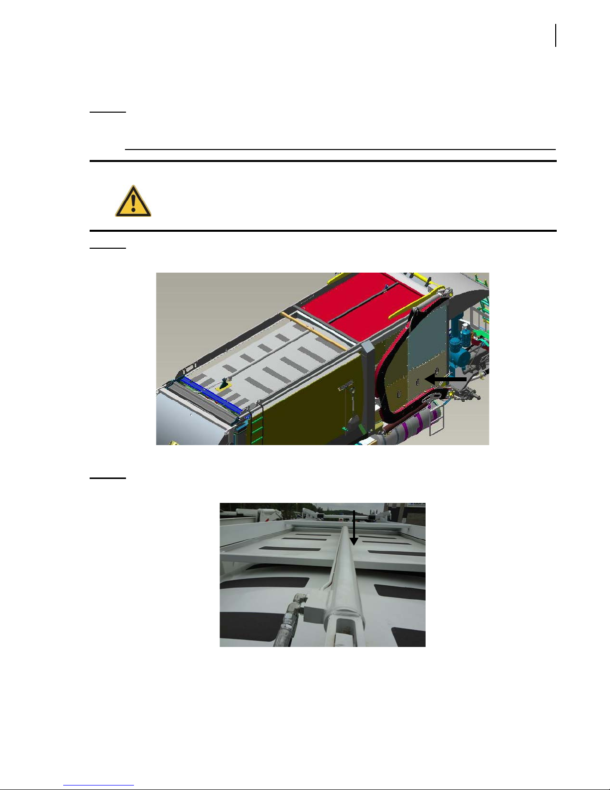
Operating the WITTKE PENDULUM™ 73
Body inspection procedure:
1. Check the hopper door for proper latching (see Figure 4-1).
NOTE: When the hopper door is open, the hydraulic pump is disabled. This door MUST be closed for
the hydraulic pump to function.
Danger!
Figure 4-1
Never attempt to reach inside the hopper area while the packer is in motion. Severe injury or
death may occur.
Hopper door
2. Go back in the truck and open the top door completely.
Figure 4-2
3. Press the green push-button on the in-cab packer control station (see Figure 3-26) to activate the
4. Use the joystick on the in-cab console (see Figure 3-28) to check for proper operation of the
Top door
packer for a full cycle.
arms and forks.
Page 84
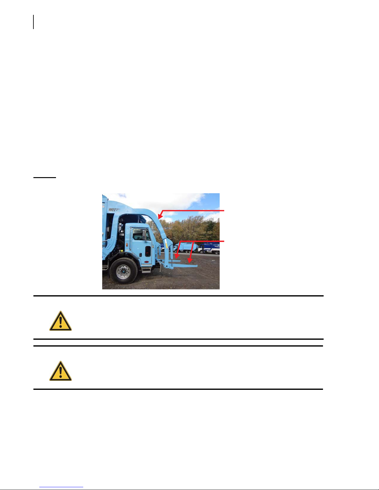
74 Operating the WITTKE PENDULUM™
5. Check if the tailgate safety pins are in place. If they are not then you need to put them in place to
lock the tailgate properly.
6. As you walk along the side of the truck, clean all safety decals.
7. Check the frame area, fuel tank and air tanks (air tanks must be drained every day), cleaning traps
and wheels for leaks, cracks or other type of problems.
8. At the front end, check lights and mirrors.
9. Go around and check lights, clean camera lenses, decals, lights, etc.
10. Check for hydraulic leaks.
Arm Inspection Procedure
On a daily basis, perform a visual inspection of the lifting arms and forks, looking for leaks, cracks or
premature wear of the moving parts. Refer to the Lubrication section in the Maintenance Manual for
detailed greasing points.
Figure 4-3
Lifting arms and forks
Danger!
Warning!
Arm
Forks
Do not stand directly in the path of the arm while performing the inspection.
Apply the lockout/tagout procedure at all times. See Locking Out and Tagging Out the
Vehicle on page 36.
Apply the following inspection procedure:
1. Make sure to park the vehicle on safe level ground.
2. Start the engine and engage the hydraulic pump (see Pump Switch on page 58).
3. Fully lower both lifting arms and extend both forks as shown in Figure 4-3.
Page 85
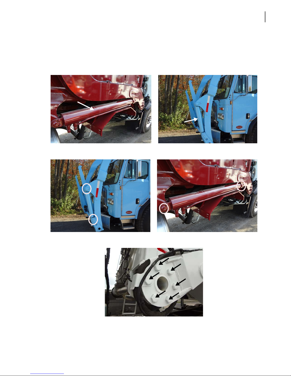
Operating the WITTKE PENDULUM™ 75
4. Turn off the hydraulic pump (see Pump Switch on page 58) and the engine.
5. Ensure that the parking brake is applied and the vehicle is tagged out for maintenance purposes
(see Locking Out and Tagging Out the Vehicle on page 36).
6. Perform a visual inspection of the following items:
• cylinders
• pivots
• mounting bolts
• Hoses and connections
Page 86
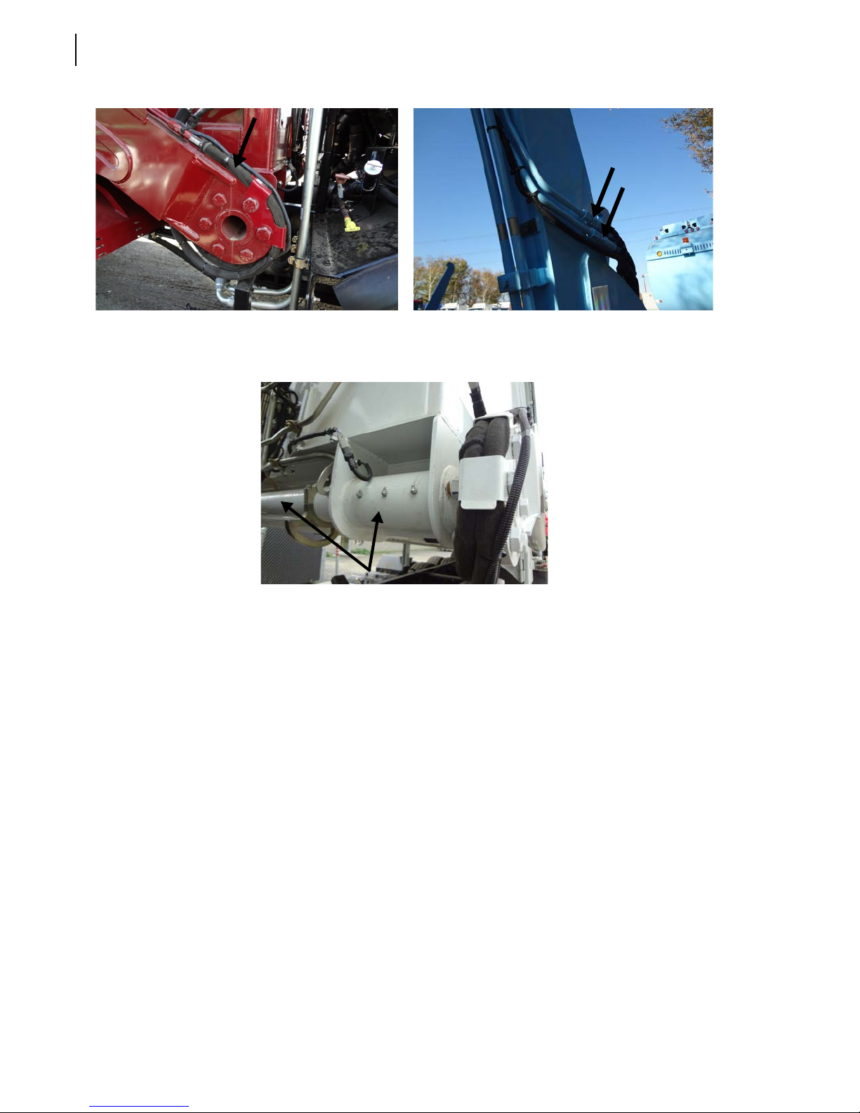
76 Operating the WITTKE PENDULUM™
• Check for loose nuts and bolts
• Torque tube support and shaft
• Check proximity switches for proper operation. Refer to the Maintenance Manual.
Page 87
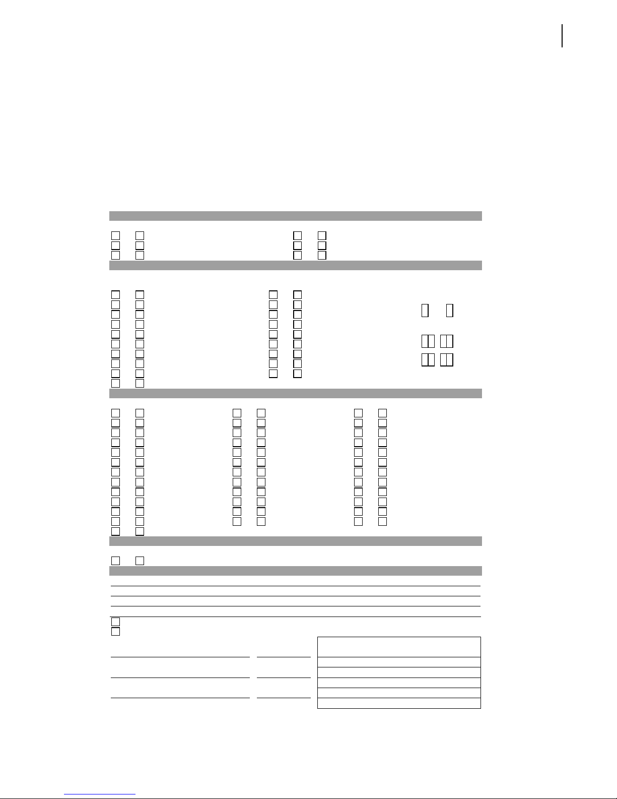
Operating the WITTKE PENDULUM™ 77
Inspection Sheet
The following is an example of an inspection sheet. The operator MUST follow the inspection sheet
provided by his employer. If the employer does not have any, ask for his permission before using this
example sheet.
VEHICLE CONDITION REPORT
Date: _________________ Unit: _______________________________
Driver: ____________________ Demo: _______________________
Engine Hrs in: _______________ Engine Hrs out: __________________
Mileage in: _________________ Mileage out: ____________________
Start Time: _____________________________ Finish Time: _____________________________
PRE POST Amount Added PRE POST Amount Added
Engine Oil Qt. _______ Fuel Gal. ________
Hydraulic Oil Qt. _______ Transmission Qt. _________
Coolant Qt. _______ Water Qt. _________
If items need repair, check below and describe. TIRES
PRE POST PRE POST Indicate any defects.
All gages/gage lights Cab horn
Low oil pressure Exterior back-up horn
Low oil warning light/buzzer Windshield cracks
Seat and seat belt Windshield wipers
Clutch free play (Juggler) Heat/Defrost
License/registration papers Reflective triangles
Service brakes adjusted Steering play
Parking brakes operational Radio
Low air warning light/buzzer Camera
Air compressor adequate
VISUAL BODY WALK-AROUND
PRE POST PRE POST PRE POST
Battery disconnect Electrical wiring Compactor working
Body damage Fire Extinguisher Hydraulic leaks
Cab damage Fuel tank/lines Hydraulic pressure
Air lines Exhaust Hydraulic hoses
Air compressor Engine Wheel/Rims
Air dryer Starter Seals
Head lights Turn signal Transmission
Marker lights Camera Mirrors
Brake lights Cable/Hooks Radiator
Suspension Arm Safety devices
Hopper clean Body clean Safety decals
Tailgate Packer Cart tipper
Safety Interlock switches
FLUID LEVELS
CAB INSPECTIONS
PRE POST
No Defects – Vehicle Condition Satisfactory
Above defects corrected
Above defects need not be corrected for the safe operation of vehicule.
DRIVER’S SIGNATURE DATE
DISTRIBUTOR SIGNATURE DATE
DRIVER’S REVIEW SIGNATURE DATE
DEFECT DESCRIPTION
Mechanic’s Comments :
Page 88
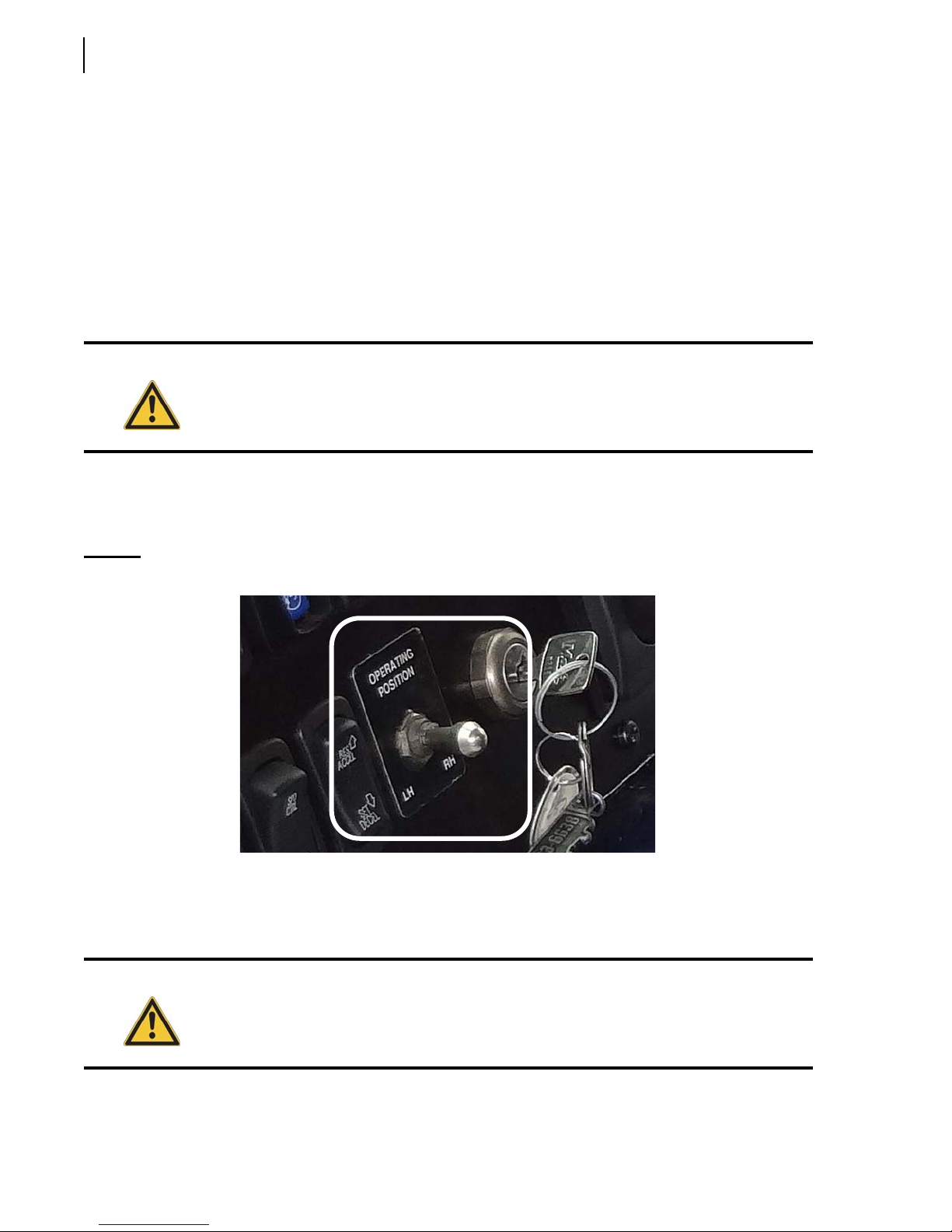
78 Operating the WITTKE PENDULUM™
Right-Hand Side Driving Position (optional)
If your unit is equipped with a right-hand side driving position, the following general procedure must
be followed when you need to change driving positions.
Before you operate your front-loader using the optional right-hand side driving position, take the
time to read the chassis manufacturer’s manual so that you can exactly know what you have to do.
Also, check with your supervisor for regional rules about speed and safety restrictions.
When changing driving positions, follow these steps (general procedure):
1. Stop the vehicle and set the parking brake.
Warning!
2. Turn off the hydraulic pump (see Pump Switch on page 58).
3. Move to the desired driving position (LH or RH).
4. Shift the OPERATING POSITION switch to the desired position (LH or RH).
Figure 4-4
O
PERATING POSITION
Set the parking brake before leaving the cab for an extended period of time or when
stopping on an incline. Do not rely on work brake.
switch
5. Adjust mirrors and monitor to the chosen driving position.
6. Start the engine.
7. Turn on the hydraulic pump (see Pump Switch on page 58).
Warning!
8. Adjust the front loader arms to a position suitable for travel to the next stop.
Use the parking brake when leaving the cab for an extended period of time rather than the
right-hand side work brake (if equipped). Consult the chassis OEM.
Page 89
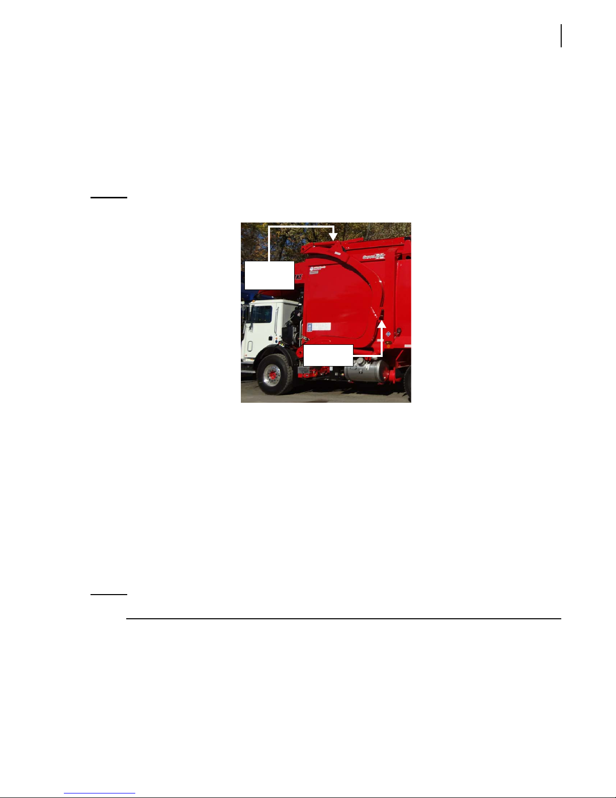
Position of the Lifting Arms
Collection Mode
To correctly position the arms between two pick-ups:
1. Raise the arms until they rest on the rubber bump stops.
2. Retract the forks fully.
Operating the WITTKE PENDULUM™ 79
Figure 4-5
Arms correctly positioned
En Route
Consult with your supervisor for specific rules of driving the front loader in your location.
Please remember the following important points:
The tailgate MUST be fully closed with tailgate safety pins in locking position.
Forks fully
retracted
Bump stop
Obey speed restrictions and regulations if driving from the right-hand side.
Overheight Caution
In some locations, the front loader may be overheight when the arms are in the full up travel position.
Consult local regulations or confer with your supervisor if unsure.
NOTE: Before passing under an overpass, be aware of the required clearance.
Units when not in Collection Mode
To correctly position the arms, do the following:
1. Raise the arms until they rest on the rubber bump stops (see Figure 4-6).
Page 90
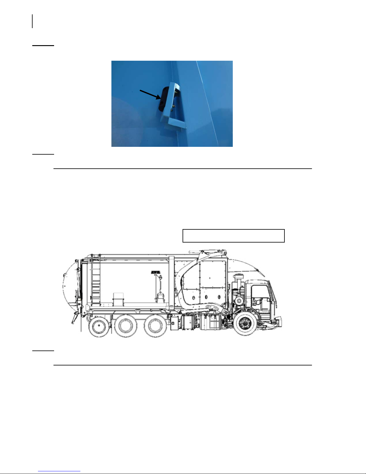
80 Operating the WITTKE PENDULUM™
Figure 4-6
Rubber bump stop
NOTE: Be aware of the required overhead clearance at all times.
2. Retract the forks fully until the Arms not Stowed indicator light on the console panel turns green
(see Figure 3-16).
3. Close the top door (see Top Door Switches (Roof Open/Roof Close) on page 64).
4. Turn off the hydraulic pump (see Pump Switch on page 58) to reduce the engine load between
stops.
Arms and forks in safe driving position
NOTE: Switch the hydraulic pump to OFF if you route destination is more than 1 mile (1.6 km) away.
Page 91
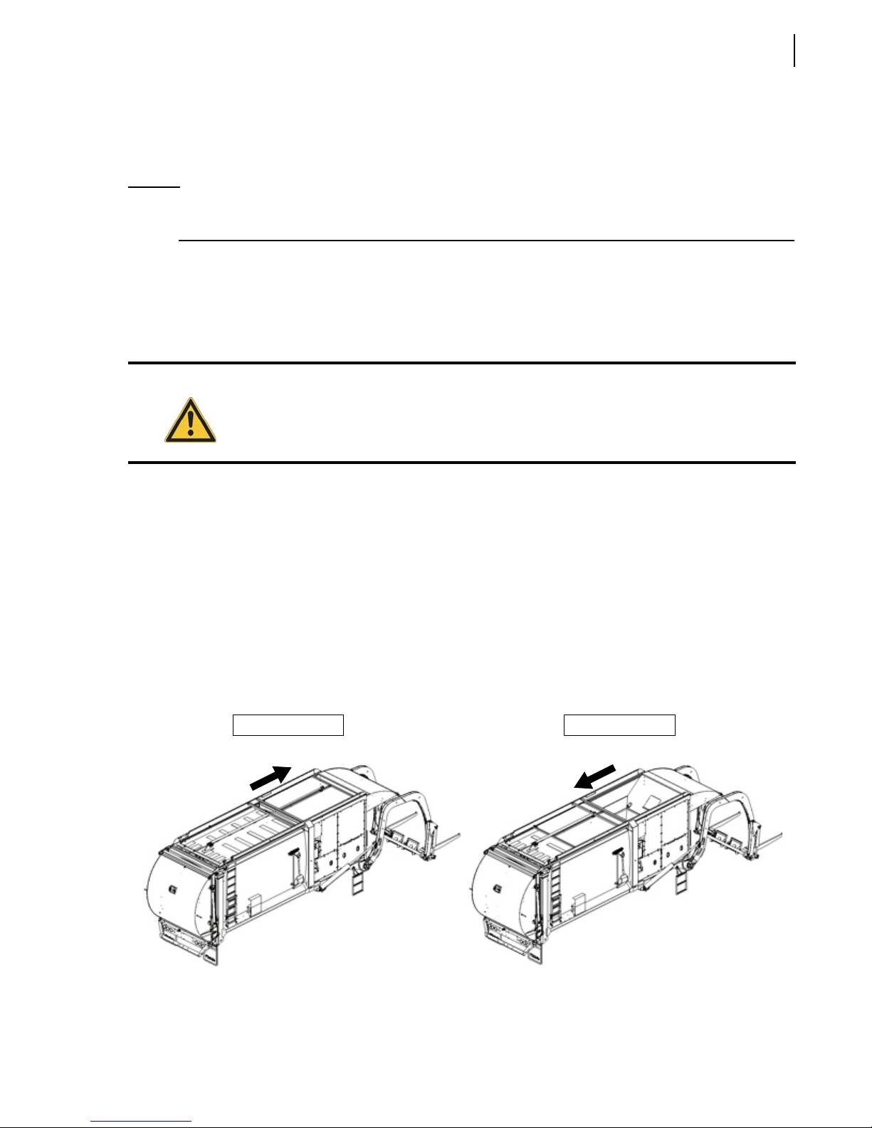
Operating the WITTKE PENDULUM™ 81
Exhaust Regeneration Process
To get more details about exhaust regeneration process, please refer to the chassis manufacturer’s
documentation.
NOTE: During the exhaust regeneration process, the operator must raise the arms until they rest on
the rubber bump stops. Failure to do so will cause damage that are not covered by warranty.
Collecting Refuse
You should carefully follow the instructions below to ensure a safe and efficient collection. All the
safety notions mentioned herein are of outmost importance and you should obey them at all times.
Danger!
Be sure there is enough clearance to handle the container safely from the way up to the way
down. Make sure nobody is near the vehicle.
Planning your Route
It is important to plan your route in order to be efficient. Planning your route will shorten your
collection time and prevent from being caught in a traffic jam.
Refuse Collection Procedure
To collect refuse with your WITTKE PENDULUM™ unit, do the following:
1. Turn on the hydraulic system (See Pump Switch on page 58) and fully open the top door (See
Top Door Switches (Roof Open/Roof Close) on page 64).
Closed top door Open top door
Page 92
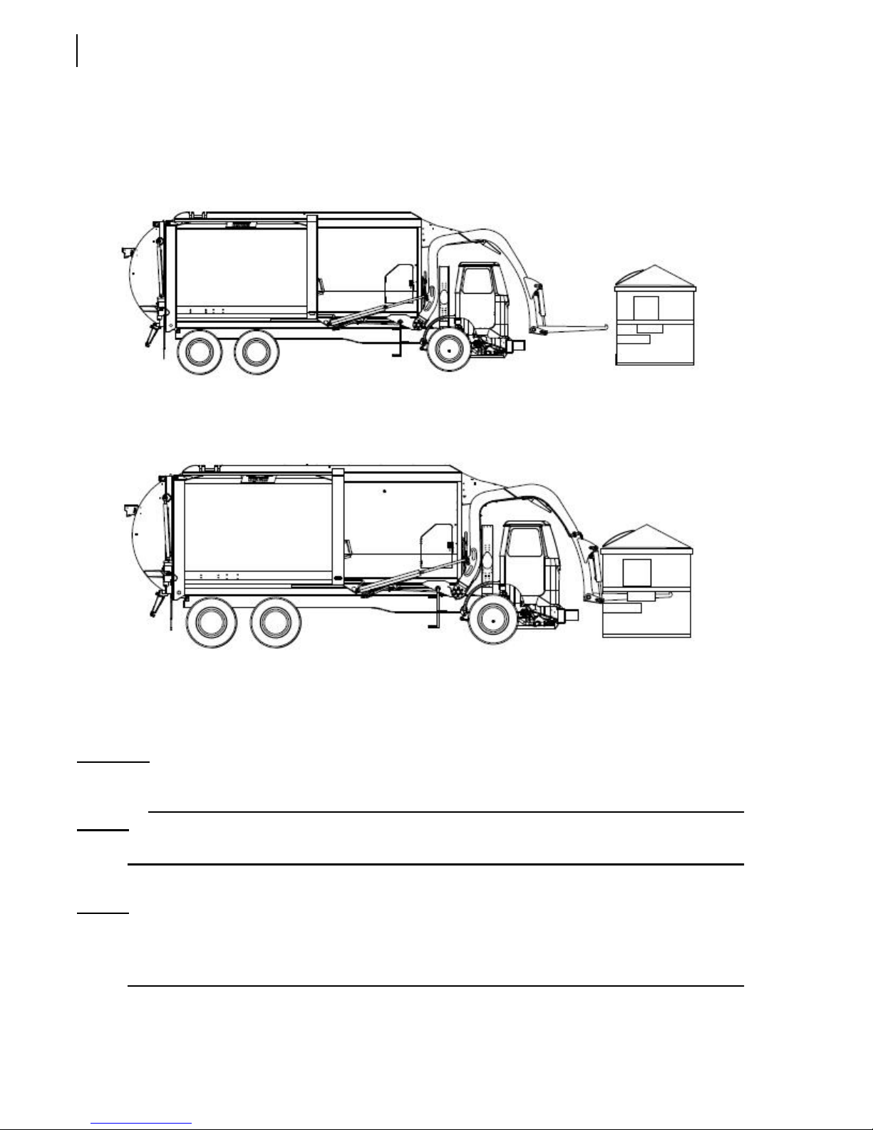
82 Operating the WITTKE PENDULUM™
2. Fully retract the pendulum packer (to its “home” position). The Packer Retracted indicator light
on the console panel (See Packer Retracted Indicator Light on page 65) will turn green when the
packer is fully retracted.
3. Position the front loader to approach the front of the container (see next illustration).
4. Adjust the arms and forks as required to securely engage the container.
5. Put the transmission to neutral and apply the parking brake (See Parking Brake on page 69).
6. Raise the container while adjusting the forks to ensure the container clears the cab guard and
canopy, and refuse does not spill before it reaches the hopper. Raise the container until the arms
rest on the rubber bump stops.
IMPORTANT: Do not tip the container much more than 45 degrees. The container may slip off the forks and fall
into the hopper.
NOTE: The forks may be cycled up and down in short movements to help empty the container.
7. Adjust the forks to a 45-degree angle to dump the content of the container into the hopper.
NOTE: While raising the arms and consequently the container, the operator should adjust the forks to
make sure the container clears the cab and canopy, and it does not prematurely spill or dump
refuse over the cab.
Page 93
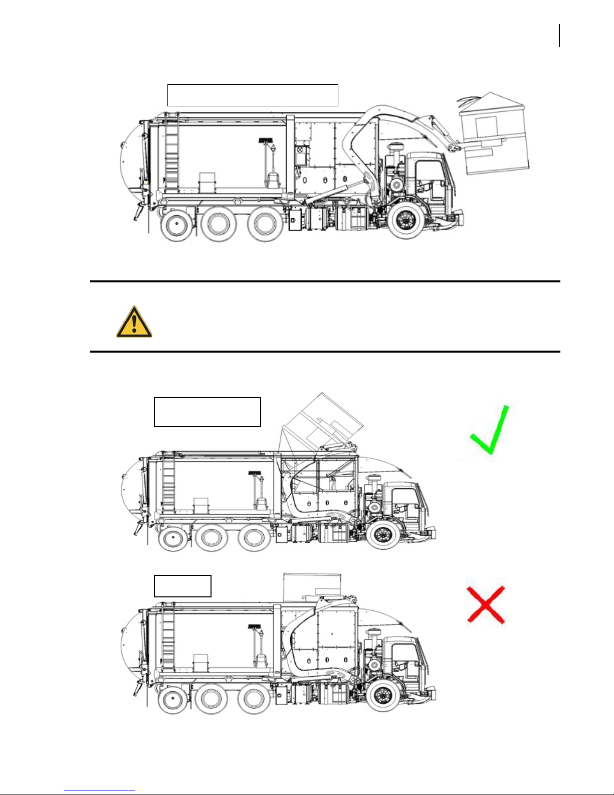
Operating the WITTKE PENDULUM™ 83
You must adjust the forks at this height
8. Tilt the container out of the hopper, lower the arms and return the container to the ground.
Danger!
Be sure there is enough clearance to dump the container’s content into the hopper. Make
sure nobody is near the vehicle during the operation.
Correct way to dump a
container
Wrong way
Page 94

84 Operating the WITTKE PENDULUM™
NOTE: At this point you can press the Pack button on the control panel (See Pack Push-Button (green)
on page 66) to move the pendulum packer down and pack the recently dumped refuse into the
body. The packer is allowed to pack during travelling.
Packing Refuse
When the hopper is full, the packer of the WITTKE PENDULUM™ helps you clear the hopper area by
packing refuse into the body.
Packing refuse can be done in two ways:
by pressing the Pack button — With the use of the Pack button on the control panel (see Pack
Push-Button (green) on page 66), you can control the pendulum packer’s sweep cycle. You can
however stop the packer by pressing the Stop button (red) and retract it by pressing the Return
button (yellow) at any point during the sweep cycle.
by using the Auto-Packing mode — Working in this mode, the pendulum packer’s sweep cycle
is fully automated and is triggered by the lowering of the arms. You can, however, stop the packer
by pressing the Stop button (red) or retract it by pressing the Return button (yellow) at any point
during the sweep cycle (see Auto-Packing Switch (optional) on page 62).
NOTE: Use the Auto-Packing mode when time is of the essence and you are secure in allowing the
W
ITTKE PENDULUM™ control of the pack cycle. This mode provides you with a hands-off
method of packing refuse while allowing you to focus on driving the front loader to the next
stop.
Packing Refuse Using the Pack Button
The pendulum packer should be cycled every time the content of a container is dumped into the
hopper.
To activate the packing cycle:
1. Turn on the hydraulic system (see Pump Switch on page 58).
NOTE: When the hopper door is open (see Figure 4-1), the hydraulic pump is disabled. This door
MUST therefore be closed properly in order for the hydraulic pump to be activated. The
Hopper Door Open indicator light on the control panel must also be green-lighted (see Hopper
Door Open Indicator Light on page 65).
2. Open the top door (see Top Door Switches (Roof Open/Roof Close) on page 64).
NOTE: A reinforced roof allows packing with the roof closed.
Page 95

Operating the WITTKE PENDULUM™ 85
IMPORTANT: The top door is only designed to prevent refuse from escaping the hopper during transport. It
should not be closed during packing, except if a reinforced roof is installed. Serious damage may
result.
3. Press the Pack button to actuate the pendulum packer. See Pack Push-Button (green) on page 66.
The packer should automatically complete a cycle then stop in its “home” position.
Packing Refuse Using the Auto-Packing Mode
To activate the packing cycle:
1. Turn on the hydraulic system (see Pump Switch on page 58).
2. Open the top door (see Top Door Switches (Roof Open/Roof Close) on page 64).
3. Turn on the Auto-Packing switch on the control panel (see Auto-Packing Switch (optional) on
page 62).
NOTE: Lowering the arms activates the Auto-Packing cycle when the corresponding switch is
activated (green-lighted).
4. Turn off the Auto-Packing switch when this feature is no longer needed.
Safety while Using the Packing System
Warning!
Danger!
Warning!
Always keep the warning lights and/or four-way flashers on when collecting refuse.
Never attempt to reach inside the hopper area when either the pendulum packer or the
arms are in motion. Severe injury or death may occur.
Wear protective safety equipment (e.g. safety glasses and gloves) when you are working
close to the hopper area.
Page 96

86 Operating the WITTKE PENDULUM™
Warning!
Always apply the lockout/tagout procedure before entering the hopper area. See Locking
Out and Tagging Out the Vehicle on page 36
Packer Not Working?
If the packer does not cycle:
1. Read warning message on the display monitor. Refer to Table 1 in chapter 3 for a list of solutions.
2. Ensure the hydraulic system is engaged.
Pump switch on the control panel must be green-lighted (see Figure 3-16).
3. Check the emergency red button (see Figure 3-25).
Pull it up if it has been pushed down.
4. Press the yellow button to ensure the packer is completely retracted (see Figure 3-27).
5. Check around the packer for any obstruction preventing it from moving freely.
Warning!
Always apply the lockout/tagout procedure before entering the hopper area. See Locking
Out and Tagging Out the Vehicle on page 36.
6. Check fuses and breakers on the console as well as the fuse located next to the battery box.
7. Report your findings to the maintenance personnel.
Unloading Refuse
Once the body of the WITTKE PENDULUM™ is full, drive the unit to the landfill or an appropriate area
for unloading purposes.
Preparing to Unload Refuse
To prepare your WITTKE PENDULUM™ unit for unloading:
1. Find an appropriate dump location. The truck must be on solid, level ground. Adequate
clearance must be provided to allow the tailgate to be fully opened and the refuse body to be fully
raised.
Caution!
Serious injury or mechanical damages could result if ground is unstable.
Page 97

Operating the WITTKE PENDULUM™ 87
2. Straighten the wheels.
3. Set the parking brake.
4. Turn on the hydraulic pump (see Pump Switch on page 58).
5. Lower the arms completely.
6. Remove both tailgate safety pins (see Figure 2-4).
Unloading a WITTKE PENDULUM™ Unit
To unload refuse contained in a WITTKE PENDULUM™, do the following:
1. Press the Tailgate Up switch on the control panel (see Figure 3-17) and keep it pressed until the
tailgate is fully open.
NOTE: As soon as the tailgate is unlocked and opened, an in-cab buzzer and a back-up alarm will
sound. Also, during the upward movement of the tailgate, both the Tailgate Up switch and the
Tailgate Down switch flash red. The Tailgate Up switch will turn green when the tailgate
reaches its fully open position.
IMPORTANT: The tailgate must be fully open prior to unloading refuse.
2. Press the Body Up switch on the control panel (see Figure 3-17) and keep it pressed until the
body is fully raised.
3. Apply the foot brake and release the parking brake.
NOTE: The foot brake should be released while you unload, and allow the force of the moving load to
push the unit forward. Always be alert of what is in front of the truck.
4. Drive the unit slightly forward as the contained refuse is unloaded.
5. Set the parking brake.
6. Press the Body Down switch on the control panel (see Figure 3-17) and keep it pressed until the
body perfectly rests on the chassis.
7. Press the Tailgate Down switch on the control panel (see Figure 3-17) and keep it pressed until
the tailgate is fully closed and locked.
NOTE: As soon as the tailgate is closed and locked, the in-cab buzzer and back-up alarm will stop
sounding. Also, during the descending movement of the tailgate, both the Tailgate Up switch
and the Tailgate Down switch flash red. The Tailgate Down switch will turn green when the
tailgate reaches its fully closed and locked position.
Cleaning of the WITTKE PENDULUM™
In order to ensure the continued good working condition of the WITTKE PENDULUM™ and its
components, the unit has to be cleaned after each working day.
Page 98
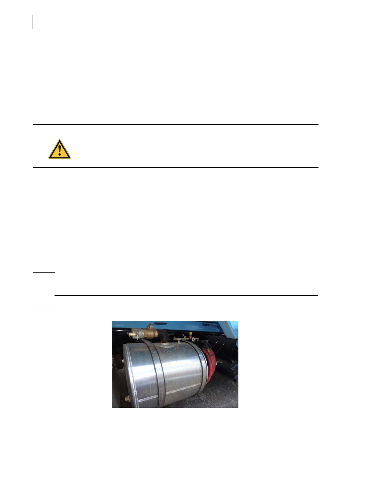
88 Operating the WITTKE PENDULUM™
Preparing the Unit Before Departure
To prepare the WITTKE PENDULUM™ for the clean-up process, proceed this way:
1. Open the tailgate until it is approximately 4 ft (1.2 m) from the tailgate seal.
2. Set the tailgate safety prop (see Tailgate Safety Prop on page 28).
3. Complete the lockout/tagout procedure (see Locking Out and Tagging Out the Vehicle on
page 36).
4. Clean the tailgate seal area of debris.
Warning!
5. Reverse the lockout/tagout procedure.
6. Remove the tailgate safety prop (see Tailgate Safety Prop on page 28).
7. Close the tailgate completely (see Tailgate Down Switch on page 60).
8. Reinstall both tailgate safety pins.
9. Retract the pendulum packer to its “home” position.
10. Raise the arms and forks to their “home” position.
11. Turn off the hydraulic pump (see Pump Switch on page 58).
Always use the tailgate safety prop while working under a raised tailgate. The safety prop
should be used even if the tailgate is in fully raised position.
Clean-Up Procedure
NOTE: Some trucks may be equipped with a wash-out tank with hose and nozzle (optional)
[see Figure 4-7].
Figure 4-7
Wash-out tank
Page 99

Operating the WITTKE PENDULUM™ 89
Warning!
Make sure the WITTKE PENDULUM™ is in an area where there is enough clearance to perform
cleaning and maintenance.
To clean up a WITTKE PENDULUM™ unit, do the following:
1. Drive to an appropriate clean-out area.
2. Set the parking brake.
3. Press the Pack button on the control panel (see Figure 3-26).
4. Press the Stop button (see Figure 3-25) to stop the packer at the end of its packing stroke.
5. Open the top door (see Top Door Switches (Roof Open/Roof Close) on page 64) to have a better
visibility of the hopper area.
6. Turn off the hydraulic pump.
The hydraulic pump switch should be blue-lighted (see Figure 3-16).
7. Complete the lockout/tagout procedure (see Locking Out and Tagging Out the Vehicle on
page 36).
8. Enter the hopper through the top of the hopper.
NOTE: Pressurized water can be used if necessary.
9. Inspect the condition of the hopper area and record any problems or concerns in a vehicle
condition report.
10. Once the cleaning is done, exit the hopper.
11. Reverse the lockout/tagout procedure (see Locking Out and Tagging Out the Vehicle on page 36).
Canopy Sweeper (optional)
Fixed to the fork torque tube and made of rubber, the optional canopy sweeper (see Figure 4-8) is
used to remove debris that may fall onto the canopy from a container on its way up. The debris that
remains on the canopy can be swept by a second lifting of the arms after the empty container has been
put back on the ground and released. The forks must be fully retracted in order to sweep the canopy
properly.
Page 100
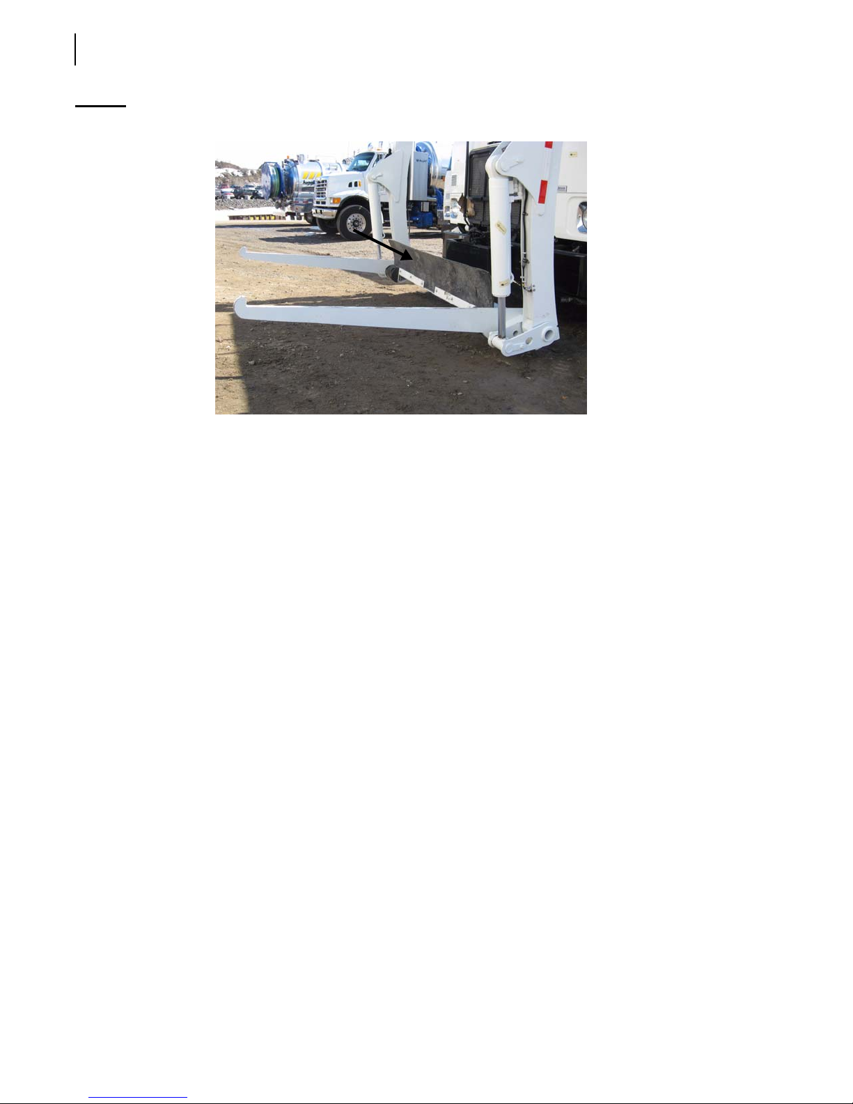
90 Operating the WITTKE PENDULUM™
Figure 4-8
Canopy sweeper
Shut-Down Procedure
To shut down your WITTKE PENDULUM™ unit, do the following:
1. Park the vehicle on solid, level ground.
2. Set the parking brake.
3. Ensure all hydraulic cylinders are collapsed (arms and forks up, tailgate closed, top door closed,
pendulum packer at “home” position).
4. Turn off the optional auto-neutral feature, if you were using the right-hand side driving position.
5. Turn off the hydraulic pump.
The pump switch on the control panel will turn blue, indicating that the hydraulic system is
disabled.
6. Turn off all lights (work lights, strobe light, etc.).
7. Shut the unit off following the chassis manufacturer’s recommendations.
8. Drain air from all air tanks.
9. Turn off the master switch (see Figure 4-9).
 Loading...