

Page 1
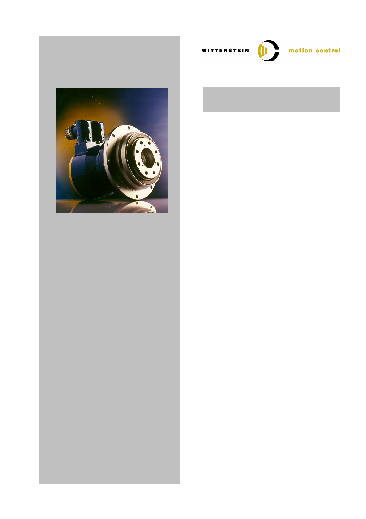
TPM(A)
004 – 110
SEIDEL
SERVOSTAR 600
Quick Startup Guide
Version : 1.1
Date : 07. September 2006
File : 4091_D006391_02.doc
Doc.No. : 4091-D006391-02
Technical changes reserved!
Page 2

Quick Startup Guide Seidel Servostar 600
Table of Contents
TABLE OF CONTENTS .......................................................................................................................... 2
1 GENERAL INFORMATION AND SAFETY INSTRUCTIONS ........................................................ 3
2 NAME PLATE DATA DETAILS ...................................................................................................... 4
3 PARAMETER LIST TPM ⇔⇔⇔⇔ SERVOSTAR 600 ............................................................................. 5
3.1 S
ELECTION OF THE MOTOR FEEDBACK AND ENCODER OFFSET
3.2 TPM
3.3 TPM
3.4 TPMA
3.5 TPMA
WITH
WITH
WITH
WITH
320 V DC600 V DC-
320 V DC600 V DC-
BUS
........................................................................................................... 6
BUS
........................................................................................................... 7
BUS
......................................................................................................... 8
BUS
......................................................................................................... 9
........................................................ 5
4 CONNECTION SCHEMATIC TPM ⇔⇔⇔⇔ SERVOSTAR 600 ............................................................ 10
4.1 TPM
4.2 TPM
4.3 TPM
WITH RESOLVER-FEEDBACK
WITH ABSOLUTE ROTARY ENCODER HEIDENHAIN
WITH ABSOLUTE ROTARY ENCODER STEGMANN
.............................................................................................. 10
ECN 1313 / EQN 1325 ............................ 10
SRS / SRM 050......................................... 11
5 ASSIGNMENT TPM ⇔⇔⇔⇔ SERVO AMPLIFIER ⇔⇔⇔⇔ CABLE SET ..................................................... 12
5.1 TPM
5.2 TPM
5.3 TPM
WITH RESOLVER-FEEDBACK
WITH ABSOLUTE ROTARY ENCODER HEIDENHAIN
WITH ABSOLUTE ROTARY ENCODER STEGMANN
.............................................................................................. 12
ECN 1313 / EQN 1325 ............................ 13
SRS 050 / SRM 050.................................. 14
Modification History
Document Designation Version Date Note
4091_D006391_1.doc 1.0 06.06.2003 First edition
4091_D006391_02.doc 1.1 07.09.2006 TPM004, TPMA added
Contact address:
WITTENSTEIN motion control GmbH
Walter-Wittenstein-Strasse 1
97 999 Igersheim
Tel. : 07931 / 493-0
Fax : 07931 / 493-200
Email :
Document-No.: 4091-D006391-02 Date: 07. September 2006 Page 2 of 14
Page 3

Quick Startup Guide Seidel Servostar 600
1 General Information and Safety Instructions
This guide serves as an aid during start-up and inspection of TPM motor gear units with servo amplifiers. It contains the following points:
•
Parameter lists for the TPM series
•
Connection schematic for TPM
•
Assignment table TPM – Servo amplifier - cable set
Please be sure to carefully read through this document before starting up the TPM and also be
sure to read the documentation provided by the manufacturer of the servo amplifier.
WITTENSTEIN motion control will not be held liable for the consequences of the improper, negligent, or incorrect installation or setting of the servo amplifier's operating
parameters.
All of the installation, operation, and safety information provided in the servo amplifier
documentation is to be observed.
Observe all of the national safety regulations and guidelines of the country where the device is being used.
All transportation, installation, start-up, and service work is to be performed by qualified technicians. Qualified technicians are those who are completely familiar with the assembly, installation, and operating procedures, as well as all warnings and safety measures in accordance with the country-specific regulations. Furthermore, they are trained, instructed, and authorised to set the electrical circuits and other devices into operation in accordance with safety regulations.
The drives are intended to be installed in machines being used in commercial applications. You may only
operate the equipment if you comply to the national EMC regulations (refer to the servo amplifier documentation for installation information pertaining to EMC) as they are defined for the given application.
Note: All of the product brand names which appear in this Quick Start Guide are trademarks of the relevant
companies. If the ® and/or ™ symbols are omitted, this does imply that the name is a free brand name.
Document-No.: 4091-D006391-02 Date: 07. September 2006 Page 3 of 14
Page 4
Quick Startup Guide Seidel Servostar 600
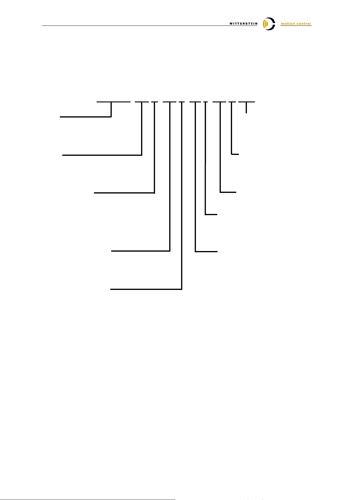
2 Name plate data details
Please select the input parameters corresponding to the nameplate values of your TPM.
TPM 010–091 M–600 K–BP 1–015 IF STD
Size
TPM 004 / 010 / 025 / 050 / 110
TPMA 025 / 050 / 110
Ratio
21 / 31 / 61 / 91 (TPM)
110 / 154 / 220 (TPMA)
Motor encoder
R = Resolver
S = Singleturn Heidenhain EnDat®
M = Multiturn Heidenhain EnDat®
N = Singleturn Stegmann Hiperface®
K = Multiturn Stegmann Hiperface®
I = Heidenhain incremental encoder
Intermediate voltage
320
600
Temperature sensor
P = PTC STM 160 in accordance with
DIN 44081 / 44082
N = NTC
K = KTY 84-130
Plug form
STD = angle
SEG = straight
XXX = custom
Standard
IF = industry standard
UL = UL recognised
file E220160
Stator length
Clearance specification
1 = Standard < 3 arcmin
(TPM 004: < 5 arcmin)
0 = Reduced < 1 arcmin
(TPM 004: < 3 arcmin)
Brake
BP = Permanent magnetic
brake
OH = Without brake
Document-No.: 4091-D006391-02 Date: 07. September 2006 Page 4 of 14
Page 5

Quick Startup Guide Seidel Servostar 600
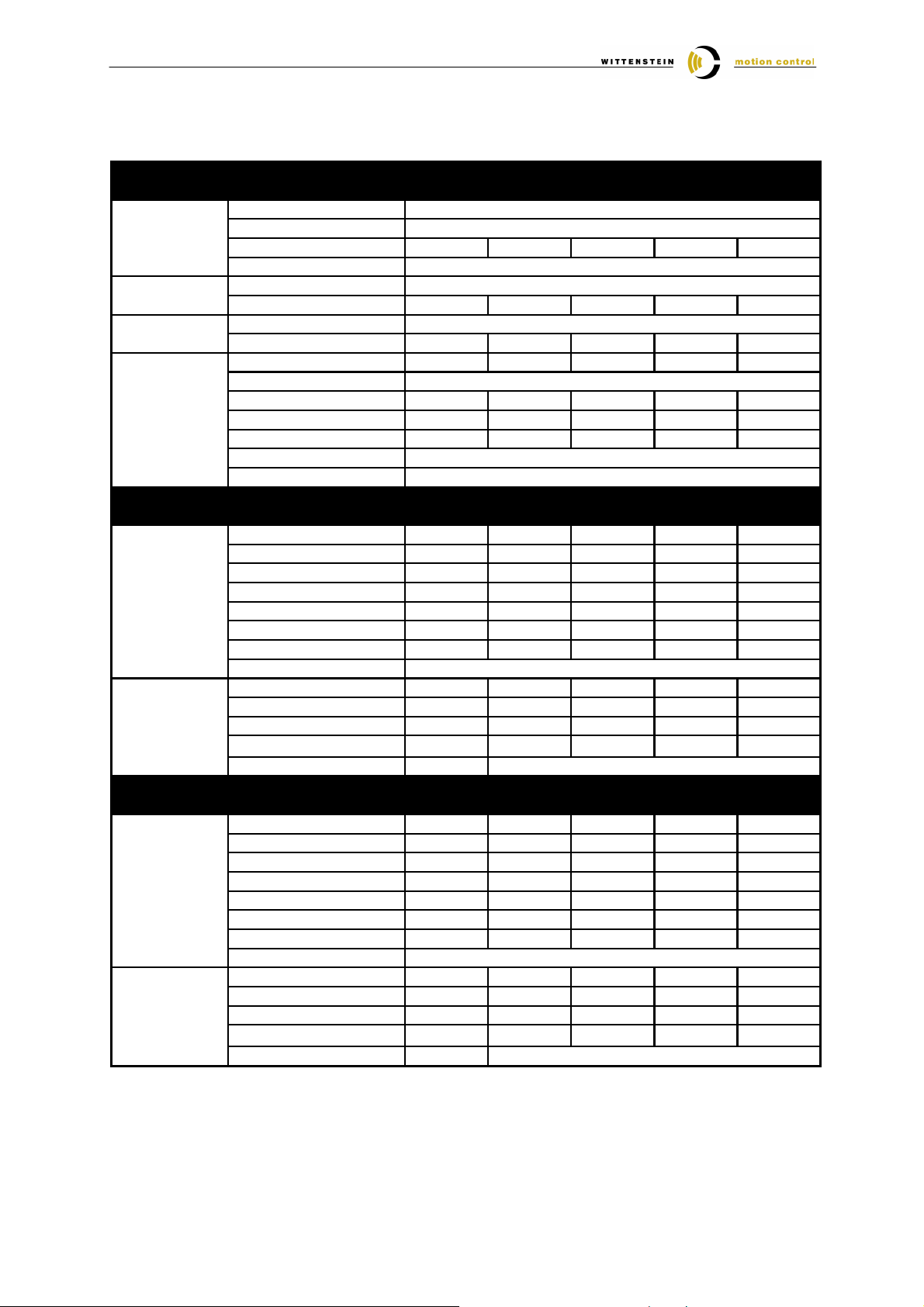
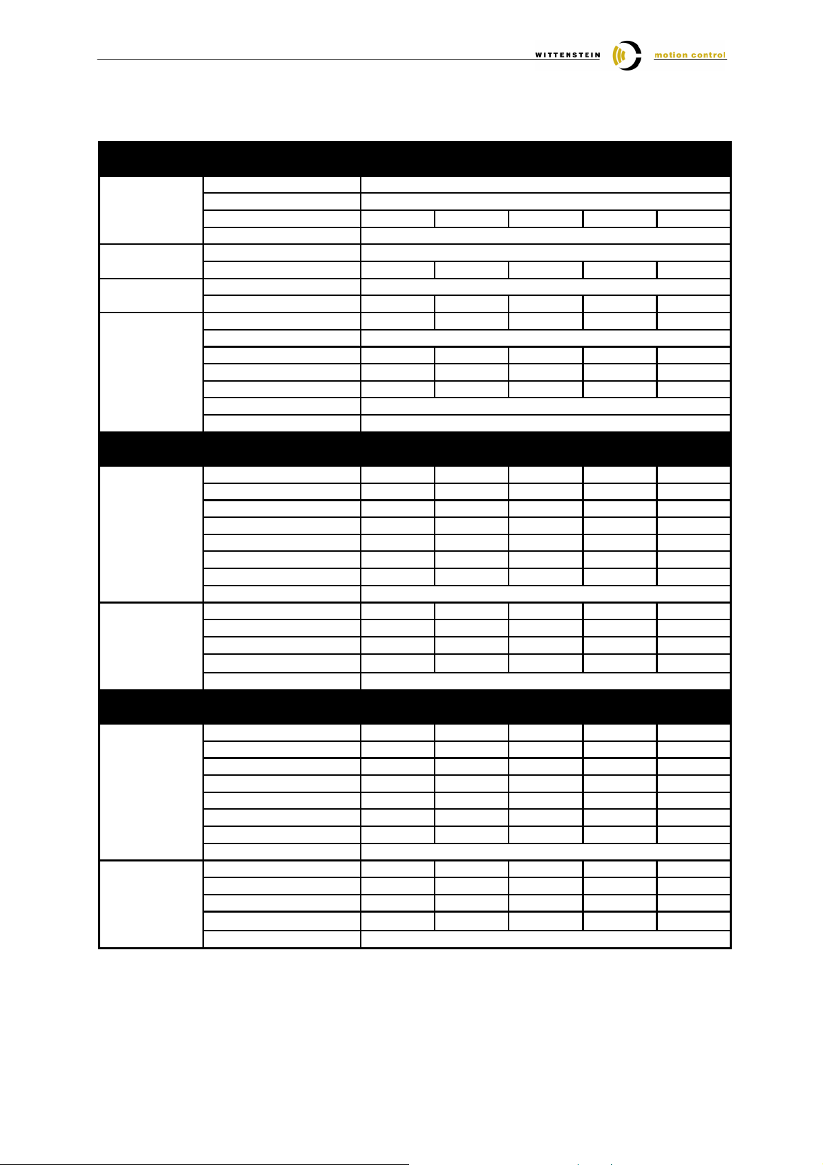
3 Parameter list TPM / TPMA ⇔⇔⇔⇔ Servostar 600
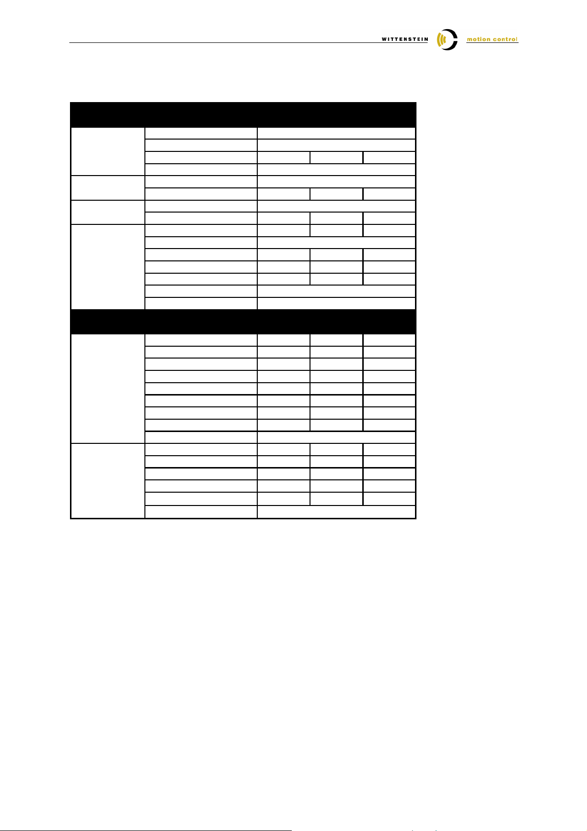
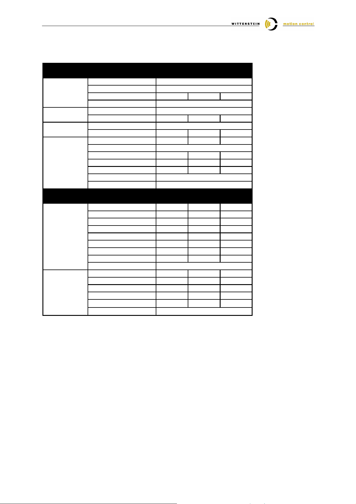
The following table contains all of the parameters that are required for the initial start-up of a TPM motorgear unit from WITTENSTEIN motion control together with a Seidel Servostar 600. When the TPM and the
servo amplifier are properly connected, these parameters guarantee that the TPM can be operated without
load in speed control. Based on these default settings, the dynamics of the speed loop can be optimized depending on the application.
3.1 Selection of the motor feedback and encoder offset
For the selection of the motor feedback and the encoder offset the following inputs must be done:
1. Open the screen Terminal in the Drive software
2. Depending on the motor feedback enter the following commands:
Resolver: MRESPOLES 2
FBTYPE 0
Heidenhain EnDat: FBTYPE 4
Stegmann Hiperface: FBTYPE 2
After input of FBTYPE <WERT>, please confirm the message „Save to EEPROM and reset?“ with „YES“
3. After the restart open the Screen Terminal and enter the encoder offset with the command MPHASE <OFFSET>
Instead of <OFFSET> enter he appropriate value of the following parameter list
4. For TPM with Resolver you must save the offset in the amplifier with the input of the command SAVE
For TPM with EnDat you must store the offset to the encoder with the command HSAVE
For TPM with Hiperface you must store the offset to the encoder with the two commands HSAVE ERASE and
HSAVE
5. Restart the amplifier with the input of COLDSTART
Document-No.: 4091-D006391-02 Date: 07. September 2006 Page 5 of 14
Page 6
Quick Startup Guide Seidel Servostar 600
Screen Page
Parameter
TPM004
TPM010
TPM025
TPM050
TPM110
1
1
Tn [ms]
0.4
3.2 TPM with 320 V DC-bus
DC-Bus Voltage
Feedback Feedback Type
No. of Poles
320 V
Resolver
2
Offset 90 90 270 270 270
Bandwith
Feedback Type
600
EnDat
Offset 90 90 90 90 90
Feedback Type
HIPERFACE
Offset 150 150 150 150 150
Speed Speed Limit [rpm] 7000 7000 6000 5000 4500
Rotary Direction
Positive
Overspeed [rpm] 7250 7250 6250 5250 4750
Kp 0.3 0.3 0.3 0.4 0.5
Tn [ms] 10 10 10 10 10
PID-T2
T-Tacho
0.2
0.6
Ratio 21 / 31
Stator Length 030 030 045 060 075
Motor Number - Name 0-NN 0-NN 0-NN 0-NN 0-NN
No. of Poles 8 8 12 12 12
I0 [Arms] 1.5 1.7 8.7 23.9 18.0
I0max @ i = 21 [Arms] 4.2 7.3 24.2 42.0 42.0
I0max @ i = 31 [Arms] 3.7 5.7 19.7 42.0 42.0
L [mH] 10.2 12.2 2.5 1.0 2.4
Max Speed [rpm] 7000 7000 6000 5000 4500
Holding Brake
with / without
Current Irms [Arms] 1.5 1.7 8.7 23.9 18.0
Ipeak @ i = 21 [Arms] 4.2 7.3 24.2 42.0 42.0
Ipeak @ i = 31 [Arms] 3.7 5.7 19.7 42.0 42.0
Kp
Tn [ms] 0.4
0.77 0.92 0.88 0.35 1.20
0.6
Ratio 61 / 91
Stator Length 015 015 015 015 060
Motor Number - Name 0-NN 0-NN 0-NN 0-NN 0-NN
No. of Poles 8 8 12 12 12
I0 [Arms] 1.2 1.2 3.7 5.2 23.9
I0max @ i = 61 [Arms] 2.5 3.5 12.9 22.2 42.0
I0max @ i = 91 [Arms] 1.7 2.4 8.7 14.9 32.1
L [mH] 9.1 13.1 5.2 6.1 1.0
Max Speed [rpm] 7000 7000 6000 5000 4500
Holding Brake
with / without
Current Irms [Arms] 1.2 1.2 3.7 5.2 23.9
Ipeak @ i = 61 [Arms] 2.5 3.5 12.9 22.2 42.0
Ipeak @ i = 91 [Arms] 1.7 2.4 8.7 14.9 32.1
Kp
0.34 0.49 0.78 1.53 0.50
0.6
1
The value Kp of the current controller is acquired in addiction of the recommended WMC amplifier size.
You find the recommended amplifier size under the topic „Assignment TPM – servo amplifier – cable set“.
For the usage of a different amplifier size you can calculate the value with the formula:
Kp = 25 * Nominal current amplifier [A] * Inductance [mH] / 1000
Document-No.: 4091-D006391-02 Date: 07. September 2006 Page 6 of 14
Page 7
Quick Startup Guide Seidel Servostar 600
Screen Page
Parameter
TPM004
TPM010
TPM025
TPM050
TPM110
1
1
Tn [ms]
3.3 TPM with 600 V DC-bus
DC-Bus Voltage
Feedback Feedback Type
No. of Poles
600 V
Resolver
2
Offset 90 90 270 270 270
Bandwith
Feedback Type
600
EnDat
Offset 90 90 90 90 90
Feedback Type
HIPERFACE
Offset 150 150 150 150 150
Speed Speed Limit [rpm] 7000 7000 6000 5000 4500
Rotary Direction
Positive
Overspeed [rpm] 7250 7250 6250 5250 4750
Kp 0.2 0.3 0.3 0.4 0.5
Tn [ms] 10 10 10 10 10
PID-T2
T-Tacho
0.2
0.6
Ratio 21 / 31
Stator Length 030 030 045 060 075
Motor Number - Name 0-NN 0-NN 0-NN 0-NN 0-NN
No. of Poles 8 8 12 12 12
I0 [Arms] 0.8 1.3 4.4 15.3 12.1
I0max @ i = 21 [Arms] 2.4 5.0 10.6 36.0 26.2
I0max @ i = 31 [Arms] 2.1 4.5 10.6 31.7 26.2
L [mH] 30.6 20.3 10.0 2.4 5.4
Max Speed [rpm] 7000 7000 6000 5000 4500
Holding Brake
with / without
Current Irms [Arms] 0.8 1.3 4.4 15.3 12.1
Ipeak @ i = 21 [Arms] 2.4 5.0 10.6 36.0 26.2
Ipeak @ i = 31 [Arms] 2.1 4.5 10.6 31.7 26.2
Kp
Tn [ms]
1.15 1.52 1.50 0.84 1.89
0.6
Ratio 61 / 91
Stator Length 015 015 015 015 060
Motor Number - Name 0-NN 0-NN 0-NN 0-NN 0-NN
No. of Poles 8 8 12 12 12
I0 [Arms] 0.6 0.8 2.3 3.6 15.3
I0max @ i = 61 [Arms] 1.2 2.5 7.0 13.7 28.9
I0max @ i = 91 [Arms] 0.8 1.6 5.1 9.9 19.4
L [mH] 27.6 30.5 12.5 12.5 2.4
Max Speed [rpm] 7000 7000 6000 5000 4500
Holding Brake
with / without
Current Irms [Arms] 0.6 0.8 2.3 3.6 15.3
Ipeak @ i = 61 [Arms] 1.2 2.5 7.0 13.7 28.9
Ipeak @ i = 91 [Arms] 0.8 1.6 5.1 9.9 19.4
Kp
1.04 1.14 0.94 1.88 0.60
0.6
1
The value Kp of the current controller is acquired in addiction of the recommended WMC amplifier size.
You find the recommended amplifier size under the topic „Assignment TPM – servo amplifier – cable set“.
For the usage of a different amplifier size you can calculate the value with the formula:
Kp = 25 * Nominal current amplifier [A] * Inductance [mH] / 1000
Document-No.: 4091-D006391-02 Date: 07. September 2006 Page 7 of 14
Page 8
Quick Startup Guide Seidel Servostar 600
Screen Page
Parameter
TPMA025
TPMA050
TPMA110
1
Tn [ms]
3.4 TPMA with 320 V DC-bus
DC-Bus Voltage
Feedback Feedback Type
No. of Poles
320
Resolver
2
Offset 270 270 270
Bandwith
Feedback Type
600
EnDat
Offset 90 90 90
Feedback Type
HIPERFACE
Offset 150 150 150
Speed Speed Limit [rpm] 6000 5000 4500
Rotary Direction
Positive
Overspeed [rpm] 6250 5250 4750
Kp 0.3 0.4 0.5
Tn [ms] 10 10 10
PID-T2
T-Tacho
0.2
0.6
Ratio 110 / 154 / 220
Stator Length 015 015 060
Motor Number - Name 0-NN 0-NN 0-NN
No. of Poles 12 12 12
I0 [Arms] 3.7 5.2 23.9
I0max @ i = 110 [Aeff] 10.8 19.6 61.6
I0max @ i = 154 [Aeff] 8.4 16.0 42.6
I0max @ i = 220 [Aeff] 5.7 9.8 28.3
L [mH] 5.2 6.1 1.0
Max Speed [rpm] 6000 5000 4500
Holding Brake
with / without
Current Irms [Arms] 3.7 5.2 23.9
Ipeak @ i = 110 [Aeff] 10.8 19.6 61.6
Ipeak @ i = 154 [Aeff] 8.4 16.0 42.6
Ipeak @ i = 220 [Aeff] 5.7 9.8 28.3
Kp
0.78 1.53 0.50
0.6
1
The value Kp of the current controller is acquired in addiction of the recommended WMC amplifier size.
You find the recommended amplifier size under the topic „Assignment TPM – servo amplifier – cable set“.
For the usage of a different amplifier size you can calculate the value with the formula:
Kp = 25 * Nominal current amplifier [A] * Inductance [mH] / 1000
Document-No.: 4091-D006391-02 Date: 07. September 2006 Page 8 of 14
Page 9
Quick Startup Guide Seidel Servostar 600
Screen Page
Parameter
TPMA025
TPMA050
TPMA110
1
Tn [ms]
3.5 TPMA with 600 V DC-bus
DC-Bus Voltage
Feedback Feedback Type
No. of Poles
600 V
Resolver
2
Offset 270 270 270
Bandwith
Feedback Type
600
EnDat
Offset 90 90 90
Feedback Type
HIPERFACE
Offset 150 150 150
Speed Speed Limit [rpm] 6000 5000 4500
Rotary Direction
Positive
Overspeed [rpm] 6250 5250 4750
Kp 0.3 0.4 0.5
Tn [ms] 10 10 10
PID-T2
T-Tacho
0.2
0.6
Ratio 110 / 154 / 220
Stator Length 015 015 060
Motor Number - Name 0-NN 0-NN 0-NN
No. of Poles 12 12 12
I0 [Arms] 2.3 3.6 15.3
I0max @ i = 110 [Aeff] 7.0 13.7 41.4
I0max @ i = 154 [Aeff] 5.4 11.2 28.7
I0max @ i = 220 [Aeff] 3.6 7.0 19.2
L [mH] 12.5 12.5 2.4
Max Speed [rpm] 6000 5000 4500
Holding Brake
with / without
Current Irms [Arms] 2.3 3.6 15.3
Ipeak @ i = 110 [Aeff] 7.0 13.7 41.4
Ipeak @ i = 154 [Aeff] 5.4 11.2 28.7
Ipeak @ i = 220 [Aeff] 3.6 7.0 19.2
Kp
0.94 1.88 0.60
0.6
1
The value Kp of the current controller is acquired in addiction of the recommended WMC amplifier size.
You find the recommended amplifier size under the topic „Assignment TPM – servo amplifier – cable set“.
For the usage of a different amplifier size you can calculate the value with the formula:
Kp = 25 * Nominal current amplifier [A] * Inductance [mH] / 1000
Document-No.: 4091-D006391-02 Date: 07. September 2006 Page 9 of 14
Page 10
Quick Startup Guide Seidel Servostar 600
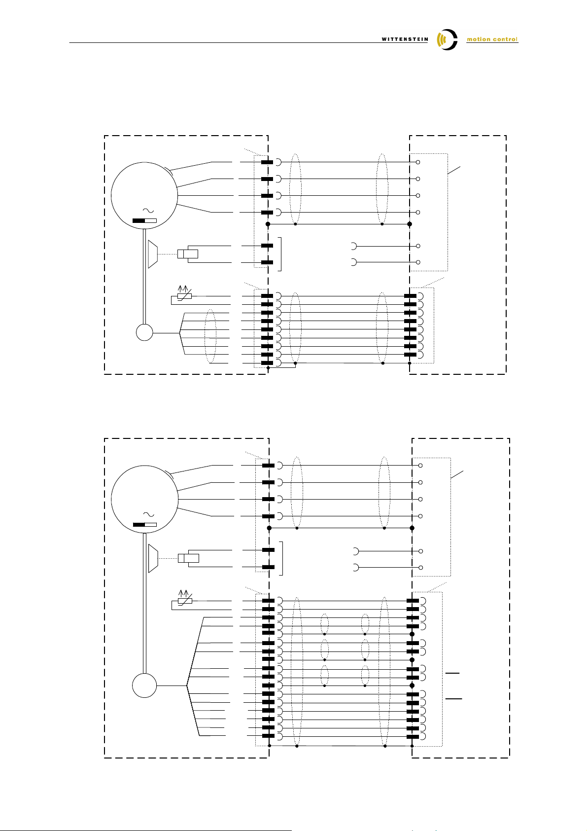
4 Connection schematic TPM ⇔⇔⇔⇔ Servostar 600
4.1 TPM with Resolver-Feedback
Power Plug
3
PE
4
U
5
V
6
W
Power
Terminal
Block
(X9)
M
3
PE
PE
2
U
4
V
1
W
Seidel
Br +
5
6
Br -
Brake optional
2
1
Signal Plug
5
PTC
6
PTC
7
Ref +
8
Ref -
3
R
Sin +
Sin -
Cos +
Cos -
Shield
4
1
2
9
Br+
Br-
2
Temp
6
Temp
5
+ Reference
9
- Reference
3
+ SIN
7
- SIN
8
+ COS
4
- COS
Servostar
Resolver Plug
(X2)
4.2 TPM with absolute rotary encoder Heidenhain ECN 1313 / EQN 1325
M
3
SC
Power Plug
Signal Plug
Data +
Data -
Takt +
Takt -
P-Encoder
5V Sense
M-Encoder
0V Sense
PE
Br +
Br -
KTY
KTY
A+
A-
B+
B-
PE
1
U
2
V
6
W
3
PE
4
U
5
V
6
W
Power
Terminal
Block
(X9)
Seidel
4
5
8
9
1
2
17
11
12
17
3
13
17
5
14
10
16
7
15
Brake optional
2
1
Br+
Br-
14
7
11
3
9
1
5
13
8
15
4
12
2
10
Servostar
Encoder (X1)
+ Temp
- Temp
A +
A -
B +
B -
DATA
DATA
CLOCK
CLOCK
UP Supply
UP Sense
0 V VSupply
0 V Sense
Document-No.: 4091-D006391-02 Date: 07. September 2006 Page 10 of 14
Page 11
Quick Startup Guide Seidel Servostar 600
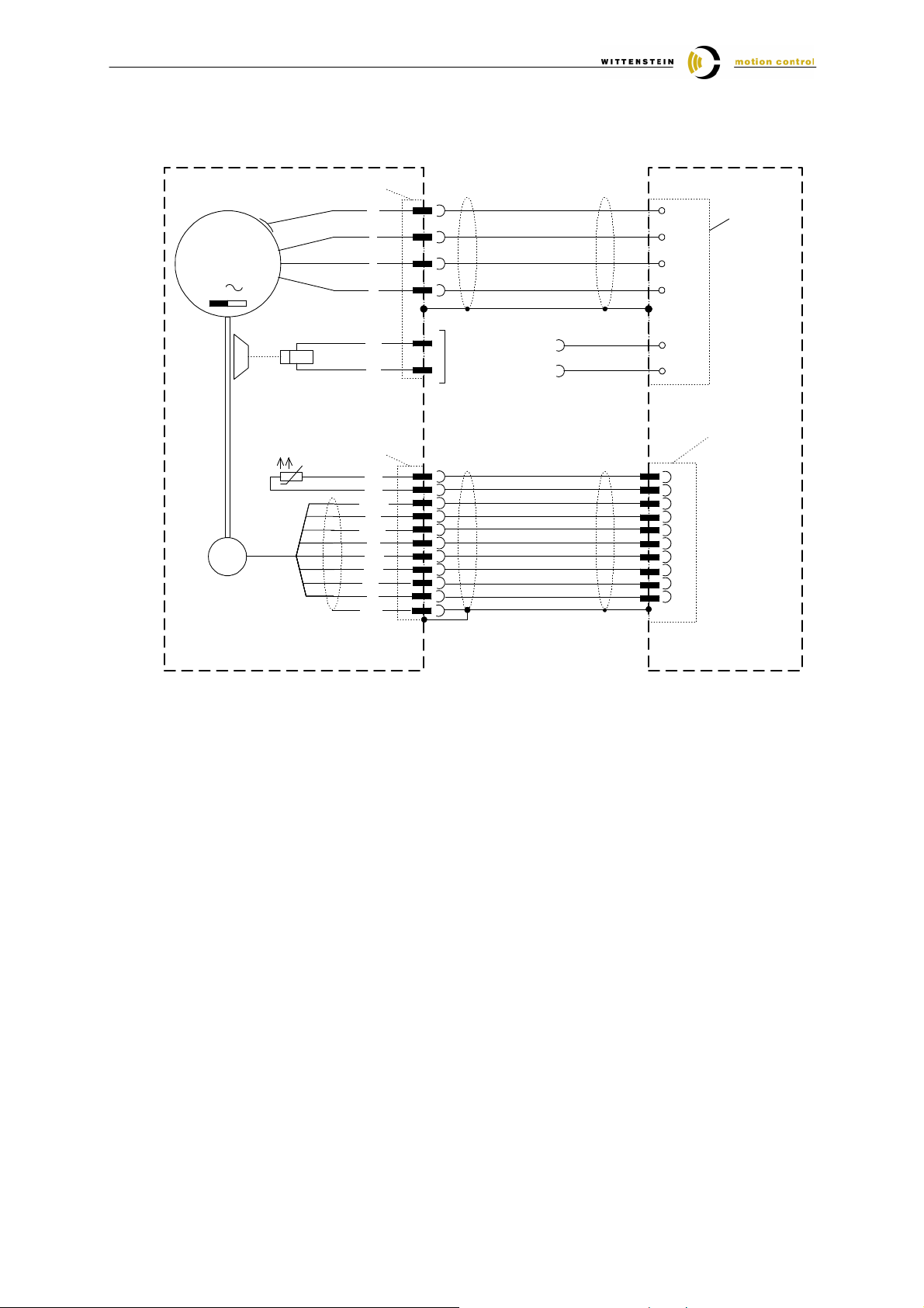
4.3 TPM with absolute rotary encoder Stegmann SRS / SRM 050
Power Plug
3
PE
4
U
5
V
6
W
2
Br+
1
Br-
14
7
11
3
9
1
13
5
2
4
M
3
SC
Signal Plug
Ref Cos
Ref Sin
+485
Gnd
Shield
PE
U
V
W
Br +
Br -
PTC
PTC
Cos
Sin
- 485
8V
PE
1
2
6
4
5
3
4
1
8
6
5
7
2
10
12
9
Brake optional
Power
Terminal
Block
(X9)
Seidel
Servostar
Encoder (X1)
Temp
Temp
REFCOS
+ COS
REFSIN
+ SIN
RS485
RS485
GND
Us
Document-No.: 4091-D006391-02 Date: 07. September 2006 Page 11 of 14
Page 12
Quick Startup Guide Seidel Servostar 600
5 Assignment TPM ⇔⇔⇔⇔ servo amplifier ⇔⇔⇔⇔ cable set
5.1 TPM with Resolver-Feedback
TPM type Controller Code of power- (L) and signal cable (S)
Feed-
back
Size i
021 Servostar 603 Servostar 601
031
TPM 004 061 Servostar 601 Servostar 601
TPM 010 061 Servostar 601 Servostar 601
TPM 025 061 Servostar 606 Servostar 603
Resolver
TPM 050 061 Servostar 610 Servostar 606
TPM 110 061 Servostar 620 Servostar 614
091 Servostar 601 Servostar 601
021 Servostar 603 Servostar 603
031 Servostar 603 Servostar 603
091 Servostar 601 Servostar 601
021 Servostar 614 Servostar 606
031 Servostar 610 Servostar 606
091 Servostar 603 Servostar 603
021 Servostar 614 Servostar 614
031 Servostar 614 Servostar 614
091 Servostar 606 Servostar 603
021 Servostar 620 Servostar 614
031 Servostar 620 Servostar 614
091 Servostar 614 Servostar 610
WMC recommendation
320V 600V L S L S L S L S L S L S L S L S
Servostar 603 Servostar 601
1
5m 10m 15m 20m 25m 30m
4000 3876
4000 6328
4000 3877
4000 6440
4000 6456
4000 6329
40m 50m
4000 3878
4000 6330
4000 3879
4000 6505
4000 6331
4000 6169
4000 6602
4000 7688
4000 6093
4000 7659
4000 7689
4000 7678
4000 7660
4000 7690
4000 7452
4000 7661
4000 7662
4000 7691
1
WMC recommendation is based on use of a power stage with maximal PWM-frequency. Please refer to WMC or controller manufactor to select optimized controller size for the application.
Possibly you are able to use a smaller controller.
Power and signal cable to connect on motors with resolver
All cable complete and for dynamic laying
Power cable TPM 004-050
Power cable TPM 110
Signal cable
Document-No.: 4091-D006391-02 Date: 07. September 2006 Page 12 of 14
KABELL-TPM_-xxSTD_-RES015-STG
KABELL-TPM_-xxSTD_-RES025-STG
KABELS-TPM_-xxSEI_-RES000-STG
(xx = cable length)
Design power cable:
Design power cable:
Design signal cable:
4 x 1,5mm2 + 2 x (2 x 1mm2), diameter 12,2mm, min. bending radius 122mm
4 x 2,5mm2 + 2 x (2 x 1mm2), diameter 15,1mm, min. bending radius 151mm
4 x (2 x 0,25mm2) + 2 x 1mm2, diameter 8,8mm; min. bending radius 88mm
Page 13
Quick Startup Guide Seidel Servostar 600
5.2 TPM with absolute rotary encoder Heidenhain ECN 1313 / EQN 1325
TPM type Controller Code of power- (L) and signal cable (S)
Feed-
back
Size i
021 Servostar 603 Servostar 601
031
TPM004 061 Servostar 601 Servostar 601
EnDat
TPM 010 061 Servostar 601 Servostar 601
TPM 025 061 Servostar 606 Servostar 603
single-/multiturn transmitter with
TPM 050 061 Servostar 610 Servostar 606
Absolute
TPM 110 061 Servostar 620 Servostar 614
091 Servostar 601 Servostar 601
021 Servostar 603 Servostar 603
031 Servostar 603 Servostar 603
091 Servostar 601 Servostar 601
021 Servostar 614 Servostar 606
031 Servostar 610 Servostar 606
091 Servostar 603 Servostar 603
021 Servostar 614 Servostar 614
031 Servostar 614 Servostar 614
091 Servostar 606 Servostar 603
021 Servostar 620 Servostar 614
031 Servostar 620 Servostar 614
091 Servostar 614 Servostar 610
WMC recommendation
320V 600V L S L S L S L S L S L S L S L S
Servostar 603 Servostar 601
1
5m 10m 15m
4000 5465
4000 6830
4000 5466
4000 8708
4000 8709
4000 6831
20m 25m 30m
4000 5467
4000 6832
4000 54684000 6833
4000 8710
40m 50m
4000 6054
4000 8711
4000 7692
4000 76794000 7693
4000 8712
4000 8713
4000 7694 4000 7328
4000 5920
4000 8714
4000 8715
4000 7695
1
WMC recommendation is based on use of a power stage with maximal PWM-frequency. Please refer to WMC or controller manufactor to select optimized controller size for the application.
Possibly you are able to use a smaller controller.
Power and signal cable to connect on motors with absolut EnDat feedback ECN1313 / EQN1325
All cable complete and for dynamic laying
Power cable TPM 004-050 KABELL-TPM_-xxSTD_-END015-STG
Power cable TPM 110 KABELL-TPM_-xxSTD_-END025-STG
Signal cable KABELS-TPM_-xxSEI_-END000-STG
(xx = cable length)
Document-No.: 4091-D006391-02 Date: 07. September 2006 Page 13 of 14
Design power cable:
Design power cable:
Design signal cable:
4 x 1,5mm2 + 2 x 1mm2, diameter 12mm, min. bending radius 120mm
4 x 2,5mm2 + 2 x 1mm2, diameter 15,1mm, min. bending radius 151mm
3 x (2 x 0,14mm2) + 4 x 0,14mm2 + 4 x 0,25mm2 + 2 x 0,5mm2; diameter 10mm
min. bending radius 100mm
Page 14
Quick Startup Guide Seidel Servostar 600
(xx = cable length)
5.3 TPM with absolute rotary encoder Stegmann SRS 050 / SRM 050
TPM type Controller Code of power- (L) and signal cable (S)
Feed-
back
Size i
021 Servostar 603 Servostar 601
031
TPM 004 061 Servostar 601 Servostar 601
HIPERFACE
TPM 010 061 Servostar 601 Servostar 601
TPM 025 061 Servostar 606 Servostar 603
TPM 050 061 Servostar 610 Servostar 606
single-/multiturn transmitter with
TPM 110 061 Servostar 620 Servostar 614
Absolute
091 Servostar 601 Servostar 601
021 Servostar 603 Servostar 603
031 Servostar 603 Servostar 603
091 Servostar 601 Servostar 601
021 Servostar 614 Servostar 606
031 Servostar 610 Servostar 606
091 Servostar 603 Servostar 603
021 Servostar 614 Servostar 614
031 Servostar 614 Servostar 614
091 Servostar 606 Servostar 603
021 Servostar 620 Servostar 614
031 Servostar 620 Servostar 614
091 Servostar 614 Servostar 610
WMC recommendation
320V 600V L S L S L S L S L S L S L S L S
Servostar 603 Servostar 601
1
5m 10m 15m 20m 25m 30m
4000 5465
4000 6830
4000 5466
4000 8723
4000 6831
4000 5467
4000 8724
4000 6832
40m 50m
4000 5468
4000 8725
4000 6833
4000 6054
4000 8726
4000 7692
4000 7679
4000 8727
4000 7693
4000 7328
4000 8728
4000 7694
4000 5920
4000 8729
4000 8730
4000 7695
1
WMC recommendation is based on use of a power stage with maximal PWM-frequency. Please refer to WMC or controller manufactor to select optimized controller size for the application.
Possibly you are able to use a smaller controller.
Power and signal cable to connect on motors with Stegmann HIPERFACE
All cable complete and for dynamic laying
Power cable TPM 004-050 KABELL-TPM_-xxSTD_-END015-STG
Power cable TPM 110 KABELL-TPM_-xxSTD_-END025-STG
Signal cable KABELS-TPM_-xxSEI_-HIP000-STG
Design power cable:
Design power cable:
Design signal cable:
4 x 1,5mm2 + 2 x 1mm2, diameter 12mm, min. bending radius 120mm
4 x 2,5mm2 + 2 x 1mm2, diameter 15,1mm, min. bending radius 151mm
4 x (2 x 0,25mm2) + 2 x 1mm2, diameter 8,8mm; min. bending radius 88mm
Document-No.: 4091-D006391-02 Date: 07. September 2006 Page 14 of 14
 Loading...