

Page 1
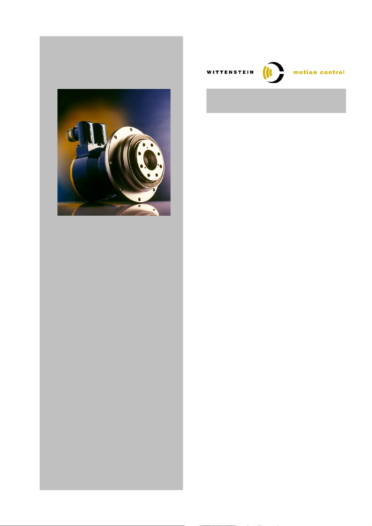
TPM(A)
004 – 110
Quick Startup Guide
BOSCH REXROTH
IndraDrive
Version : 1.1
Date : 19. October 2005
File : 4091_D010027_02.doc
Doc.No. : 4091-D010027-02
Technical changes reserved!
Page 2

Quick Startup Guide Bosch Rexroth IndraDrive
Table of Contents
TABLE OF CONTENTS.......................................................................................................................... 2
1 GENERAL INFORMATION AND SAFETY INSTRUCTIONS ........................................................ 3
2 NAME PLATE DATA DETAILS ...................................................................................................... 4
3 PARAMETERIZATION.................................................................................................................... 5
3.1 P
ARAMETER INPUT VIA SINGLE PARAMETER
3.1.1 Starting the dialog single parameter input ......................................................................... 5
3.1.2 Parameter input ................................................................................................................. 5
4 PARAMETERS TPM 600V RATIO 21/31 ....................................................................................... 6
5 PARAMETERS TPM 600V RATIO 61/91 ....................................................................................... 7
6 PARAMETERS TPMA 025 - 110 600V........................................................................................... 8
.................................................................................. 5
7 TEMPERATURE SENSOR MONITORING OF THE TPM.............................................................. 9
7.1 TPM
7.2 TPM
WITH
KTY 84-130 .............................................................................................................. 9
WITH
PTC STM160 ........................................................................................................... 9
8 CONNECTION SCHEMATIC TPM / TPMA ⇔⇔⇔⇔ INDRADRIVE ...................................................... 10
8.1 TPM / TPMA
8.2 TPM / TPMA
WITH RESOLVER FEEDBACK
WITH ABSOLUTE ROTARY ENCODER
.................................................................................. 10
ECN 1113 / EQN 1125 / ECN 1313 / EQN 1325
10
8.3 TPM / TPMA
WITH ABSOLUTE ROTARY ENCODER HIPERFACE
SRS50 / SRM50 ......................... 11
9 DIAGNOSTIC MESSAGES DURING INITIAL START-UP .......................................................... 12
10 ASSIGNMENT TPM / TPMA ⇔⇔⇔⇔ SERVO AMPLIFIER ⇔⇔⇔⇔ CABLE SET........................................ 13
10.1 TPM / TPMA
10.2 TPM / TPMA
10.3 TPM / TPMA
Modification History
Document Designation Version Date Note
4091_D010027_01.doc 1.0 28. April 2005 First Edition
4091_D010026_02.doc 1.1 19. October 2005 Correction Parameter S-0-0106 and S-0-0107
WITH RESOLVER FEEDBACK
WITH ABSOLUTE ENCODER
WITH ABSOLUTE ENCODER
......................................................................... 13
ECN 1113 / EQN 1125 / ECN 1313 / EQN 132514
SRS 50 / SRM 50.............................................. 15
for TPM004-025 and TPMA025
Contact address:
WITTENSTEIN motion control GmbH
Walter-Wittenstein-Straße 1
97 999 Igersheim
Document-No.: 4091-D010027-02 Date: 19. October 2005 Page 2 of 15
Page 3

Quick Startup Guide Bosch Rexroth IndraDrive
1 General Information and Safety Instructions
This guide serves as an aid during start-up and inspection of TPM motor gear units with servo
amplifiers. It contains the following points:
•
Start-Up information
•
Parameter lists for the TPM series
•
Connection schematic for TPM
•
Assignment table TPM – Servo amplifier - cable set
Please be sure to carefully read through this document before starting up the TPM and also be
sure to read the documentation provided by the manufacturer of the servo amplifier.
WITTENSTEIN motion control will not be held liable for the consequences of the
improper, negligent, or incorrect installation or setting of the servo amplifier's operating parameters.
All of the installation, operation, and safety information provided in the servo amplifier documentation is to be observed.
Observe all of the national safety regulations and guidelines of the country where the device is
being used. All transportation, installation, start-up, and service work is to be performed by
qualified technicians. Qualified technicians are those who are completely familiar with the assembly, installation, and operating procedures, as well as all warnings and safety measures in
accordance with the country-specific regulations. Furthermore, they are trained, instructed,
and authorised to set the electrical circuits and other devices into operation in accordance with
safety regulations.
The drives are intended to be installed in machines being used in commercial applications.
You may only operate the equipment if you comply to the national EMC regulations (refer to
the servo amplifier documentation for installation information pertaining to EMC) as they are
defined for the given application.
Note: All of the product brand names which appear in this Quick Start Guide are trademarks of
the relevant companies. If the ® and/or ™ symbols are omitted, this does not imply that the
name is a free brand name.
Document-No.: 4091-D010027-02 Date: 19. October 2005 Page 3 of 15
Page 4
Quick Startup Guide Bosch Rexroth IndraDrive
2 Name plate data details
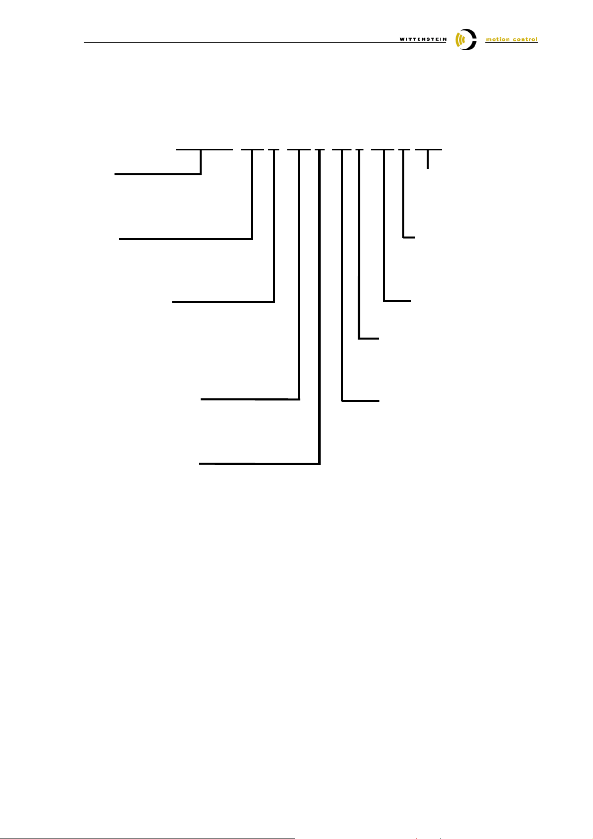
The following specifications can be found on the identification plate. Please select the input parameters
corresponding to the nameplate values of your drive.
TPM 010–091 M–600 K–BP 1–015 IF STD
Size
TPM 004 / 010 / 025 / 050 / 110
TPMA 025 / 050 / 110
Ratio
21 / 31 / 61 / 91 (TPM)
110 / 154 / 220 (TPMA)
R = Resolver
S = Singleturn Heidenhain EnDat®
M = Multiturn Heidenhain EnDat®
N = Singleturn Stegmann Hiperface®
K = Multiturn Stegmann Hiperface®
I = Heidenhain incremental encoder
Intermediate voltage
320
600
Plug form
STD = angle
SEG = straight
XXX = custom
Standard
IF = industry standard
UL = UL recognised
file E220160
Stator lengthMotor encoder
Clearance specification
1 = Standard < 3 arcmin
(TPM 004: < 5 arcmin)
0 = Reduced < 1 arcmin
(TPM 004: < 3 arcmin)
Brake
BP = Permanent magnetic
brake
OH = Without brake
Temperature sensor
P = PTC STM 160 in accordance with
DIN 44081 / 44082
N = NTC
K = KTY 84-130
Document-No.: 4091-D010027-02 Date: 19. October 2005 Page 4 of 15
Page 5
Quick Startup Guide Bosch Rexroth IndraDrive
3 Parameterization
To operate the TPM together with a drive of the IndraDrive-family the motor parameters need to be put
in.
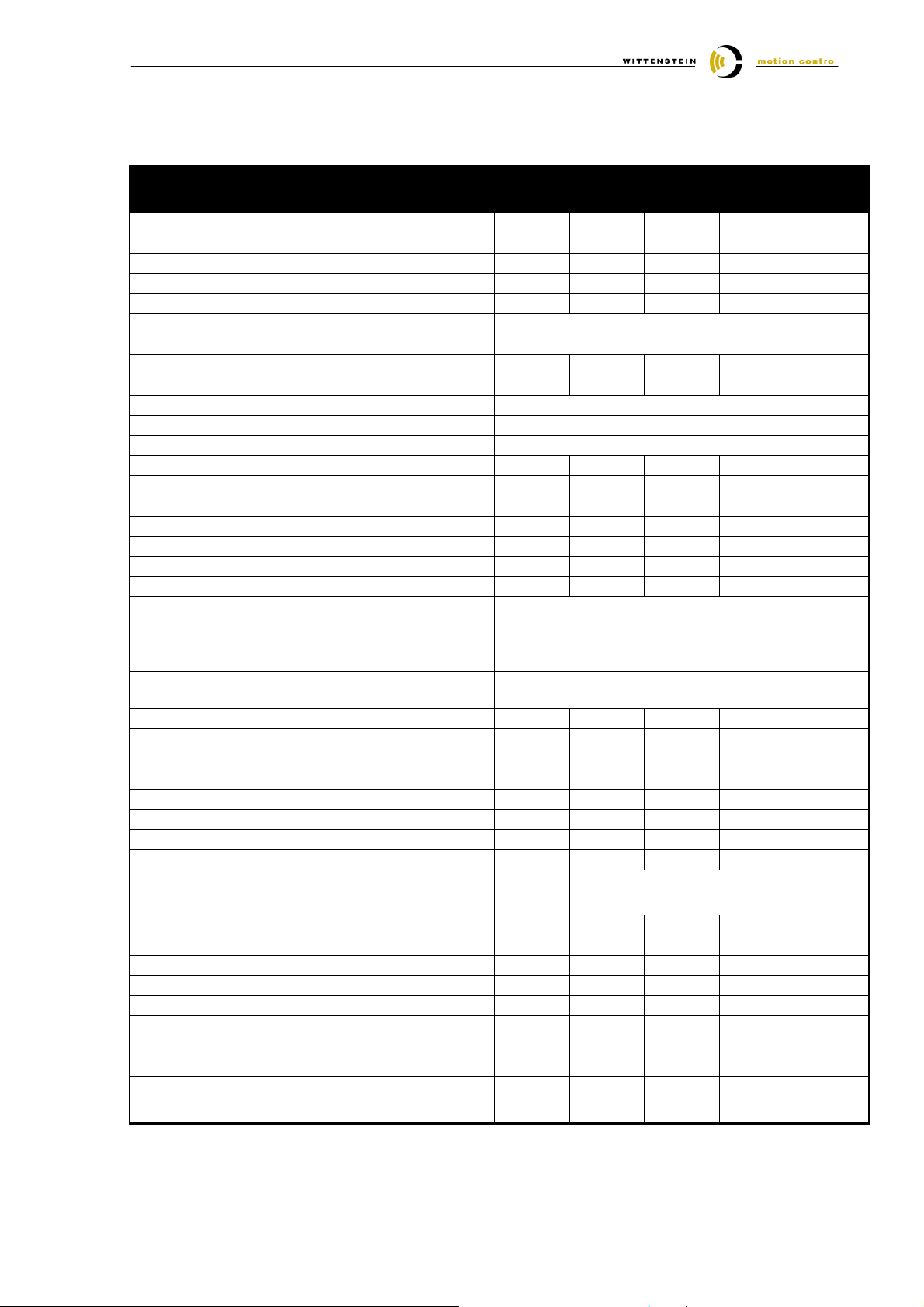
The tables in section 4, 5 and 6 contain all of the parameters that are required for the initial start-up of a
TPM motor-gear unit from WITTENSTEIN motion control together with a Bosch Rexroth IndraDrive.
When the TPM and the servo amplifier are properly connected, these parameters guarantee that the
TPM can be operated without load in speed control. Based on these default settings, the dynamics of
the speed loop can be optimized depending on the application.
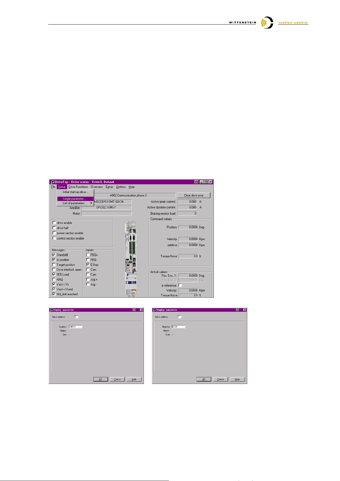
Together with the DriveTop-Software the data can be loaded via the single parameter dialog.
3.1 Parameter input via single parameter
With this option each parameter number and each parameter value needs to be put in. In this case it is
necessary to use the parameters from table in section 4, 5 or 6 depending on the TPM you use.
3.1.1 Starting the dialog single parameter input
3.1.2 Parameter input
Input of p4014 is sufficient for selecting Parameter P-0-4014, s109 for S-0-0109.
Document-No.: 4091-D010027-02 Date: 19. October 2005 Page 5 of 15
Page 6
Quick Startup Guide Bosch Rexroth IndraDrive
1
1
1
1
1
1
4 Parameters TPM 600V ratio 21/31
Data for combinations not shown here are available on demand.
Code Description TPM 004 TPM 010 TPM 025 TPM 050 TPM 110
Statorlength 30 30 45 60 75
S-0-0141
P-0-4014
P-0-0001
P-0-0018
P-0-0051
P-0-0074
P-0-0109
P-0-0508
P-0-0510
P-0-4016
P-0-4017
P-0-4048
S-0-0043
S-0-0055
S-0-0085
S-0-0092 Bipolar torque / force limit value
S-0-0106
S-0-0107
S-0-0109
S-0-0111
S-0-0113
S-0-0116
S-0-0201
S-0-0204
S-0-0100
S-0-0101
P-0-0004
P-0-0525
S-0-0206
S-0-0207
P-0-0540
Motor type
Type of motor
Switching frequency [kHz]
Number of pole pairs
Torque constant [Nm/Aeff]
Encoder type 1 (motor encoder)
Resolver / EnDat / Hiperface
Torque peak limit i = 21 [%]
Torque peak limit i = 31[%]
Commutation offset Resolver / EnDat
Commutation offset Hiperface
Rotor inertia
i = 21 without brake [kgm²]
i = 21 with brake [kgm²]
i = 31 without brake [kgm²]
i = 31 with brake [kgm²]
Direct-axis inductance of motor [mH]
Quadrature-axis inductance of motor [mH]
Stator resistance [Ohm]
Velocity polarity parameter
Resolver / EnDat / Hiperface
Position polarities
Resolver / EnDat / Hiperface
Torque polarity parameter
Resolver / EnDat / Hiperface
i = 21 [%]
Bipolar torque / force limit value
Current loop proportional gain 1 [V/A]
Current loop integral action time 1 [ms]
Motor peak current i = 21 [Aeff]
Motor peak current i = 31 [Aeff]
Motor current at standstill [Aeff]
Maximum motor speed [1/min]
Feedback 1 resolution
Resolver / EnDat / Hiperface
Motor warning temperature [°C]
Motor shutdown temperature [°C]
Velocity loop proportional gain [As/rad]
Velocity loop integral action time [ms]
Velocity loop smoothing time constant [µs]
Holding brake control word
Drive on delay time [ms]
Drive off delay time [ms]
Torque of holding brake [Nm]
i = 31 [%]
TPM004 TPM010 TPM025 TPM050 TPM110
0 0 0 0 0
8 8 8 8 8
4 4 6 6 6
0,67 0,83 1,16 0,91 1,51
10 / 8 / 4
302 385 241 273 217
258 385 203 238 217
512
341
0,000017 0,000041 0,000248 0,000946 0,001367
0,000023 0,000049 0,000257 0,000969 0,001542
0,000017 0,000040 0,000244 0,000935 0,001311
0,000023 0,000048 0,000253 0,000958 0,001486
15,3 10,2 5 1,2 2,7
15,3 10,2 5 1,2 2,7
47,40 19,30 3,80 0,36 0,72
0111 / 0000 / 0000
1111 / 0000 / 0000
0111 / 0000 / 0000
302 385 241 273 217
258 385 203 238 217
60 32 13,5 5,3 11,9
0,3 0,7 1,1 6,67 7,5
2,4 5 10,6 41,8 26,2
2,1 5 8,9 36,4 26,2
0,80 1,30 4,40 15,30 12,10
7000 7000 6000 5000 4300
1 / 512
1024 1 / 2048 / 1024
130 130 130 130 130
145 145 145 145 145
0.05 0.05 0.2 0.2 0.2
10 10 10 10 10
250 250 250 250 250
100
100
100
100
100
12 25 25 50 50
6 6 6 10 10
0,4
0,8
(Resolver)
1,8 1,8 15 15
1
In case of TPM without brake, the parameter P-0-0525 has to be set to 0.
Document-No.: 4091-D010027-02 Date: 19. October 2005 Page 6 of 15
Page 7
Quick Startup Guide Bosch Rexroth IndraDrive
2
2
2
2
2
2
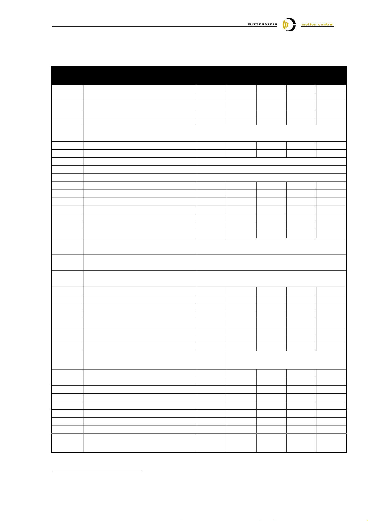
5 Parameters TPM 600V ratio 61/91
Data for combinations not shown here are available on demand.
Code Description TPM 004 TPM 010 TPM 025 TPM 050 TPM 110
Statorlength 15 15 15 15 60
S-0-0141
P-0-4014
P-0-0001
P-0-0018
P-0-0051
P-0-0074
P-0-0109
P-0-0508
P-0-0510
P-0-4016
P-0-4017
P-0-4048
S-0-0043
S-0-0055
S-0-0085
S-0-0092 Bipolar torque / force limit value
S-0-0106
S-0-0107
S-0-0109
S-0-0111
S-0-0113
S-0-0116
S-0-0201
S-0-0204
S-0-0100
S-0-0101
P-0-0004
P-0-0525
S-0-0206
S-0-0207
P-0-0540
Motor type
Type of motor
Switching frequency [kHz]
Number of pole pairs
Torque constant [Nm/Aeff]
Encoder type 1 (motor encoder)
Resolver / EnDat / Hiperface
Torque peak limit i = 21 [%]
Torque peak limit i = 31[%]
Commutation offset Resolver / EnDat
Commutation offset Hiperface
Rotor inertia
i = 21 without brake [kgm²]
i = 21 with brake [kgm²]
i = 31 without brake [kgm²]
i = 31 with brake [kgm²]
Direct-axis inductance of motor [mH]
Quadrature-axis inductance of motor [mH]
Stator resistance [Ohm]
Velocity polarity parameter
Resolver / EnDat / Hiperface
Position polarities
Resolver / EnDat / Hiperface
Torque polarity parameter
Resolver / EnDat / Hiperface
i = 61 [%]
Bipolar torque / force limit value
Current loop proportional gain 1 [V/A]
Current loop integral action time 1 [ms]
Motor peak current i = 21 [Aeff]
Motor peak current i = 31 [Aeff]
Motor current at standstill [Aeff]
Maximum motor speed [1/min]
Feedback 1 resolution
Resolver / EnDat / Hiperface
Motor warning temperature [°C]
Motor shutdown temperature [°C]
Velocity loop proportional gain [As/rad]
Velocity loop integral action time [ms]
Velocity loop smoothing time constant [µs]
Holding brake control word
Drive on delay time [ms]
Drive off delay time [ms]
Torque of holding brake [Nm]
i = 91 [%]
TPM004 TPM010 TPM025 TPM050 TPM110
0 0 0 0 0
8 8 8 8 8
4 4 6 6 6
0,45 0,77 0,76 1,02 0,91
10 / 8 / 4
205 305 304 381 242
141 193 207 270 156
512
341
0,000008 0,000023 0,000087 0,000234 0,000995
0,000015 0,000030 0,000095 0,000257 0,001170
0,000008 0,000023 0,000087 0,000233 0,000988
0,000015 0,000030 0,000095 0,000256 0,001163
13,8 15,3 6,3 6,3 1,2
13,8 15,3 6,3 6,3 1,2
61,10 44,20 9,20 4,50 0,36
0111 / 0000 / 0000
1111 / 0000 / 0000
0111 / 0000 / 0000
205 305 304 381 242
141 193 207 270 156
55 65 20 27,5 5,3
0,3 0,5 0,7 2,78 6,67
1,2 2,4 7 13,7 37,1
0,8 1,5 4,8 9,7 23,9
0,60 0,80 2,30 3,60 15,30
7000 7000 6000 5000 4500
1 / 512 /
1024 1 / 2048 / 1024
130 130 130 130 130
145 145 145 145 145
0.05 0.05 0.2 0.2 0.2
10 10 10 10 10
250 250 250 250 250
100
100
100
100
100
12 25 25 35 50
6 6 6 7 10
0,4
0,8 /
(Resolver)
1,8 1,8 4 15
2
In case of TPM without brake, the parameter P-0-0525 has to be set to 0.
Document-No.: 4091-D010027-02 Date: 19. October 2005 Page 7 of 15
Page 8
Quick Startup Guide Bosch Rexroth IndraDrive
3
3
3
3
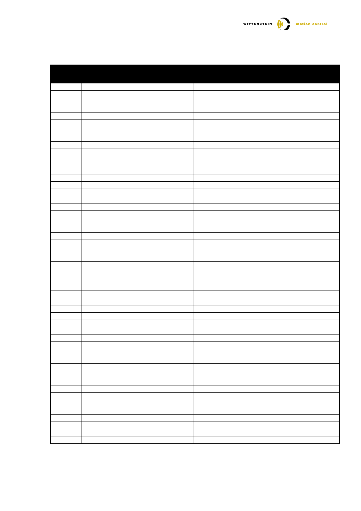
6 Parameters TPMA 025 - 110 600V
Data for combinations not shown here are available on demand.
Code Description TPMA025 TPMA050 TPMA110
Statorlength 15 15 60
S-0-0141
P-0-4014
P-0-0001
P-0-0018
P-0-0051
P-0-0074
P-0-0109
P-0-0508
P-0-0510
P-0-4016
P-0-4017
P-0-4048
S-0-0043
S-0-0055
S-0-0085
S-0-0092 Bipolar torque / force limit value
S-0-0106
S-0-0107
S-0-0109
S-0-0111
S-0-0113
S-0-0116
S-0-0201
S-0-0204
S-0-0100
S-0-0101
P-0-0004
P-0-0525
S-0-0206
S-0-0207
P-0-0540
Motor type
Type of motor
Switching frequency [kHz]
Number of pole pairs
Torque constant [Nm/Aeff]
Encoder type 1 (motor encoder)
Resolver / EnDat / Hiperface
Torque peak limit i = 110 [%]
Torque peak limit i = 154 [%]
Torque peak limit i = 220 [%]
Commutation offset Resolver / EnDat
Commutation offset Hiperface
Rotor inertia
i =110 without brake [kgm²]
i =110 with brake [kgm²]
i =154 without brake [kgm²]
i =154 with brake [kgm²]
i =220 without brake [kgm²]
i =220 with brake [kgm²]
Direct-axis inductance of motor [mH]
Quadrature-axis inductance of motor [mH]
Stator resistance [Ohm]
Velocity polarity parameter
Resolver / EnDat / Hiperface
Position polarities
Resolver / EnDat / Hiperface
Torque polarity parameter
Resolver / EnDat / Hiperface
i = 110
Bipolar torque / force limit value
Bipolar torque / force limit value
Current loop proportional gain 1 [V/A]
Current loop integral action time 1 [ms]
Motor peak current i= 110 [Aeff]
Motor peak current i= 154 [Aeff]
Motor peak current i= 220 [Aeff]
Motor current at standstill [Aeff]
Maximum motor speed [1/min]
Feedback 1 resolution
Resolver / EnDat / Hiperface
Motor warning temperature [°C]
Motor shutdown temperature [°C]
Velocity loop proportional gain [As/rad]
Velocity loop integral action time [ms]
Velocity loop smoothing time constant [µs]
Holding brake control word
Drive on delay time [ms]
Drive off delay time [ms]
Torque of holding brake [Nm]
i = 154
i = 110
TPMA025 TPMA050 TPMA110
0 0 0
8 8 8
6 6 6
0,76 1,02 0,91
10 / 8 / 4
304 381 271
238 313 188
160 197 126
512
341
0,000089 0,000243 0,001032
0,000098 0,000266 0,001208
0,000087 0,000235 0,001000
0,000096 0,000258 0,001175
0,000087 0,000231 0,000984
0,000095 0,000254 0,001159
6,3 6,3 1,2
6,3 6,3 1,2
9,20 4,50 0,36
0111 / 0000 / 0000
1111 / 0000 / 0000
0111 / 0000 / 0000
304 381 271
238 313 188
160 197 126
20 27,5 5,3
0,7 2,78 6,67
7 13,7 41,4
5,5 11,3 28,8
3,7 7,1 19,2
2,30 3,60 15,30
6000 5000 4500
1 / 2048 / 1024
130 130 130
145 145 145
0.2 0.2 0.2
10 10 10
250 250 250
100
100
25 35 50
6 7 10
1,8 4 15
100
3
In case of TPM without brake, the parameter P-0-0525 has to be set to 0.
Document-No.: 4091-D010027-02 Date: 19. October 2005 Page 8 of 15
Page 9
Quick Startup Guide Bosch Rexroth IndraDrive
7 Temperature sensor monitoring of the TPM
The TPM is available with different types of temperature sensors
Please choose the fitting parameters according to your TPM out of the attached list.
The PTC can be used to shutdown the motor in case of over temperature.
With the KTY84-130 you can do an additional temperature measurement.
7.1 TPM with KTY 84-130
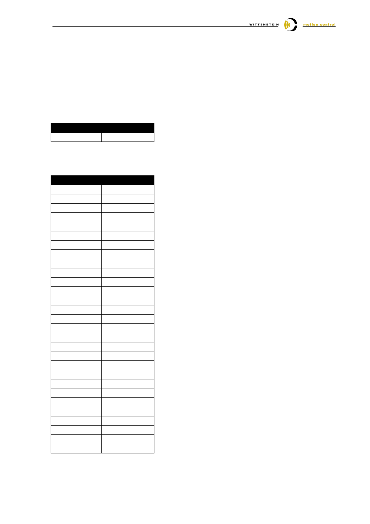
Code Wert
P-0-512 3
7.2 TPM with PTC STM160
Code Wert
P-0-0512 100
P-0-0513 #0 20
P-0-0513 #1 30
P-0-0513 #2 40
P-0-0513 #3 50
P-0-0513 #4 60
P-0-0513 #5 70
P-0-0513 #6 80
P-0-0513 #7 90
P-0-0513 #8 100
P-0-0513 #9 110
P-0-0513 #10 120
P-0-0513 #11 130
P-0-0513 #12 140
P-0-0513 #13 150
P-0-0513 #14 160
P-0-0513 #15 200
P-0-0513 #16 250
P-0-0513 #17 425
P-0-0513 #18 940
P-0-0513 #19 2665
P-0-0513 #20 4000
P-0-0513 #21 4001
P-0-0513 #22 4002
P-0-0513 #23 4003
P-0-0513 #24 4004
P-0-0513 #25 4005
P-0-0513 #26 4006
P-0-0513 #27 4007
Document-No.: 4091-D010027-02 Date: 19. October 2005 Page 9 of 15
Page 10
Quick Startup Guide Bosch Rexroth IndraDrive
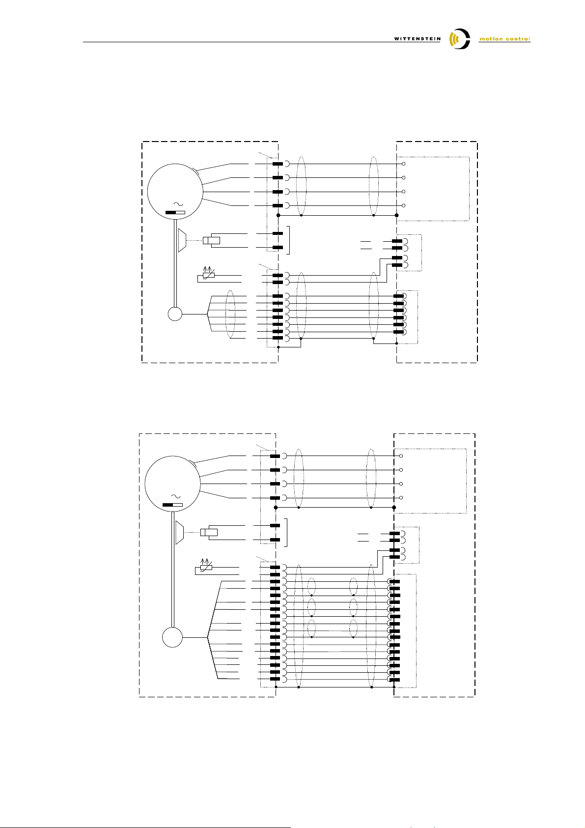
8 Connection schematic TPM / TPMA ⇔⇔⇔⇔ IndraDrive
For detailed information about cable design and screening the documentation of the drive manufacturer
has to be consulted.
8.1 TPM / TPMA with resolver feedback
power plug
PE
M
3
R
PE
W
Br +
Br -
feedback plug
PTC / KTY
PTC / KTY
Ref+
Ref-
Sin +
Sin -
Cos +
Cos -
shield
2
U
4
V
1
5
6
5
6
7
8
3
4
1
2
9
brake optional
Br +
Br -
PE
power
A1
terminal
A2
block
(X5)
A3
brake / Temp.Sensor
(X6)
3
+24VBr
4
0VBr
1
MotTemp+
2
MotTemp-
Bosch Rexroth
IndraDrive
12
VCC_Encoder
4
GND-Encoder
2
A+
encoder
A-
9
3
B+
B-
interface
EN1
10
8.2 TPM / TPMA with absolute rotary encoder ECN 1113 / EQN 1125 / ECN 1313
/ EQN 1325
M
3
SC
power plug
PE
Br +
Br -
feedback plug
PTC / KTY
PTC / KTY
A+
A-
B+
B-
Daten +
Daten -
Takt +
Takt -
P-Encoder
5V Sense
M-Encoder
0V Sense
PE
1
U
2
V
6
W
4
5
8
9
1
2
17
11
12
17
3
13
17
5
14
10
16
7
15
brake optional
Br +
Br -
PE
power
A1
terminal
A2
block
(X5)
A3
Brake / Temp.Sensor
(X6)
+24VBr
3
4
0VBr
1
MotTemp+
2
MotTemp-
Bosch Rexroth
IndraDrive
7
A+
8
A-
14
GND_Schirm
6
B+
5
B-
14
GND_Schirm
9
EncData+
15
EncData-
14
GND_Schirm
11
EncCLK+
13
EncCLK-
12
VCC_Encoder
1
Sense+
10
GND_Encoder
2
Sense-
encoder
interface
EN2
Document-No.: 4091-D010027-02 Date: 19. October 2005 Page 10 of 15
Page 11
Quick Startup Guide Bosch Rexroth IndraDrive
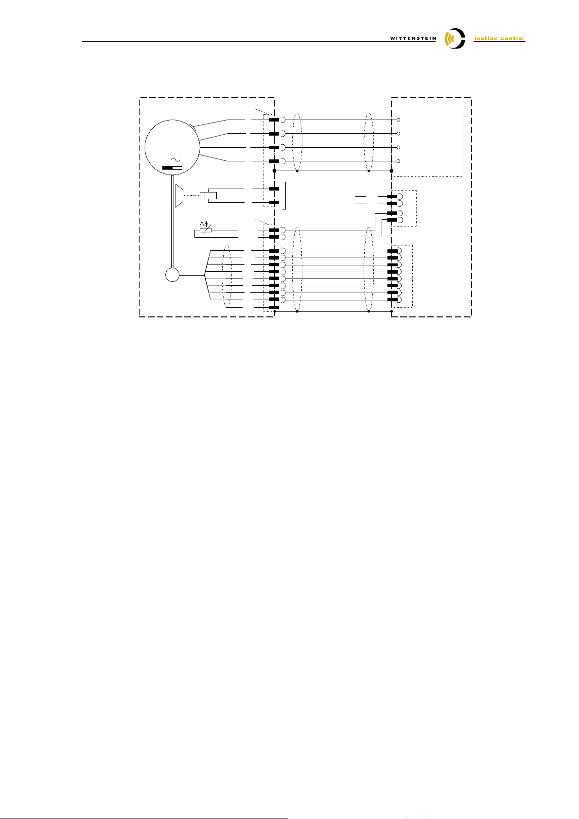
8.3 TPM / TPMA with absolute rotary encoder Hiperface SRS50 / SRM50
M
3
HIP
power plug
PE
W
Br +
Br -
feedback plug
PTC / KTY
PTC / KTY
cos
Refcos
sin
Refsin
+485
-485
8V
GND
shield
PE
1
U
2
V
6
4
5
3
4
8
1
5
6
2
7
12
10
9
brake optional
Br +
Br -
PE
power
A1
terminal
A2
block
(X5)
A3
brake / Temp.Sensor
(X6)
3
+24VBr
4
0VBr
1
MotTemp+
2
MotTemp-
Bosch Rexroth
IndraDrive
2
A+
3
5
6
7
8
11
4
encoder
A-
interface
B+
ENS
BEncData+
EncDataVCC_Encoder
GND_Encoder
Document-No.: 4091-D010027-02 Date: 19. October 2005 Page 11 of 15
Page 12

Quick Startup Guide Bosch Rexroth IndraDrive
9 Diagnostic messages during initial start-up
During initial start-up faults may occur. Following diagnostic messages could appear with an correctly
working TPM. For further investigations please consult the documentation from Bosch Rexroth.
Diagnostic message Possible cause Solution
F2028 Excessive deviation
F8078 Velocity loop error
F8079 Velocity limit S-0-0091 exceeded
F2074 Absolute encoder out of window
F2075
F2076
E2063 Velocity command value >
limit S-0-0091
F2018 Device overtemperature shutdown
F2019 Motor overtemperature shutdown
F2021 Motor temperature monitor
defective
F2022 Device temperature monitor
defective
Commutation angle
not correct
Check wiring of motor and motor
feedback. Verify that P-0-0508 was
taken over correctly by the drive. If
not please activate the commutation angle determination routine.
Initial start-up Set absolute measurement
Speed command
exceeds the value
for bipolar limit in S0-091
Wrong parameterisation of temperature sensor
Adjust the value for S-0-0091 according your application.
Verify the scaling of your application.
Reconfigure the parameters P-00512 and P-0-0513 according to
your TPM.
Document-No.: 4091-D010027-02 Date: 19. October 2005 Page 12 of 15
Page 13
Quick Startup Guide Bosch Rexroth IndraDrive
bac k
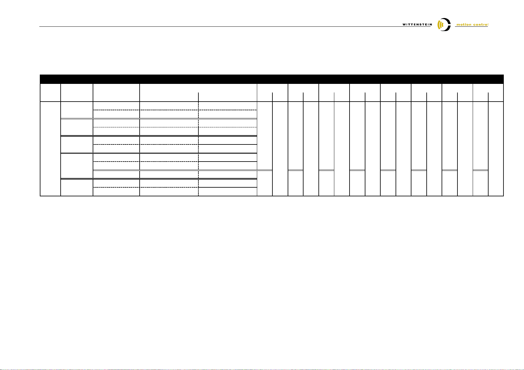
10 Assignment TPM / TPMA ⇔⇔⇔⇔ servo amplifier ⇔⇔⇔⇔ cable set
10.1 TPM / TPMA with resolver feedback
TP M type Contro ller
Feed-
Resolver
1
W MC rec ommendation is based on u se of a power stage with maximal PWM -freque ncy. Plea se refer to WMC o r co ntroller manufacture to select optimized controller size for the app lication. Possibly you
Power and Feedback cables for T PM with R eso lver
all c able com plete a nd f or dynam ic laying
pow er c able TPM 004-050 KABELL-TPM_-xxINDE -RES015-STG structure power c able : 4 x 1,5mm2 + 2 x (2 x 1m m2), diame ter 1 2,2m m, min . bending radius 122mm
pow er c able TPM 110 KABELL-TPM_-xxINDE -RES025-STG structure power c able : 4 x 2,5mm2 + 2 x (2 x 1m m2), diame ter 1 5,1m m, min . bending radius 151mm
feedback cable KABELS-TPM_-xxBOID -RES000-ST G structure fe edb ack cable: 5 x ( 2 x 0 ,25mm2 ) dia meter 9,8mm; m in b ending radiu s 98mm
i
size 320 V 600 V L S L S L S L S L S L S L S L S
TPM 004
TPM 010
TPM(A) 025
TPM(A) 050
TPM(A) 110
021 , 031, 061, 0 91 - HCS 02.1E-W 0012
021 , 031, 061, 0 91 - HCS 02.1E-W 0012
021 , 031, 061, 0 91 - HCS 02.1E-W 0012
110 , 154, 220 - HCS 02.1E-W 0012
061 - HCS02.1E-W0012
091 , 110, 154, 2 20 - H CS02.1E-W 0028
021 , 031 - HCS02.1E-W0054
021 , 031, 061, 0 91 - H CS02.1E-W 0054
110 , 154, 220 - H CS02.1E-W 0054
(xx = cable lengt h)
recommendation W MC
-
-
1
5m 1 0m 15m 20m 30m 25m
4000 3876
4000 6328
4000 3877
4001 2031
4000 6329
Article code for power (L) and feedback (S) cables
4000 3878
4001 2656
4000 6330
4000 3879
4001 2657
4000 6331
4000 6169
4001 2658
4000 7688
4000 6093
4001 2658
4000 7689
40m 50m
4000 7678
4001 2660
4000 7690
4000 7452
4001 2661
4000 7691
4001 2662
Document-No.: 4091-D010027-02 Date: 19. October 2005 Page 13 of 15
Page 14
Quick Startup Guide Bosch Rexroth IndraDrive
TP M type
Co ntrolle r
Article code f or p ow er (L) and fe edb ack (S ) ca bles
rec om mendation W MC
5m
10m
15m
20m
25 m
30m
40m
50m
back
W MC re comm endation is ba sed on use of a power stage with m axim al PW M-frequency. Pleas e refer to WMC or controller m an ufactur e to select optimized controller s ize for the application. Possib ly you
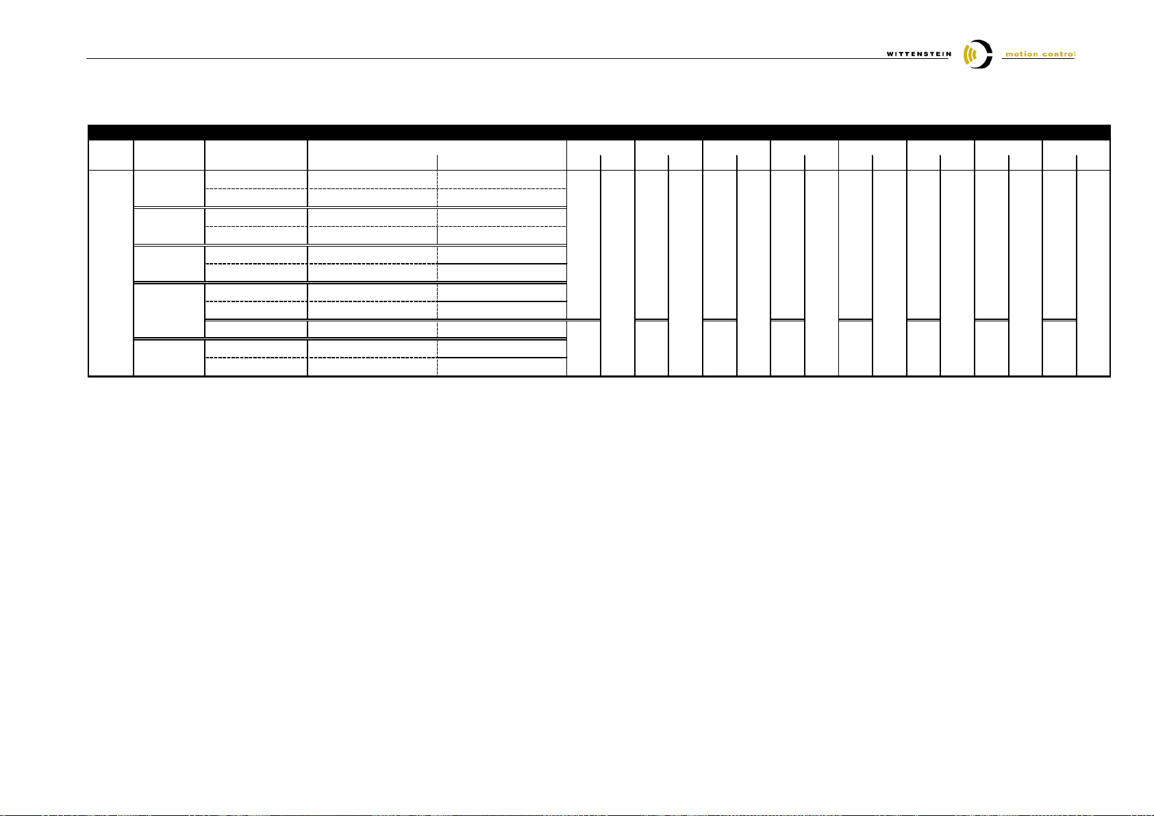
10.2 TPM / TPMA with absolute encoder ECN 1113 / EQN 1125 / ECN 1313 / EQN 1325
Feed-
size i
1
320V 600V L S L S L S L S L S L S L S L S
021, 031, 061 , 09 1 - H CS02.1 E-W 0012
-
021, 031, 061 , 09 1 - H CS02.1 E-W 0012
-
021, 031, 061 , 09 1 - H CS02.1 E-W 0012
110, 154, 220 - HCS02.1E- W 001 2
061 - HCS0 2.1E-W 0012
091, 110, 154 , 22 0 - H CS02.1 E-W 0028
4000 5465
4000 5466
4001 2616
4000 5467
4001 2624
4000 5468
4001 2625
4000 6054
4001 2626
4000 7679
4001 2627
4000 7328
4001 2628
4001 2629
Interface
EnDat
Single-/Multiturn feedback
with
TP M 004
TP M 010
TP M(A) 025
TP M(A) 050
021, 031 - H CS 02.1E-W0054
TP M(A) 110
Absolute
1
021, 031, 061 , 09 1 - H CS02.1 E-W 0054
110, 154, 220 - HCS02.1E- W 005 4
4000 6830
4000 6831
4000 6832
4000 6833
4000 7692
4000 7693
4000 7694
Power an d F eed back cables for TPM w ith En Dat ab solute fee db ack EC N 1 113 / EQN 1125 / ECN13 13 / EQ N1325
all cable complete an d for dynam ic layin g
power cab le TPM 0 04- 050 KA BEL L-TPM_ -xxSTD_-END01 5-STG str uctu re power cable : 4 x 1,5mm 2 + 2 x 1m m2, dia me ter 12m m, min . be nding r adiu s 1 20m m
power cab le TPM 1 10 KA BEL L-TPM_ -xxSTD_-END02 5-STG
fee dba ck cab le KAB ELS -TP M_-xxBOID-E ND 000 -STG struc ture fee dba ck cab le: 3 x (2 x 0,1 4mm2) + 4 x 0,14m m2 + 4 x 0,25mm2 + 2 x 0,5m m2 ; diameter 10m m
(xx = ca ble len gth)
str uctu re power cable : 4 x 2,5mm 2 + 2 x 1m m2, dia me ter 15,1 mm , m in. bending radius 151mm
dia me ter 10m m; min . be nding radius 1 00m m
4000 5920
4001 2630
4000 7695
Document-No.: 4091-D010027-02 Date: 19. October 2005 Page 14 of 15
Page 15
Quick Startup Guide Bosch Rexroth IndraDrive
all cable complete an d for dynam ic layin g
W MC re com men dation is based on use of a powe r stage with m aximal PW M-frequ enc y. Pleas e re fer to WMC or c ontroller m anufacture to select optimized c ontroller size for the a pplication. Pos sibly you
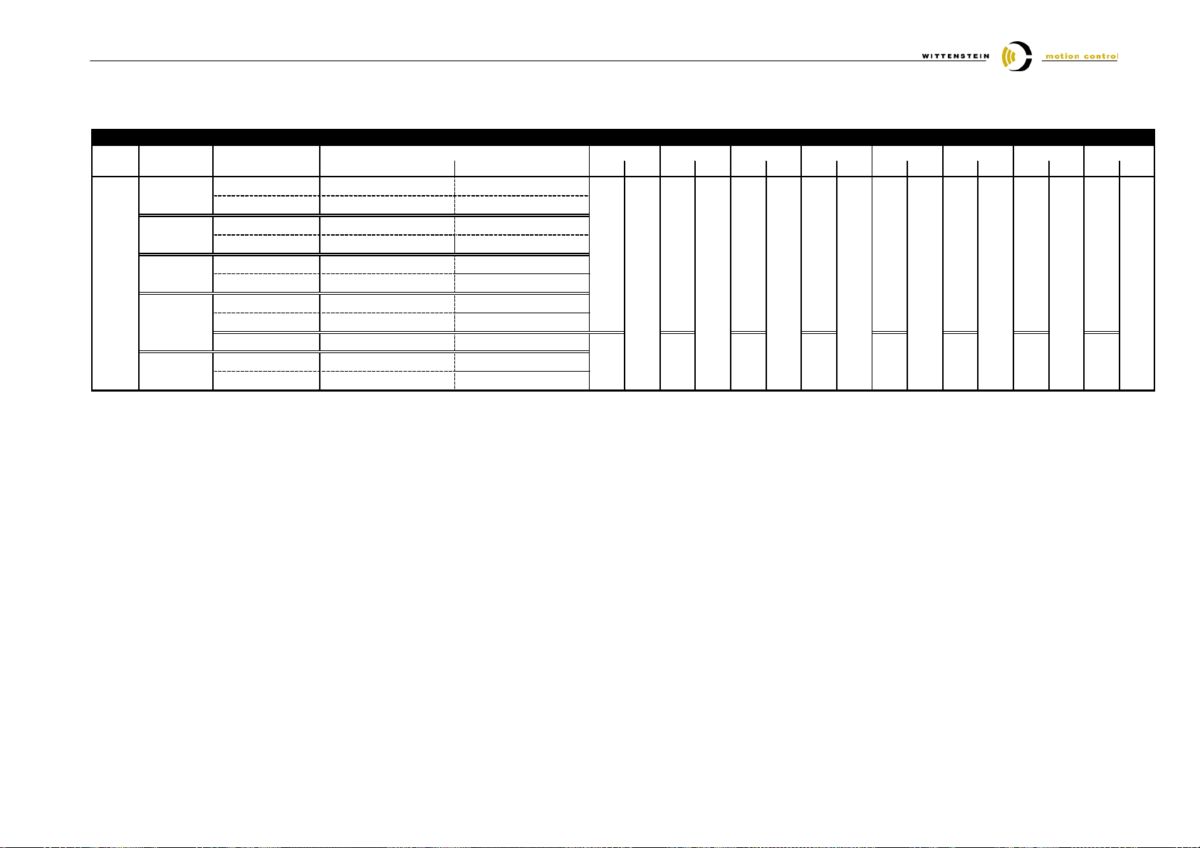
Power an d F eed back cables for TPM w ith Stegm an n H iperface S RS 50 / SR M 50
50m
25 m
30m
40m
20m5m10m
15m
back
rec om mendation W MC
TP M type
Co ntrolle r
Article code f or p ow er (L) and feedb ack (S) ca bles
10.3 TPM / TPMA with absolute encoder SRS 50 / SRM 50
Feed-
i
1
size 32 0V 6 00V L S L S L S L S L S L S L S L S
TP M 004
021, 031, 061, 09 1 - HCS02.1 E-W 0012
-
TP M 010
Interface
TP M(A) 025
Single-/Multiturn feedback
Hiperface
TP M(A) 050
with
TP M(A) 110
Absolute
1
power cab le TPM 0 04- 050 KA BEL L-TPM_-xxSTD_-END015-STG structu re powe r cable :
power cab le TPM 1 10 KA BEL L-TPM_-xxSTD_-END025-STG structu re powe r cable : 4 x 2,5 mm 2 + 2 x (2 x 1m m2), diame ter 15,1mm , m in. ben ding radius 15 1mm
fee dba ck cab le KAB ELS -TP M_-xxBOID-H IP0 00-STG
021, 031, 061, 09 1 - HCS02.1 E-W 0012
-
021, 031, 061, 09 1 - HCS02.1 E-W 0012
110, 154, 220 - HCS02.1E-W 001 2
061 - HCS0 2.1E-W 0012
091, 110, 154, 22 0 - HCS02.1 E-W 0028
021, 031 - H CS 02.1E-W0054
021, 031, 061, 09 1 - HCS02.1 E-W 0054
110, 154, 220 - HCS02.1E-W 005 4
(xx = ca ble len gth)
4000 5465
4000 6830
str uctu re feed bac k cable : 5 x (2 x 0,25m m2) diameter 9,8 mm ; min bend ing radius 98m m
4000 5466
4001 1927
4000 6831
4000 5467
4001 1928
4000 6832
4 x 1,5mm 2 + 2 x (2 x 1mm 2), dia meter 12,2 mm , m in. b end ing rad ius 122 mm
4000 5468
4001 1929
4000 6833
4000 6054
4001 1930
4000 7692
4000 7679
4001 1932
4001 1933
4000 7693
4000 7328
4001 1934
4000 7694
4000 5920
4001 1935
4000 7695
Document-No.: 4091-D010027-02 Date: 19. October 2005 Page 15 of 15
 Loading...