

Page 1
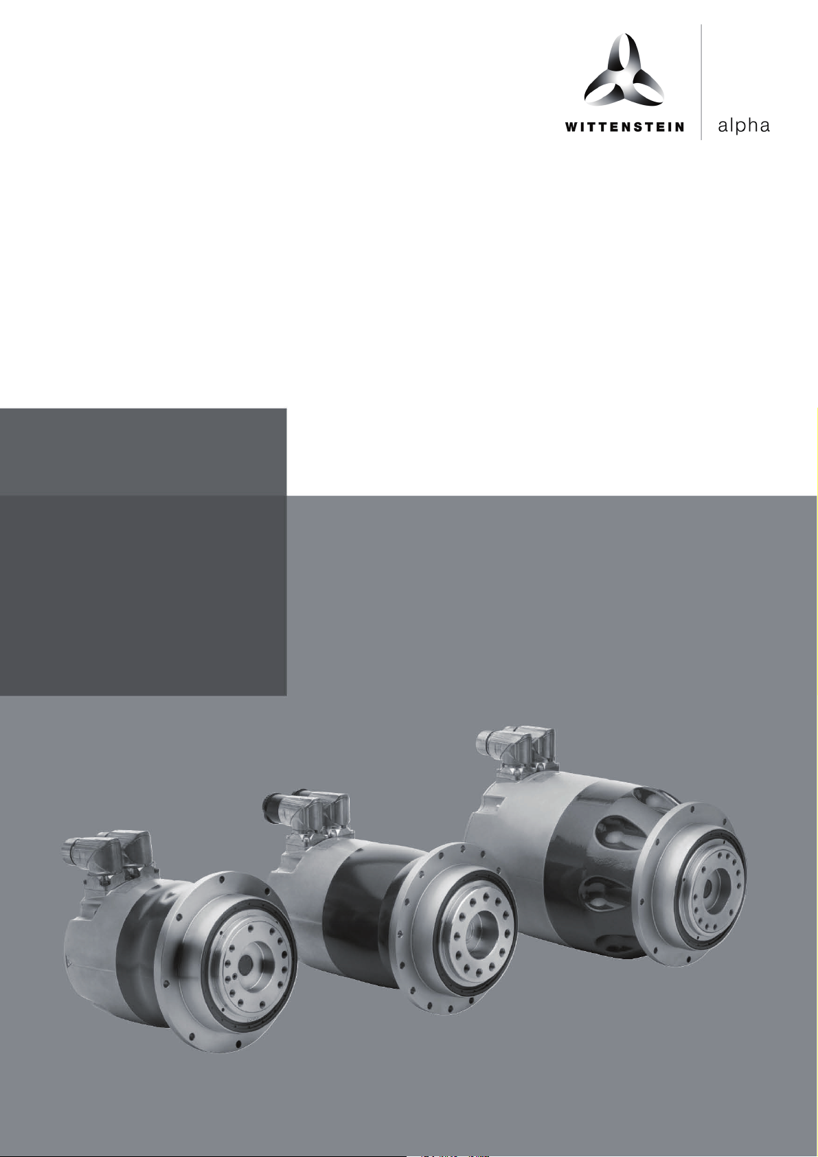
4091-D012345
00
TPM
+
Siemens SINAMICS S120
Quick Startup Guide
4091-D032124
Revision: 02
Page 2
Revision
Date
Comment
Chapter
01 27th
July 2012
First release
All
02 27th
March 2017
Transition to Wittenstein alpha
All
Quick Startup Guide TPM+
Revision history
Service
In case you have technical questions,
please contact:
WITTENSTEIN alpha GmbH
Customer Service
Walter-Wittenstein-Straße 1
D-97999 Igersheim
Tel.: +49 (0) 79 31 / 493- 12900
Fax: +49 (0) 79 31 / 493- 10903
E-Mail: [email protected]
© WITTENSTEIN alpha GmbH 2017
This documentation is copyright protected.
WITTENSTEIN alpha GmbH reserves all the rights to photo-mechanical
reproduction, copying, and the distribution by special processes (such as computers,
file media, data networks), even in parts.
Subject to technical and content changes without notice.
Page en-1
Revision: 02 4091- D032124 Date: 27th March 2017
Page 3

TPM+ Quick Startup Guide
Table of Contents
Revision history ........................................................................................................ 1
1 General Information ............................................................................................ 4
1.1 Description, designations ................................................................................ 4
1.2 Whom does this manual concern? .................................................................. 4
1.3 Which signs and symbols are referred to in this manual? ............................... 4
1.4 Exclusion of liability ......................................................................................... 4
1.5 EC low-voltage directive / EMC regulations .................................................... 4
1.6 Copyright ........................................................................................................ 4
2 Safety ................................................................................................................... 5
2.1 Intended use ................................................................................................... 5
2.2 Improper use................................................................................................... 5
2.3 Safety Instructions .......................................................................................... 5
3 Type plate information – identification ............................................................. 7
3.1 Identification plate, designation....................................................................... 7
4 Setting the parameters ....................................................................................... 8
4.1 Configuration Encoder TPM+ Resolver ........................................................... 9
4.2 Configuration Encoder TPM+ Heidenhain EnDat Multiturn or Singleturn ........ 9
4.3 Configuration Encoder TPM+ incremental encoder Heidenhain ERN1185 ..... 9
4.4 Parameter TPM+ Dynamic 004 560V ........................................................... 10
4.5 Parameter TPM+ Dynamic 010 560V ........................................................... 11
4.6 Parameter TPM+ Dynamic 025 560V ........................................................... 12
4.7 Parameter TPM+ Dynamic 050 560V ........................................................... 13
4.8 Parameter TPM+ Dynamic 110 560V ........................................................... 14
4.9 Parameter TPM+ Power 004 560V ............................................................... 15
4.10 Parameter TPM+ Power 010 560V ............................................................ 16
4.11 Parameter TPM+ Power 025 560V ............................................................ 17
4.12 Parameter TPM+ Power 050 560V ............................................................ 18
4.13 Parameter TPM+ Power 110 560V ............................................................ 19
4.14 Parameter TPM+ High Torque 010 560V .................................................. 20
4.15 Parameter TPM+ High Torque 025 560V .................................................. 21
4.16 Parameter TPM+ High Torque 050 560V .................................................. 22
4.17 Parameter TPM+ High Torque 110 560V .................................................. 23
Page en-2
Revision: 02 4091-D032124 Date: 27th March 2017
Page 4

Quick Startup Guide TPM+
5 Connection schematic TPM+ ........................................................................... 24
5.1 TPM+ with resolver ........................................................................................ 24
5.2 TPM+ with absolute encoder Heidenhain EnDat EQN 1125 ......................... 25
5.3 TPM+ with incremental encoder Heidenhain ERN1185 ................................ 26
Page en-3
Revision: 02 4091- D032124 Date: 27th March 2017
Page 5

TPM+ Quick Startup Guide
1 General Information
1.1 Description, designations
The AC servo actuator TPM+ (hereafter referred to as servo actuator) is a
combination of a low-backlash planetary gearhead and an AC servo motor.
The following manual contains the following points:
•••• Safety Instructions
•••• Parameter lists for the TPM+ series
•••• Connection schematic for TPM+
1.2 Whom does this manual concern?
This manual concerns all persons who install, operate, or maintain this servo
actuator.
They may only carry out work on the servo actuator, if they have read and understood
this operating manual. Please pass the safety instructions on to other persons as
well.
1.3 Which signs and symbols are referred to in this manual?
An “action instruction”, which requires you to carry out an action.
∇∇∇∇ With a “check” you can specify whether the device is ready for the next work
stage.
☺☺☺☺ A “usage tip” shows you an option of facilitating or improving operations.
The safety instructions symbols are described in section 2 “Safety”.
1.4 Exclusion of liability
WITTENSTEIN alpha is not liable for damages or injury caused by:
•••• Improper utilization of the servo actuator and the servo amplifier or
•••• Incorrect setting of operating parameters.
1.5 EC low-voltage directive / EMC regulations
The servo actuator has been constructed in accordance with EC directive 73/23/EEC.
During installation and connection of the electrical components, the relevant regulations have to be observed (for example wire cross sections, fuse protection, etc.).
Meeting all requirements for the entire system is the responsibility of the system's
manufacturer.
You may only operate the equipment if you comply to the national EMC regulations
(refer to the servo amplifier documentation for installation information pertaining to
EMC) as they are defined for the given application.
1.6 Copyright
© 2017, WITTENSTEIN alpha GmbH
All of the product brand names which appear in this manual are trademarks of the
relevant companies. If the ® and/or ™ symbols are omitted, this does imply that the
name is a free brand name.
Page en-4
Revision: 02 4091-D032124 Date: 27th March 2017
Page 6
Quick Startup Guide TPM+
2 Safety
2.1 Intended use
The servo actuator is designed for industrial applications. Its purpose is to drive
machines. Please refer to our catalogue or our Internet page for the maximum
permitted speeds and torques: www.wittenstein-alpha.de
Please consult our technical service if your servo actuator is more than a year
old. In this way you receive valid data.
Please be sure to read the documentation provided by the manufacturer of the
servo actuator.
2.2 Improper use
Any use transgressing the above-named restrictions (especially higher torques and
speeds) is not compliant with the regulations, and is thus prohibited.
The operation of the servo actuator is prohibited if:
•••• It was not installed according to regulations (for example fastening bolts).
•••• The servo actuator is very dirty, damaged or blocked.
•••• It is operated without lubricant.
•••• The cables are damaged or improperly connected.
•••• The operating parameters have not been set properly.
2.3 Safety Instructions
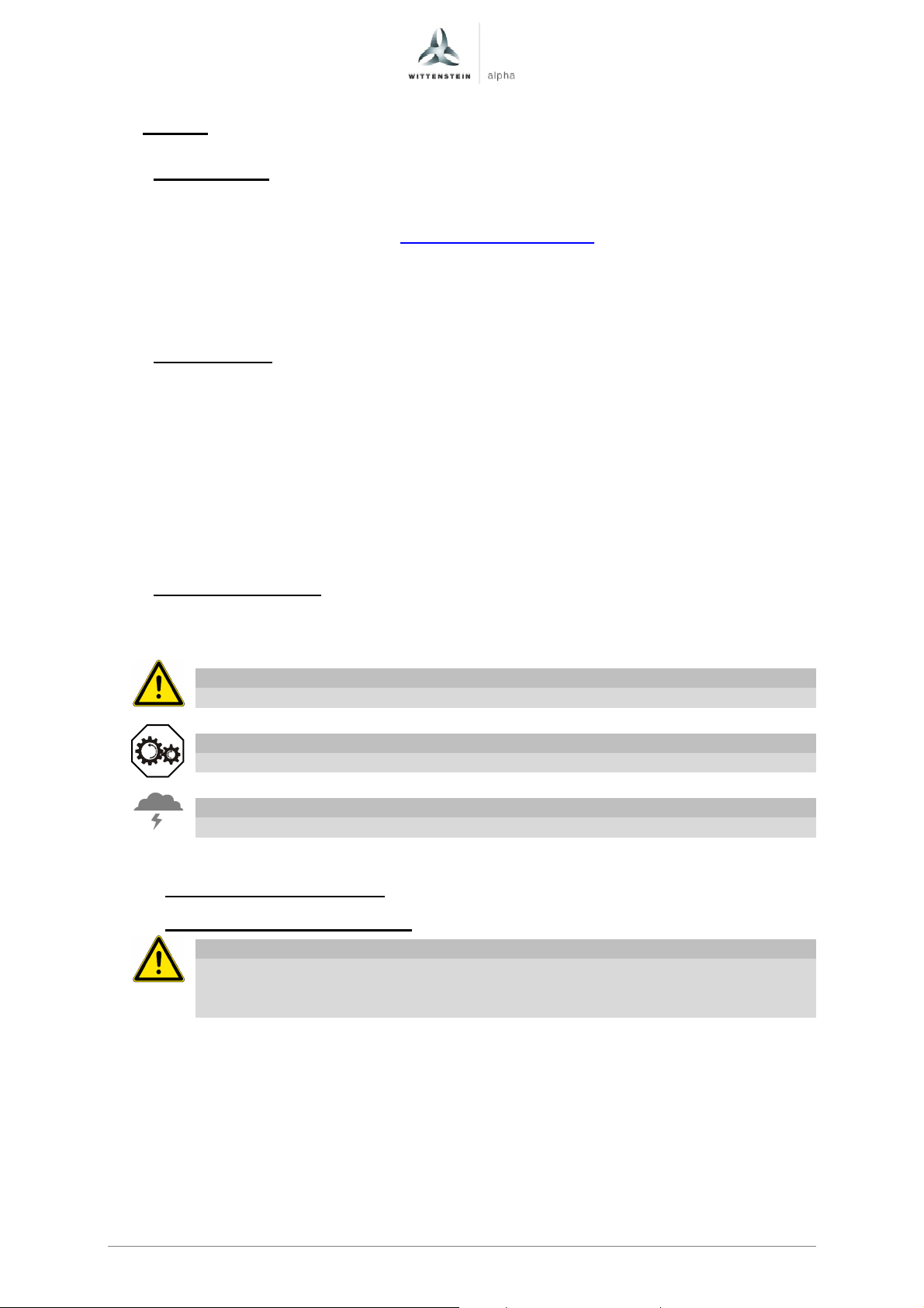
The following symbols are used in this manual to warn you of hazards:
2.3.1
DANGER!
This symbol warns you of danger of injury to yourself and others.
Attention
This symbol warns you of the risk of damage to the servo actuator.
Environment
This symbol warns of environmental pollution risk.
General safety instructions
Working on the servo actuator
DANGER!
Improperly executed work can lead to injury and damage.
Always ensure that the servo actuator is only installed, maintained, and
dismantled by trained technicians.
Page en-5
Revision: 02 4091- D032124 Date: 27th March 2017
Page 7
TPM+ Quick Startup Guide
DANGER!
Current-flow through the body or arcing can lead to grave injury and death.
Only perform tasks on the electrical system if you are:
•••• A trained electrician.
•••• A person trained in electro-technology, working under the supervision of a
specialist electrician.
Always adhere to the five safety rules for the de-energised state:
•••• De-energise.
•••• Secure against being turned on (for example by locking it).
•••• Ensure that de-energised state exists.
•••• Attach ground line and short-circuit the equipment.
•••• Cover and safeguard any live parts in the immediate vicinity.
DANGER!
Impurities spinning through the air can cause grave injury.
Before putting the servo actuator into operation, check that there are no
impurities or tools near it.
Maintenance
An unintentional start of the machine during maintenance work can lead to
serious accidents.
Ensure that no one can start the machine while you are working on it.
Even only briefly running the machine during maintenance work can lead to
accidents if the safety devices are not operating.
Check that all safety devices have been mounted and are activated.
Wiring
Incorrect wiring can lead to injuries and damage.
Only use power and signal cables recommended by WITTENSTEIN alpha.
Do not cut off power and signal cables, and do not insert extensions.
Make sure that the U-U, V-V and W-W motor phases are correctly
connected.
Make sure that the motor encoder interface of the servo controller is
compatible to the servo actuator.
Observe the prescribed voltage for the brakes (usually 24 V DC) and the
polarity.
DANGER!
DANGER!
DANGER!
Page en-6
Revision: 02 4091-D032124 Date: 27th March 2017
Page 8
Quick Startup Guide TPM+
3 Type plate information – identification
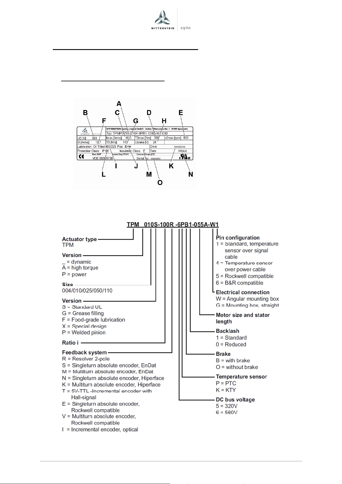
The technical specifications can be found on your servo actuator's type plate
according to the following scheme.
3.1 Identification plate, designation
The following specifications can be found on the identification plate:
A Ordering code
B DC-Bus voltage
C Maximum current
D Maximum torque at gear output
E Maximum gear output speed
F Continuous stall current
G Continuous stall torque at gear output
H Brake voltage
I Lubricant
J Mounting position
K For use with drive
L Type of protection
Bild 4.2
M Insulation class
N Manufacturing date
O Serial number
Page en-7
Revision: 02 4091- D032124 Date: 27th March 2017
Page 9

TPM+ Quick Startup Guide
4 Setting the parameters
The tables in chapter 4 contain all of the parameters that are required for the initial
start-up of a TPM+ servo actuator from WITTENSTEIN alpha at a servo drive
Siemens Sinamics S120.
The parameters can be entered with the Siemens STARTER software in the dialog
“Drive navigator – Device configuration – Carry out drive configuration”.
In the dialog “Calculation of the motor/controller data” enable the checkbox “Complete
calculation without equiv. circuit diag. data”.
When the servo actuator and the servo drive are properly connected, these
parameters guarantee that the servo actuator can be operated at idle with speed
control.
Based on these default settings, you can optimize the dynamics of the speed
controller depending on the application.
Follow the details of the type plate.
Data for combinations not shown here are available on demand.
Page en-8
Revision: 02 4091-D032124 Date: 27th March 2017
Page 10

Quick Startup Guide TPM+
4.1 Configuration Encoder TPM+ Resolver
In the dialog "Configuration - Encoder" of the drive configuration assistant the follwing
settings has to be done:
Encoder name: Resolver
Encoder evaluation: SMC10 xxx
Enable the checkbox „Enter data“
Click on the button „Encoder data“. Enter the following data in the dialog „Encoder
data“:
Measuring system: Resolver
No. of pole pairs: 1
4.2 Configuration Encoder TPM+ Heidenhain EnDat Multiturn
In the dialog "Configuration - Encoder" of the drive configuration assistant select the
code number 2053 512, 1Vpp, A/B, EnDat, Multiturn 4096.
If encoder 2053 is not included in the list the follwing settings have to be entered
manually:
Encoder name: EnDat
Encoder evaluation: SMC20 xxx
Enable the checkbox „Enter data“
Click on the button „Encoder data“. Enter the following data in the dialog „Encoder
data“:
Measuring system: Absolute EnDat protocol
Enable the checkbox „Identify encoder“
4.3 Configuration Encoder TPM+ incremental encoder Heidenhain ERN1185
In the dialog "Configuration - Encoder" of the drive configuration assistant the follwing
settings has to be done:
Encoder name: Incremental
Encoder evaluation: SMC20 xxx
Enable the checkbox „Enter data“
Click on the button „Encoder data“. Enter the following data in the dialog „Encoder
data“:
Measuring system: Incremental sine/cosine
Pulses/revolution: 2048
Encoder type: Incremental – one zero mark
Commutation information: Coarse synchronisation with C/D track
Page en-9
Revision: 02 4091- D032124 Date: 27th March 2017
Page 11
Code
Description
Unit i=16-31
i=61-91
Ratio
Motor inertia
Motor inertia
I
I
TPM+ Quick Startup Guide
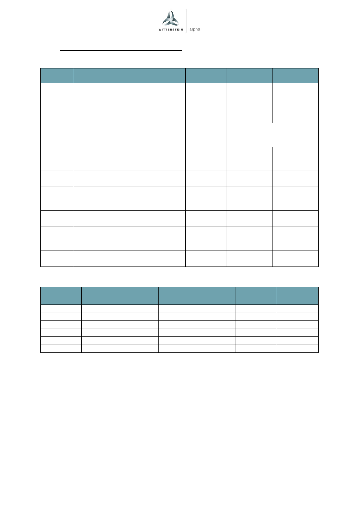
4.4 Parameter TPM+ Dynamic 004 560V
Exceute “Complete calculation without equiv. circuit diag. data” after input.
560 VDC
560 VDC
p305 Rated motor current Arms 1,10 0,80
p311 Rated motor velocity rpm 5000 5000
p314 Motor pole pair number - 4 4
p316 Motor torque constant Nm/Arms 0,70 0,47
p322 Maximum motor speed rpm 6000 6000
p323 Maximum motor current Arms See table below
p338 Motor limit current Arms See table below
p341 Motor moment of inertia kgm² See table below
p350 Motor stator resistance, cold Ohm 14,10 18,70
p356 Motor stator leakage inductance mH 16,65 15,00
p312 Rated motor torque Nm 0,72 0,36
p317 Motor voltage constant Volt 42,2 28,3
p318 Motor stall current Arms 1,10 0,80
p319 Motor stall torque Nm 0,72 0,36
Current controller adaptation,
p391
lower starting point Arms 1,1 0,8
Current controller adaptation,
p392
upper starting point Arms 3,2 2,4
Current controller adaptation,
p393
P gain, scaling upper % 89 87
p1215 1 Motor holding brake configuration - 1 1
p1216 Motor holding brake opening time ms 12 12
p1217 Motor holding brake closing time ms 10 10
1
For actuators without holding brake the parameter p1215 has to be set to 0.
w/o brake[kgm²]
with brake[kgm²]
max_stat
[A
rms
]2
max_dyn
[A
rms
]3
16 0,000021 0,000023 3,20 3,20
21 0,000020 0,000023 2,60 3,20
31 0,000020 0,000022 2,20 3,20
61 0,000012 0,000014 1,40 2,40
64 0,000011 0,000013 1,30 2,40
91 0,000012 0,000014 0,90 2,40
2
Static maximum motorcurrent: Use this maximum current to protect the gear reducer from overload
and to reduce the torque safely to T2B.
3
Dynamic maximum motorcurrent: For dynamic applications the maximum current can be increased
to this value in dependency of the mass moment of inertia relation. We recommend a detailed
calculation with Cymex.
Page en-10
Revision: 02 4091-D032124 Date: 27th March 2017
Page 12
Code
Description
Unit i=16-31
i=61-91
Ratio
Motor inertia
Motor inertia
I
I
Quick Startup Guide TPM+
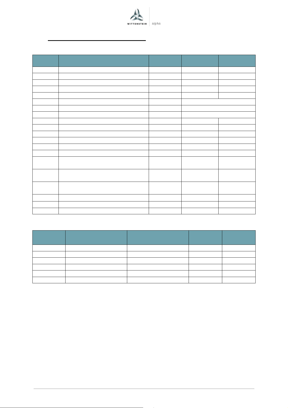
4.5 Parameter TPM+ Dynamic 010 560V
Exceute “Complete calculation without equiv. circuit diag. data” after input.
560 VDC
560 VDC
p305 Rated motor current Arms 1,30 0,90
p311 Rated motor velocity rpm 5000 5000
p314 Motor pole pair number - 4 4
p316 Motor torque constant Nm/Arms 0,97 0,78
p322 Maximum motor speed rpm 6000 6000
p323 Maximum motor current Arms See table below
p338 Motor limit current Arms See table below
p341 Motor moment of inertia kgm² See table below
p350 Motor stator resistance, cold Ohm 10,65 20,00
p356 Motor stator leakage inductance mH 11,40 15,00
p312 Rated motor torque Nm 1,20 0,67
p317 Motor voltage constant Volt 58,5 47,4
p318 Motor stall current Arms 1,30 0,90
p319 Motor stall torque Nm 1,20 0,67
Current controller adaptation,
p391
lower starting point Arms 1,3 0,9
Current controller adaptation,
p392
upper starting point Arms 5,2 3,0
Current controller adaptation,
p393
P gain, scaling upper % 75 81
p1215 1 Motor holding brake configuration - 1 1
p1216 Motor holding brake opening time ms 12 12
p1217 Motor holding brake closing time ms 10 10
1
For actuators without holding brake the parameter p1215 has to be set to 0.
w/o brake[kgm²]
with brake[kgm²]
max_stat
[A
rms
]2
max_dyn
[A
rms
]3
16 0,000032 0,000034 5,20 5,20
21 0,000032 0,000034 5,20 5,20
31 0,000032 0,000034 4,70 5,20
61 0,000017 0,000019 2,20 3,00
64 0,000017 0,000019 2,10 3,00
91 0,000017 0,000019 1,50 3,00
2
Static maximum motorcurrent: Use this maximum current to protect the gear reducer from overload
and to reduce the torque safely to T2B.
3
Dynamic maximum motorcurrent: For dynamic applications the maximum current can be increased
to this value in dependency of the mass moment of inertia relation. We recommend a detailed
calculation with Cymex.
Page en-11
Revision: 02 4091- D032124 Date: 27th March 2017
Page 13
Code
Description
Unit i=16-31
i=61-91
Ratio
Motor inertia
Motor inertia
I
I
TPM+ Quick Startup Guide
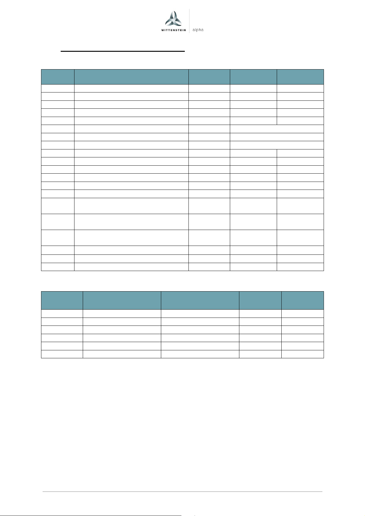
4.6 Parameter TPM+ Dynamic 025 560V
Exceute “Complete calculation without equiv. circuit diag. data” after input.
560 VDC
560 VDC
p305 Rated motor current Arms 5,70 1,90
p311 Rated motor velocity rpm 5000 5000
p314 Motor pole pair number - 6 6
p316 Motor torque constant Nm/Arms 0,98 1,02
p322 Maximum motor speed rpm 6000 6000
p323 Maximum motor current Arms See table below
p338 Motor limit current Arms See table below
p341 Motor moment of inertia kgm² See table below
p350 Motor stator resistance, cold Ohm 1,10 6,75
p356 Motor stator leakage inductance mH 3,00 9,45
p312 Rated motor torque Nm 5,50 1,86
p317 Motor voltage constant Volt 59,5 61,3
p318 Motor stall current Arms 5,70 1,90
p319 Motor stall torque Nm 5,50 1,86
Current controller adaptation,
p391
lower starting point Arms 5,7 1,9
Current controller adaptation,
p392
upper starting point Arms 17,0 6,0
Current controller adaptation,
p393
P gain, scaling upper % 73 72
p1215 1 Motor holding brake configuration - 1 1
p1216 Motor holding brake opening time ms 30 30
p1217 Motor holding brake closing time ms 20 20
1
For actuators without holding brake the parameter p1215 has to be set to 0.
w/o brake[kgm²]
with brake[kgm²]
max_stat
[A
rms
]2
max_dyn
[A
rms
]3
16 0,000216 0,000235 17,00 17,00
21 0,000216 0,000235 17,00 17,00
31 0,000217 0,000236 14,10 17,00
61 0,000077 0,000096 5,90 6,00
64 0,000076 0,000095 5,60 6,00
91 0,000076 0,000095 3,80 6,00
2
Static maximum motorcurrent: Use this maximum current to protect the gear reducer from overload
and to reduce the torque safely to T2B.
3
Dynamic maximum motorcurrent: For dynamic applications the maximum current can be increased
to this value in dependency of the mass moment of inertia relation. We recommend a detailed
calculation with Cymex.
Page en-12
Revision: 02 4091-D032124 Date: 27th March 2017
Page 14
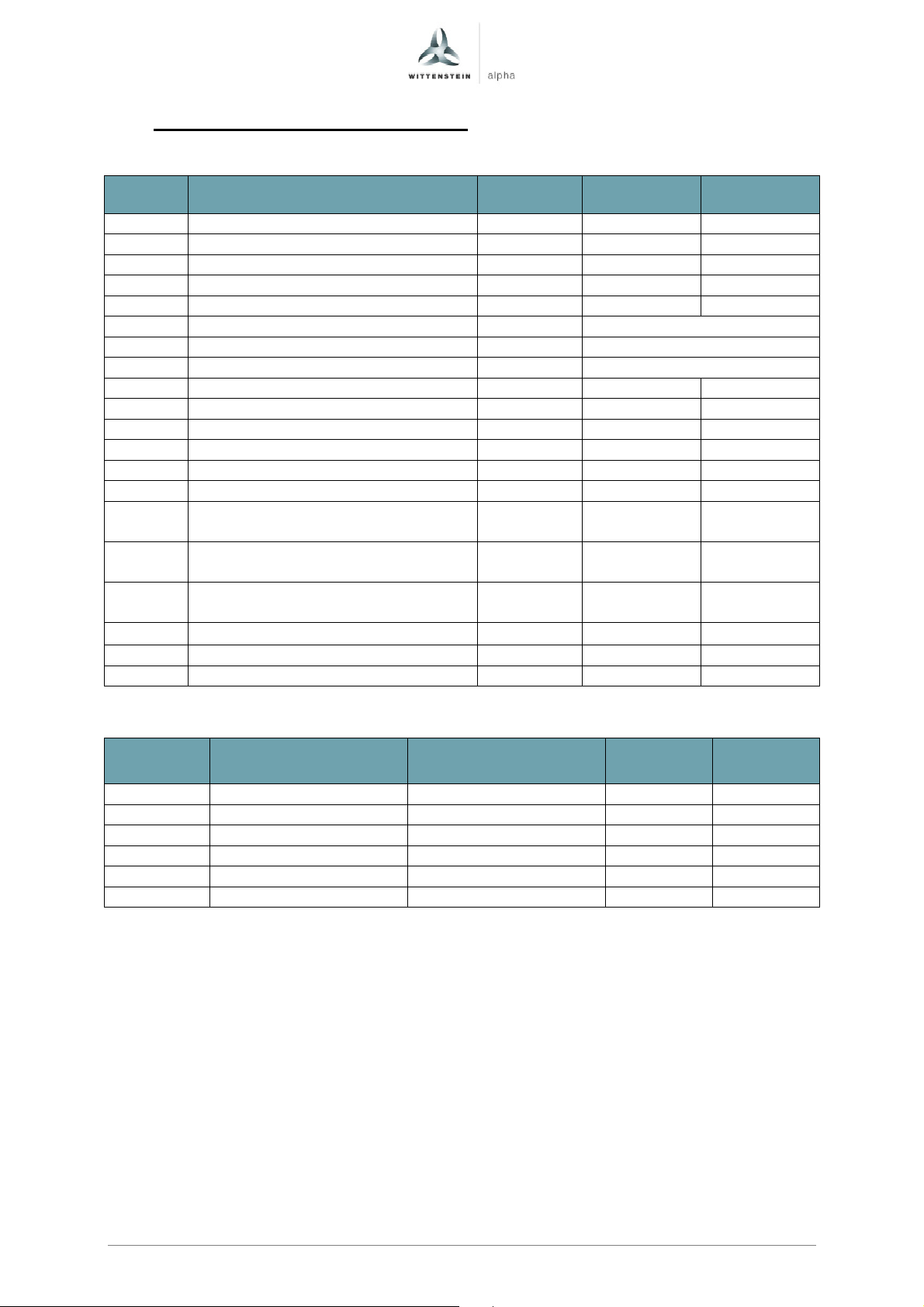
Code
Description
Unit i=16-31
i=61-91
Ratio
Motor inertia
Motor inertia
I
I
Quick Startup Guide TPM+
4.7 Parameter TPM+ Dynamic 050 560V
Exceute “Complete calculation without equiv. circuit diag. data” after input.
560 VDC
560 VDC
p305 Rated motor current Arms 13,70 3,80
p311 Rated motor velocity rpm 4167 4167
p314 Motor pole pair number - 6 6
p316 Motor torque constant Nm/Arms 1,00 0,97
p322 Maximum motor speed rpm 5000 5000
p323 Maximum motor current Arms See table below
p338 Motor limit current Arms See table below
p341 Motor moment of inertia kgm² See table below
p350 Motor stator resistance, cold Ohm 0,22 2,00
p356 Motor stator leakage inductance mH 1,50 5,55
p312 Rated motor torque Nm 13,49 3,59
p317 Motor voltage constant Volt 61,0 58,7
p318 Motor stall current Arms 13,70 3,80
p319 Motor stall torque Nm 13,49 3,59
Current controller adaptation,
p391
lower starting point Arms 13,7 3,8
Current controller adaptation,
p392
upper starting point Arms 40,0 12,0
Current controller adaptation,
p393
P gain, scaling upper % 72 67
p1215 1 Motor holding brake configuration - 1 1
p1216 Motor holding brake opening time ms 42 42
p1217 Motor holding brake closing time ms 20 20
1
For actuators without holding brake the parameter p1215 has to be set to 0.
w/o brake[kgm²]
with brake[kgm²]
max_stat
[A
rms
]2
max_dyn
[A
rms
]3
16 0,000907 0,001007 40,00 40,00
21 0,000907 0,001007 34,30 40,00
31 0,000894 0,000993 29,40 40,00
61 0,000251 0,000351 12,00 12,00
64 0,000249 0,000349 12,00 12,00
91 0,000249 0,000349 8,40 12,00
2
Static maximum motorcurrent: Use this maximum current to protect the gear reducer from overload
and to reduce the torque safely to T2B.
3
Dynamic maximum motorcurrent: For dynamic applications the maximum current can be increased
to this value in dependency of the mass moment of inertia relation. We recommend a detailed
calculation with Cymex.
Page en-13
Revision: 02 4091- D032124 Date: 27th March 2017
Page 15

Code
Description
Unit i=16-31
i=61-91
Ratio
Motor inertia
Motor inertia
I
I
TPM+ Quick Startup Guide
4.8 Parameter TPM+ Dynamic 110 560V
Exceute “Complete calculation without equiv. circuit diag. data” after input.
560 VDC
560 VDC
p305 Rated motor current Arms 16,70 13,70
p311 Rated motor velocity rpm 4167 4167
p314 Motor pole pair number - 6 6
p316 Motor torque constant Nm/Arms 1,00 1,00
p322 Maximum motor speed rpm 5000 5000
p323 Maximum motor current Arms See table below
p338 Motor limit current Arms See table below
p341 Motor moment of inertia kgm² See table below
p350 Motor stator resistance, cold Ohm 0,16 0,22
p356 Motor stator leakage inductance mH 1,20 1,50
p312 Rated motor torque Nm 16,42 13,49
p317 Motor voltage constant Volt 61,0 61,0
p318 Motor stall current Arms 16,70 13,70
p319 Motor stall torque Nm 16,42 13,49
Current controller adaptation,
p391
lower starting point Arms 16,7 13,7
Current controller adaptation,
p392
upper starting point Arms 70,0 40,0
Current controller adaptation,
p393
P gain, scaling upper % 63 72
p1215 1 Motor holding brake configuration - 1 1
p1216 Motor holding brake opening time ms 42 42
p1217 Motor holding brake closing time ms 20 20
1
For actuators without holding brake the parameter p1215 has to be set to 0.
w/o brake[kgm²]
with brake[kgm²]
max_stat
[A
rms
]2
max_dyn
[A
rms
]3
16 0,001314 0,001414 70,00 70,00
21 0,001314 0,001414 70,00 70,00
31 0,001284 0,001384 70,00 70,00
61 0,000889 0,000988 30,00 40,00
64 0,000883 0,000983 28,30 40,00
91 0,000883 0,000983 18,00 40,00
2
Static maximum motorcurrent: Use this maximum current to protect the gear reducer from overload
and to reduce the torque safely to T2B.
3
Dynamic maximum motorcurrent: For dynamic applications the maximum current can be increased
to this value in dependency of the mass moment of inertia relation. We recommend a detailed
calculation with Cymex.
Page en-14
Revision: 02 4091-D032124 Date: 27th March 2017
Page 16
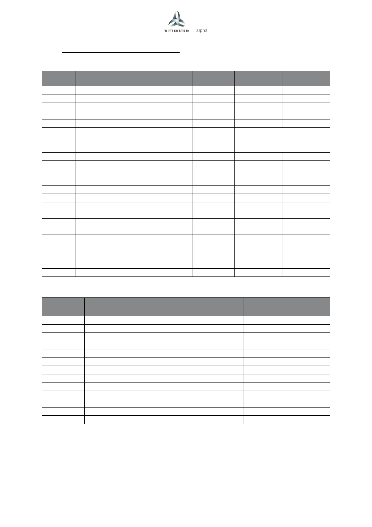
Code
Description
Unit i=4-35
i=40-100
Ratio
Motor inertia
Motor inertia
I
I
Quick Startup Guide TPM+
4.9 Parameter TPM+ Power 004 560V
Exceute “Complete calculation without equiv. circuit diag. data” after input.
560 VDC
560 VDC
p305 Rated motor current Arms 1,56 1,00
p311 Rated motor velocity rpm 5000 5000
p314 Motor pole pair number - 4 4
p316 Motor torque constant Nm/Arms 0,97 0,78
p322 Maximum motor speed rpm 6000 6000
p323 Maximum motor current Arms See table below
p338 Motor limit current Arms See table below
p341 Motor moment of inertia kgm² See table below
p350 Motor stator resistance, cold Ohm 10,65 20,00
p356 Motor stator leakage inductance mH 11,40 15,00
p312 Rated motor torque Nm 1,25 0,66
p317 Motor voltage constant Volt 58,5 47,4
p318 Motor stall current Arms 1,56 1,00
p319 Motor stall torque Nm 1,25 0,66
Current controller adaptation,
p391
lower starting point Arms 1,6 1,0
Current controller adaptation,
p392
upper starting point Arms 5,2 3,0
Current controller adaptation,
p393
P gain, scaling upper % 75 81
p1215 1 Motor holding brake configuration - 1 1
p1216 Motor holding brake opening time ms 12 12
p1217 Motor holding brake closing time ms 10 10
1
For actuators without holding brake the parameter p1215 has to be set to 0.
w/o brake[kgm²]
with brake[kgm²]
max_stat
[A
rms
]2
max_dyn
[A
rms
]3
4 0,000039 0,000041 5,20 5,20
5 0,000036 0,000038 5,20 5,20
7 0,000033 0,000035 5,20 5,20
10 0,000031 0,000034 3,60 5,20
16 0,000032 0,000034 4,40 5,20
20 0,000031 0,000034 3,50 5,20
25 0,000031 0,000034 2,80 5,20
28 0,000031 0,000033 2,50 5,20
35 0,000031 0,000033 1,90 5,20
40 0,000016 0,000018 2,10 3,00
50 0,000016 0,000018 1,70 3,00
70 0,000016 0,000018 1,20 3,00
100 0,000016 0,000018 0,60 3,00
2
Static maximum motorcurrent: Use this maximum current to protect the gear reducer from overload
and to reduce the torque safely to T2B.
3
Dynamic maximum motorcurrent: For dynamic applications the maximum current can be increased
to this value in dependency of the mass moment of inertia relation. We recommend a detailed
calculation with Cymex.
Page en-15
Revision: 02 4091- D032124 Date: 27th March 2017
Page 17
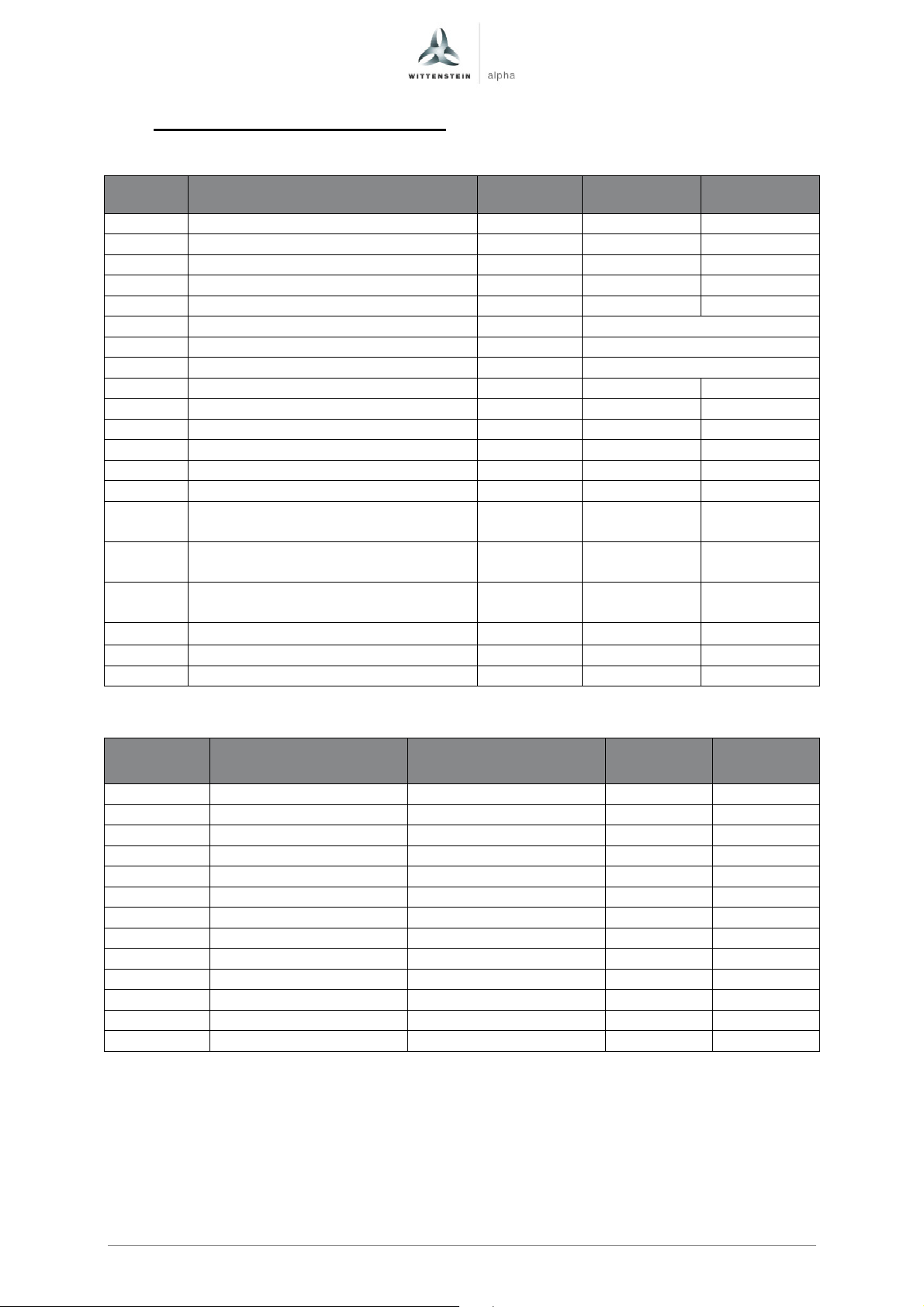
Code
Description
Unit i=4-35
i=40-100
Ratio
Motor inertia
Motor inertia
I
I
TPM+ Quick Startup Guide
4.10 Parameter TPM+ Power 010 560V
Exceute “Complete calculation without equiv. circuit diag. data” after input.
560 VDC
560 VDC
p305 Rated motor current Arms 5,40 1,86
p311 Rated motor velocity rpm 5000 5000
p314 Motor pole pair number - 6 6
p316 Motor torque constant Nm/Arms 0,98 1,02
p322 Maximum motor speed rpm 6000 6000
p323 Maximum motor current Arms See table below
p338 Motor limit current Arms See table below
p341 Motor moment of inertia kgm² See table below
p350 Motor stator resistance, cold Ohm 1,10 6,75
p356 Motor stator leakage inductance mH 3,00 9,45
p312 Rated motor torque Nm 4,50 1,38
p317 Motor voltage constant Volt 59,5 61,3
p318 Motor stall current Arms 5,40 1,86
p319 Motor stall torque Nm 4,50 1,38
Current controller adaptation,
p391
lower starting point Arms 5,4 1,9
Current controller adaptation,
p392
upper starting point Arms 17,0 6,0
Current controller adaptation,
p393
P gain, scaling upper % 73 72
p1215 1 Motor holding brake configuration - 1 1
p1216 Motor holding brake opening time ms 30 30
p1217 Motor holding brake closing time ms 20 20
1
For actuators without holding brake the parameter p1215 has to be set to 0.
w/o brake[kgm²]
with brake[kgm²]
max_stat
[A
rms
]2
max_dyn
[A
rms
]3
4 0,000238 0,000257 17,00 17,00
5 0,000222 0,000241 17,00 17,00
7 0,000208 0,000227 17,00 17,00
10 0,000200 0,000219 12,20 17,00
16 0,000202 0,000221 11,50 17,00
20 0,000199 0,000218 8,90 17,00
25 0,000198 0,000217 6,90 17,00
28 0,000196 0,000215 6,00 17,00
35 0,000196 0,000214 4,70 17,00
40 0,000072 0,000091 4,70 6,00
50 0,000072 0,000091 3,70 6,00
70 0,000072 0,000091 2,70 6,00
100 0,000072 0,000091 1,50 6,00
2
Static maximum motorcurrent: Use this maximum current to protect the gear reducer from overload
and to reduce the torque safely to T2B.
3
Dynamic maximum motorcurrent: For dynamic applications the maximum current can be increased
to this value in dependency of the mass moment of inertia relation. We recommend a detailed
calculation with Cymex.
Page en-16
Revision: 02 4091-D032124 Date: 27th March 2017
Page 18
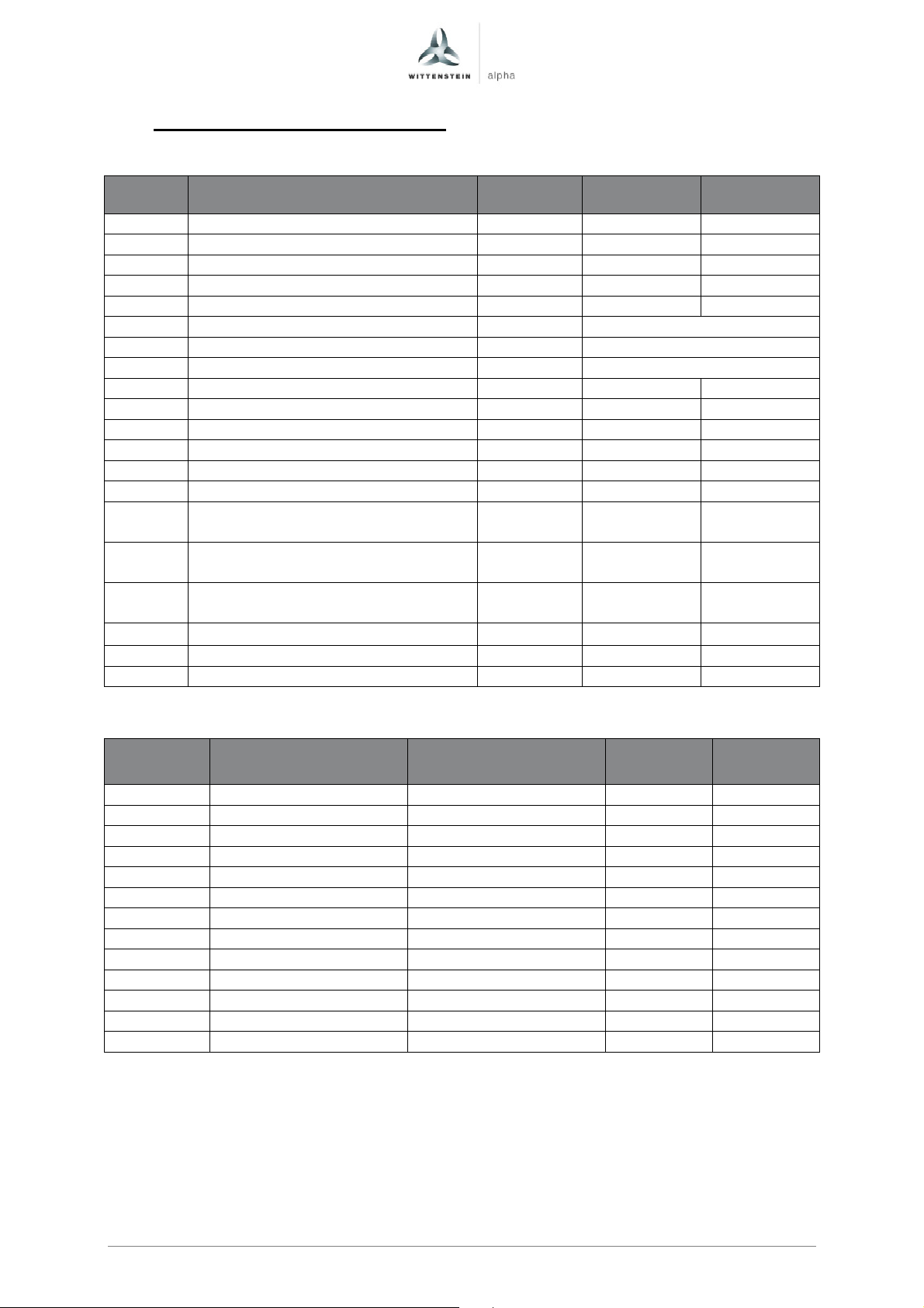
Code
Description
Unit i=4-35
i=40-100
Ratio
Motor inertia
Motor inertia
I
I
Quick Startup Guide TPM+
4.11 Parameter TPM+ Power 025 560V
Exceute “Complete calculation without equiv. circuit diag. data” after input.
560 VDC
560 VDC
p305 Rated motor current Arms 13,70 4,00
p311 Rated motor velocity rpm 5000 5000
p314 Motor pole pair number - 6 6
p316 Motor torque constant Nm/Arms 1,00 0,97
p322 Maximum motor speed rpm 6000 6000
p323 Maximum motor current Arms See table below
p338 Motor limit current Arms See table below
p341 Motor moment of inertia kgm² See table below
p350 Motor stator resistance, cold Ohm 0,22 2,00
p356 Motor stator leakage inductance mH 1,50 5,55
p312 Rated motor torque Nm 11,68 3,00
p317 Motor voltage constant Volt 61,0 58,7
p318 Motor stall current Arms 13,70 4,00
p319 Motor stall torque Nm 11,68 3,00
Current controller adaptation,
p391
lower starting point Arms 13,7 4,0
Current controller adaptation,
p392
upper starting point Arms 40,0 12,0
Current controller adaptation,
p393
P gain, scaling upper % 72 67
p1215 1 Motor holding brake configuration - 1 1
p1216 Motor holding brake opening time ms 42 42
p1217 Motor holding brake closing time ms 20 20
1
For actuators without holding brake the parameter p1215 has to be set to 0.
w/o brake[kgm²]
with brake[kgm²]
max_stat
[A
rms
]2
max_dyn
[A
rms
]3
4 0,000998 0,001098 40,00 40,00
5 0,000950 0,001050 40,00 40,00
7 0,000907 0,001007 40,00 40,00
10 0,000884 0,000984 27,00 40,00
16 0,000894 0,000994 29,90 40,00
20 0,000883 0,000982 23,10 40,00
25 0,000881 0,000980 19,50 40,00
28 0,000872 0,000972 15,30 40,00
35 0,000871 0,000971 13,00 40,00
40 0,000248 0,000348 12,00 12,00
50 0,000248 0,000348 12,00 12,00
70 0,000248 0,000347 7,10 12,00
100 0,000247 0,000347 3,70 12,00
2
Static maximum motorcurrent: Use this maximum current to protect the gear reducer from overload
and to reduce the torque safely to T2B.
3
Dynamic maximum motorcurrent: For dynamic applications the maximum current can be increased
to this value in dependency of the mass moment of inertia relation. We recommend a detailed
calculation with Cymex.
Page en-17
Revision: 02 4091- D032124 Date: 27th March 2017
Page 19
Code
Description
Unit i=4-35
i=40-100
Ratio
Motor inertia
Motor inertia
I
I
TPM+ Quick Startup Guide
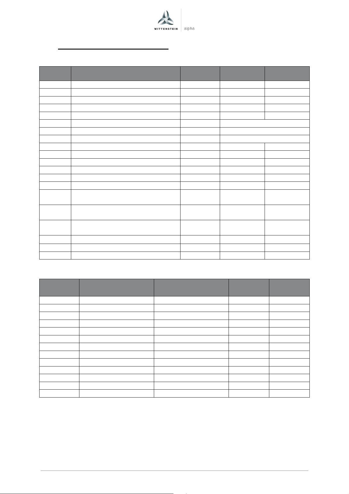
4.12 Parameter TPM+ Power 050 560V
Exceute “Complete calculation without equiv. circuit diag. data” after input.
560 VDC
560 VDC
p305 Rated motor current Arms 19,00 7,50
p311 Rated motor velocity rpm 4167 4167
p314 Motor pole pair number - 6 6
p316 Motor torque constant Nm/Arms 1,19 0,91
p322 Maximum motor speed rpm 5000 5000
p323 Maximum motor current Arms See table below
p338 Motor limit current Arms See table below
p341 Motor moment of inertia kgm² See table below
p350 Motor stator resistance, cold Ohm 0,14 0,90
p356 Motor stator leakage inductance mH 1,05 2,55
p312 Rated motor torque Nm 19,30 5,40
p317 Motor voltage constant Volt 71,9 55,1
p318 Motor stall current Arms 19,00 7,50
p319 Motor stall torque Nm 19,30 5,40
Current controller adaptation,
p391
lower starting point Arms 19,0 7,5
Current controller adaptation,
p392
upper starting point Arms 63,5 33,0
Current controller adaptation,
p393
P gain, scaling upper % 75 52
p1215 1 Motor holding brake configuration - 1 1
p1216 Motor holding brake opening time ms 50 50
p1217 Motor holding brake closing time ms 40 40
1
For actuators without holding brake the parameter p1215 has to be set to 0.
w/o brake[kgm²]
with brake[kgm²]
max_stat
[A
rms
]2
max_dyn
[A
rms
]3
4 0,002642 0,002822 63,50 63,50
5 0,002480 0,002660 63,50 63,50
7 0,002334 0,002514 54,90 63,50
10 0,002254 0,002434 38,40 63,50
16 0,002307 0,002487 53,10 63,50
20 0,002261 0,002441 41,70 63,50
25 0,002255 0,002435 32,60 63,50
28 0,002220 0,002400 28,60 63,50
35 0,002217 0,002397 22,20 63,50
40 0,00063 0,00081 33,00 33,00
50 0,000628 0,000808 32,50 33,00
70 0,000627 0,000807 19,90 33,00
100 0,000626 0,000806 8,30 33,00
2
Static maximum motorcurrent: Use this maximum current to protect the gear reducer from overload
and to reduce the torque safely to T2B.
3
Dynamic maximum motorcurrent: For dynamic applications the maximum current can be increased
to this value in dependency of the mass moment of inertia relation. We recommend a detailed
calculation with Cymex.
Page en-18
Revision: 02 4091-D032124 Date: 27th March 2017
Page 20
Code
Description
Unit i=4-35
i=40-100
Ratio
Motor inertia
Motor inertia
I
I
Quick Startup Guide TPM+
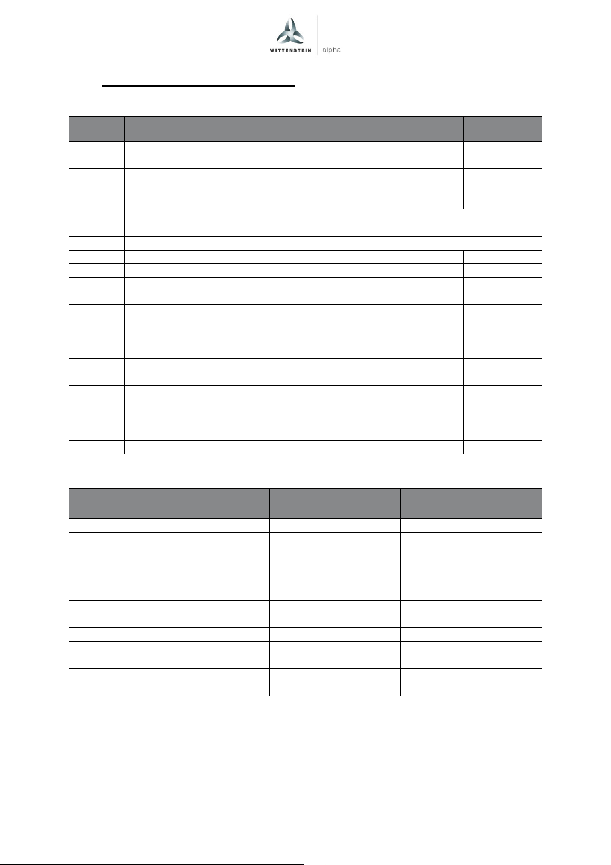
4.13 Parameter TPM+ Power 110 560V
Exceute “Complete calculation without equiv. circuit diag. data” after input.
560 VDC
560 VDC
p305 Rated motor current Arms 38,60 21,90
p311 Rated motor velocity rpm 3500 3750
p314 Motor pole pair number - 6 6
p316 Motor torque constant Nm/Arms 1,09 1,08
p322 Maximum motor speed rpm 4200 4500
p323 Maximum motor current Arms See table below
p338 Motor limit current Arms See table below
p341 Motor moment of inertia kgm² See table below
p350 Motor stator resistance, cold Ohm 0,04 0,12
p356 Motor stator leakage inductance mH 0,45 0,95
p312 Rated motor torque Nm 36,90 20,74
p317 Motor voltage constant Volt 66,1 65,3
p318 Motor stall current Arms 38,60 21,90
p319 Motor stall torque Nm 36,90 20,74
Current controller adaptation,
p391
lower starting point Arms 38,6 21,9
Current controller adaptation,
p392
upper starting point Arms 100,0 50,0
Current controller adaptation,
p393
P gain, scaling upper % 81 82
p1215 1 Motor holding brake configuration - 1 1
p1216 Motor holding brake opening time ms 200 200
p1217 Motor holding brake closing time ms 50 50
1
For actuators without holding brake the parameter p1215 has to be set to 0.
w/o brake[kgm²]
with brake[kgm²]
max_stat
[A
rms
]2
max_dyn
[A
rms
]3
4 0,014173 0,015873 100,00 100,00
5 0,013191 0,014891 100,00 100,00
7 0,012300 0,014000 100,00 100,00
10 0,011812 0,013512 62,60 100,00
16 0,011699 0,013399 100,00 100,00
20 0,011670 0,013370 92,40 100,00
25 0,011630 0,013330 72,90 100,00
28 0,011505 0,013205 64,40 100,00
35 0,011485 0,013185 50,50 100,00
40 0,006023 0,007723 46,00 50,00
50 0,006013 0,007713 36,30 50,00
70 0,006004 0,007704 25,30 50,00
100 0,005999 0,007699 15,50 50,00
2
Static maximum motorcurrent: Use this maximum current to protect the gear reducer from overload
and to reduce the torque safely to T2B.
3
Dynamic maximum motorcurrent: For dynamic applications the maximum current can be increased
to this value in dependency of the mass moment of inertia relation. We recommend a detailed
calculation with Cymex.
Page en-19
Revision: 02 4091- D032124 Date: 27th March 2017
Page 21
Code
Description
Unit i=22-110
i=154
-
220
Ratio
Motor inertia
Motor inertia
I
I
TPM+ Quick Startup Guide
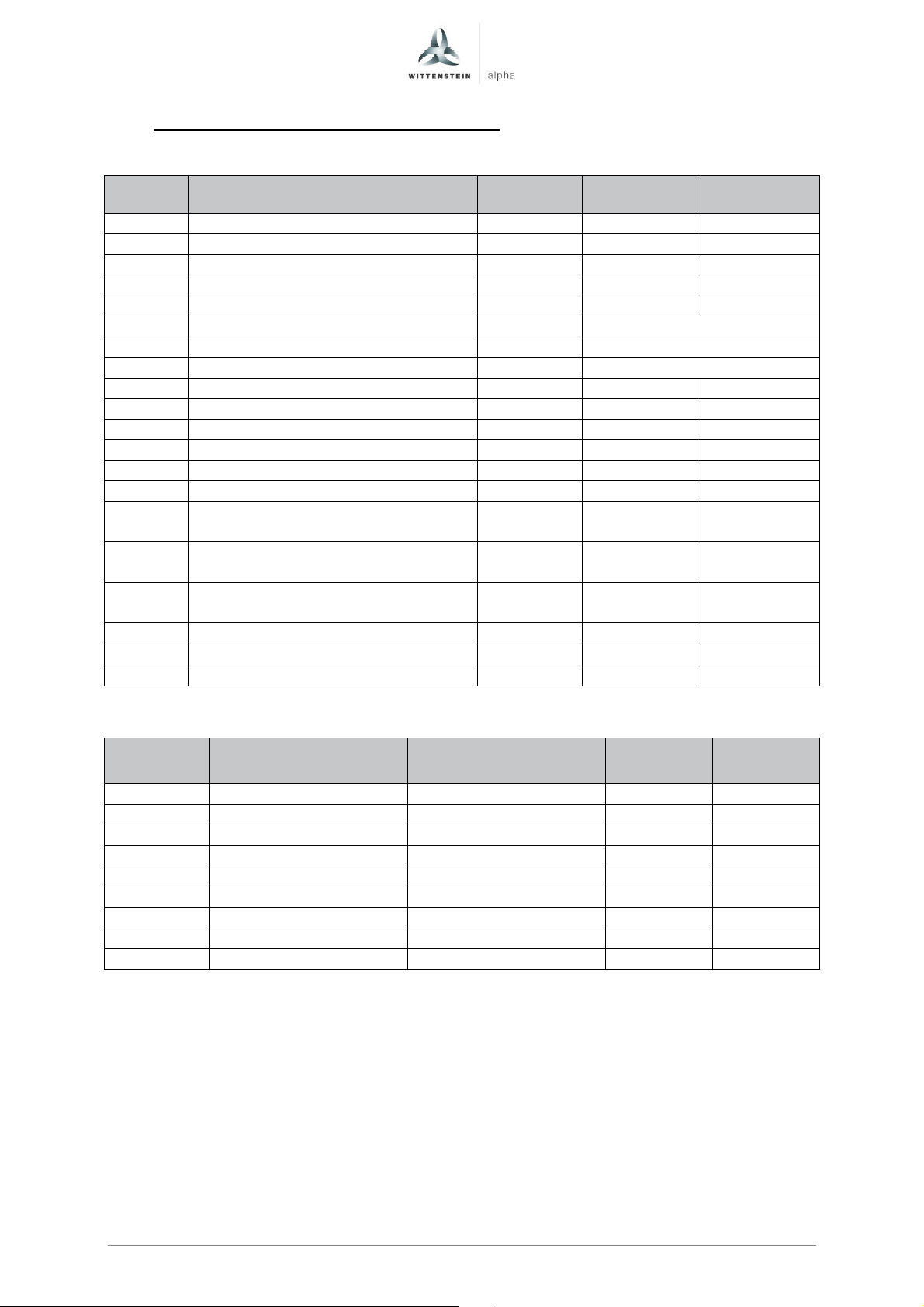
4.14 Parameter TPM+ High Torque 010 560V
Exceute “Complete calculation without equiv. circuit diag. data” after input.
560 VDC
560 VDC
p305 Rated motor current Arms 4,99 1,92
p311 Rated motor velocity rpm 4042 4042
p314 Motor pole pair number - 6 6
p316 Motor torque constant Nm/Arms 0,83 0,82
p322 Maximum motor speed rpm 4850 4850
p323 Maximum motor current Arms See table below
p338 Motor limit current Arms See table below
p341 Motor moment of inertia kgm² See table below
p350 Motor stator resistance, cold Ohm 1,18 7,85
p356 Motor stator leakage inductance mH 3,00 9,45
p312 Rated motor torque Nm 3,75 1,44
p317 Motor voltage constant Volt 50,3 49,2
p318 Motor stall current Arms 4,99 1,92
p319 Motor stall torque Nm 3,75 1,44
Current controller adaptation,
p391
lower starting point Arms 5,0 1,9
Current controller adaptation,
p392
upper starting point Arms 17,0 6,0
Current controller adaptation,
p393
P gain, scaling upper % 85 89
p1215 1 Motor holding brake configuration - 1 1
p1216 Motor holding brake opening time ms 30 30
p1217 Motor holding brake closing time ms 20 25
1
For actuators without holding brake the parameter p1215 has to be set to 0.
w/o brake[kgm²]
with brake[kgm²]
max_stat
[A
rms
]2
max_dyn
[A
rms
]3
22 0,000206 0,000225 15,00 17,00
27,5 0,000203 0,000222 11,90 17,00
38,5 0,000201 0,000220 8,40 17,00
55 0,000199 0,000218 5,80 17,00
66 - - - -
88 0,000201 0,000220 3,70 17,00
110 0,000200 0,000219 3,00 17,00
154 0,000068 0,000087 2,20 6,00
220 0,000067 0,000086 1,60 6,00
2
Static maximum motorcurrent: Use this maximum current to protect the gear reducer from overload
and to reduce the torque safely to T2B.
3
Dynamic maximum motorcurrent: For dynamic applications the maximum current can be increased
to this value in dependency of the mass moment of inertia relation. We recommend a detailed
calculation with Cymex.
Page en-20
Revision: 02 4091-D032124 Date: 27th March 2017
Page 22
Code
Description
Unit i=22-55
i=66-220
Ratio
Motor inertia
Motor inertia
I
I
Quick Startup Guide TPM+
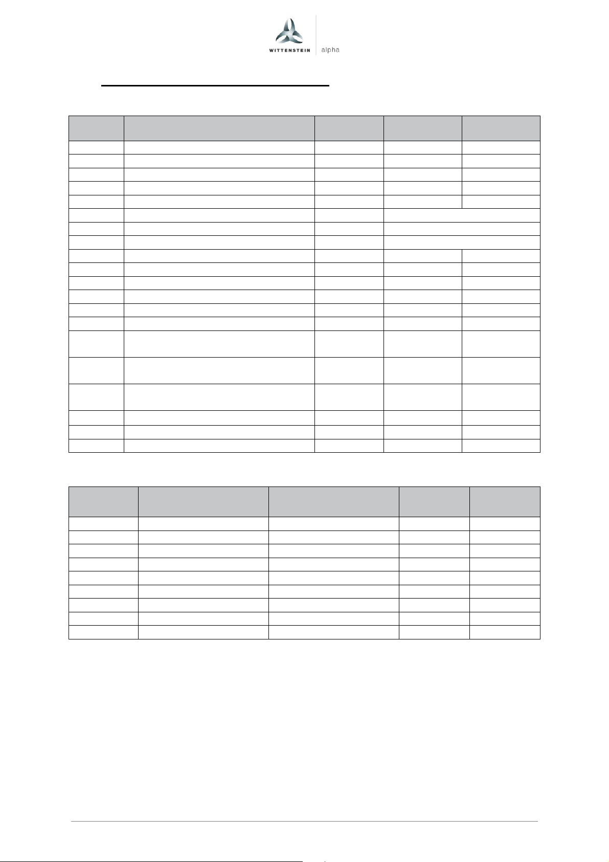
4.15 Parameter TPM+ High Torque 025 560V
Exceute “Complete calculation without equiv. circuit diag. data” after input.
560 VDC
560 VDC
p305 Rated motor current Arms 13,08 5,76
p311 Rated motor velocity rpm 4042 4042
p314 Motor pole pair number - 6 6
p316 Motor torque constant Nm/Arms 0,98 0,83
p322 Maximum motor speed rpm 4850 4850
p323 Maximum motor current Arms See table below
p338 Motor limit current Arms See table below
p341 Motor moment of inertia kgm² See table below
p350 Motor stator resistance, cold Ohm 0,24 1,18
p356 Motor stator leakage inductance mH 1,50 3,00
p312 Rated motor torque Nm 10,92 4,19
p317 Motor voltage constant Volt 59,2 50,3
p318 Motor stall current Arms 13,08 5,76
p319 Motor stall torque Nm 10,92 4,19
Current controller adaptation,
p391
lower starting point Arms 13,1 5,8
Current controller adaptation,
p392
upper starting point Arms 40,0 17,0
Current controller adaptation,
p393
P gain, scaling upper % 74 85
p1215 1 Motor holding brake configuration - 1 1
p1216 Motor holding brake opening time ms 42 30
p1217 Motor holding brake closing time ms 20 20
1
For actuators without holding brake the parameter p1215 has to be set to 0.
w/o brake[kgm²]
with brake[kgm²]
max_stat
[A
rms
]2
max_dyn
[A
rms
]3
22 0,000901 0,001000 33,40 40,00
27,5 0,000883 0,000983 26,10 40,00
38,5 0,000874 0,000974 17,80 40,00
55 0,000869 0,000969 11,80 40,00
66 0,000203 0,000222 10,50 17,00
88 0,000196 0,000215 7,80 17,00
110 0,000193 0,000212 6,20 17,00
154 0,000191 0,000210 4,40 17,00
220 0,000189 0,000208 3,10 17,00
2
Static maximum motorcurrent: Use this maximum current to protect the gear reducer from overload
and to reduce the torque safely to T2B.
3
Dynamic maximum motorcurrent: For dynamic applications the maximum current can be increased
to this value in dependency of the mass moment of inertia relation. We recommend a detailed
calculation with Cymex.
Page en-21
Revision: 02 4091- D032124 Date: 27th March 2017
Page 23
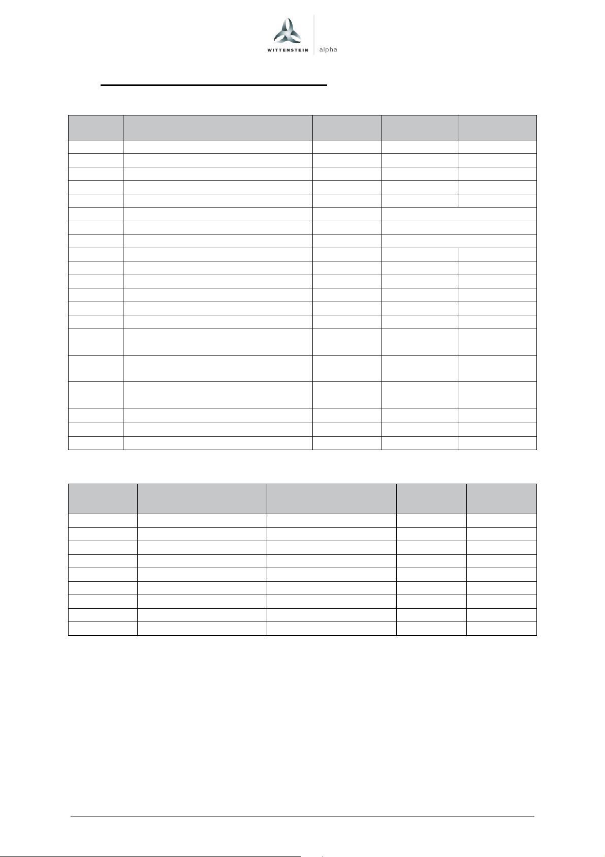
Code
Description
Unit i=22-55
i=66-220
Ratio
Motor inertia
Motor inertia
I
I
TPM+ Quick Startup Guide
4.16 Parameter TPM+ High Torque 050 560V
Exceute “Complete calculation without equiv. circuit diag. data” after input.
560 VDC
560 VDC
p305 Rated motor current Arms 17,93 12,60
p311 Rated motor velocity rpm 3750 4042
p314 Motor pole pair number - 6 6
p316 Motor torque constant Nm/Arms 1,21 1,00
p322 Maximum motor speed rpm 4500 4850
p323 Maximum motor current Arms See table below
p338 Motor limit current Arms See table below
p341 Motor moment of inertia kgm² See table below
p350 Motor stator resistance, cold Ohm 0,14 0,24
p356 Motor stator leakage inductance mH 1,05 1,50
p312 Rated motor torque Nm 19,28 11,11
p317 Motor voltage constant Volt 73,4 61,0
p318 Motor stall current Arms 17,93 12,60
p319 Motor stall torque Nm 19,28 11,11
Current controller adaptation,
p391
lower starting point Arms 17,9 12,6
Current controller adaptation,
p392
upper starting point Arms 63,5 40,0
Current controller adaptation,
p393
P gain, scaling upper % 74 72
p1215 1 Motor holding brake configuration - 1 1
p1216 Motor holding brake opening time ms 50 42
p1217 Motor holding brake closing time ms 40 20
1
For actuators without holding brake the parameter p1215 has to be set to 0.
w/o brake[kgm²]
with brake[kgm²]
max_stat
[A
rms
]2
max_dyn
[A
rms
]3
22 0,002380 0,002560 48,10 63,50
27,5 0,002335 0,002515 37,30 63,50
38,5 0,002299 0,002479 25,10 63,50
55 0,002281 0,002461 16,40 63,50
66 0,000923 0,001022 18,20 40,00
88 0,000904 0,001003 12,50 40,00
110 0,000884 0,000983 10,10 40,00
154 0,000874 0,000974 7,20 40,00
220 0,000869 0,000969 5,00 40,00
2
Static maximum motorcurrent: Use this maximum current to protect the gear reducer from overload
and to reduce the torque safely to T2B.
3
Dynamic maximum motorcurrent: For dynamic applications the maximum current can be increased
to this value in dependency of the mass moment of inertia relation. We recommend a detailed
calculation with Cymex.
Page en-22
Revision: 02 4091-D032124 Date: 27th March 2017
Page 24

Code
Description
Unit i=22-55
i=66-88
i=110
-
220
Ratio
Motor inertia
Motor inertia
I
I
Quick Startup Guide TPM+
4.17 Parameter TPM+ High Torque 110 560V
Exceute “Complete calculation without equiv. circuit diag. data” after input.
560 VDC
560 VDC
560 VDC
p305 Rated motor current Arms Tbd 40,85 20,50
p311 Rated motor velocity rpm 3458 3458 3750
p314 Motor pole pair number - 6 6 6
p316 Motor torque constant Nm/Arms 1,17 1,09 1,19
p322 Maximum motor speed rpm 4150 4150 4500
p323 Maximum motor current Arms See table below
p338 Motor limit current Arms See table below
p341 Motor moment of inertia kgm² See table below
p350 Motor stator resistance, cold Ohm 0,02 0,04 0,14
p356 Motor stator leakage inductance mH 0,34 0,45 1,05
p312 Rated motor torque Nm tbd 40,35 22,18
p317 Motor voltage constant Volt 70,9 66,1 71,9
p318 Motor stall current Arms tbd 40,85 20,50
p319 Motor stall torque Nm tbd 40,35 22,18
Current controller adaptation,
p391
lower starting point Arms 53,7 40,8 20,5
Current controller adaptation,
p392
upper starting point Arms 160,0 100,0 63,5
Current controller adaptation,
p393
P gain, scaling upper % 88 81 75
p1215 1 Motor holding brake configuration - 1 1 1
p1216 Motor holding brake opening time ms 200 200 50
p1217 Motor holding brake closing time ms 50 50 40
1
For actuators without holding brake the parameter p1215 has to be set to 0.
w/o brake[kgm²]
with brake[kgm²]
max_stat
[A
rms
]2
max_dyn
[A
rms
]3
22 0,022037 0,023687 tbd tbd
27,5 0,021891 0,023541 tbd tbd
38,5 0,021763 0,023413 tbd tbd
55 0,021694 0,023344 tbd tbd
66 0,011182 0,012882 40,50 100,00
88 0,010824 0,012524 30,40 100,00
110 0,002286 0,002466 23,00 63,50
154 0,002248 0,002428 15,90 63,50
220 0,002225 0,002405 11,20 63,50
2
Static maximum motorcurrent: Use this maximum current to protect the gear reducer from overload
and to reduce the torque safely to T2B.
3
Dynamic maximum motorcurrent: For dynamic applications the maximum current can be increased
to this value in dependency of the mass moment of inertia relation. We recommend a detailed
calculation with Cymex.
Page en-23
Revision: 02 4091- D032124 Date: 27th March 2017
Page 25
TPM+ Quick Startup Guide
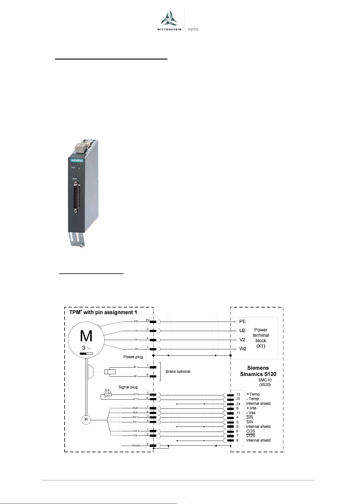
5 Connection schematic TPM+
Detailed information on cable design and the type of shielding can be found in the
documentation from the servo drive manufacturer.
When using the cables from Wittenstein alpha a connector from Siemens is
required to connect the cable to the Sinamics power module.
To connect the motor feedback to the Siemens DRIVE-CLiQ bus the
SMC10(Siemens article 6SL3055-0AA00-5AA3) for Resolver resp. the
SMC20(Siemens article 6SL3055-0AA00-5BA3) for absolute EnDat or incremental
feedback is required.
5.1 TPM+ with resolver
WITTENSTEIN alpha offers pre-manufactured and drag chain compatible cablesets
for this servo drive. Please take the required order informations from the TPM+
catalogue.
Page en-24
Revision: 02 4091-D032124 Date: 27th March 2017
Page 26
Quick Startup Guide TPM+
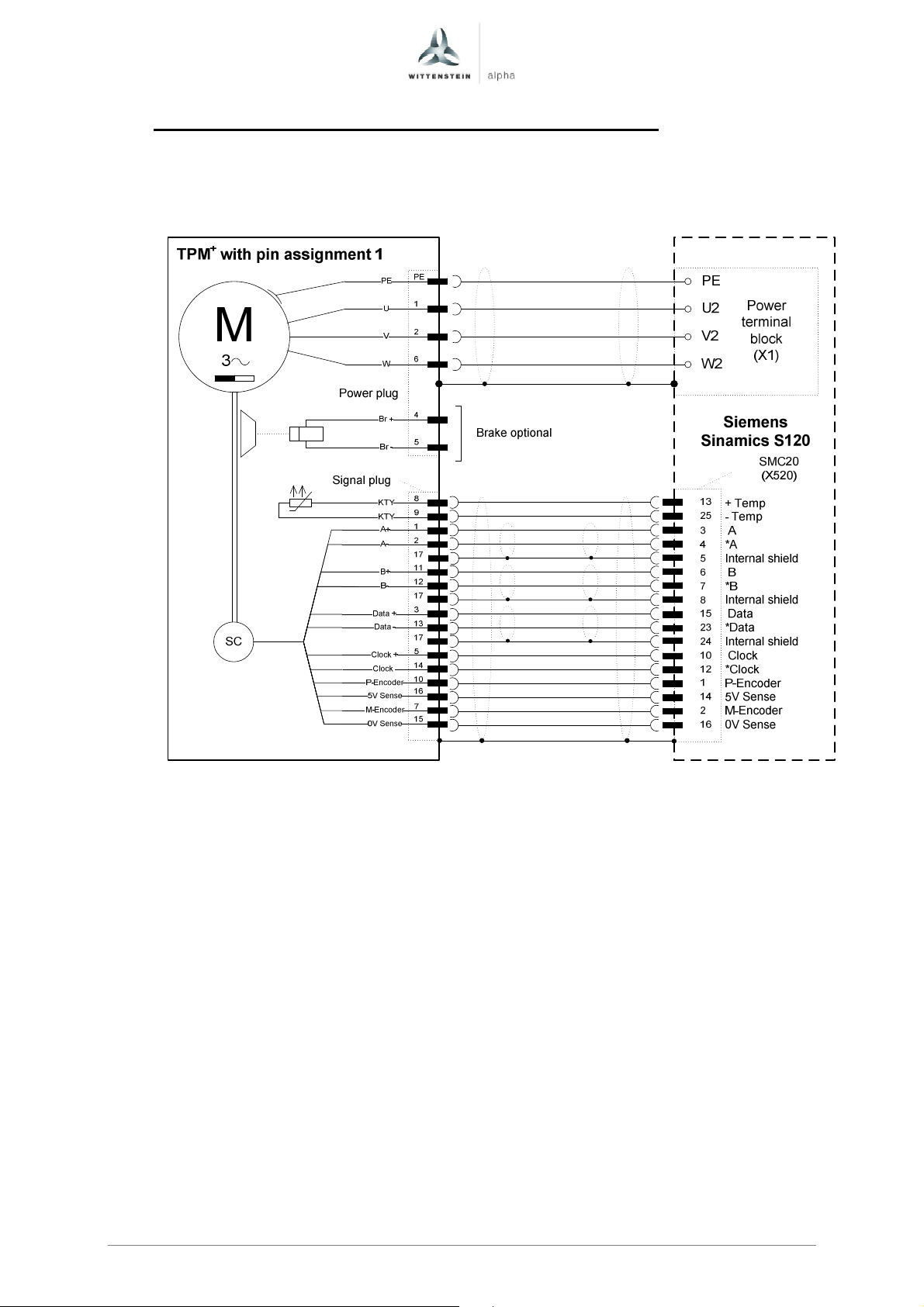
5.2 TPM+ with absolute encoder Heidenhain EnDat EQN 1125
WITTENSTEIN alpha offers pre-manufactured and drag chain compatible cablesets
for this servo drive. Please take the required order informations from the TPM+
catalogue.
Page en-25
Revision: 02 4091- D032124 Date: 27th March 2017
Page 27
TPM+ Quick Startup Guide
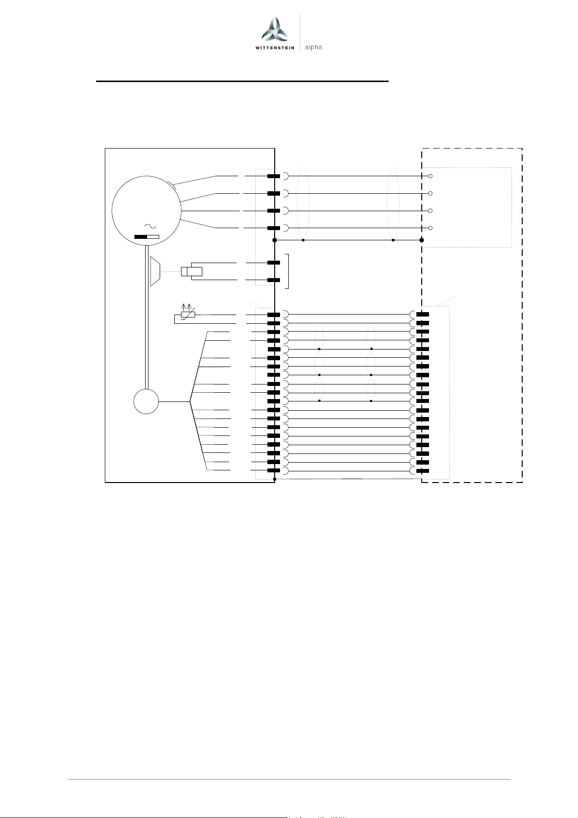
5.3 TPM+ with incremental encoder Heidenhain ERN1185
WITTENSTEIN alpha offers pre-manufactured and drag chain compatible cablesets
for this servo drive. Please take the required order informations from the TPM+
catalogue.
TPM+with pin assignment 1
PE
M
3
PE
1
U
2
V
6
W
PE
U2
V2
W2
Power
terminal
block
(X1)
Power plug
Br +
Br -
4
5
Brake optional
Siemens
Sinamics S120
SMC20
(X520)
+ Temp
- Temp
A
*A
Internal shield
B
*B
Internal shield
R
*R
Internal shield
C
*C
P-Encoder
5V Sense
M-Encoder
0V Sense
D
*D
SC
Signal plug
KTY
KTY
A+ / Ua1+
A- / Ua1-
B+ / Ua2+
B- / Ua2-
R+ / Ua0+
R- / Ua0-
C+ / Ua3+
C- / Ua3-
P-Encoder
5V Sense
M-Encoder
0V Sense
D+ / Ua4+
D- / Ua4-
8
9
1
2
17
11
12
17
3
13
17
5
6
10
16
7
15
14
4
13
25
3
4
5
6
7
8
17
18
24
19
20
1
14
2
16
21
22
Page en-26
Revision: 02 4091-D032124 Date: 27th March 2017
Page 28
2022-D016962
:
01
enAC: XXXXXXXX 2022-D016962 Revision: 01
WITTENSTEIN alpha GmbH · Walter-Wittenstein-Straße 1 · 97999 Igersheim · Germany
Tel. +49 7931 493-12900 · [email protected]
WITTENSTEIN - one with the future
www.wittenstein-alpha.de
 Loading...