

Witt HR 1, HR 3, HS 30, HR 4, HS 40 Installation And Operating Instructions Manual [de, en]
...Page 1
HochdruckschwimmerRegler
Montage- und
Betriebsanleitung
High side float
regulator
Installation- and operating
instructions
HR/HS
Page 2
Montage- und Betriebsanleitung
HR / HS
operation and service manual
2
Page 3

MONTAGE- UND BETRIEBSANLEITUNG
INHALTSVERZEICHNIS CONTENTS
1. EINLEITUNG............................................................................ 4
1.1 VERWENDUNGSZWECK.............................................. 4
1.2 SICHERHEITSBESTIMMUNGEN .................................. 4
1.3 HAFTUNGSAUSSCHLUß.............................................. 4
HR / HS
1. INTRODUCION .........................................................................4
1.1 INTENDED USE .............................................................4
1.2 SAFETY REQUIREMENTS.............................................4
1.3 MANUFACTURER DISCLAIMER....................................4
OPERATION & SERVICE MANUAL
2. GEWÄHRLEISTUNGSBESTIMMUNGEN................................ 5
3. TECHNISCHE INFORMATION................................................. 5
3.1 TYPENBEZEICHNUNG ................................................. 5
3.2 LIEFERUMFANG........................................................... 6
3.3 ABNAHMEN/BESCHEINIGUNGEN ............................... 7
3.4 BESTELLANGABEN...................................................... 8
3.5 STEUEREINHEIT .......................................................... 9
4. TECHNISCHE DATEN ............................................................11
4.1 MATERIALIEN ..............................................................11
4.2 DRUCK/TEMPERATUR BEREICHE.............................11
4.3 ÜBERBLICK..................................................................12
4.4 ABMESSUNGEN ..........................................................17
4.5 GEÄNDERTE VENTILSTELLUNGEN...........................22
5. FUNKTIONSBESCHREIBUNG...............................................24
5.1 FUNKTION INNERHALB DER ANLAGE.......................24
5.2 SCHWIMMER-REGELUNG ..........................................27
5.3 FUNKTION DER UNTERDRUCKDÜSE........................27
6. PLANUNGSHINWEISE...........................................................30
6.1 ALLGEMEINES.............................................................30
6.2 AUSWAHLKRITERIEN .................................................30
6.3 ANORDNUNG...............................................................30
6.4 ZULAUFLEITUNG.........................................................33
6.5 EINSPRITZLEITUNG....................................................34
7. TRANSPORT UND LAGERUNG.............................................35
2. TERMS OF WARRENTY...........................................................5
3. TECHNICAL INFORMATION....................................................5
3.1 DESCRIPTION OF TYPES:............................................5
3.2 SCOPE OF DELIVERY...................................................6
3.3 INSPECTIONS/CERTIFICATES .....................................7
3.4 ORDERINFORMATION ..................................................8
3.5 CONTROL UNIT.............................................................9
4. TECHNICAL DATA .................................................................11
4.1 MATERIALS..................................................................11
4.2 PRESSURE/TEMPERATURE RANGE.........................11
4.3 OVERVIEW...................................................................12
4.4 DIMENSIONS ...............................................................17
4.5 MODIFIED VALVE POSITIONS....................................22
5. DESCRIPTION OF OPERATION ............................................24
5.1 OPERATION WITHIN THE PLANT...............................24
5.2 FLOAT REGULATION ..................................................27
5.3 FUNCTION OF THE LOW PRESSURE NOZZLE .........27
6. HINTS FOR PLANNING..........................................................30
6.1 GENERAL.....................................................................30
6.2 SELECTION CRITERIA................................................30
6.3 LOCATION ...................................................................30
6.4 LIQUID FEED LINE.......................................................33
6.5 LOW PRESSURE LINE FROM THE REGULATOR ......34
7. TRANSPORT AND STORAGE ...............................................35
8. MONTAGE .............................................................................35
8.1 MONTAGEVORBEREITUNG........................................35
8.2 MONTAGEANLEITUNG................................................36
9. INBETRIEBNAHME ................................................................36
9.1 VORBEREITUNG DER INBETRIEBNAHME.................36
9.2 INBETRIEBNAHME ......................................................37
10. BETRIEB.................................................................................37
11. WARTUNG UND INSTANDHALTUNG....................................37
11.1
11.2
11.3
11.4
11.5
11.6
12. FEHLERSUCHE......................................................................41
12.1
12.2
12.3
12.4
12.5
12.6
12.7
FUNKTIONSKONTROLLE.......................................37
AUSTAUSCH DES SCHWIMMKÖRPERS...............37
AUSTAUSCH DER HEBELPACKUNG ....................39
AUSTAUSCH DER VENTILPACKUNG....................40
ENTLÜFTUNG.........................................................40
ERWEITERUNG DER UNTERDRUCKDÜSE..........41
LUFT IN DER KÄLTEANLAGE ................................42
GASBILDUNG IN DER ZULAUFLEITUNG...............42
PARALLELSCHALTUNG VON VERFLÜSSIGERN..42
LUFTGEKÜHLTE VERFLÜSSIGER.........................42
PLATTENVERFLÜSSIGER .....................................43
HD-SAMMELBEHÄLTER.........................................43
EINSATZ VON ÖLKÜHLERN ..................................43
Th. Witt Kältemaschinenfabrik GmbH
Lukasstrasse 32, D-52070 Aachen
Tel. +49-241-18208-0, Fax. +49-241-18208-49
http://www.TH-WITT.com, [email protected]
W3510-6.01d – 07/2010
8. INSTALLATION .....................................................................35
8.1 PREPARING FOR INSTALLATION ..............................35
8.2 FIXING INSTRUCTIONS ..............................................36
9. COMMISSIONING...................................................................36
9.1 PRIOR TO COMMISSIONING ......................................36
9.2 COMMISSIONING ........................................................37
10. OPERATION ...........................................................................37
11. SERVICE AND MAINTANANCE .............................................37
11.1
11.2
11.3
11.4
11.5
11.6
12. TROUBLE SHOOTING ...........................................................41
12.1
12.2
12.3
12.4
12.5
12.6
12.7
FUNCTIONING CHECK...........................................37
REPLACING THE FLOAT BALL..............................37
REPLACING THE LEVER PACKING.......................39
REPLACEMENT OF THE VALVE PACKING...........40
PURGING................................................................40
ENLARGING THE LOW PRESSURE NOZZLE .......41
AIR IN THE REGRIGERATION SYSTEM................42
GAS FORMATION IN THE LIQUID FEED LINE ......42
PARALLEL OPERATION OF CONDENSERS .........42
AIRCOOLED CONDENSER....................................42
PLATE TYPE CONDENSER....................................43
USE OF HP LIQIUD RECEIVERS ...........................43
USE OF OIL COOLERS ..........................................43
3
Page 4
Hochdruckschwimmer-Regler
High Pressure Float Regulator
Montage- und Betriebsanleitung
1. EINLEITUNG
Bitte lesen Sie die komplette Betriebsanleitung sorgfältig,
bevor Sie den Hochdruckschwimmer-Regler auswählen,
in Gebrauch nehmen oder Wartungsarbeiten durchführen.
1.1 VERWENDUNGSZWECK
Der WITT Hochdruckschwimmer-Regler darf ausschließlich in
Kälteanlagen eingesetzt werden, um verflüssigtes Kältemittel
von der Hochdruckseite auf die Niederdruckseite zu entspannen.
1.2 SICHERHEITSBESTIMMUNGEN
1.3 HAFTUNGSAUSSCHLUß
Auch bei bestimmungsgemäßer Verwendung können Gefahren für Leib und Leben des Benutzers oder Dritter bzw. Beeinträchtigungen der Maschine und anderer Sachwerte entstehen.
Übersetzungen werden nach bestem Wissen durchgeführt.
Eine irgendwie geartete Haftung für Übersetzungsfehler können wir nicht übernehmen.
Gegenüber Darstellungen und Angaben dieser Betriebsanleitung sind technische Änderungen, die zur Verbesserung des
Hochdruckschwimmer-Reglers notwendig werden, vorbehalten.
Sämtliche beschriebene Arbeiten an dem Hochdruckschwimmer-Regler dürfen nur von sachkundigem, im Umgang mit Kälteanlagen geschultem Personal durchgeführt werden, das die einschlägigen
Vorschriften zur Erstellung und Wartung von Kälteanlagen kennt. Auch die Sicherheitsvorschriften hinsichtlich des Umgangs mit Kältemittel sind zu beachten, insbesondere das Tragen der persönlichen
Schutzbekleidung und einer Schutzbrille.
Die auf dem Typenschild und den Zeichnungen angegebenen Temperatur- und Druckangaben dürfen
auf keinen Fall überschritten werden.
Wenn am Eintritts- und am Austrittsstutzen Absperrventile vorgesehen sind, so muss sichergestellt werden, dass die Ventile im Betrieb immer voll geöffnet
bleiben.
Achtung! Dem Inhalt dieser Betriebsanleitung ist
unbedingt Folge zu leisten! Abweichender Einsatz
schließt eine Haftung und Gewährleistung durch den
Hersteller aus!
Die örtlichen Vorschriften für Kälteanlagen und Umweltauflagen, insbesondere bei der Kältemittel- und
Kälteölentsorgung sind einzuhalten.
97/23/EG
1. INTRODUCION
Please read the entire manual careful before selecting, installing, commissioning or servicing the highpressure float regulators.
1.1 INTENDED USE
The WITT high-pressure float regulator is intended for
the use in refrigerant plants to expand liquid refrigerant
from the high pressure to the low-pressure side.
1.2 SAFETY REQUIREMENTS
1.3 MANUFACTURER DISCLAIMER
Even when the float regulator is used for the specified
intended purpose it cannot be totally excluded some
danger for the life of the user may exist in the installation
or system.
Translations are carried out to the best of our knowledge. We are unable to accept any liability for translation
errors.
We reserve the right to change descriptions, graphs or
other statements, which are required due to technical
development of the high-pressure float regulators.
HR/HS
Installation- and operating instructions
Any of the following specified procedures must
be carried out by trained and knowledgeable
personnel experienced in installation and service of refrigerant plants. All personnel must be
familiar with the National legal requirements
and safety regulations. All safety regulations
and codes of practice concerning the use of
refrigerants must be adhered to, with special
attention paid to protection clothing and wearing
of safety glasses.
Under no circumstances are the stated design
temperature- and pressure limitations on the
data plate to be exceeded!
When installing inlet and outlet valves please
ensure that the valves are fully open during
.
operation.
Important! The contents of this manual must
be adhered to. Deviation from the specified
conditions will make any claim for liability or
warranty void.
All local rules for operation of refrigeration systems and ecological requirements, especially
waste treatment of refrigerants and oils must be
complied with.
4
Page 5

2. GEWÄHRLEISTUNGSBESTIMMUNGEN
Zur Vermeidung von Unfällen dürfen an den Hochdruckschwimmer-Reglern weder Veränderungen noch Umbauten
vorgenommen werden, die durch die TH. WITT KÄLTEMASCHINENFABRIK GMBH nicht ausdrücklich schriftlich genehmigt worden sind.
Diese Betriebsanleitung enthält die international genormten
SI-Maßeinheiten.
Alle Angaben und Hinweise für die Bedienung und Instandhaltung dieser Hochdruckschwimmer-Regler erfolgen unter Berücksichtigung unserer bisherigen Erfahrungen und Erkenntnissen nach bestem Wissen.
Eine Haftung oder Gewährleistung ist ausgeschlossen,
wenn:
• die Hinweise und Anweisungen der Betriebsanleitung nicht
beachtet werden,
• die Hochdruckschwimmer-Regler einschließlich zugehöriger
Einrichtungen fehlerhaft bedient werden bzw. deren Handhabung nicht dem vorgeschriebenen Ablauf entspricht,
• die Hochdruckschwimmer-Regler entgegen ihrer Bestimmung zweckentfremdet genutzt werden,
• Schutzeinrichtungen nicht benutzt oder außer Funktion
gesetzt werden,
• Funktionsänderungen jeder Art ohne unsere schriftliche
Zustimmung durchgeführt werden,
• die einschlägigen Sicherheitsbestimmungen nicht beachtet
werden,
• die Hochdruckschwimmer-Regler unsachgemäß (zeitlich wie
auch in der Ausführung) gewartet werden.
• beim Austausch von Teilen bzw. für die Ersatzteilbeschaffung nicht die vom Hersteller freigegebenen Originalersatzteile verwendet werden.
3. TECHNISCHE INFORMATION
2. TERMS
In order to avoid accidents and ensure optimum performance, no modifications or conversions may be
carried out to the high-pressure float regulator without
the explicit written approval by TH.WITT KÄLTEMASCHINENFABRIK GMBH.
These instructions are based on internationally standardised SI units of measurements.
All data and information on the operation and maintenance of the float regulators are provided based on our
extensive experience and to the best of our technical
knowledge.
Our liability or warranty is excluded, if:
• The information and instructions in the operating
manual are ignored,
• The high-pressure float regulators including accesso-
ries are operated incorrectly or are not installed according to the instructions.
• The high-pressure float regulators are used for pur-
pose other than that for which it was designed.
• Safety devices fitted are not used or disconnected
• There have been modifications made to the high
pressure float regulator without the manufacturers
written approval
• The safety regulations are not adhered to
• The high-pressure float regulators have not been
maintained or repaired properly (regarding timing and
execution)
• Parts that are used during maintenance or service
are not the approved genuine TH. WITT spare parts.
OF
WARRENTY
3. TECHNICAL INFORMATION
3.1 TYPENBEZEICHNUNG
Es sind v
HR1 bis HR4 lieferbar. Außerdem bieten wir modular aufgebaute Regler vom Typ HS30 bis HS50, WPHR Schwimmer für
Wärmepumpen-Anwendungen sowie HR1BW zur Kondensatableitung an.
Die Gehäuse können jeweils mit verschiedenen Schwimmerkugeln ausgerüstet werden. Es werden N-Kugeln und RKugeln für unterschiedliche Kältemittel angeboten.
Die Ausführungen -H, -M, -L unterscheiden sich bzgl. Austrittsgeometrien bzw. Hebelübersetzungen.
HR-Regler kommen für Ammoniak-Anwendungen bis ca.
35°C Kondensationstemperatur und bei synthetischen Kältemitteln (z.B. HFCKW, FKW, HFO) über den gesamten Temperaurbereich zum Einsatz.
HS Regler ermöglichen bei kleiner Baugröße größere Leistungen. Auch bei geringer Dichte des Kältemittels (z.B. Ammoniak bei Kondensationstemperaturen > 35°C) sowie bei
CO2-Anwendungen bis 40 bar sind HS-Regler die richtige
Wahl.
WPHR-Regler wurden für den Einsatz in NH3 Wärmepumpen
konstruiert. Sie sind für PS 40 oder PS 65 ausgelegt und
enthalten einen druckentlastete Auftriebskörper.
Der HR1BW wurde speziell für die Kondensatableitung bei
Heißgasabtauung entwickelt. Aber auch zur Ableitung von
Flüssigkeit aus einem Enthitzer, sowie in Kombination mit
einem Ölabscheider zur Ölrückführung, hat sich dieser Typ
bewährt.
5
ier Baugrößen der Standard-Hochdruckschwimmer-
3.1 DESCRIPTION OF TYPES:
There are four sizes of standard float regulators available: HR1 to HR4. Furthermore we offer modular
designed regulators HS30 to HS50, WPHR types for
heat-pump applications and a HR1BW for condensate
draining.
The float regulator housing may be equipped with
different types of float balls. There are type N- and Rball floats available for different refrigerants.
Executions –H, -M, -L have different liquid orifice outlet
dimensions respective varying lever transmissions.
HR-regulators are used for ammonia systems up to
condensing temperatures of about 35°C andfor synthetic refrigerants (e.g. HCFC, HFC, HFO) over the
entire temperature range.
HS-regutaors offer larger capacities at a reduced size
of the housing. Also at low densities (e.g. ammonia at
condensing temperatures > 35°C) or CO2 applications
up to 40 bar, HS types are the right choice.
WPHR- types were designed for the use with NH3 heat
pumps. They are rated for PS 40 or PS 65 and include
a pressure-released float.
The type HR1 BW is especially designed for the condensate drainage at hot gas defrost in systems with
long hot gas lines. They are also favourable to work in
conjunction with desuperheaters or in combination with
an oil separator as an oil return.
Page 6
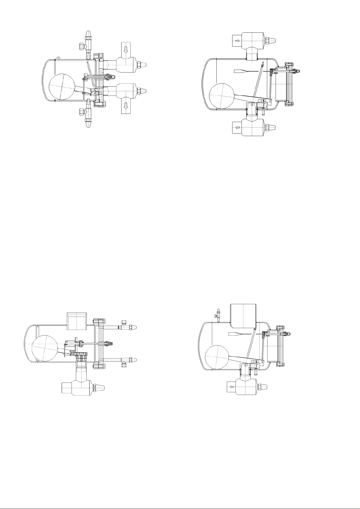
Fig.1a HR 1 – 3 Fig. 1b HR 4
3.2 LIEFERUMFANG
STANDARD LIEFERUMFANG HR
Absperrventile am Eintritt- und Austrittsstutzen bzw.
ASTM-Stutzen Schedule40 (bitte angeben)
Oben angebrachtes Regelventil zum Entlüften (EE3 bzw.
EE6 bei HR4)
Unten angebautes Entleerungsventil EA10 GB
Nocken G ½” / G ¼” kombiniert für Anschluss eines Sicherheitsventils (ab HR2)
Integrierte Unterdruckdüse
Blindkappe am Hebelaustritt
Rahmen, nur für den HR4
OPTIONALER LIEFERUMFANG HR
Befestigungskonsolen (lose beigepackt)
abweichende Ventilstellung (siehe Kap. 4.5)
Unterdruckdüse verschlossen
Entlüftungseinrichtung (aufsetzbares Wassergefäß mit
Schlauchverbindung zum Entlüftungsventil)
Einzelabnahme durch TÜV / andere Prüfgesellschaften
Sonderausführungen auf Anfrage
3.2 SCOPE OF DELIVERY
STANDARD SCOPE OF DELIVERY HR
Stop valves at inlet and outlet respective ASTM connections schedule 40 (please specify)
Top mounted regulating valve for purging (EE3 resp.
EE6 for HR4)
Bottom mounted drainage valve EA10GB
Combined G ½” / G ¼” threaded connection for safety
valve (larger than HR2)
Integrated low pressure nozzle
Cap for hand lever control
mounting frame, only for HR4
OPTIONAL SCOPE OF DELIVERY HR
Support brackets or mounting frame (supplied loose)
Alternative valve connection positions (see chapter 4.5)
Closed low pressure nozzle
Gas purge kit (special water container with hose and
connection to the purge valve)
Individual inspections of TÜV or other institutions
Special non standard executions upon request
Fig 1c HS30 – HS40
STANDARD LIEFERUMFANG HS
DIN- oder ASTM (Schedule 40) Eintrittsstutzen (bitte angeben)
Absperrventil oder ASTM-Stutzen am Austritt (bitte unbedingt angeben)
Verlängertes Einstellventil EE6 zum Entlüften, oben am
Deckel montiert
Verlängertes Absperrventil EA10GB zum Entleeren, unten
am Deckel montiert
Blindkappe am Hebelaustritt
Rahmen, nur für HS50
6
Fig. 1d HS50
STANDARD SCOPE OF DELIVERY HS
DIN-or ASTM (Schedule 40) inlet connection (please
specify)
Stop valve or ASTM connection at the outlet (please
specify)
Extended purge valve EE6, top mounted in the cover
plate
Extended stop valve EA10 GB for drainage, bottom
mounted in the cover plate
Cap for hand lever control
Mounting frame, only for HS50
Page 7
OPTIONALER LIEFERUMFANG HS
Unterdruckdüse
Entlüftungseinrichtung (aufsetzbares Wassergefäß mit
Schlauchverbindung zum Entlüftungsventil)
Einzelabnahme durch TÜV bzw. durch andere Prüfgesellschaften
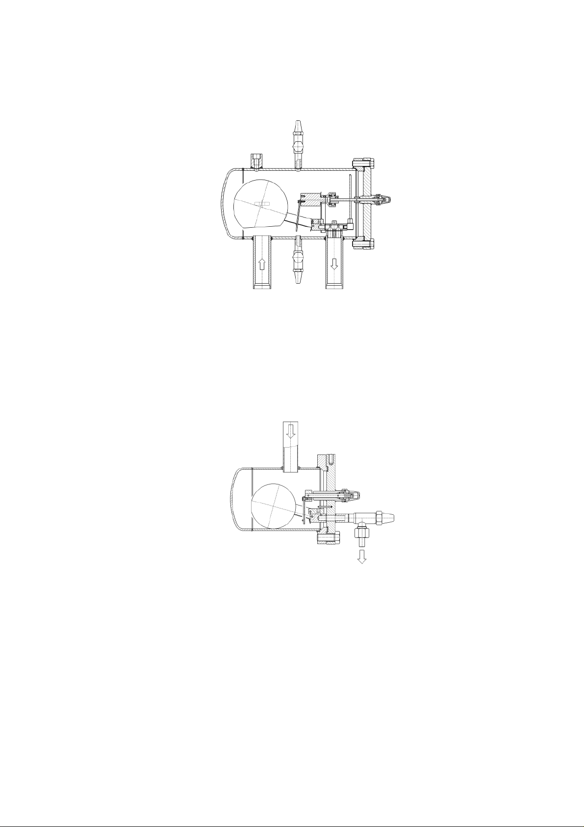
Fig. 1e WP2HR / WP3HR
OPTIONAL SCOPE OF DELIVERY HS
Low pressure nozzle for HS types
Gas purge kit (special water container with hose and
connection to the purge valve)
Individual inspections of TÜV or other institutions
STANDARD LIEFERUMFANG WPHR
DIN Eintritts- und Austrittsstutzen
Oben angebrachtes Regelventil EE3 zum Entlüften
Unten angebautes Entleerungsventil EA10 GB
Nocken G ½” / G ¼” kombiniert für Anschluss eines Sicherheitsventils
Integrierte Unterdruckdüse
Blindkappe am Hebelaustritt
STANDARD LIEFERUMFANG HR1BW
DIN Eintrittsstuten
Absperrventil EA10 am Austritt
Blindkappe am Hebelaustritt
STANDARD SCOPE OF DELIVERY WPHR
DIN inlet and outlet connection
Top mounted regulating valve EE3 for purging
Bottom mounted drainage valve EA10GB
Combined G ½” / G ¼” threaded connection for safety
valve
Integrated low pressure nozzle
Cap for hand lever control
Fig. 1f HR1BW
STANDARD SCOPE OF DELIVERY HR1BW
DIN inlet connection
Stop valve EA10 at the outlet
Cap for hand lever control
3.3 ABNAHMEN/BESCHEINIGUNGEN
Hochdruckschwimmer Regler werden als druckhaltende
Ausrüstungsteile ausgelegt, gefertigt und mit einer CEKennzeichnung gemäß Druckgeräterichtlinie ausgeliefert.
Als Grundlage dient das AD-Regelwerk, sowie aktuelle
Werkstoffnormen.
Außerdem können die Regler mit einer GOST Kennzeichnung bestellt werden.
Eine Bescheinigung, dass die ATEX-Richtlinie nicht auf
Hochdruckschwimmer-Regler anwendbar ist, wurde auf
Grundlage der Zündgefahrenbewertung erstellt und ist auf
Anfrage erhältlich.
7
3.3 INSPECTIONS/CERTIFICATES
High side float regulators are designed and manufactured as pressure resistant equipment and will be supplied with CE mark according to PED.
The evaluation is based on the AD regulation and actual
material standards.
The regulators can also be ordered with GOST mark.
A certificate, stating that the ATEX regulation does not
apply to high side float regulators, is available upon
request. It was based a risk assessment considering
potential ignition sources .
Page 8

Falls gewünscht geänderte Ventilstellung gemäß Kapitel
3.4 BESTELLANGABEN
Zur richtigen Auswahl Ihres HochdruckschwimmerReglers benötigen wir folgende Angaben:
• Kältemittel
• Kondensationstemperatur ....[ °C oder °F]
• Verdampfungstemperatur .....[°C oder °F]
• Kälte-/Wärmepumpenleistung ... [kW]
Haben Sie bereits einen Hochdruckschwimmer-Regler
ausgewählt, geben Sie bitte folgende Daten an:
• Baugröße: HR 1 bis HR 4, bzw. HS30 bis HS50
• Kältemittel: N- oder R- Kugel bzw bei HS auch SK Kugel
• Ausführung: -L, -M, -H
• Mit / ohne Unterdruckdüse bei HS-Reglern
• WP HR Schwimmer in 40 oder 65 bar
• Erforderliche Abnahmen/Dokumentation
•
4.6
• Sonderausführungen
Bestelltext
z.B. HR3-H mit N-Kugel oder
bei HS Reglern steht die erste Zahl für die Baugröße und
die zweite Zahl bedeutet:
1 N-Kugel ohne Unterdruckdüse
2 spezielle SK-Kugel ohne Unterdruckdüse
3 R-Kugel ohne Unterdruckdüse
4 N-Kugel mit Unterdruckdüse
5 spezielle SK-Kugel mit Unterdruckdüse
6 R-Kugel mit Unterdruckdüse
z.B. HS34-M (HS-Regler mit N-Kugel, mit Unterdruckdüse
und in M-Ausführung)
3.4 ORDERINFORMATION
In order to select the correct high side float regulator for
your application we will need the following information
• Refrigerant
• Condensing temperature …. [°C or °F]
• Evaporating temperature....[°C or °F]
• Capacity … [KW]
Please always specify the following technical information
when ordering a float regulator:
• Size: HR 1 to HR 4, resp. HS30 to HS50
• Refrigerant: N- or R-ball, resp. for HS also SK-ball
• Execution: –L, -M, -H
• With or without low pressure nozzle for HS-regulators
• WP HR regulators in 40 or 65 bar
• Required standard of inspection and certification
documentation.
• If required alternative valve position, see chapter 4.6
• Any special non standard requirements
Order text
e.g. HR3 with N-float ball or
for HS-regulators the first number indicates the size,
wheras the second number has the following meaning:
1 N-float ball, without low pressure nozzle
2 special SK- ball, without low pressure nozzle
3 R- float ball, without low pressure nozzle
4 N-Kugel float ball, with low pressure nozzle
5 special SK- ball, with low pressure nozzle
6 R- float ball, with low pressure nozzle
e.g. HS34-M (HS-regulator with N-float ball, with low
pressure nozzle and M-execution)
Ersatzteilbestellungen
Die Schiebersteuerung betreffende Ersatzteile können nur
als gesamte Steuereinheit geliefert werden, da eine Justierung der Teile erforderlich ist.
Bitte geben Sie Typ, Kältemittel und Baujahr an, wenn
Sie eine Steuereinheit bestellen:
z.B. HR3 – M, NH3, 05/96
Ordering replacement parts
Replacements parts for the slide valve control are only
available as a complete control unit, including the ball
float, because all parts need to be adjusted.
Please indicate type, refrigerant and year when ordering a control unit:
e.g. HR3 – M, NH3, 05/96
8
Page 9
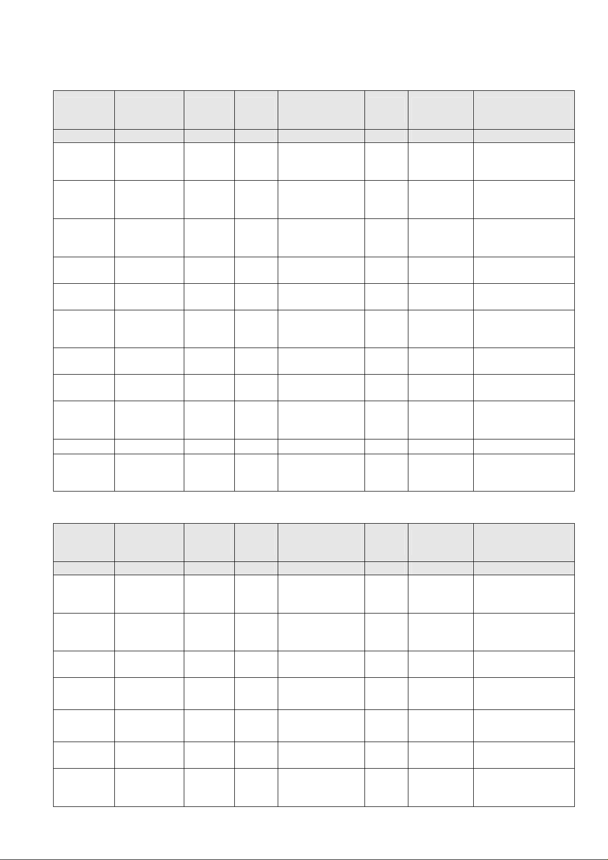
3.5 STEUEREINHEIT
3.5 CONTROL UNIT
Artikel-Nr.
Article No.
3591.000232
3591.000233
3591.000234
3591.000235
3591.000236
3591.000237
3591.000238
3591.000239
3591.000240
3591.000245
3591.000246
3591.000242
3591.000243
3591.000247
3591.000248
3591.000249
3591.000254
3591.000255
3591.000251
3591.000252
3591.000256
3591.000257
3591.000258
Typ
Model
HR1-L
HR1-M
HR1-H
HR1-L
HR1-M
HR1-H
HR2-L
HR2-M
HR2-H
HR2 SK-M
HR2 SK-H
HR2-M
HR2-H
HR3-L
HR3-M
HR3-H
HR3 SK-M
HR3 SK-H
HR3-M
HR3-H
HR4-L
HR4-M
HR4-H
Kugel-Art
Ball-type
1)
N
N
N
R
R
R
N
N
N
SK
SK
R
R
N
N
N
SK
SK
R
R
N
N
N
Drossel
Orifice
[mm²] [mm] [mm] ~ [mm] ~ [kg]
5
3
2
11
6
4
56
37
19
30
19
56
37
159
108
69
85
69
159
108
333
236
154
Unterdruckdüse ø
Low-press. nozzle
ø
0,7
0,7
0,7
0,7
0,7
0,7
1,5
1,5
1,0
2,0
1,5
1,5
1,0
3,0
3,0
2,0
3,0
2,0
3,0
2,0
6,0
6,0
4,0
Kugel ø
Ball ø
100
100
100
100
100
100
120
120
120
150
150
120
120
150
150
150
200
200
150
150
200
200
200
Länge Hebel
Length Lever
87
87
87
48
87
87
95
87
87
87
87
95
87
148
133
133
133
133
148
133
300
300
300
Gewicht Steuereinheit
Weight Control Unit
0,31
0,31
0,31
0,49
0,51
0,51
0,44
0,44
0,44
0,70
0,70
0,65
0,65
0,90
0,90
0,90
1,75
1,75
1,2
1,2
2,65
2,65
2,65
3591.000262 HR4 SK-H - 146 4,0 230 300 2,5
3591.000259
3591.000260
3591.000261
HR4-L
HR4-M
HR4-H
R
R
R
470
333
236
6,0
6,0
4,0
150
150
150
300
300
300
3,36
3,36
3,36
Steuereinheiten komplett bis 05/2009 Control unit complete until 05/2009
Artikel-Nr.
Article No.
3591.713001
3591.713002
3591.713003
3591.713004
3591.713005
3591.713006
3591.713007
3591.713008
3591.713009
3591.713010
3591.713011
3591.713012
3591.713013
3591.713014
3591.713015
3591.713016
3591.813001
3591.813002
3591.813003
Typ
Model
HS31-L
HS31-M
HS31-H
HS32-L
HS32-M
HS32-H
HS33-M
HS33-H
HS34-L
HS34-M
HS34-H
HS35-L
HS35-M
HS35-H
HS36-M
HS36-H
HS41-L
HS41-M
HS41-H
Kugel-Art
Ball-type
1)
N
N
N
SK
SK
SK
R
R
N
N
N
SK
SK
SK
R
R
N
N
N
Drossel
Orifice
[mm²] [mm] [mm] ~ [mm] ~ [kg]
56
37
19
52
30
19
56
37
56
37
19
52
30
19
56
37
159
108
69
Unterdruckdüse ø
Low-press. nozzle
ø
ohne
without
ohne
without
ohne
without
mit
with
mit
with
mit
with
ohne
without
Kugel ø
Ball ø
120
120
120
150
150
150
120
120
120
120
120
150
150
150
120
120
150
150
150
Länge Hebel
Length Lever
95
87
87
87
87
87
95
87
95
87
87
87
87
87
95
87
148
133
133
Gewicht Steuereinheit
Weight Control Unit
0,44
0,44
0,44
0,70
0,70
0,70
0,65
0,65
0,44
0,44
0,44
0,70
0,70
0,70
0,65
0,65
0,90
0,90
0,90
9
Page 10

3591.813004
3591.813005
3591.813006
HS42-L
HS42-M
HS425-H
SK
SK
SK
140
85
69
ohne
without
200
200
200
133
133
133
1,75
1,75
1,75
3591.813007
3591.813008
3591.813009
3591.813010
3591.813011
3591.813012
3591.813013
3591.813014
3591.813015
3591.813016
HS43-M
HS43-H
HS44-L
HS44-M
HS44-H
HS45-L
HS45-M
HS45-H
HS46-M
HS46-H
R
R
N
N
N
SK
SK
SK
R
R
159
108
159
108
69
140
85
69
159
108
ohne
without
mit
with
mit
with
mit
with
150
150
150
150
150
200
200
200
150
150
148
133
148
133
133
133
133
133
148
133
1,2
1,2
0,90
0,90
0,90
1,75
1,75
1,75
1,2
1,2
Steuereinheiten komplett für HS ab 06/2009 Control unit complete for HS until 05/2009
Artikel-Nr.
Article No.
3591.713021
3591.713022
3591.713023
3591.713024
3591.713025
3591.713026
3591.713027
3591.713028
3591.713029
3591.713030
3591.713031
3591.713032
3591.713033
3591.713034
3591.713035
3591.713036
3591.813021
3591.813022
3591.813023
3591.813024
3591.813025
3591.813026
Typ
Model
HS31-L
HS31-M
HS31-H
HS32-L
HS32-M
HS32-H
HS33-M
HS33-H
HS34-L
HS34-M
HS34-H
HS35-L
HS35-M
HS35-H
HS36-M
HS36-H
HS41-L
HS41-M
HS41-H
HS42-L
HS42-M
HS425-H
Kugel-Art
Ball-type
1)
N
N
N
SK
SK
SK
R
R
N
N
N
SK
SK
SK
R
R
N
N
N
SK
SK
SK
Drossel
Orifice
[mm²] [mm] [mm] ~ [mm] ~ [kg]
56
37
19
52
30
19
56
37
56
37
19
52
30
19
56
37
159
108
69
140
85
69
Unterdruckdüse ø
Low-press. nozzle
ø
ohne
without
ohne
without
ohne
without
mit
with
mit
with
mit
with
ohne
without
ohne
without
Kugel ø
Ball ø
120
120
120
150
150
150
120
120
120
120
120
150
150
150
120
120
150
150
150
200
200
200
Länge Hebel
Length Lever
95
87
87
87
87
87
95
87
95
87
87
87
87
87
95
87
148
133
133
133
133
133
Gewicht Steuereinheit
Weight Control Unit
0,44
0,44
0,44
0,70
0,70
0,70
0,65
0,65
0,44
0,44
0,44
0,70
0,70
0,70
0,65
0,65
0,90
0,90
0,90
1,75
1,75
1,75
3591.813027
3591.813028
3591.813029
3591.813030
3591.813031
3591.813032
3591.813033
3591.813034
3591.813035
3591.813036
HS43-M
HS43-H
HS44-L
HS44-M
HS44-H
HS45-L
HS45-M
HS45-H
HS46-M
HS46-H
R
R
N
N
N
SK
SK
SK
R
R
159
108
159
108
69
140
85
69
159
108
ohne
without
mit
with
mit
with
mit
with
150
150
150
150
150
200
200
200
150
150
148
133
148
133
133
133
133
133
148
133
1,2
1,2
0,90
0,90
0,90
1,75
1,75
1,75
1,2
1,2
3591.000256
3591.000257
3591.000258
3591.000259
3591.000260
3591.000261
HS51/54-L
HS51/54-M
HS51/54-H
HS53/56-L
HS53/56-M
HS53/56-H
N
N
N
R
R
R
333
236
154
470
333
236
ohne / optional
without / optional
ohne / optional
without / optional
200
200
200
200
200
200
300
300
300
300
300
300
2,65
2,65
2,65
3,36
3,36
3,36
10
Page 11
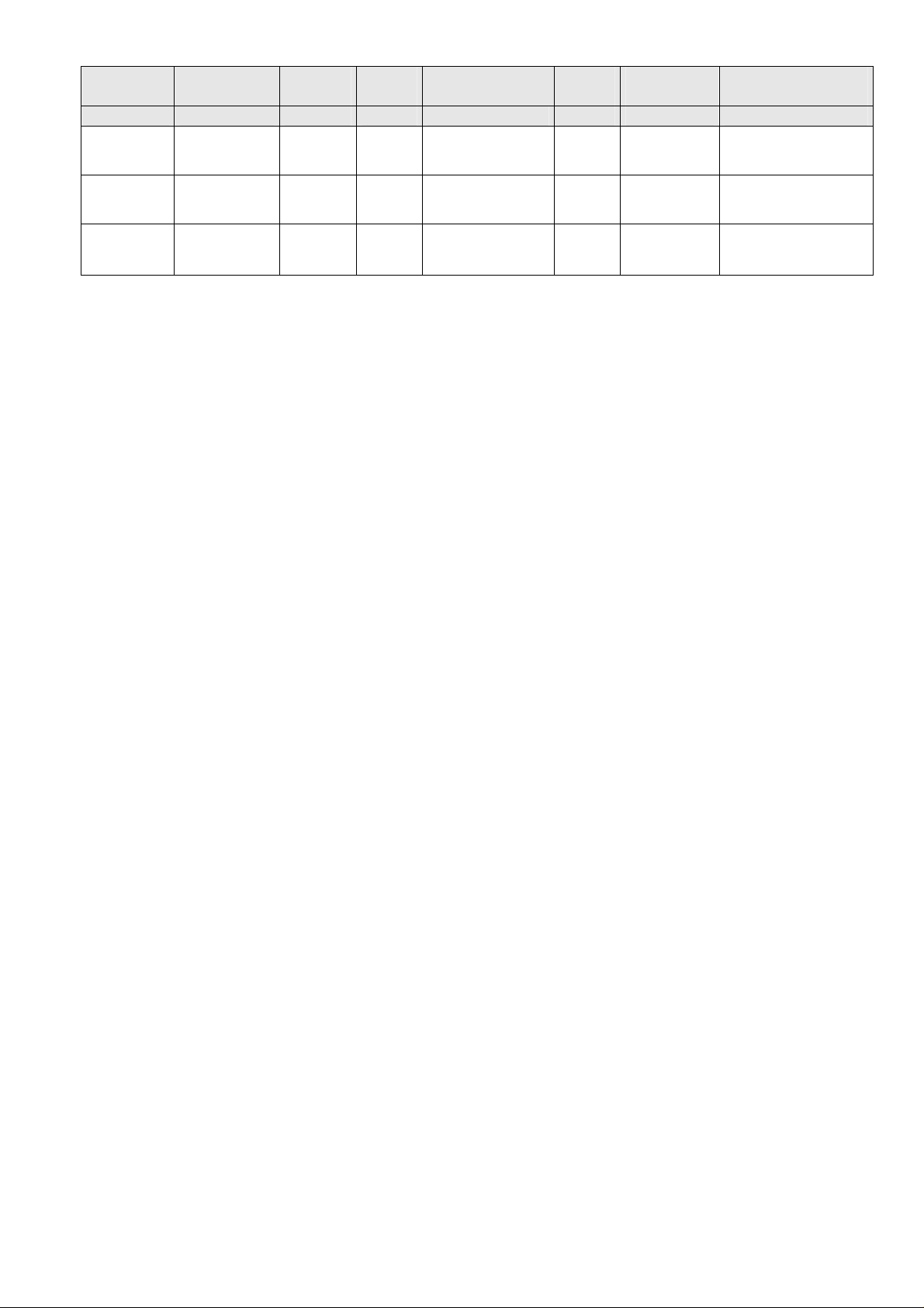
Artikel-Nr.
Article No.
3591.000244
3591.000253
3591.000270
3591.000232
3591.000233
3591.000234
3591.000235
3591.000236
3591.000237
1)
Kugel Art:
Typ
Model
WP2 HR
WP3 HR
WP3HR-65bar
HR1 BW-L
HR1 BW-M
HR1 BW-H
HR1 BW-L
HR1 BW-M
HR1 BW-H
Kugel-Art
Ball-type
1)
WP
WP
WP
N
N
N
R
R
R
Drossel
Orifice
Unterdruckdüse ø
Low-press. nozzle ø
Kugel ø
Ball ø
Länge Hebel
Length Lever
Gewicht Steuereinheit
Weight Control Unit
[mm²] [mm] [mm] ~ [mm] ~ [kg]
11
46
46
5
3
2
11
6
4
1,8
3,0
3,0
-
-
-
-
-
-
1)
float ball type:
150
200
200
100
100
100
100
100
100
87
133
133
87
87
87
48
87
87
0,38
1,01
1,03
0,31
0,31
0,31
0,49
0,51
0,51
N für Kältemittel mit geringer Dichte ρ < 1000 kg/m³ N for refrigerants with low density ρ < 1000 kg/m³
z.B. NH3 (R717), Propan (R290), Öl e.g. NH3 (R717), Propan (R290), oil
R für Kältemittel mit einer Dichte ρ > 1000 kg/m³ R for refrigerants with density ρ > 1000 kg/m³
z.B. R22, R507, R134a, R404a e.g. R22, R507, R134a, R404a
SK für Kältemittel mit erhöhter Kondensationstemperatur SK for refrigerants with higher condensing temperature
WP für Einsatz in Wärmepumpen WP for heat pump applications
4. TECHNISCHE DATEN
4.
TECHNICAL
DATA
4.1 MATERIALIEN
Gehäusemantel: P 265 GH (St 35.8)
Flansch: P 265 GH
Klöpperböden: P 265 GH
Schrauben: A2-70
Dichtung: Centellen
Schutzkappe: Al
Stopfbuchse: Al
Stopfbuchspackung: Ne
Hebel/Knebel: St
Anstrich: W9.1 + W9.2
W9.1 + W9.2 = 2k Epoxydharz nach DIN ISO 12944/5, RAL
7001
4.2 DRUCK/TEMPERATUR BEREICHE
HR, HS50 und HR1BW Hochdruckschwimmer-Regler
Max. zul. Druck PS: 25 bar zwischen +75 / -10°C,
18,75 bar zwischen -10 /-60°C
Prüfdruck Pt: 37 bar Öldruck
HS30 und HS40 Hochdruckschwimmer-Regler
Max. zul. Druck PS: 40 bar zwischen +75 / -10°C,
30 bar zwischen –10 / -60°C
Prüfdruck Pt: 59 bar Öldruck
WP Hochdruckschwimmer-Regler
40 bar Ausführung
Max. zul. Druck PS: 40 bar zwischen +90 / -10°C,
30 bar zwischen –10 / -60°C
Prüfdruck Pt: 59 bar Öldruck
WP Hochdruckschwimmer-Regler
65 bar Ausführung
Max. zul. Druck P
: 65 bar zwischen +100 / -10°C,
S
49 bar zwischen –10 / -60°C
Prüfdruck Pt: 100 bar Öldruck
4.1 MATERIALS
Housing: P 265 GH (St 35.8)
Flange: P 265 GH
End caps: P 265 GH
Bolts: A2-70
Gaskets: Centellen
Cap: Al
Gland: Al
Packing: Ne
Lever: St
Painting system: W9.1 + W9.2
W9.1 + W9.2 = 2 k epoxy finish according to DIN ISO
12944/5, RAL 7001
4.2 PRESSURE/TEMPERATURE RANGE
HR, HS50 and HR1BW type high side float regulators
Max. allow. Pressure PS: 25 bar between +75 / -10 °C,
18.75 bar between –10 /-60 °C
Test Pressure: 37 bar oil pressure
HS30 and HS40 type high side float regulators
Max. allow. Pressure PS: 40 bar between +75 / -10 °C,
30 bar between –10 / -60°C
Test pressure Pt: 59 bar oil pressure
WP type high side float regulators
40 bar execution
Max. allow. Pressure PS: 40 bar between +90 / -10 °C,
30 bar between –10 / -60°C
Test pressure Pt: 59 bar oil pressure
WP type high side float regulators
65 bar execution
Max. allow. Pressure P
: 65 bar between +100 / -10 °C,
S
49 bar between –10 / -60°C
Test pressure Pt: 100 bar oil pressure
11
Page 12
Steuereinheit,
41; 42; 43; 44; 2x45; 6x46, 2x 47
Befestigungskonsole
Entlüftungsvorric
Nur für NH
Dichtungssatz
1x31, 1x32, 6x33 2x34,1x35, 2x36
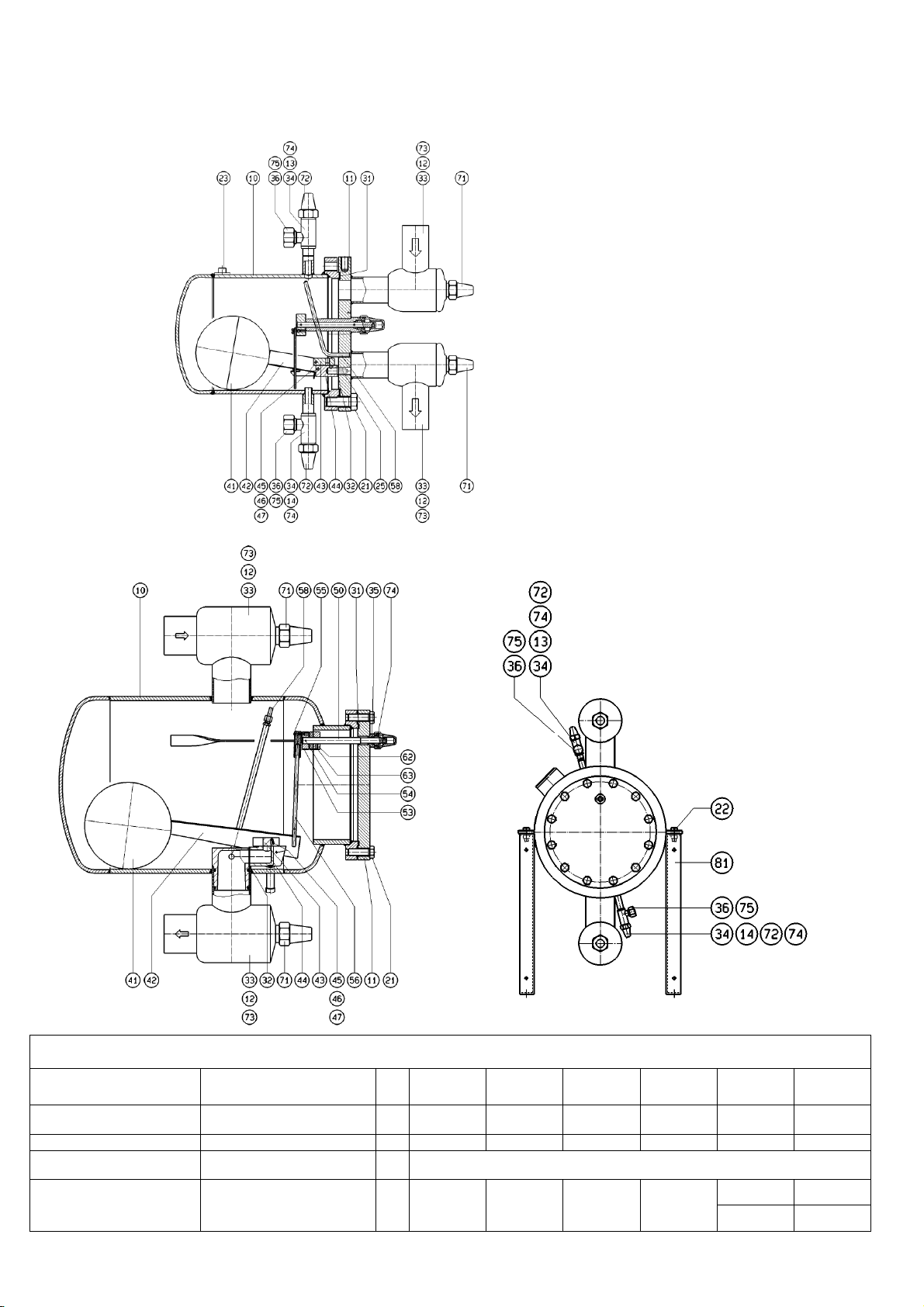
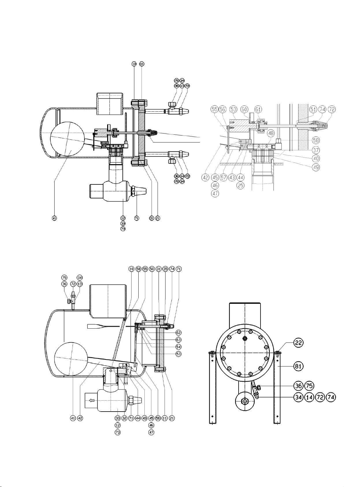
4.3 ÜBERBLICK 4.3 OVERVIEW
Hochdruckschwimmer-Regler Modelle
HR
Float Regulator Models
Fig. 2a HR1 – HR3
Fig. 2b HR4
Komplette HR-Austausch Baugruppen
Complete HR replacement assemblies
mit Teilen:
htung
mit Teilen 91; 92; 93
3
,
mit Teilen:
Control unit,
41; 42; 43; 44; 2x45; 6x46, 2x 47
Brackets
Vent Device,
ammonia with parts 91; 92; 93
Set of gaskets
1x31, 1x32, 6x33, 2x34, 1x35, 2x36
12
with parts:
O
nly for
with parts:
Part
HR1 / HR1
No.
40
BW
Kap.3.4
chap. 3.4
HR2 /
WP2 HR
Kap.3.4
chap. 3.4
HR3 /
WP3 HR
Kap.3.4
chap. 3.4
HR4 /
HS50
Kap.3.4
chap. 3.4
HS30 HS40
Kap.3.4
chap. 3.4
70 3911.000010 3911.000010 3911.000010 ----- --- --90
E30 3591.000363 3591.000364 3591.000365 3591.000366
3591.000346
bis/until 05/2009
3591.000395
ab/from 06/2009
3591.000401
Kap.3.4
chap. 3.4
bis/until 05/2009
3591.000396
ab/from 06/2009
3591.000402
Page 13
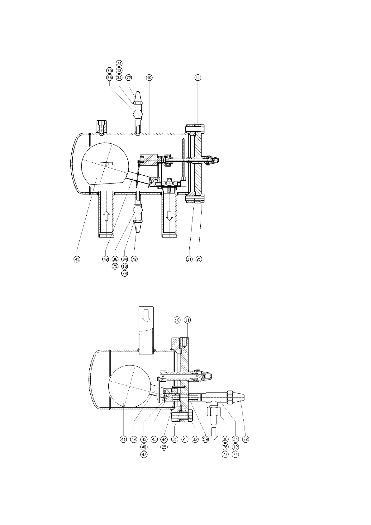
4.4 Overview
4.4 Überblick
Schnittzeichnungen HS
Sectional drawings
Fig. 2c HS30 – HS40
Fig. 2c HS30 – HS40
13
Fig. 2d HS50
Page 14
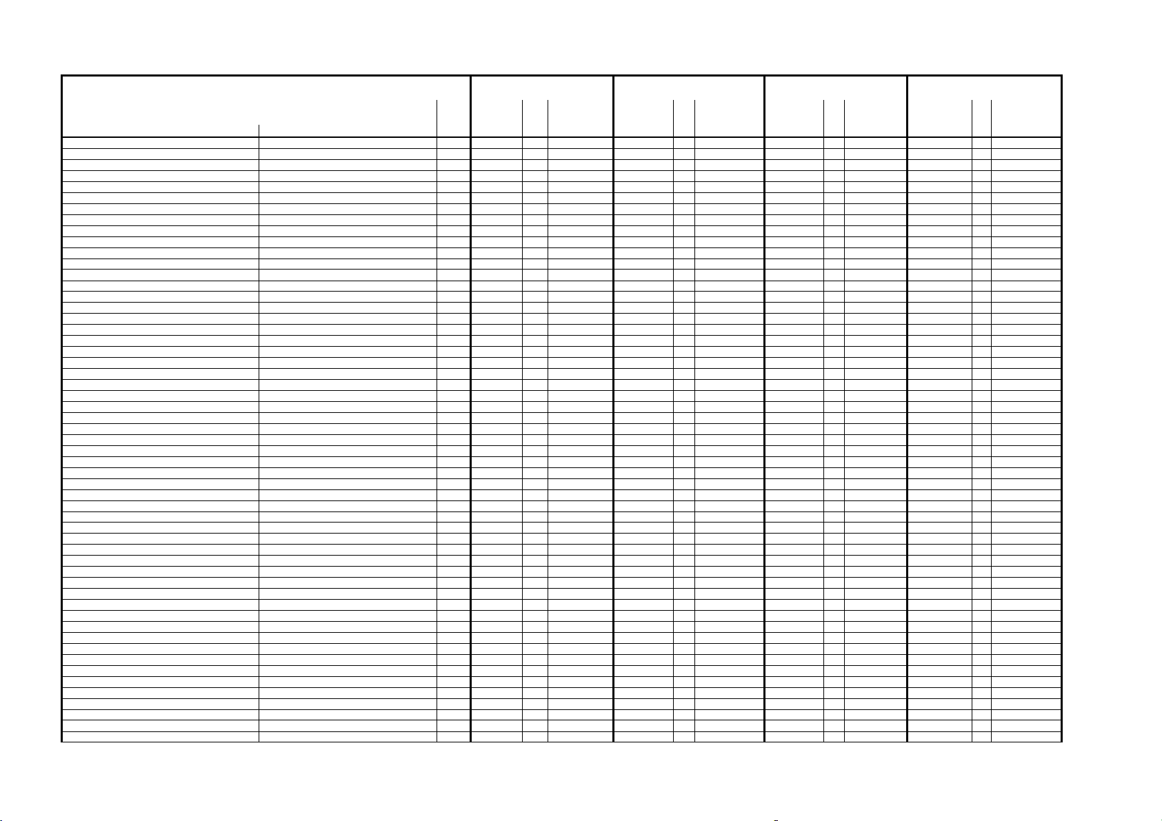
Overview
4.4 Überblick
Schnittzeichnungen WPHR / HR1BW
4.4
Sectional drawings
Fig. 2e WP2HR / WP3HR
14
Fig. 2f HR1BW
Page 15

A
n
zahl
A
n
zahl
Teileliste
Spezielle Ersatzteilwünsche nur nach Rücksprache mit dem Lieferanten!
Special parts only upon request!
No.
Gehäuse
Deckel
Eingangsventil/Ausgangsventil
Entlüftungsventil
Ablaßventil
6kt - Schraube
6kt – Schraube für 65bar Ausführung
6kt - Schraube
6kt - Mutter
Anschweißmutter
Zylinderschraube mit Innen-6kt. (WP 2-3 HR)
Zylinderschraube mit Innen-6kt.
Flachdichtung
Dichtung - Düseneinsatz
Stopfbuchspackung zu 12
Stopfbuchspackung zu 13
Stopfbuchspackung zu 50
Flachdichtung zu 13 + 14 + 12 HR 1 BW
Dichtung Düsenhalter
Kugel
Kugelarm
Steuerschieber
Düseneinsatz
Bolzen
Scheibe
Splint
Düsenhalter ( WP 2-3 HR )
Aufnahme-Platte ( WP 2-3 HR )
Drehachse
Drehachse für WP 65bar
Spannstift zu 50
Grundring
Exzenter
Spannstift zu 53
Flachkopfschraube / Bolzen ( HR 4 )
Zugstange / Druckstab
Zugstange / Druckstab - WP HR
Führungsbügel
Unterdruckförderer
Spannstift zu HR 1 BW
Hebelstütze WP - HR
Kupplungsstück WP - HR
Stellring WP - HR
Spannstift/Gewindestift WP - HR + HR 4
Schutzkappe zu 12
Schutzkappe zu 13 + 14 + 12 HR 1BW + 50
Stopfbuchse zu 12
Stopfbuchse zu 50
Blindkappe
Überwurfmutter zu 12 HR 1 BW
Schweißnippel zu 12 HR 1 BW
Rahmenfuß
Entlüftungsbehälter
Schlauch komplett
Schaftschraube
Teil Abmessung
main housing
cover plate
inlet valve
vent valve
drain valve
cover plate hexagon screw
cover plate hexagon screw for 65 bar
hexagon head cap screw
haxagon nut
nut insert
hexagon socket screw
hexagon socket screw
cover plate gasket
gasket behind orifice house
packing for 12
packing for 13
packing for 50
gasket for valve cap for 13+14+12 HR1BW
gasket at orifice
ball
ball lever
slide valve
orifice block
pin
washer
solit pin
mount at orifice
mounting plate
spindle
Spindle for WP 65bar
locking pin for 50
base ring
excenter for hand operation
locking pin for 53
pan head screw/bolt
tow/pressure bar
tow/pressure bar
guide bracket
low pressure nozzle
locking pin for HR 1 BW
column for WP-HR
clutch .... for WP - HR
collet WP -HR
locking pin/grub screw for WP - HR+HR 4
spindle cap for 12
spindle cap for 13+14+12 HR 1BW + 50
gland for 12
gland for 50
blind cap
cap nut for 12 HR 1 BW
welded-in stub
frame, galvanized
vent container
hose
threaded pin
Part Dimension
10 Typ 1 1 ----------------- Typ 2 1 ----------------- Typ 3 1 ----------------- Typ 4 1 ----------------11 Typ 1 1 ----------------- Typ 2 1 ----------------- Typ 3 1 ----------------- Typ 4 1 ----------------12 EA 20 1 ----------------- EA 32 1 ----------------- EA 50 1 ----------------- EA 80 1 ----------------13 EE 3 GB 1 ----------------- EE 3 GB 1 ----------------- EE 3 GB 1 ----------------- EE 6 GB 1 ----------------14 EA 10 GB 1 ----------------- EA 10 GB 1 ----------------- EA 10 GB 1 ----------------- EA 10 GB 1 ----------------21 M16x40 6 5111.CLA3B3 M16x40 8 5111.CLA3B3 M16x50 12 5111.CLA3BD M16 x 50 12 5111.CLA3BD
21 M20x70 16 5111.CLC2BX
22a ------------ -- ----------------- ------------ -- ----------------- ------------ -- ----------------- M12 x 35 4 5111.CH81AY
22b ------------ -- ----------------- ------------ -- ----------------- ------------ -- ----------------- M12 4 5151.AH8100
23 M 10 1 ----------------- M 10 1 ----------------- M 10 1 ----------------- --------------- -- -----------------
24 ------------ -- ----------------- M8x30 2 ----------------- M8x30 2 ----------------- ------------ -- -----------------
25 M8x20 2 5112.BC61AJ M8x20 2 5112.BC61AJ M8x20 2 5112.BC61AJ M6x20 2 5112.BC51AJ
31 125/145x2 1 5632.1DGE0K 180/200x2 1 5632.1EZFJK 260/280x2 1 5632.1H7HRK 260/280x2 1 5632.1H7HRK
32 18/50x2 1 5632.1AHBDK 18/50x2 1 5632.1AHBDK 26x60x2 1 5632.1APBNK 43/74x2 1 5632.1B6C1K
33 8/14x8 1 5643.ABAP01 8/14x8 1 5643.ABAP01 12x4 3 5642.ABAX02 19x4 3 5642.ABBL01
34 8/14x8 1 5643.ABAP01 8/14x8 1 5643.ABAP01 8/14x8 1 5643.ABAP01 8/14x8 1 5643.ABAP01
35 8/14x8 1 5643.ABAP01 8/14x8 1 5643.ABAP01 8/14x8 1 5643.ABAP01 12x4 3 5642.ABAX02
36 10/18x2 1 5632.1A9AHK 10/18x2 1 5632.1A9AHK 10/18x2 1 5632.1A9AHK 10/18x2 1 5632.1A9AHK
37 ------------ -- ----------------- ø 45x2 1 ----------------- ø 60x2 1 ----------------- ------------ -- -----------------
41 ø 100 1 ----------------- ø 120 1 ----------------- ø 150 1 ----------------- ø 200 1 -----------------
42 Typ 1 1 ----------------- Typ 2 1 ----------------- Typ 3 1 ----------------- Typ 4 1 -----------------
43 34x15x12,5 1 ----------------- 34x15x12,5 1 ----------------- 40x25x12.5 1 ----------------- 60x40x20,5 1 -----------------
44 50x35x18 1 ----------------- 50x35x18 1 ----------------- 60x44x26 1 ----------------- 85x44x65 1 -----------------
45 ø 4x25 2 ----------------- ø 4x25 2 ----------------- ø 4x35 2 ----------------- ø 4x35x22 2 -----------------
46 A 4,3 6 ----------------- A 4,3 6 ----------------- A 4,3 6 ----------------- A 4,3 6 -----------------
47 ø 1x15 2 ----------------- ø 1x15 2 ----------------- ø 1x15 2 ----------------- ø 1x15 2 -----------------
48 ------------ -- ----------------- Typ 1 1 ----------------- Typ 2 1 ----------------- ------------ -- -----------------
49 ------------ -- ----------------- ø 45x19 1 ----------------- ø 60x19 1 ----------------- ------------ -- -----------------
50 ø 8x115 1 3591.000123 ø 8x135 1 3591.000124 ø 8x135 1 3591.000124 ø 14x200 1 3591.000125
50 ø 8x200 1 3591.000120
51 ø 3x10 1 5723.AA0301 ø 3x10 1 5723.AA0301 ø 3x10 1 5723.AA0301 --------------- -- -----------------
52 ø 13x8x2 1 6438.000004 ø 13x8x2 1 6438.000004 ø 13x8x2 1 6438.000004 --------------- -- -----------------
53 ø 25x15 1 3591.000115 ø 35x15 1 3591.000116 ø 35x15 1 3591.000116 ø 40x16 1 3591.000117
54 ø 3x30 1 5723.AA0302 ø 3x30 1 5723.AA0302 ø 3x30 1 5723.AA0302 ø 3x30 1 5723.AA0302
55 M4 x 5 1 5117.AB30A4 M4 x 5 1 5117.AB30A4 M4 x 5 1 5117.AB30A4 ø 4x25x22 1 5724.A00401
56 ø 3x60 1 3591.000095 ø 3x94 1 3591.000096 ø 3x121 1 3591.000097 ø 8x1x235 1 3591.000100
56 ------------ -- ----------------- ø 3x94 1 3591.000096 ø 3x118 1 3591.000093 --------------- -- -----------------
57 ------------ -- ----------------- 67,5x50x15 1 ----------------- 65,5x60x15 1 ----------------- --------------- -- -----------------
58 ø 6x1x107 1 ----------------- ø 6x1x156 1 ----------------- ø 6x1x230 1 ----------------- ø 6x1x360 1 -----------------
59 ø 3x30 1 ----------------- ----------------- -- ----------------- ----------------- -- ----------------- --------------- -- -----------------
60 ------------ -- ----------------- Typ 1 1 3591.000111 Typ 2 1 3591.000112 ------------ -- -----------------
61 ------------ -- ----------------- ø 50x30 1 3591.000118 ø 50x30 1 3591.000118 ------------ -- -----------------
62 ------------ -- ----------------- ø 8/16x15 1 3591.000126 ø 8/16x15 1 3591.000126 ø 14/40x16 1 3591.000127
63 ------------ -- ----------------- ø 3x30 1 5723.AA0302 ø 3x30 1 5723.AA0302 M6x12 1 5121.CD50AB
71 SW 27 2 6436.AAP270 SW 27 2 6436.AAP270 SW 27 2 6436.AAP270 SW 46 2 6436.AAP460
72 SW 27 2 6436.AAP270 SW 27 2 6436.AAP270 SW 27 2 6436.AAP270 SW 27 2 6436.AAP270
73 SW 12 1 6438.000006 SW 12 1 6438.000006 SW 17 1 6438.000002 SW 22 1 6438.000003
74 SW 12 1 6438.000001 SW 12 1 6438.000001 SW 12 1 6438.000001 SW 17 1 6438.000002
75 G 1/2 2 6436.ABDD00 G 1/2 2 6436.ABDD00 G 1/2 2 6436.ABDD00 G 1/2 2 6436.ABDD00
76 SW 27 1 6436.ACDD00 ------------ -- ----------------- ------------ -- ----------------- ------------ -- -----------------
77 6/13 1 6424.AH0001 ------------ -- ----------------- ------------ -- ----------------- ------------ -- -----------------
81 ------------ -- ----------------- ----------------- -- ----------------- ----------------- -- ----------------- 600x495 2 -----------------
91 ------------ 1 ----------------- ------------ 1 ----------------- ------------ 1 ----------------- ------------ 1 -----------------
92 ------------ 1 ----------------- ------------ 1 ----------------- ------------ 1 ----------------- ------------ 1 -----------------
93 M 10x65 1 ----------------- M 10x65 1 ----------------- M 10x65 1 ----------------- M 10x65 1 -----------------
HR 1 / HR 1 BW HR 2 HR 3 HR 4
WP 2 HR WP 3 HR
Artikelnr. Abmessung Artikelnr. Abmessung Artikelnr. Abmessung
Part - No. Dimension Part - No. Dimension Part - No. Dimension
Anzahl
quantity
quantity
quantity
Parts-List
Artikelnr.
Part - No.
Anzahl
quantity
15
Page 16
Teileliste
A
n
zahl
A
n
zahl
A
n
zahl
Spezielle Ersatzteilwünsche nur nach Rücksprache mit dem Lieferanten!
Special parts only upon request!
No.
Gehäuse
Deckel
Eingangsventil
Entlüftungsventil
Ablaßventil
6kt - Schraube
6kt - Schraube
6kt - Mutter
Zylinderschraube mit Innen-6kt.
Zylinderschraube mit Innen-6kt. (Sonderkugel)
Zylinderschraube mit Innen-6kt.
Flachdichtung
Dichtung - Düseneinsatz
Stopfbuchspackung zu 12
Stopfbuchspackung zu 13 + 14
Stopfbuchspackung zu 50
Flachdichtung zu 13 + 14
Dichtung Düsenhalter
Kugel
Kugelarm
Steuerschieber
Düseneinsatz
Bolzen
Scheibe
Splint
Düsenhalter
Aufnahme-Platte
Drehachse
Spannstift zu 50
Exzenter
Spannstift zu 53
Flachkopfschraube / Bolzen ( HR 4 )
Zugstange / Druckstab
Zugstange / Druckstab - HR SK
Führungsbügel
Unterdruckförderer
Hebelstütze
Kupplungsstück
Kupplungsstück
Spannstift/Gewindestift HS 50
Schutzkappe zu 12
Schutzkappe zu 13 + 14 + 50
Stopfbuchse zu 12
Stopfbuchse zu 50
Blindkappe
Rahmenfuß
Entlüftungsbehälter
Schlauch komplett
Schaftschraube
Teil Abmessung Artikelnr. Abmessung Artikelnr. Abmessung Artikelnr.
part
main housing
cover plate
outlet valve
vent valve
drain valve
cover plate hexagon screw
hexagon head cap screw
haxagon nut
hexagon socket screw
hexagon socket screw
hexagon socket screw
cover plate gasket
gasket behind orifice house
packing for 12
packing for 13 + 14
packing for 50
gasket for valve cap for 13+14
gasket at orifice
ball
ball lever
slide valve
orifice block
pin
washer
solit pin
mount at orifice
mounting plate
stem for hand operation
locking pin for 50
excenter for hand operation
locking pin for 53
pan head screw/bolt
tow/pressure bar
tow/pressure bar
guide bracket
low pressure nozzle
column
clutch ....
clutch ....
locking pin/grub screw for HS 50
spindle cap for 12
spindle cap for 13+14 + 50
gland for 12
gland for 50
blind cap
frame, galvanized
vent container
hose
threaded pin
10 Typ 3 1 ----.------ Typ 4 1 ----.------ Typ 5 1 ----.------
11 Typ 3 1 ----.------ Typ 4 1 ----.------ Typ 5 1 ----.------
12 EA 50 1 ----.------ EA 80 1 ----.------ EA 80 1 ----.------
13 EE 6 GB/L 1 ----.------ EE 6 GB/L 1 ----.------ EE 6 GB 1 ----.------
14 EA 10 GB/L 1 ----.------ EA 10 GB/L 1 ----.------ EA 10 GB 1 ----.------
21 M16x60 12 5111.CLA3BN M16x70 12 5111.CLA3BX M16x50 12 5111.CLA3BD
22a ---------- -- ----.------ ---------- -- ----.------ M12x35 4 5111.CH81AY
22b ---------- -- ----.------ ---------- -- ----.------ M12 4 5151.AH8100
24a M8x30 2 5112.BC61AT M8x45 2 5112.BC61B8 ---------- -- ----.-----24b M8x45 2 5112.BC61B8 M8x65 2 5112.BC61BS ---------- -- ----.------
25 M8x20 2 5112.BC61AJ M8x20 2 5112.BC61AJ M6x20 2 5112.BC51AJ
31 206/225x2 1 5632.1FPG8K 311/330x2 1 5632.1IMJ5K 260/280x2 2 5632.1H7HRK
32 18/50x2 1 5632.1AHBDK 26/50x2 1 5632.1APBNK 43/74x2 1 5632.1B6C1K
33 12x4 3 5642.ABAX02 19x4 3 5642.ABBL01 19x4 3 5642.ABBL01
34 8/14x8 1 5643.ABAP01 8/14x8 1 5643.ABAP01 8/14x8 1 5643.ABAP01
35 8/14x8 1 5643.ABAP01 8/14x8 1 5643.ABAP01 12x4 3 5642.ABAX02
36 10/18x2 1 5632.1A9AHK 10/18x2 1 5632.1A9AHK 10/18x2 1 5632.1A9AHK
37 45x2 1-2 ----.------ 60x2 1-2 ----.------ ---------- -- ----.------
41 ø120/ø150 1 ----.------ ø150/ø200 1 ----.------ ø200 1 ----.------
42 Typ 2 1 ----.------ Typ 3 1 ----.------ Typ 4 1 ----.------
43 34x15x12.5 1 ----.------ 40x25x12.5 1 ----.------ 60x40x20.5 1 ----.------
44 50x35x18 1 ----.------ 60x44x26 1 ----.------ 75x85x44 1 ----.------
45 ø4x25 2 ----.------ ø4x35 2 ----.------ ø4x35x22 2 ----.------
46 A 4,3 6 ----.------ A 4,3 6 ----.------ A 4,3 6 ----.------
47 ø1x15 2 ----.------ ø1x15 2 ----.------ ø1x15 2 ----.------
48 Typ 1 1 ----.------ Typ 2 1 ----.------ Typ 3 1 ----.------
49 ø60x19 1 ----.------ ø88x25 1 ----.------ ---------- -- ----.------
50 ø 8x185 1 3591.045010 ø 8x185 1 3591.045010 ø 14x200 1 3591.000125
51 ø 3x10 1 5723.AA0301 ø 3x10 1 5723.AA0301 ---------- -- ----.------
53 76-5/10 1 3591.043008 76-5/10 1 3591.043008 ø 40x16 1 3591.000117
54 ---------- -- ----.------ ---------- -- ----.------ ø 3x30 1 5723.AA0302
55 M4x5 1 5117.AB30A4 M4x5 1 5117.AB30A4 ø 4x25x22 1 5724.A00401
56
56
57 67.5x50x15 1 ----.------ 65.5x60x15 1 ----.------ ---------- - ----.------
58 ø 6x1x136 1 ----.------ ø 6x1x230 1 ----.------ ø 6x1x360 1 ----.------
60 HS 3 1 3591.042005 HS 4 1 3591.042006 ---------- 1 ----.-----61a ø 14 1 2441.001001 ø 14 1 2441.001001 ---------- -- ----.-----61b ø 8 1 2441.001002 ø 8 1 2441.001002 ---------- -- ----.------
63 ---------- -- ----.------ ---------- -- ----.------ M 6x12 1 5121.CD50AB
71 SW 27 1 6436.AAP270 SW 46 1 6436.AAP460 SW 46 1 6436.AAP460
72 SW 27 3 6436.AAP270 SW 27 3 6436.AAP270 SW 27 3 6436.AAP270
73 SW 17 1 6438.000002 SW 17 1 6438.000002 SW 22 1 6438.000003
74 SW 12 1 6438.000001 SW 12 1 6438.000001 SW 17 1 6438.000002
75 G 1/2" 2 6436.ABDD00 G 1/2" 2 6436.ABDD00 G 1/2" 2 6436.ABDD00
81 ---------- -- ----.------ ---------- -- ----.------ 600x495 2 ----.------
91 ---------- 1 ----.------ ---------- 1 ----.------ ---------- 1 ----.------
92 ---------- 1 ----.------ ---------- 1 ----.------ ---------- 1 ----.------
93 M 10 1 ----.------ M 10 1 ----.------ M 10 1 ----.------
HS 30 HS 40 HS 50
Dimension Part - No. Dimension Part - No. Dimension Part - No.
ø 3x__ 1 ----.------ ø 3x__ 1 ----.------ ø 8x1x235 1 3591.000100
ø 3x__ 1 ----.------ ø 3x__ 1 ----.------ ø 8x1x235 1 3591.000100
quantity
quantity
Parts-List
quantity
16
Page 17
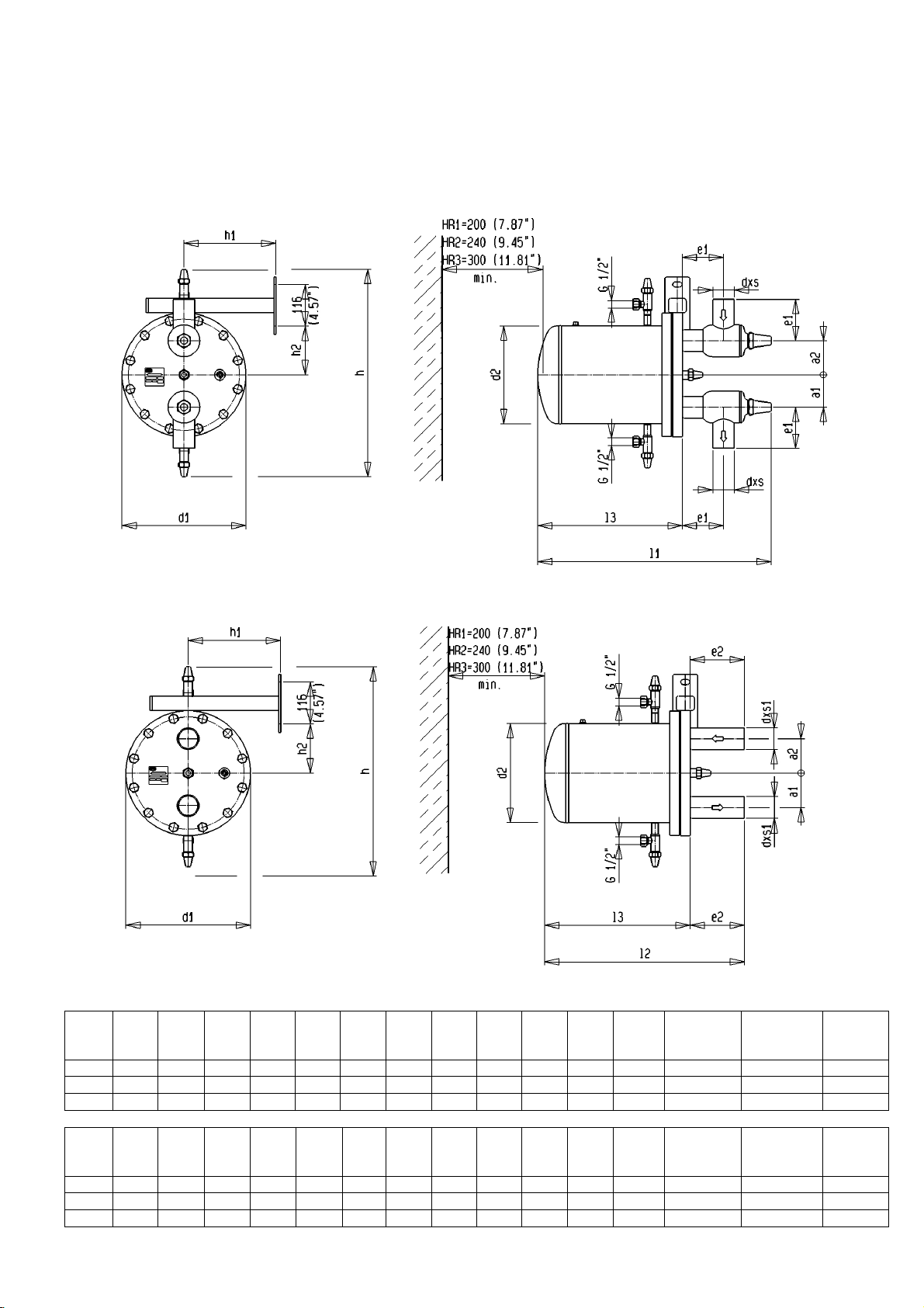
4.4 ABMESSUNGEN Fig. 3a
HR 1 - 3
4.4 DIMENSIONS
Ausführung mit Ventilen Execution with valves
Ausführung ohne Ventile, Schedule 40 Stutzen Execution without valves, Schedule 40 connections
HR1 46 53 90 160 200 139 440 425 265 200 65 390 26,9x2,3 26,9x2,9 13
HR2 50 71,5 105 160 250 194 480 445 285 200 90 450 42,4x2,6 42,4x3,6 23
HR3 90 95 115 160 345 273 640 555 395 260 135 530 60,3x2,9 60,3x4,0 54
HR1 1.81 2.09 3.54 6.3 7.87 5.47 17.32 16.73 10.43 7.87 2.56 15.35 1.06x0.09 1.06x0.11 28.6
HR2 1.97 2.81 4.13 6.3 9.84 7.64 18.90 17.52 11.22 7.87 3.54 17.72 1.67x0.10 1.67x0.14 50.7
HR3 3.54 3.74 4.53 6.3 13.58 10.75 25.20 21.85 15.55 10.24 5.31 20.87 2.37x0.11 2.37x0.16 119
17
a1
mm
a1
inch
a2
mm
a2
inch
e1
mm
e1
inch
e2
mm
e2
inch
d1
mm
d1
inch
d2
mm
d2
inch
l1
mm
l1
inch
l2
mm
l2
inch
l3
mm
l3
inch
h1
mm
h1
inch
h2
mm h mm
h2
inch h inch
d x s
mmxmm
d x s
inch
d x s1
mmxmm
d x s1
inch
Gewicht
Weight
kg
Gewicht
Weight
lb
Page 18
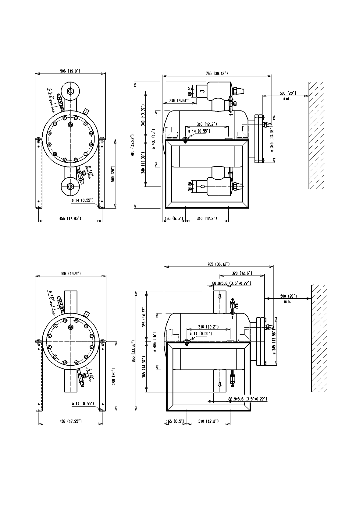
4.4 Abmessungen
HR 4
Fig. 3b
4.4 Dimensions
HR4 mit Absperrventilen am Eintritt und Austritt HR4 with stop-valves at inlet and outlet
HR4 mit Schedule 40 Anschluss-stutzen HR4 with Schedule 40 connections
18
Page 19
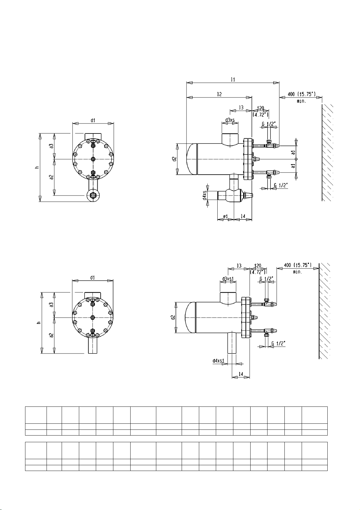
4.4 Abmessungen
Fig. 3c
HS 30 -40
4.4 Dimensions
HS30 /HS40 mit Austrittsventil HS30 /HS40 with outlet stop-valve
HS30 /HS40 mit Schedule 40 Anschlüssen HS30 /HS40 with Schedule 40 connections
a1
a2
a3
d1
mm
mm
mm
mm
HS30 90 255 180 290 219,1 114,3x3,6 60,3x2,9 115 555 510 655 460 155 127 49
HS40 147 355 262 400 323,9 168,3x4,5 88,9x5,6 155 750 685 775 585 194 154 107
d2
mm
d3xs
mmxmm
d4xs
mmxmm
e1
mm h mm
h1
mm
l1
mm
l2
mm
l3
mm
l4
mm
Gewicht
Weight
kg
HS30 3.7 10.04 7,08 11.42 8.63 4.5x0.24 2.37x0.16 4.53 21.8 20.08 25.79 18.11 6.10 5,00 108,02
HS40 5.79 14 10,31 15.75 12.75 6.63x0.28 2.71x0.22 6.1 29.52 26.97 30.51 23.03 7.68 6.06 235,89
a1
inch
a2
inch
a3
inch
d1
inch
d2
inch
d3xs1
inch
d4xs2
inch
e1
inch h inch
h1
inch
l1
inch
l2
inch
l3
inch
l4
inch
Gewicht
Weight
lb
19
Page 20
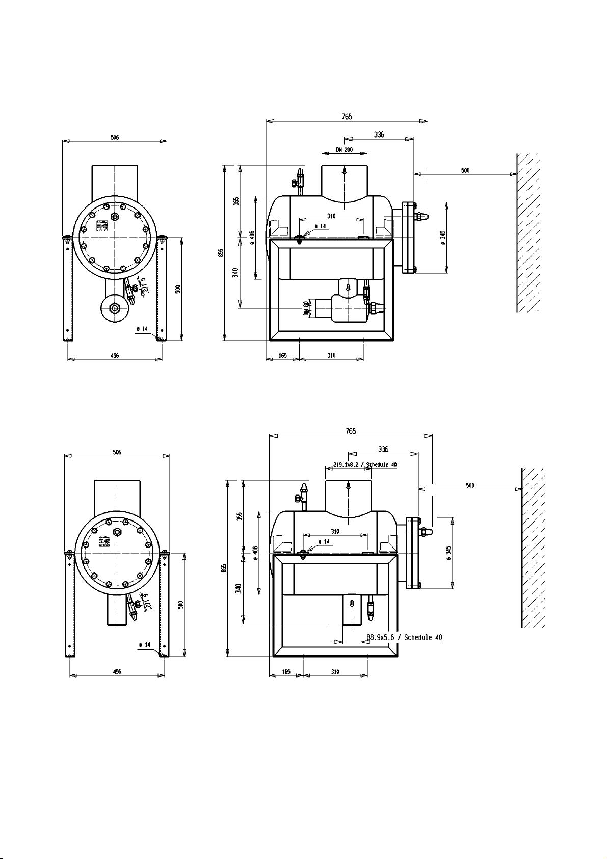
4.4 Abmessungen
Fig. 3d
HS 50
4.4 Dimensions
HS50 mit Austrittsventil HS50 with stop-valve at the outlet
HS50 mit Schedule 40 Anschluss-Stutzen HS50 with Schedule 40 connections
20
Page 21
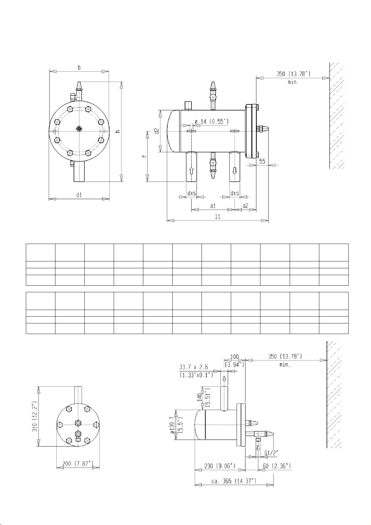
WP3HR
-
65bar
4.4 Abmessungen
WPHR / HR1BW
4.4 Dimensions
Fig. 3e WP2HR / WP3HR
a1
mm
a2
mm
b
mm
e
mm
d1
mm
d2
mm
l1
mm
h
mm
dxs
mmxmm
Gewicht
Weight
kg
WP2HR 200 100 275 230 250 194 475 460 42,4x2,6 26
WP3HR 270 140 375 275 345 273 640 545 60,3x2,9 61
270 150 375 275 355 273 650 545 60,3x2,9 68
a1
inch
a2
inch
b
inch
e
inch
d1
inch
d2
inch
l1
inch
h
inch
dxs
inchxinch
Gewicht
Weight
lb
WP2HR 7.87 3.94 10.83 9.06 9.84 7.64 18.7 18.11 1.67x0.1 57.32
WP3HR 10.63 5.51 14.76 10.83 13.58 10.75 25.2 21.46 2.37x0.11 134.48
WP3HR-
65bar
10.63 5.90 14.76 10.83 13.98 10.75 25.6 21.46 2.37x0.11 150,00
Fig. 3f HR1BW
21
Page 22
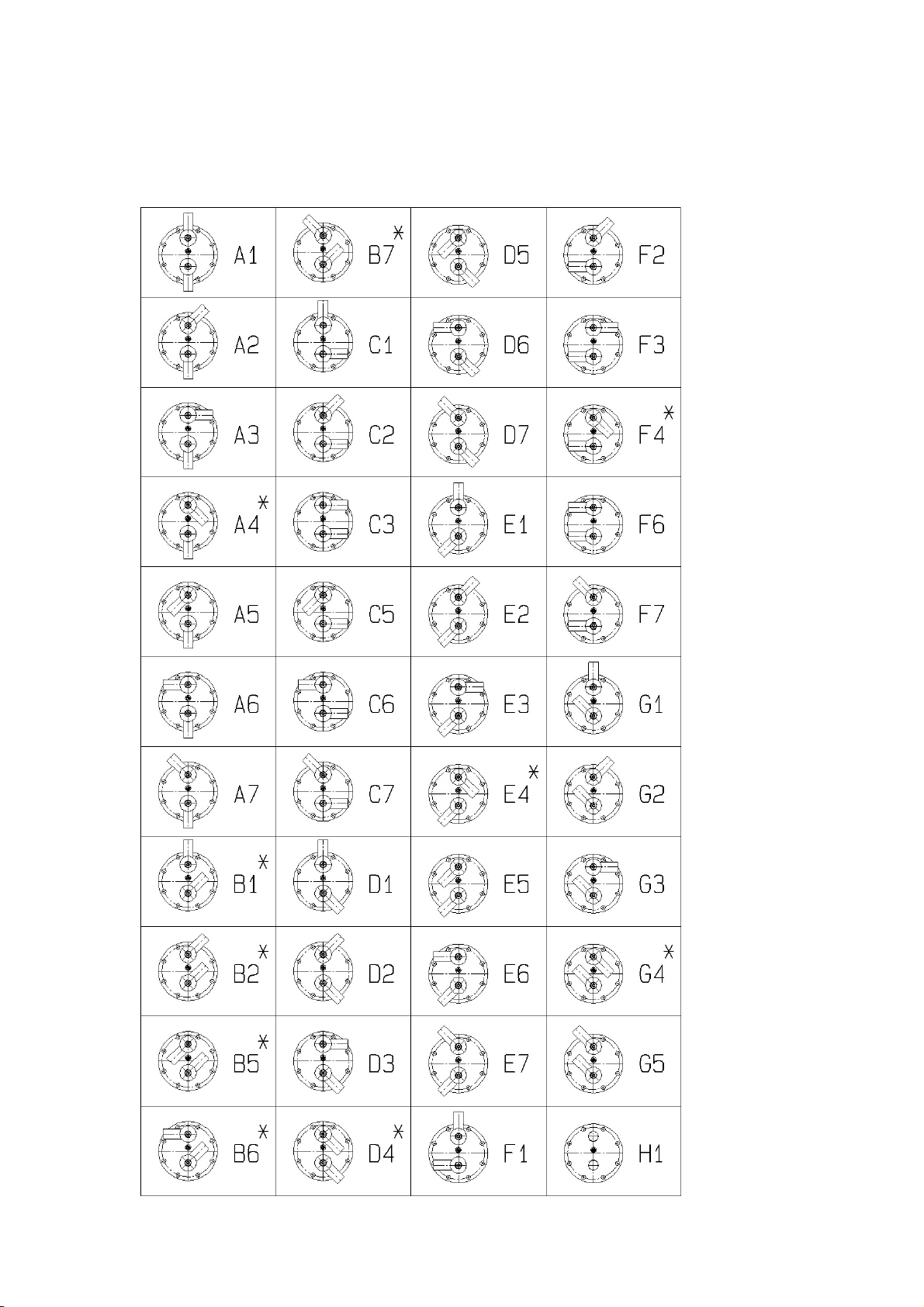
4.5 GEÄNDERTE VENTILSTELLUNGEN
Fig. 4a
HR 1 - 3
4.5 MODIFIED VALVE POSITIONS
22
Page 23
4
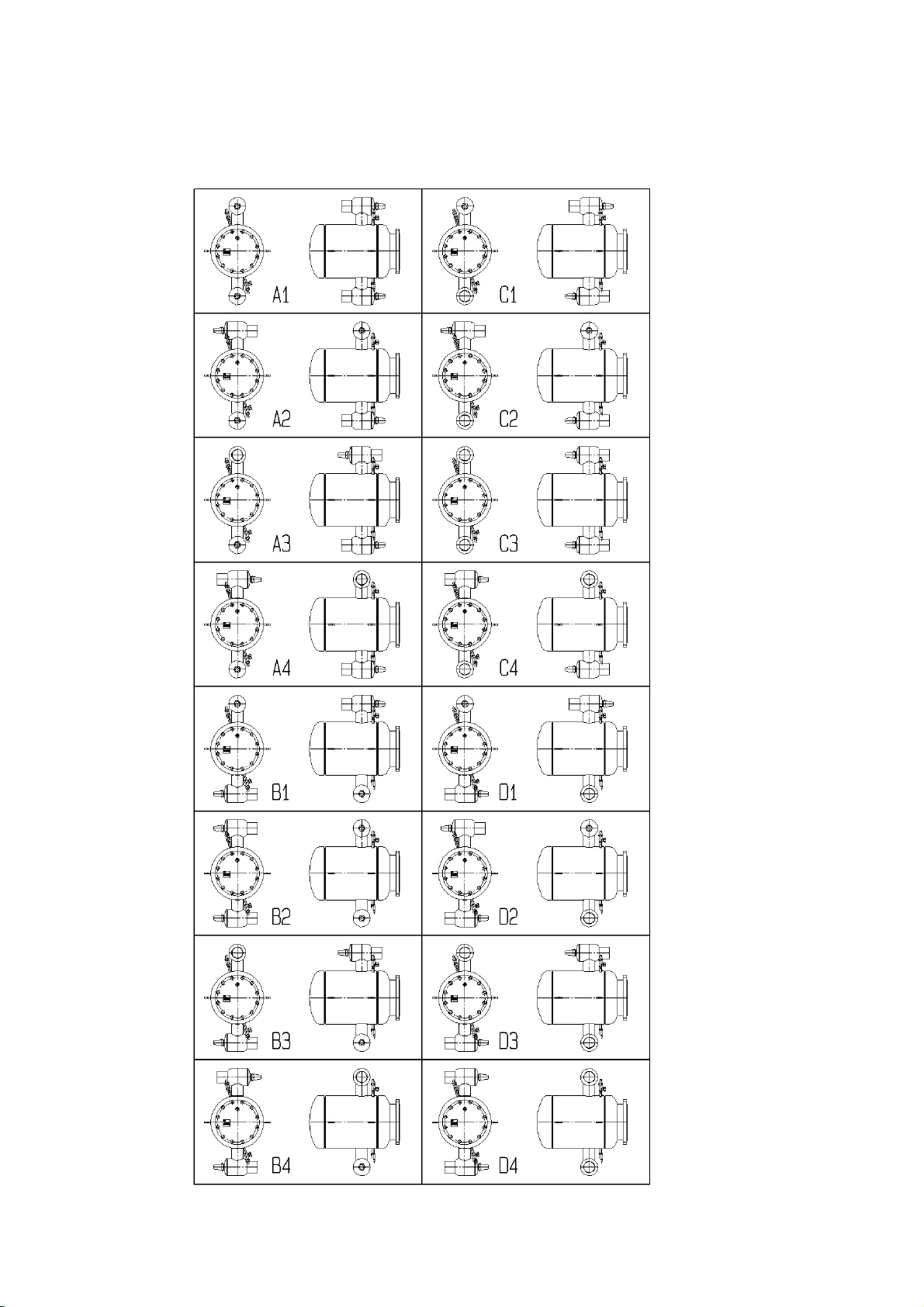
.5 geänderte Ventilstellungen
Fig. 4b
4.5 Modified Valve Positions
HR 4
23
Page 24
5. FUNKTIONSBESCHREIBUNG
Der Hochdruckschwimmer-Regler entspannt alles auf
der Hochdruckseite anfallende Kältemittel auf die Niederdruckseite, ohne jedoch Gas durchzulassen. Durch
diese einfache mechanische Methode wird eine äußerst
energiesparende Betriebsweise ohne elektrische Regelung ermöglicht.
5.1 FUNKTION INNERHALB DER ANLAGE
5.1.1 Einstufige Anlage
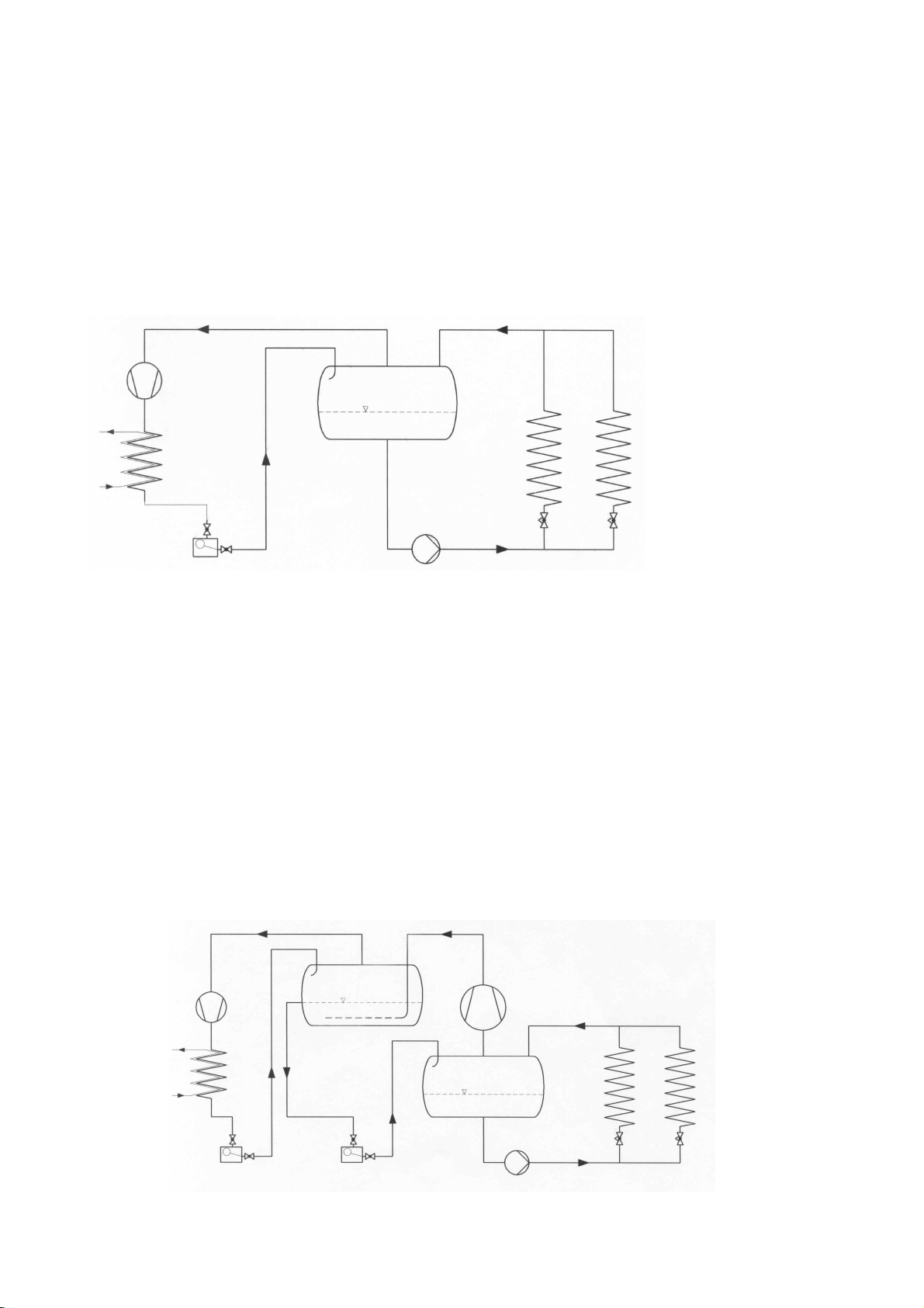
Das Prinzip der Hochdruckschwimmer-Regelung für eine
einstufige Anlage ist in Fig. 5 dargestellt.
5. DESCRIPTION OF OPERATION
The high-pressure float regulator expands all liquid refrigerant condensed on the high-pressure side of the system to
the low-pressure, but prevents any gas from flowing
through the regulator. This simple mechanical operation
enables a very energy efficient operation, eliminating the
need for complicated electrical controls.
5.1 OPERATION WITHIN THE PLANT
5.1.1 Single stage plant design
The principle of a float regulation for a single stage plant is
shown in fig. 5.
Prinzip einer einstufigen Anlage
Im Verflüssiger anfallendes flüssiges Kältemittel gelangt
in den Schwimmer und wird dort bei konstanter Enthalpie zur Niederdruckseite entspannt.
Durch die Entspannung im Austritt des Hochdruckschwimmer-Reglers befindet sich hinter dem Hochdruckschwimmer-Regler ein Flüssigkeits-/Gasgemisch,
das zum Abscheider strömt.
Vom Abscheider aus kann das Gas wieder dem Verdichter, bzw. die Flüssigkeit den Verdampfern zugeführt
werden.
Die Kondensattemperatur kann sich den äußeren Gegebenheiten entsprechend optimal anpassen, wodurch
eine sehr energiesparende Betriebsweise gewährleistet
wird. Eine Unterkühlung der Flüssigkeit ist normalerweise ausgeschlossen.
5.1.2 Zweistufige Anlage
Das Prinzip für eine zweistufige Anlage stellt die folgende Abbildung, Fig. 6, dar.
Fig. 5
Principle of a single stage plant
Any refrigerant liquid condensate that forms in the con-
denser will flow to the float regulator and will be expanded to
the low-pressure side at constant enthalpy.
As a result of the liquid expansion there is a mixture of flash
gas and liquid refrigerant in the liquid line from the regulator
to the surge drum.
The resulting flash gas will be drawn from the surge drum by
the compressor while the liquid feed to the surge drum will
be distributed to the low side evaporators.
The condensing temperature varies according to the ambient temperature conditions, allowing an energy-saving operation.
Sub cooling of the liquid is not possible at normal operating
conditions.
5.1.2 Two-stage plant design
The principle of a two-stage plant with float regulation is
shown in fig. 6.
Prinzip einer zweistufigen Anlage
24
Fig. 6
Principle of a two stage plant
Page 25
Auch hier ist ein Hochdruckschwimmer-Regler zwischen
Verflüssiger und Abscheider montiert, der das Kondensat
auf den Mitteldruck entspannt. Ein zweiter Regler wird
verwendet, um das Kältemittel zur Niederdruckseite zu
entspannen. Zweistufige Kälteanlagen mit Hochdruckschwimmer-Regelung haben einen verbesserten Wirkungsgrad und vermeiden hohe Endtemperaturen der
Verdichtung
Da der zwischen MD- und ND-Seite montierte
Hochdruckschwimmer-Regler das Kältemittel aus
dem MD-Behälter bis zu seinem Abgriffspunkt zur
ND-Seite ableitet, ist der ND-Behälter so auszuführen, dass die komplette schwankende Kältemittelmenge aufgenommen werden kann (NDSeite und Überschuss der MD-Seite!).
The system uses a float regulator between condenser
and surge drum, this expands the liquid refrigerant to the
intermediate pressure. A second regulator is used to
expand the liquid refrigerant further to the low-pressure
side of the system.
Two stage refrigeration systems with float regulation
have an improved efficiency and avoid very high gas
temperatures for second stage compression.
As all the liquid from the condenser and intermediate vessel up to the connection to the
second float regulator is passed to the surge
drum on the low pressure side, this has to be
designed to accommodate the full amount of
fluctuating refrigerant charge (low pressure side
and excess of the intermediate side.
5.1.3 Abtauen von Verdampfergruppen
Bei gängigen Abtauzeiten der Verdampfer (ca. 30 min)
reicht für die Auslegung des HochdruckschwimmerReglers eine 1,5 - 2 fache Leistung der gleichzeitig abtauenden Verdampfer aus. Sollten kürzere Abtauzeiten erforderlich sein, muss die Leistung auf das 3 – 4-fache der
gleichzeitig abtauenden Verdampfer erhöht werden.
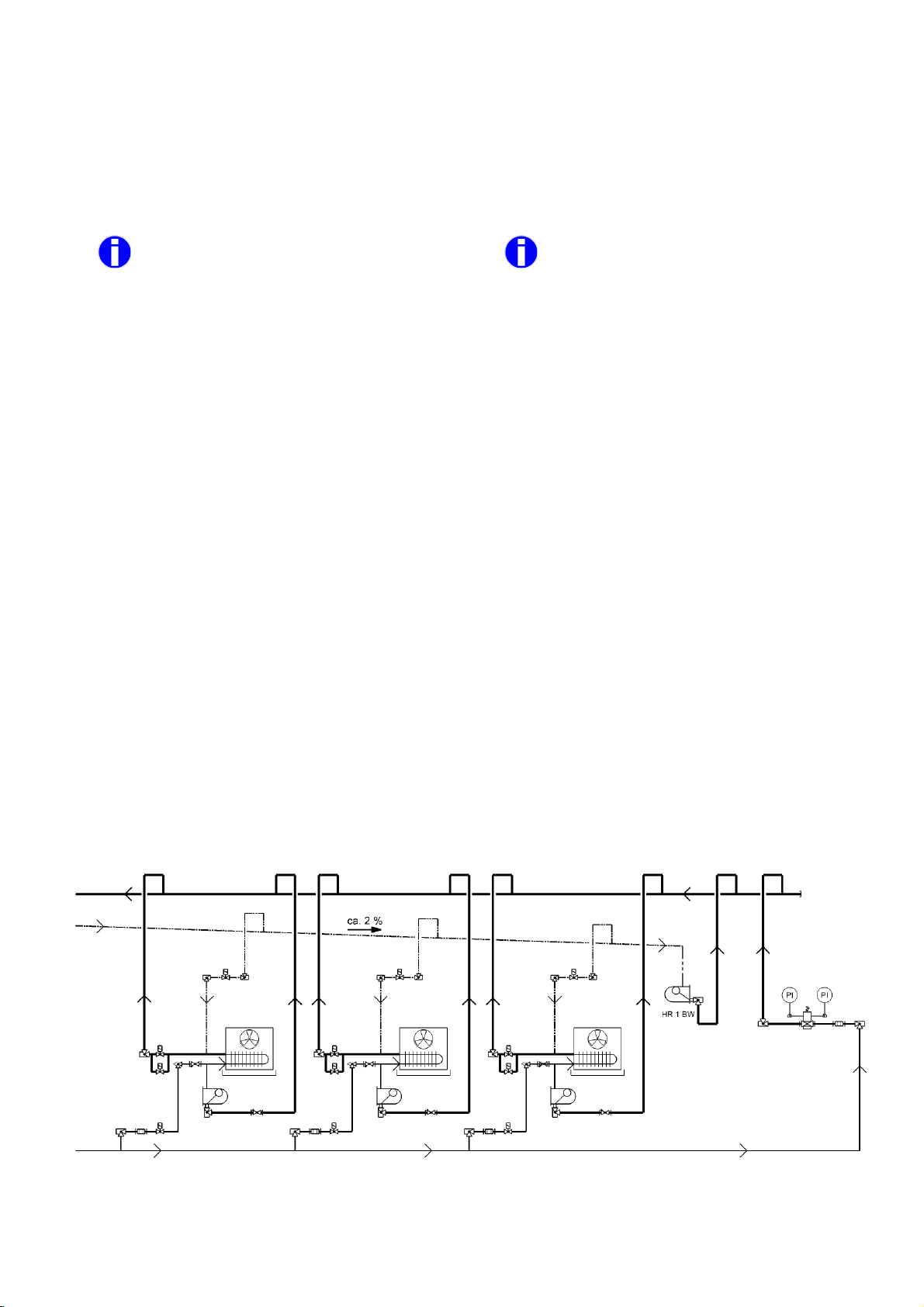
Die konventionelle Methode Verdampfer abzutauen ist in
nachfolgender Zeichnung 7a beschrieben. Sie bietet sich
an, wenn Verdampfer mit großen Leistungen eingesetzt
werden.
Dabei wird pro Verdampfer ein HochdruckschwimmerRegler vorgesehen, der das Kondensat in die Saugleitung
zurückführt. Eine Standard-Unterdruckdüse reicht in der
Regel aus, um ein Gaspolster zu verhindern.
Ein hinter dem Regler montiertes Rückschlagventil verhindert ein Rückströmen von Kältemittel, wenn einzelne Verdampfer abgetaut werden.
Diese Funktion kann auch von einem automatisch betätigbaren Ventil bzw. Kugelhahn übernommen werden.
Wenn der Druck im Normalbetrieb den Öffnungsdruck des
Rückschlagventils übersteigt (z.B. bei Einsatz von Verdampferdruckreglern), sollte auf jeden Fall ein automatisches Ventil/Kugelhahn eingesetzt werden.
5.1.3 Hot Gas Defrosting of evaporators
For common defrost periods (ca. 30 min) the high side
float regulator has to be sized for 1,5 - 2 times the ca-
pacity of the evaporators that are defrosted at the same
time. If shorter defrost periods are required the capacity
has to be increased up to 3 – 4 times the capacity of the
evaporators that are defrosted at the same time.
The conventional method of defrosting evaporators is
shown in fig. 7a. This method is used particularly for
evaporators with large capacities.
There is one high side float regulator for each evaporator
that drains condensate in the common pump return line.
A standard low pressure nozzle is normally sufficient to
avoid a gas buffer in the regulator housing.
A check valve that is mounted behind the regulator will
prevent a backflow of refrigerant when other evaporators
are defrosted.
For this function you may also use an automatic oper-
ated valve or ball valve.
If the pressure during the normal refrigeration cycle can
exceed the pressure that will open the check valve (e.g.
when using back pressure regulators) you should always
select an automatic operated valve instead of a check
valve!
Konventionelle Anordnung
Fig. 7a
Conventional defrost installtion
25
Page 26
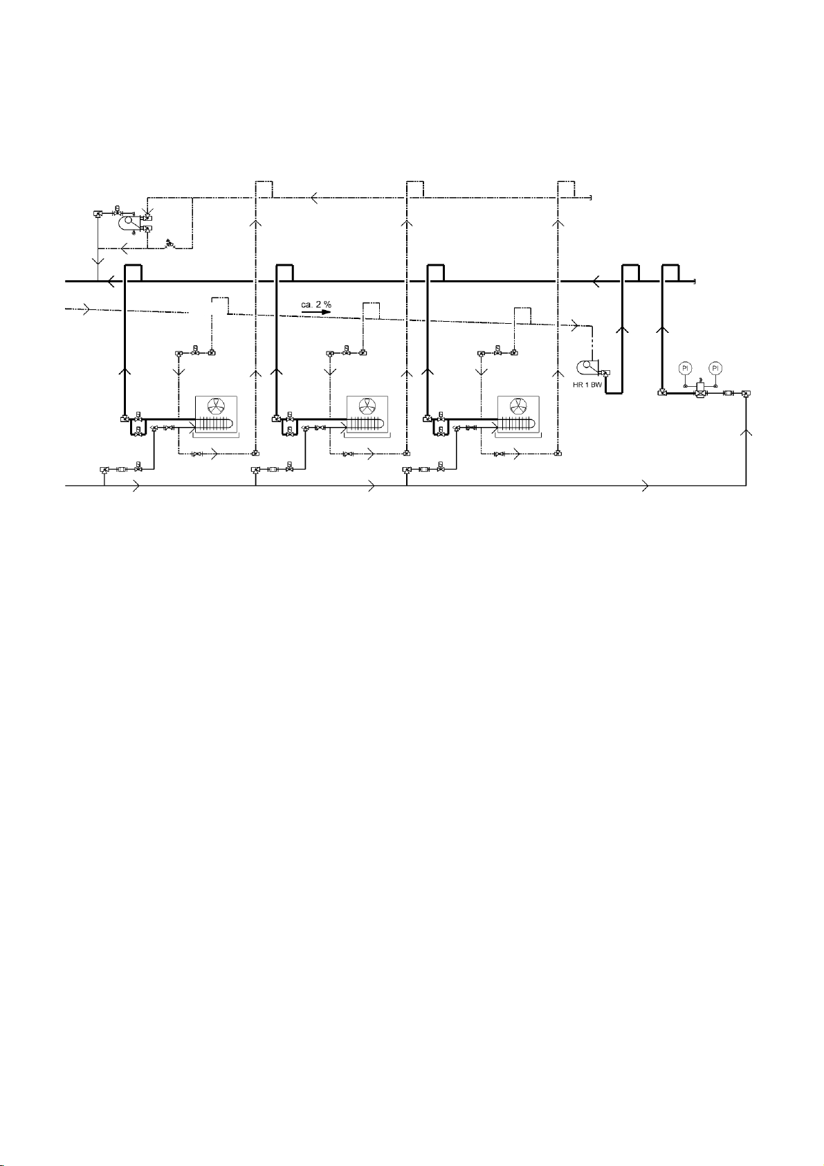
Für die schnelle Kondensatableitung beim Abtauen von
Verdampfergruppen hat sich die nachfolgende, kostengünstige Anordnung nach Fig. 7b bewährt.
ca. 2%
For fast condensate drainage of evaporators the following
cost-effective arrangement, according to fig. 7b, has worked
well.
Anordnung der Verdampfergruppen
Fig. 7b
Bei der Einbindung der Verdampfer ist darauf zu achten,
dass die Heißgasleitung mit etwa 1-2% Gefälle zum HR1
BW verlegt wird (siehe Fig. 7b ).
Der HR1BW leitet das Kondensat der Heißgasleitung ab
und verhindert so ein schlagartiges Verdampfen von RestFlüssigkeit beim Einsetzten der Heißgansabtauung.
Am Ende der Kondensatleitung soll ein Hochdruckschwimmer-Regler mit verschlossener Unterdruckdüse
montiert werden.
Wenn das Magnetventil nach Beendigung der Heißgasabtauung geschlossen wird verhindert das eingeschlossene
Gaspolster, das Flüssigkeit im normalen Betrieb durch den
Regler gedrückt werden kann.
Ein Überströmventil in einer Bypassleitung zwischen Kondensat- und Saugleitung dient der Absicherung der Kondensatleitung, falls der Druck unzulässig ansteigt.
5.1.4 HR1BW zur Ölrückführung
Alternativ kann der HR 1 BW auch für eine Ölrückführung
eingesetzt werden. Hierzu wird der Regler an der tiefsten
Stelle des Ölabscheiders montiert.
Das sich ansammelnde Öl wird dann automatisch zum
Verdichter zurückgeführt ohne Gas durchzulassen.
Da der HR1BW Öl ständig zum Verdichter zurückführt,
entfällt die Ölvorlage, d.h. es kann weniger Öl eingefüllt
werden!
Nach Stillstandzeiten kann das Magnetventil in der Verbindung zurück zum Verdichter schon nach wenigen Minuten wieder geöffnet werden, da eventuell im Ölabscheider
kondensiertes Kältemittel sofort im Betrieb verdampft.
Installation of evaporator groups
When installing the hot gas line use a gradient of app. 1 –
2% to the HR1BW according to fig. 7b.
The HR1BW will drain any condensate that is formed in
the hot gas line so that a sudden evaporation / slug of
liquid is avoided when the hot gas cycle starts.
At the end of the condensate drain line there should be a
high-pressure float regulator with closed low-pressure
nozzle
When the solenoid valve closes upon finishing of the hot
gas cycle, the enclosed gas buffer will prevent that any
liquid refrigerant is pushed through the regulator during
normal operation
Excessive pressure between the liquid condensate and
the pump return line should be avoided by use of a bypass line with an overflow valve.
5.1.4 HR1BW for oil return
Alternatively the HR1BW can be used for an oil return.
Therefore the HR1BW should be placed at the lowest
spot of the oil separator.
Any oil that accumulates will automatically be returned to
the compressor without any gas passing through.
Since oil is permanently returned by the HR1BW the oil
charge can be reduced.
After stand-still the solenoid valve in the line between
HR1BW and compressor can be opened only after a few
minutes, because any refrigerant that may have condensed will immediately evaporate during operation.
26
Page 27
5.1.5 Selbstheilungseffekt
Auf HD-seitige Sammler sollte grundsätzlich verzichtet werden:
Bei zu klein ausgelegtem Regler tritt ein Rückstau des Kältemittels ein. Dieser Rückstau bewirkt, dass sich die wirksame
Verflüssigerfläche verkleinert und der Kondensationsdruck
solange ansteigt, bis der Regler in der Lage ist, das anfallende Kondensat abzuführen. Mit zwischengeschalteten Sammlern kann diese günstige Eigenschaft nicht genutzt werden, da
zunächst der Sammler gefüllt wird, bevor sich Kältemittel im
Kondensator zurückstauen kann!
Achtung: Durch die Verlagerung des Kältemittels zur HD-Seite
(erkennbar an einer messbaren Unterkühlung des Kondensats) kann der Minimalstandsalarm auf der ND-Seite ausgelöst werden.
Wird die maximal zulässige Druckdifferenz überschritten, z.B. bei hohen Kondensationstemperaturen, kann
der Auslassmechanismus des Reglers blockiert werden!
5.1.5 Recovery Effect
The installation of a HP-receiver must generally be
avoided.
When the float regulator is selected too small, refrigerant will back-up into the condenser. This back up has
the result that the effective condenser surface will be
decreased and the condensing pressure will raise until
the float regulator is again capable to release the accumulated condensate. With a high-pressure receiver
installed in between the two components this very helpful characteristic cannot be used, since the receiver will
be filled first before any condensate will build up in the
condenser.
Caution: If too much liquid migrates to the high-pressure
side (this can be checked by sensing the sub cooling of
condensate) the llow-evel alarm of the LP surge drum
may be activated.
If the maximum allowable differential pressure is
exceeded, e.g. at high condensate temperatures,
the outlet mechanism of the regulator may become blocked!
5.2 SCHWIMMER-REGELUNG
Das in das Hochdruckschwimmer-Regler Gehäuse eintretende Kondensat bewirkt dort, dass der Schwimmkörper angehoben wird. Über eine Hebelübersetzung wird ein Schieber betätigt, der einen entsprechenden Anteil der Drosselöffnung freigibt und das Kondensat zum Abscheider ablässt.
Weil der Schwimmkörper Reibungskräfte überwinden muss,
findet ein schrittweises Verstellen der Öffnung statt.
Wenn der Flüssigkeitsstand im Schwimmer fällt wird der
Schieber über die Öffnung bewegt und verschließt so den
Auslaß. Wenn die Schwimmerkugel unten angelangt sorgen
die geläppten Oberflächen von Schieber und Auslaß für einen
dichten Abschluss. Der Auftrieb des Schwimmkörpers ist abhängig von Durchmesser und Gewicht der Kugel und von der
Dichte der abzuleitenden Flüssigkeit.
Für Kältemittel mit geringer Dichte sind die SK-Kugeln bei den
HS Reglern vorgesehen.
Beim WP HR sind die Schwimmerkugeln unten offen. Durch
Gasansammlung innerhalb der Kugel schwimmt diese auf und
gibt die Drosselöffnung frei. Aus diesem Grund dürfen die
Hochdruckschwimmer-Regler WP HR nicht unterhalb des
Verflüssigers angeordnet werden.
5.3 FUNKTION DER UNTERDRUCKDÜSE
5.2 FLOAT REGULATION
Liquid condensate flows into the regulator housing lifting
the float ball. This movement is transmitted to the moving
part of a slide valve block, which in turn proportionally
exposes the mating seat orifice releasing condensate to
the surge drum.
Since the float has to overcome friction, there is a progressive exposure of the orifice area.
.
As the liquid level drops, the slide block moves back over
the orifice closing the outlet.
When the float ball is down at its lowest position the precisely machined surfaces of slide block and orifice area
will seal tightly. Movement of the float depends on the
diameter and weight of the ball as well as the density of
the liquid refrigerant
For refrigerants with low density we have alternative SKballs to be integrated in the HS type regulators.
With the WP HR the ball float is open at the bottom. Due
to gas formation within the ball it will move upwards, exposing a part of the orifice area. This is why highpressure float regulator WP HR are not to be mounted
underneath the condenser.
5.3 FUNCTION OF THE LOW PRESSURE NOZZLE
To enable any liquid condensate to flow to the regulator
Damit anfallendes Kondensat selbstständig dem Regler zufließen kann, wäre es eigentlich erforderlich den Regler unterhalb des Verflüssigers anzuordnen. Um eine Anordnung auch
oberhalb des Verflüssigers zu ermöglichen, sind mit Ausnahme des HR1BW, alle HR und WPHR HochdruckschwimmerRegler mit einer internen Unterdruckdüse ausgestattet. Bei
HS-Reglern ist die Unterdrückdüse optional erhältlich.
Die Unterdruckdüse verbindet den Gasraum des Gehäuses
mit dem Austrittsstutzen. Aufgrund der Druckdifferenz zwischen Hochdruck- und Niederdruckseite wird Gas aus dem
Gehäuse zur Niederdruckseite angesaugt und im Gehäuse
entsteht ein leichter Unterdruck.
27
by gravity, it would be necessary to arrange the regulator
underneath the condenser.
To permit an installation with the regulator above the
condenser, all HR and WP HR float regulators, with the
exception of the HR1BW, are equipped with an internal
low-pressure. HS-regulators may also be ordered with
low-pressure nozzle (optional).
This low pressure nozzle connects the gas space in the
housing with the outlet connection. Due to the pressure
difference between high and low pressure side, the gas
is drawn to the low-pressure side resulting in a slight
under pressure in the housing.
Page 28
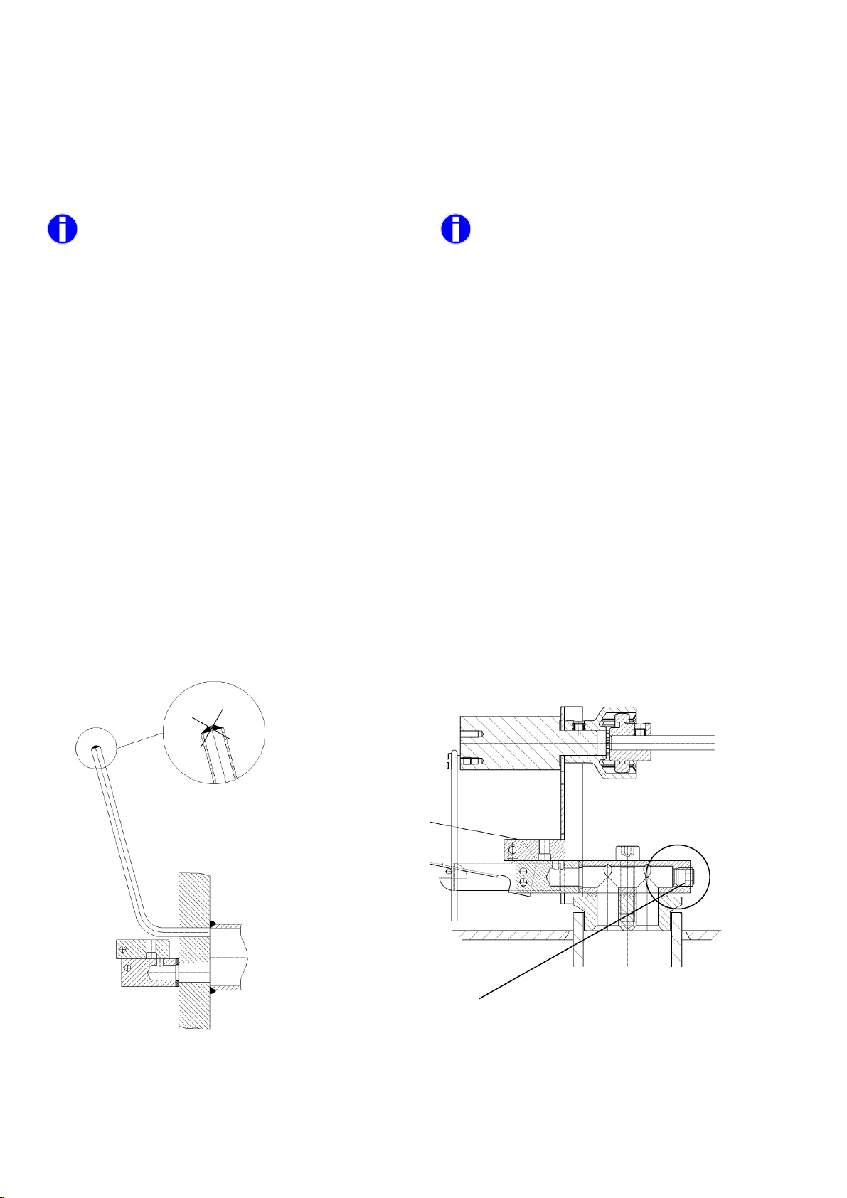
Dadurch können Gase, die sich aufgrund von Druckverlusten
bilden, bis zu 3 m Höhenunterschied und bis zu 30 m horizontale Distanz, zum Kondensator abgeführt werden.
Außerdem wird gewährleistet, dass auch ein geringer Teil
Flashgas, das sich in den Zulaufleitungen bzw. während eines
Anlagenstillstands bildet, über die Unterdruckdüse abgeführt
werden kann.
Es ist keine zusätzliche Entgasungsleitung erforderlich!
Bei Anlagenstillstand erfolgt ein langsamer Druckausgleich,
so dass sich die gesamte Kältemittelfüllung zur kältesten
Stelle verlagern kann. (Im Winter kann dies der Verflüssiger
sein.)
Wenn dieser Druckausgleich nicht erwünscht ist, muss der
Regler ohne bzw. mit verschlossener Unterdruckdüse bestellt
werden!
Die werksseitige Bemessung der Unterdruckdüse ist so ausgelegt, dass der durch Gas-bypass theoretische ermittelte
Leistungsverlust im Bereich unterhalb 1% der Nennleistung
verbleibt.
This effect allows that gases are drawn off that form over
a vertical distance from the condenser of up to 3 m and
a horizontal distance of up to 30 m.
In addition this allows the small amount of flash gas,
which can form in the liquid feed line or during plant
standstill to be bled away.
There is no additional purging line required!
During standstill of the plant system the pressure will
slowly equalize allowing the entire refrigerant charge to
transfer to the coldest part of the system. (During wintertime this can be the condenser).
If it is not desired that the pressure equalize, the regulator must be ordered without respective with closed lowpressure nozzle.
Factory selection of the low-pressure nozzle is made in
such a way that the theoretically calculated loss of capacity due to gas by-pass is less than 1% of the nominal
capacity.
5.3.1 Anlagen mit verschlossener Unterdruckdüse
Bei HR-Reglern kann die vorhandene Unterdruckdüse bei
Bedarf verschlossen werden. Standard HS Schwimmer können ohne Unterdruckdüse bestellt werden (Ausführung gemäß Fig. 8b).
Wenn der Druckausgleich im Stillstand der Kälteanlage nicht
erwünscht ist, z.B. in Verbindung mit der Ölkühlung von Ammoniak-Schraubenverdichtern, muss der HR Regler mit verschlossener Unterdruckdüse bestellt werden, siehe Fig. 8a.
(Bei einer solchen Sonderbestellung wird der Hochdruckschwimmer-Regler mit einem Aufkleber „verschlossene Unterdruckdüse“ ausgeliefert.
Verbindung zur optionalen Unterdruckdüse geschlossen.
Connection to the optional low pressure nozzle is closed.
5.3.1 Plant with closed low pressure nozzle
HR-float have always an integrated low pressure nozzle
that can be closed if necessary. Standard HS regulator
can be ordered without low pressure nozzle (execution
of the HS according to fig. 8b).
When the pressure equalization during standstill of the
refrigeration plant is not desired, e.g. in connection with
oil coolers of ammonia screw compressors, the HR regulator must be ordered with closed low-pressure nozzle,
see fig. 8a. (These special orders will be delivered with
an identifying label “closed low pressure nozzle”).
Fig.8a HR Regler mit verschlossener Unterdruckdüse
HR regulator with closed low pressure nozzle
Fig.8b HS Regler ohne Unterdruckdüse
HS regulator without low pressure nozzle
28
Page 29
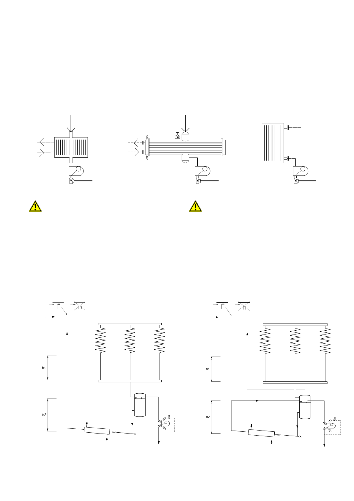
den
5.3.2 HS-Regler ohne Unterdruckdüse
Die HS Regler Modelle HS31 – HS33, HS41 – HS43 sowie
HS51 und HS53 werden ohne Unterdruckdüse ausgeliefert.
Wenn HS Regler unmittelbar unter dem Verflüssiger montiert werden, kann auf die Unterdruckdüse verzichtet wer
Eventuell entstehende Gasblasen können über die großzügig bemessene Verbindungsleitung zum Verflüssiger aufsteigen und werden dort verflüssigt.
Fig. 9a
Die Verbindungsleitung zu HS-Reglern ohne Unterdruckdüse sollte großzügig bemessen sein (gleiche
Dimension wie der Anschluß am Reglergehäuse).
Außerdem sollte die Leitung so kurz wie möglich auf
direktem Weg und ohne Widerstände verlegt werden.
Zusätzliche Bögen, Reduzierungen oder Armaturen
sollten vermieden werden. Eine Gasblase soll ungehindert zum Verflüssiger aufsteigen können
Fig. 9b
5.3.2 HS regulators without low pressure nozzle
HS regulator models HS31 – HS33, HS41 – HS43 as well
as HS51 and HS53 are delivered without low pressure
nozzle.
When the HS regulator is mounted as close as possible
underneath the condenser, there is no need for a low
pressure nozzle. Any gas bubbles can raise back to the
condenser through a generously sized connection between regulator housing and condenser, where they will
be condensed.
Fig. 9c
When using HS regulatos without low pressure
nozzle it should be sonsidered that the connection
to the condenser should have the same dimension
as the top connection of the regulator housing.
The line should be as short as possible avoiding
resistances caused by elbows, reducers or valves.
A gas bubble should be able to raise back to the
condenser.
5.3.3 Anlagen mit Ölkühlern
In Fig. 10 ist das Prinzip einer Anlage mit Ölkühler dargestellt. Die Entgasung des Reglergehäuses wird über eine
externe Entgasungsleitung vorgenommen.
5.3.3 Installations with oil coolers
Fig. 10 shows the principle installation of a plant with oil
cooler. Purging of the regulator housing has to be carried
out with an external vent line.
Fig 10a Fig. 10b
Prinzip einer Anlage mit Ölkühlern
Principle installation with oil coolers
29
Page 30

Am Einstellventil, das oben am Reglergehäuse angebracht
ist, wird eine Steuerleitung mit Magnetventil zur Niederdruckseite verlegt. (Die Größe der Steuerleitung sollte gleich
der Anschlussgröße des Einstellventils sein.) Das Magnetventil bleibt bei Stillstand der Anlage geschlossen und verhindert den Druckausgleich.
Beim Einsatz von kältemittelgekühlten Ölkühlern ist darauf
zu achten, dass immer eine ausreichende Vorlage zum
Ölkühler vorhanden ist. Der Hochdrucksammler muss deshalb oberhalb des Ölkühlers angebracht sein.
Die in Fig. 10 dargestellten Höhen h1 und h2 müssen ausreichend bemessen sein. In der Praxis hat sich gezeigt,
dass diese häufig zu gering gewählt werden: die Höhe h1
reicht dann nicht aus, um Druckschwankungen auszugleichen bzw. die Höhe h2 reicht nicht aus um den Druckverlust
in der Leitung zu kompensieren.
A separate set of controls is to be fitted from the top
purge connection. After the EE3/EE6 regulating valve a
solenoid valve has to be installed in the line returning to
the low-pressure drum. (The line size should be the
same as the regulating valve). The solenoid valve has to
be closed during plant standstill preventing equalisation
of the system pressure.
When used with refrigerant cooled oil coolers care must
be taken to ensure that a sufficient liquid refrigerant feed
to the oil cooler is maintained at all times. The highpressure receiver must therefore be positioned above
the oil cooler.
Heights h1 and h2 shown in fig. 10 have to be correctly
sized. It has been observed in practice that these
heights are insufficient. Height h1 was not large enough
to balance any pressure fluctuations and height h2 did
not exceed the pressure drop in the liquid line.
6. PLANUNGSHINWEISE
6.1 ALLGEMEINES
Die hochdruckseitige Regelung erfüllt innerhalb der Anlage
die Aufgabe der Drosselung durch Kondensatableitung. Sie
ist deshalb besonders geeignet bei Anlagen mit Zentralabscheidern- oder Verdampfern mit energiesparender Betriebsweise. Aufgrund der rein mechanischen Betriebsweise
ist die Kondensatableitung jederzeit ohne zusätzlichen Regelaufwand gewährleistet.
Im Gegensatz zur Niederdruckschwimmer-Regelung befindet sich die schwankende Kältemittelmenge im Zentralabscheider.
6.2 AUSWAHLKRITERIEN
Für die Auslegung von WITT Hochdruckschwimmer-Regler
verweisen wir auf unser Auslegungsprogramm, dass Sie auf
unserer Website www.th-witt.com runterladen können und
auf unseren Katalog: „Hochdruckschwimmer-Regler für Kälteanlagen und Wärmepumpen“.
WITT Hochdruckschwimmer-Regler sind durch folgende
Eigenschaften charakterisiert:
• Unabhängig von einer minimalen Druckdifferenz
• Unabhängig von einer minimalen Leistung
• Der max. Massenstrom ist abhängig von der Druckdiffe-
renz und der Abmessungen von Gehäuse bzw. Stutzen
• Die maximal zulässige Druckdifferenz ist abhängig von
der spezifischen Dichte des Kondensats
6.3 ANORDNUNG
6.3.1 Allgemeines
Aufgrund der Unterdruckdüse kann der Hochdruckschwimmer-Regler auch über dem Verflüssiger angeordnet werden.
Max. 3m Höhenunterschied und 30 m horizontaler Abstand
zwischen Regler und Verflüssiger können berücksichtigt
werden. Dies trifft nicht auf den HR1BW (sowie HS Regler
ohne Unterdruckdüse) zu, der nicht oberhalb des Verfüssigers montiert werden darf und auf WP HR, die nicht unterhalb des Verflüssigers montiert werden dürfen. Der WPHR
muss 1 – 3 m oberhalb des Veflüssigers angeordnet werden, damit aufsteigende Gase den Auftrieb der Schwimmerkugel unterstützen.
6. HINTS FOR PLANNING
6.1 GENERAL
High-pressure regulation within a plant is achieved by
expanding condensed refrigerant liquid. This is particularly favourable with plants that have a central surge
drum or with evaporators operating very energy efficient.
Simple mechanical operation gives a high degree of reliability, maintaining the liquid condensate drainage at alltime without further regulating effort.
In contrast to low-pressure regulators the entire fluctuating refrigerant charge is located in the central surge
drum.
6.2 SELECTION CRITERIA
For selection of WITT high-pressure float regulators
please refer to our selection program that can be
downloaded from our website www.th-witt.com and our
brochure float regulators for refrigeration plants and heat
pumps.
WITT high pressure float regulators are characterised by
the following design features:
• Independent from a minimum pressure difference
• Independent from a minimum capacity
• The maximum flow is dependent on the pressure
difference and the dimensions of housing respective
connections
• The maximum allowable pressure difference is de-
pendent on the specific weight of the liquid refrigerant
6.3 LOCATION
6.3.1 General
Due to the low-pressure nozzle design, the high-pressure
regulator can be positioned above the level of the condenser. A max. vertical distance of 3 m and a horizontal
distance between regulator and condenser of up to 30 m
are possible.
These dimensions are not valid for the HR1BW (and HS
regulators without low pressure nozzle), which cannot be
installed above the condenser and the model WP HR
that must not be installed below the condenser. The
WPHR must be mounted 1 – 3 m above the condenser
so that rising gases support the lifting of the float ball.
30
Page 31
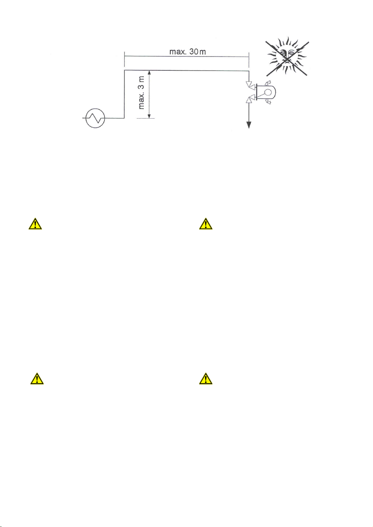
Arrangement of the high pressure float regulator
Anordnung des Hochdruckschwimmer-Reglers
Der Regler kann in der Nähe des Niederdruckteils der Kälteanlage angeordnet werden, sodass die zu isolierende
Einspritz-Leitung kurz bemessen werden kann. Allerdings ist
darauf zu achten, dass die Flüssigkeit in der Zulaufleitung
auf ihrem Weg vom Verflüssiger (Mitteldruckbehälter) zum
Hochdruckschwimmer-Regler einem möglichst geringen
Druckabfall und Wärmeeinfall ausgesetzt wird.
6.3.2 Parallelschaltung von Verflüssigern
Die Parallelschaltung von mehreren Verflüssigern an
eine gemeinsame Sammelleitung sollte auf jeden Fall
vermieden werden! Es ist empfehlenswert, hinter
jeden Verflüssiger einen separaten Hochdruckschwimmer-Regler zu montieren.
Sollte eine Parallelschaltung von Verflüssigern mit gemeinsamer Sammelleitung dennoch gewählt werden, so ist darauf zu achten, dass nur gleiche Verflüssiger parallel geschaltet werden und eine symmetrische Anordnung gewählt
wird. Dadurch wird gewährleistet, dass die Druckverluste
sowohl in den Verflüssigern als auch in den Leitungen zum
Sammler gleich sind.
Beim Einsatz verschiedener Verflüssigertypen oder bei unsymmetrische Verschaltung der Verflüssiger bedingen die
unterschiedlichen Betriebszustände, dass Kondensat in einem Verflüssiger rückstauen kann, während der andere
bereits Gas durchlässt.
Die Höhe H vom Verflüssigerauslass zur Oberkante des HDSammlers, gemäß Abb. 12a bzw. 12b, wird vom Verflüssigerhersteller angegeben. In der Regel wird eine Mindesthöhe H gemäß Fig. 12 empfohlen.
In der Praxis hat sich gezeigt, dass diese Höhe mitunter nicht ausreicht, die Schwankungen zu kompensieren! Speziell bei größeren Druckdifferenzen ist
daher die Höhe H entsprechend zu vergrößern.
Die Leitungen vom Verflüssiger sollten mit einem Bogen von
unten and die Sammelleitung angeschlossen werden. Wenn
kein Sammler eingesetzt wird, muss die Sammelleitung ausreichend dimensioniert werden um immer eine ausreichende
Vorlage bereitzustellen.
Wird ein Hochdrucksammler eingesetzt, ist die Sammelleitung von unten an den Hochdrucksammler anzuschließen,
damit die Sammelleitung immer mit Flüssigkeit gefüllt ist,
bzw. sich die Fallleitungen entsprechend füllen können.
Eine Entgasungsleitung von der Sammelleitung bzw. dem
Sammler sollte möglichst entsprechend Fig. 12 angeschlossen werden
Fig. 11
The regulator can be positioned and installed near to the
low-pressure side of the refrigerant plant, so the length of
cold piping that requires insulation can be kept to a minimum. Note: It is important that the liquid refrigerant feed
pipe work should not be exposed to high ambient temperatures or excessive pressure drop.
6.3.2 Parallel arrangement of condensers
Parallel installation of condensers with a common
liquid receiver should be avoided under all circumstances.
It is recommended to install a separate highpressure float regulator behind each condenser.
If the parallel arrangement of condensers with a common
collector has to be selected, special care must be taken
that only equally sized models of condensers are installed
in parallel and that they are arranged symmetrically.
This is to ensure the pressure drop in the condensers and
in the lines to the common liquid receiver are approximately the same.
When different condenser types are installed or an asymmetric arrangement is made the different operating conditions will result in a back up of liquid refrigerant in one of
the condensers while letting by-pass of discharge gas
through the others.
The height H from the condenser outlet to the top of the
HP collector according to fig. 12a respective 12b, will be
indicated in the manual of the condenser manufacturer. It
is commonly recommended you use a minimum height H
as indicated in fig. 12.
It has been observed in practice that this height is
sometimes not sufficient to compensate for the
fluctuations in liquid level. Particulatly with higher
pressure differences the height H has to be increased.
The lines from the condenser shall be connected with an
elbow from the bottom to the common collector line.
The common collector line should be seized generously to
make sure there is always sufficient liquid to feed the high
side float regulator.
When a main liquid header is used the connection of the
common collector line should done from the bottom to ensure the header and drain legs from each condenser circuit
are always full of refrigerant.
A purging line of the common collector line respective main
header should be executed according to fig. 12.
31
Page 32
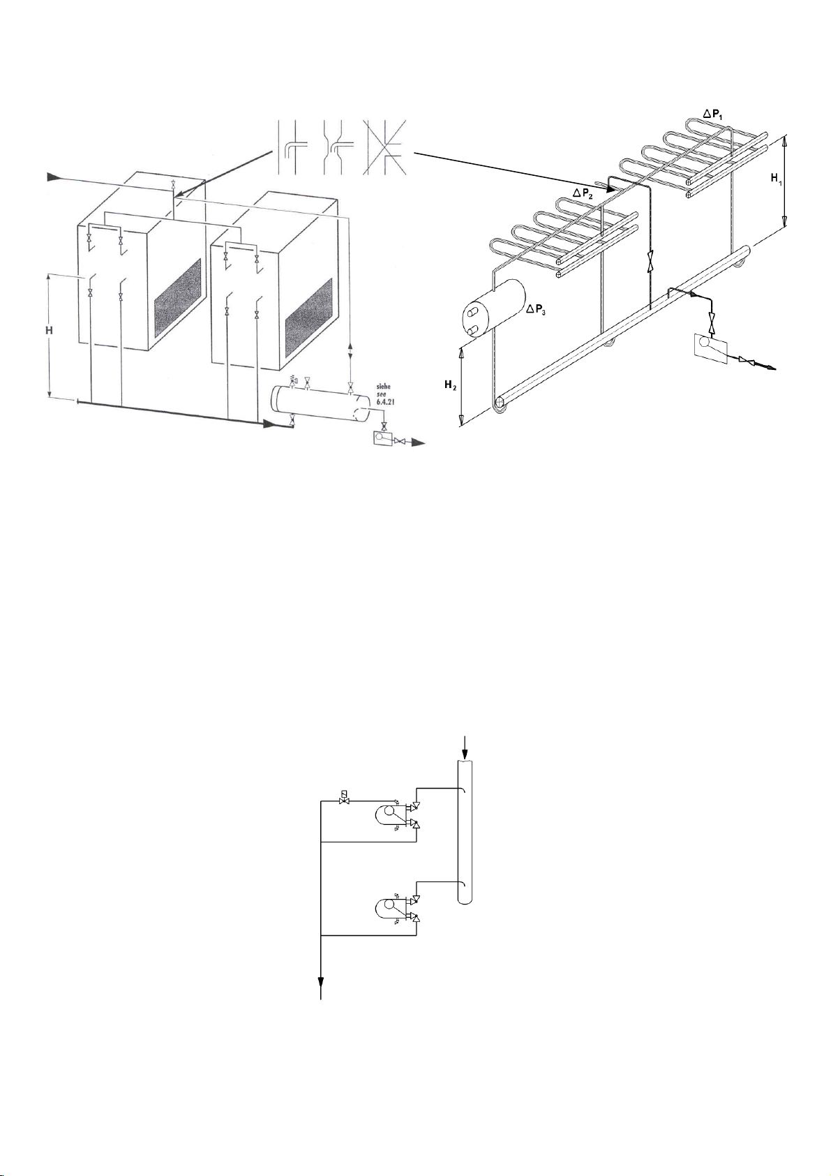
Fig. 12a
Fig. 12b
Ausführung bei parallel geschalteten Verflüssigern
Application with parallel condensers
6.3.3 Parallelschaltung der Regler
Eine Parallelschaltung der Hochdruckschwimmer-Regler ist
besonders günstig, wenn die Anlage in Teillast oder im unteren Leistungsbereich betrieben wird.
Bei einer Parallelschaltung sollten die Regler gemäß nachfolgender Abbildung übereinander angeordnet werden. Um
den Leistungsverlust durch mehrere Unterdruckdüsen zu
vermeiden, ist es empfehlenswert die Unterdruckdüse des
oberen Reglers zu verschließen und deren Funktion durch
ein Magnetventil zu ersetzen.
6.3.3 Parallel Installation of float regulator
Parallel installation of float regulators is particularly favourable in case of part load or low capacity operation.
For parallel arrangement install the regulators according to
the schematic below. To avoid a loss of efficiency with
multiple low-pressure nozzles, it is advisable to close the
low-pressure nozzle of the top mounted regulator and to
replace it with an external purging line with solenoid valve
control.
Parallele Anordnung der Regler
32
Fig. 13
Parallel installation of float regulators
Page 33
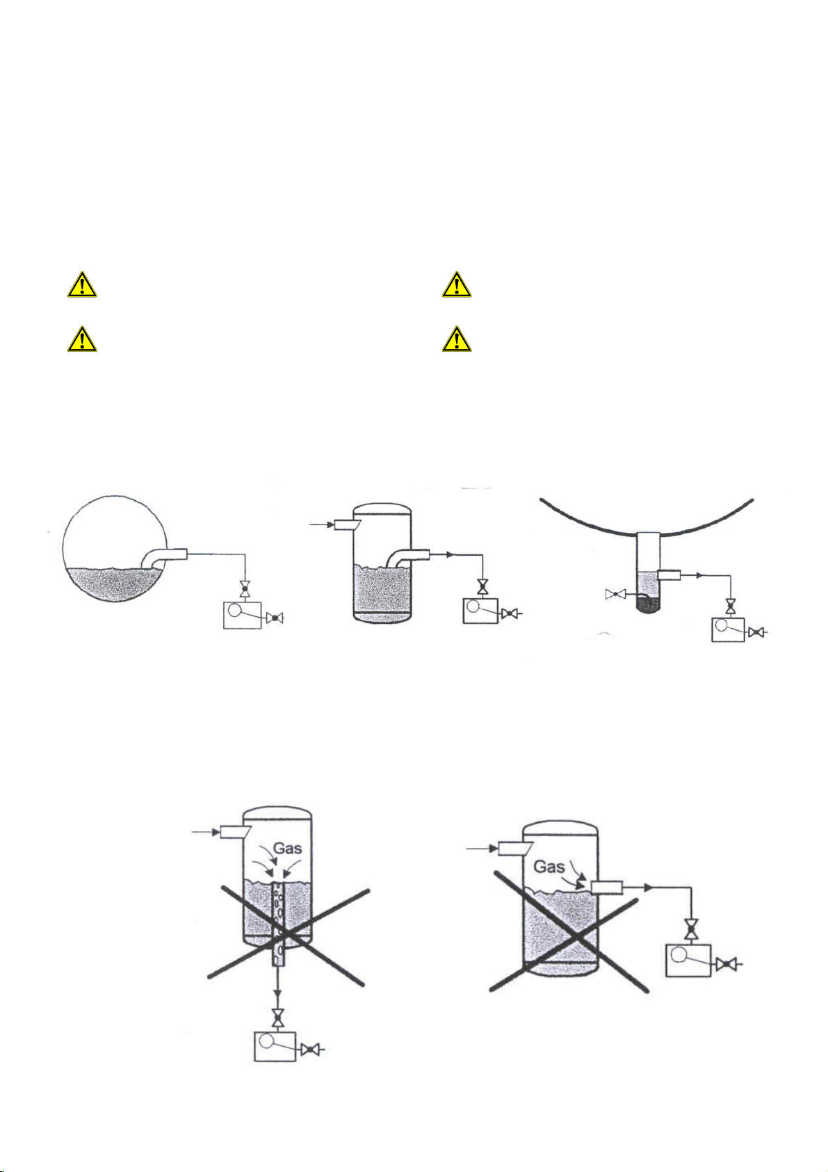
C A B
6.4 ZULAUFLEITUNG
6.4.1 Allgemein
Die Zulaufleitung ist so zu bemessen, dass die Geschwindigkeit des Kondensats unter 1 m/s bleibt. Dies ist gewährleistet, wenn die Rohrleitung den gleichen Durchmesser wie
der Anschlussstutzen am WITT-Eintrittsventil hat.
Dadurch wird verhindert, dass sich aufgrund von Reibungsverlusten zu viel Gas in der Zulaufleitung bildet.
6.4.2 Anschluss an Hochdruckbehälter
Wenn die Zulaufleitung an einen Druckbehälter angeschlossen werden soll, z.B. einen Sammler, einen Vorlagebehälter
oder an einen Zwischenkühler, so ist gemäß nachfolgender
Darstellung (Fig. 14a) zu verhindern, dass Gas angesaugt
wird.
Auf keinen Fall darf die Zulaufleitung unisoliert
durch warme Räume geführt werden, oder neben
warmen Maschinen montiert sein, noch direkter
Sonnenbestrahlung ausgesetzt werden.
Einbauten wie Filter oder Trockner dürfen auf keinen Fall vorgesehen werden!
6.4 LIQUID FEED LINE
6.4.1 General
The liquid feed line shall be sized so that the velocity of the
liquid refrigerant does not exceed 1 m/s. This will be
achieved when piping has the same diameter as the connection at the WITT inlet valve.
By maintaining this velocity you will ensure that flash gas is
kept to a minimum.
6.4.2 Connection to a HP receiver
Under no circumstances shall the liquid feed line be
installed uninsolated when piped through warm
areas, beside machines, or exposed to direct
sunlight.
Internal filters or dryers are not permitted in the
liquid feed line!
When the liquid feed line has to be connected to a pressure vessel, e.g. receiver, feed vessel or an intermediate
cooler, the installation shall follow the schematic below to
prevent any HP gas becoming entrained in the liquid line
(see fig. 14a).
Richtiger Anschluss an einen Druckbehälter
Die beiden folgenden Anordnungen sollen nicht gewählt
werden, da in Fig. 14b D aufgrund einer Strudelbildung Gas
mitgerissen wird und auch die Anordnung gemäß Fig. 14b E
Gas ansaugt.
Falscher Anschluss an den HD-Behälter
D
Fig. 14a
Fig. 14b
Proper connection to a HP vessel
The following two connection arrangements must not to be
used, as in fig. 14b D gas will be entrained due to vortexing and in fig 14b E the entrained gas will be drawn into
the liquid..
E
False connection to a high pressure vessel
33
Page 34
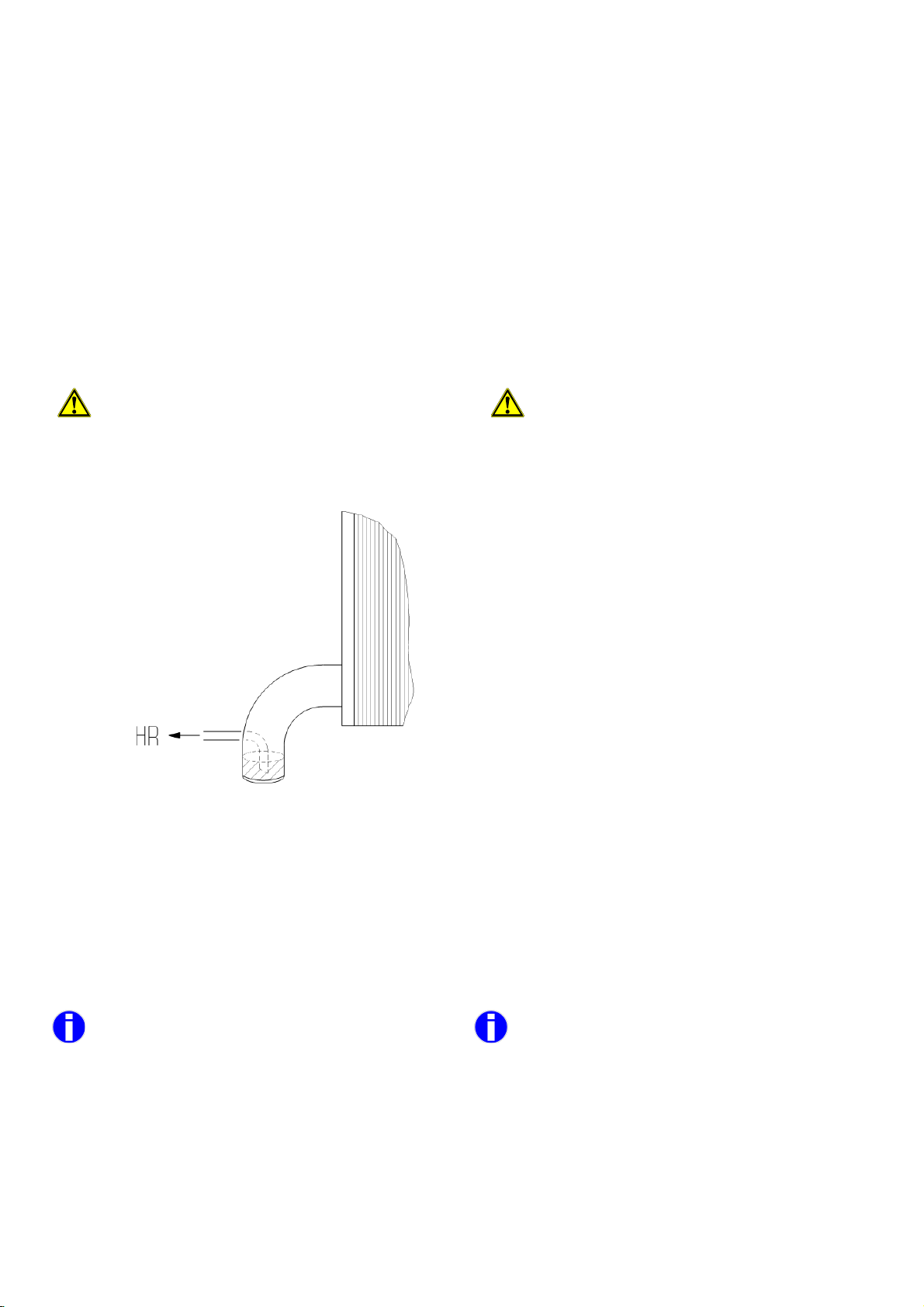
Schematic of the siphon connecting to a plate condenser
6.4.3 Automatische Ventile in der Zulaufleitung
6.4.3 Automatic valves in the liquid feed line
Automatische Ventile sind in der Zulaufleitung grundsätzlich
zu vermeiden. Sollten diese dennoch benötigt werden, empfehlen sich z.B. elektrisch oder pneumatisch betriebene Kugelhähne.
Differenzdruckabhängige Ventile (z.B. Pilotventile) sind wegen fehlender Druckdifferenz zwischen Verflüssiger und
Regler ungeeignet.
6.4.4 Anschluss an Plattenverflüssiger
Wenn kein HS-Regler ohne Unterdruckdüse verwendet werden kann (z.B. wenn der Regler nicht unter dem Verflüssiger
angeordnet werden kann), ist folgendes zu beachten:
Besonders bei Plattenwärmetauschern, die nur eine
geringe Kältemittelfüllung haben, ist darauf zu achten, dass kein Gas zu dem Regler gelangen kann.
Da der interne Druckverlust in den Kanälen des Plattenverflüssigers häufig schwankt, ist auf einen ausreichend
dimensionierten Siphon zu achten.
The use of automatic valves in the liquid feed line should
generally be avoided. If they are absolutely necessary, it
is recommended to use e.g. electrically or pneumatically
operated full bore ball valves.
Any valves depending on a pressure difference (e.g. pilot
valves) are unsuitable because of the lack of pressure
difference between condenser and float regulator.
6.4.4 Connection to plate condensers
When HS regulators without low pressure nozzle cannot
be used (e.g. the regulator cannot be placed underneath
the condenser), consideration should be given to the
following:
Particularly attention has to be paid to applications with plate-type condensers, which use a low
refrigerant charge. Care has to be taken to avoid
any gas is flowing to the regulator.
As the internal pressure difference within the plate channels fluctuates a sufficiently laid-out siphon (duck neck)
drain connection has to be used.
Gestaltung des Siphons bei Anschluss an einen
Plattenapparat
6.5 EINSPRITZLEITUNG
Hinter dem Hochdruckschwimmer-Regler befindet sich ein
Gemisch aus Gas und Flüssigkeit. Die Leitung ist mit einer
Gasgeschwindigkeit von 15 – 25 m/s auszulegen.
Die Eintrittsgeschwindigkeit in den Abscheider sollte bei
durchschnittlich 10 – 15 m/s liegen.
In der Praxis hat es sich bewährt, die Einspritzleitung 1 - 2 Nennweiten größer als die Zulaufleitung
zu wählen.
Die Länge der Einspritzleitung ist nicht kritisch, sie ist jedoch aufgrund der notwendigen Isolierung recht teuer.
Die Druckdifferenz zwischen HD und ND-Seite sollte möglichst größer als 1 bar sein um Druckverluste in der Einspritzleitung kompensieren zu können. (Nachfolgende
Gleichung erläutert dies näher.)
Fig.
15
6.5 LOW PRESSURE LINE FROM THE REGULATOR
After the regulator there is a mixture of gas and liquid refrigerant in the LP line. This line should be sized so that
the gas velocity of the liquid is 15 – 25 m/s.
The inlet-velocity into the surge drum shall not exceed an
average of 10 – 15 m/s.
It is our experience and proven practice to size
the low-pressure line from the regulator 1 – 2
seizes larger than the liquid feed line to the
regulator.
The length of the low-pressure line is not critical, but due
to the insulation required it can be expensive.
The pressure difference between HP and LP side shall
be more than 1 bar to compensate for the pressure drop
in the low-pressure line. (The following equation explains
this further)
34
Page 35
Die Druckdifferenz am Hochdruckschwimmer-Regler berechnet sich aus:
∆pHR = (pc – p0) ± ∆p
wobei ∆p
in der Regel vernachlässigt werden können,
Verluste
stat.Zulauf
- ∆p
Verluste
solange sich keine reine Flüssigkeitssäule in der Einspritzleitung befindet, da
∆p
Verluste
= ± ∆p
stat.ND-Ltg
- ∆p
Reibungsverluste
(Die Gleichungen beziehen sich ausschließlich auf das
Kondensat)
Um Flüssigkeitsschläge in Einspritzleitungen zu verhindern, sollte sie nicht in größeren vertikalen Strecken verlegt werden. Kann dies nicht vermieden werden sollten alle
ca. 5 – 8 m Flüssigkeitsfallen vorgesehen werden.
Der Anschluss der Einspritzleitung an den Abscheider
sollte so angeordnet werden, dass keine Flüssigkeit vom
Verdichter angesaugt werden kann, siehe dazu auch Fig. 5
und Fig. 6.
7. TRANSPORT UND LAGERUNG
Alle Öffnungen (Stutzen, etc.) sind mit gelben KunststoffSchutzkappen versehen, die den Eintrag von Wasser,
Schmutzpartikeln, etc. verhindern.
Zum Feststellen der Schwimmerkugel während des Transports ist die Hebelstellung (bzw. Bohrung im Hebel) im Anlieferzustand nach oben weisend (Transportsicherung).
The pressure difference at the high pressure float regulator is calculated per:
∆
pHR = (pc – p0) ± ∆p
whereas ∆p
losses
stat.supply
can normally be neglected, as long as
- ∆p
losses
there is no liquid in the injection line, because of the following equation:
∆
p
= ± ∆p
losses
stat.LP-Line
- ∆p
friction
(These equations are only for liquid refrigerant!)
To prevent liquid hammer in the low-pressure line, it
should not be installed with a large vertical riser.
If this cannot be avoided, there shall be a liquid ”U” trap
every 5 – 8 m.
The connection of the low-pressure line to the surge
drum shall be arranged to avoid any danger of liquid
being entrained in the dry suction line to the compressor
(see fig. 5 and fig. 6).
7. TRANSPORT AND STORAGE
All connections are protected with yellow plastic caps to
prevent any dirt, debris or water contaminates the regulator.
For safe transportation during delivery the float ball is
locked in position by turning the lever upwards (lever, respective the hole in the lever is facing upwards).
Die Lagerung sollte trocken und vor Schmutz geschützt erfolgen.
8. MONTAGE
Montagearbeiten an den HochdruckschwimmerReglern sind grundsätzlich nur von sachkundigem
Personal durchzuführen!
8.1 MONTAGEVORBEREITUNG
Vor Montage des Hochdruckschwimmer-Reglers sind folgende Maßnahmen zu ergreifen:
• HR auspacken und auf Transportschäden und Vollständigkeit der Lieferung überprüfen. Im Falle einer Beschädigung ist der Lieferant umgehend zu informieren.
• Vergleichen Sie die Informationen auf dem Typenschild
mit den Anforderungen bzw. der Bestellung: ist Typ
und Kältemittel korrekt, ist die Unterdruckdüse verschlossen, falls dies bestellt wurde, etc.
• Plastikschutzkappen oder andere Versiegelungen sind
erst unmittelbar vor Montage zu entfernen.
• Kontrollieren Sie ob die Rohrleitungsanschlüsse zu den
Regleranschlüssen passen.
• Es ist sicher zu stellen das die Rohrleitungen frei von
Verunreinigungen sind
Hochdruckschwimmer-Regler werden im Werk
einer Druckprüfung mit Mineralkältemaschinenöl
unterzogen. Wenn die Regler in einer Anlage eingesetzt werden, in der die Verunreinigung mit Mineralöl unzulässig sind, z. B. bei Verwendung von
Esteröl, muss der Regler zuvor mit einem Lösungsmittel ausreichend gespült werden.
Storage shall be dry and protected from any dirt or debris.
8. INSTALLATION
Any work on float regulators must be carried out
by trained and knowledgeable personnel experienced in installation and service of refrigeration
systems.
8.1 PREPARING FOR INSTALLATION
Before the float regulator can be installed the following
functions should be carried out
• Unpack the float regulator and check for damages
during shipping and the correct scope of equipment
supplied. In case of any damages inform your supplier
immediately.
• Check the information provided on the nameplate with
your order requirements, respective order confirmation: is type and refrigerant correct, is the lowpressure nozzle closed, if ordered, etc.
• Remove plastic caps or other sealing immediately
prior to (and not before) installation of the regulator.
• Check whether the regulator pipe connections match
the piping connections required.
• The piping system is to be clean and free of any mois-
ture.
The HR float regulator has undergone a pressure
test with mineral refrigerant machine oil in the
factory. If the regulator will be used in systems
where contamination with mineral oil is not allowed, i.e. in cases with ester oil in the system,
the residual oil must be removed adequately and
cleaned by use of solvents.
35
Page 36
leert und mit
The refrigeration system must be pressure tested, have
completed a successful vacuum test and be charged with
Turn the lever in automatic position (hole in the lever
8.2 MONTAGEANLEITUNG
8.2 FIXING INSTRUCTIONS
Richten Sie den Hochdruckschwimmer-Regler in waagerechter Lage aus, so dass das Typenschild lesbar ist.
Sehen Sie ausreichend Platz vor, so dass der
Schwimmerkörper ggf. ausgebaut werden kann und
die Ventile zugänglich sind.
Auf keinen Fall darf am Schwimmergehäuse geschweißt werden, da sonst die Bescheinigung sowie
die Herrestellergarantie ihre Gültigkeit verlieren!
Beim Anschweißen der Rohrleitungen an die dafür
vorgesehenen Stutzen ist auf spannungsfreie Montage zu achten!
Berücksichtigen Sie, dass sich die Rohrleitungen beim Herunterkühlen entsprechend verkürzen!
Die angeschweißten WITT-Ventile sollten beim Anschweißen halb geöffnet sein und mit einem feuchten Tuch gekühlt
werden.
Beim Anschweißen an die Stutzen des WP HR , HR4 und
HS bzw. an ohne Ventile ausgelieferten Stutzen, ist darauf
zu achten, dass der O-Ring am Austritt nicht beschädigt
wird.
Die HR-Schwimmer, ab Größe HR2 sind mit einem Nocken
für Sicherheitsventile vorgesehen.
Align the float regulator in a horizontal position, so that the
nameplate can be read.
Provide sufficient space, so that the internal float
ball can be exchanged and the valves are accessible.
Under no circumstances should any attachments
be welded to the float regulator housing. Such
welding will make the certificates and manufacturers warranty void.
Make sure the installtion is stress free when
welding the float regulator to the pipework.
It is important to consider the stress in the pipe work during system temperature pull down.
WITT valves should be half open and cooled with a wet
cloth during welding.
When welding to the connections of the WP HR, HR4, HS
or to the connections without valves, make sure the heat
of welding will not damage the O-ring at the outlet.
All HR-regulators, above size HR 2 the housing is
equipped with a safety valve connection.
Drehen Sie den Hebel für die Schwimmerarretierung
nach Abschluss der Montagearbeiten nach unten.
Das Loch im Hebel müssen nach unten zeigen für
„Automatikbetrieb“.
9. INBETRIEBNAHME
9.1 VORBEREITUNG DER INBETRIEBNAHME
Die Kälteanlage muss druckgeprüft, vakuument
Kältemittel gefüllt sein.
Die Steuereinheit darf bei der Druckprüfung nicht
dem Prüfdruck ausgesetzt werden. Daher ist der
Hochdruckschwimmer Regler nicht in der Druckprüfung einzubinden (er wurde bereits im Werk einer
Dichtigkeits- und Druckprüfung unterzogen). Sollte
eine Druckprüfung mit dem Regler erforderlich sein,
muss die Steuereinheit für die Dauer der Druckprüfung demontiert werden.
Die Ein- und Austrittsventile müssen voll geöffnet sein.
Stellen Sie sicher, dass sich der Hebel in „AutomatikPosition“ befindet (d.h.. Bohrung im Hebel zeigt nach unten).
Verschliessen sie die Ventilspindeln mit den dazugehörenden Kappen.
9. COMMISSIONING
9.1 PRIOR TO COMMISSIONING
When the installation is complete, turn the lever
downwards to unlock the transportation-securing
device of the float. The hole in the lever shall point
downwards for “automatic operation”.
refrigerant.
It is not permitted the control unit is exposed to the
high test pressure. Therefore the high side pressure
regulator should be excluded from the pressure
testing on site (it has already undergone a leak- and
pressure test at the manufacturer). If it is necessary
to include the regulator in thepressure test, the control unit must be removed during the duration of the
pressure test.
The inlet- and outlet valves must be fully open
pointing downwards).
Protect the valve spindle with the supplied cap.
36
Page 37
9.2 INBETRIEBNAHME
9.2 COMMISSIONING
Stellen Sie sicher, dass aus der Anlage sämtliche Fremdgase entfernt wurden. Es ist ratsam die Anlage bei der Inbetriebnahme noch einmal gründlich zu entlüften. (Siehe dazu
auch „Entlüften“ im Kap. 11.5).
Prüfen Sie ob die Kondensationstemperatur stabil bleibt
oder stetig ansteigt. (Wenn letzteres zutrifft muss noch einmall entlüftet werden.)
Wenn das Kondensat, das vom Verflüssiger kommt, unterkühlt ist, befinden sich voraussichtlich Luft oder andere nicht
kondensierbare Gase im System.
Überprüfen Sie beim Einsatz von wassergekühlten oder
Verdunstungsverflüssigern, dass die Temperatur nach dem
Druckausgleich nicht unter den Gefrierpunkt sinkt (Einfriergefahr).
10. BETRIEB
Der Hochdruckschwimmer-Regler arbeitet völlig selbstständig und bedarf keiner weiteren Bedienung.
11.
WARTUNG UND INSTANDHALTUNG
Der eingebaute Schieber unterliegt kaum Verschleiß und die
kontinuierliche Selbstreinigung der Schiebersteuerung
macht Wartungsarbeiten normalerweise überflüssig.
Ensure that all non-condensable gases are removed from
the system. It is recommended to purge the system thoroughly during start up. (Please refer to “Purging” in Chapter 11.5).
Check that the condensing temperature is stable or increasing slowly (if you observe it is increasing, the installation must be purged again).
If the liquid refrigerant draining from the condenser is sub
cooled, there is too much air or non-condensable gases in
the system.
When the plant stops check that the water-cooled respective evaporative condenser temperature after system pressure equalisation cannot drop below freezing point (danger of freeze-up!).
.
10. OPERATION
The high-pressure regulator operates automatically and
does not require further attention.
11. SERVICE
The low friction slide block offers low wear and continuous
self-cleaning of the orifice area, which normally requires no
further maintenance.
AND
MAINTANANCE
Vor dem Öffnen des Hochdruckschwimmer-Reglers ist dieser vom Kältemittel zu entleeren.
Wenn Wartungsarbeiten am HochdruckschwimmerRegler HR durchgeführt werden sollen, muss das
Gehäuse drucklos sein und das Kältemittel vollständig abgesaugt sein, bevor die Verschraubungen gelöst werden!
Beim Öffnen der Regler kann es zu einer plötzlichen
Verdampfung von eingeschlossenem Kältemittel
kommen! Deshalb unbedingt Schutzkleidung tragen!
Entfernen Sie auf keinen Fall alle Schrauben, wenn
noch Kältemittel oder Druck vorhanden ist.
Beim Zusammenbau des Reglers ist auf Vorhandensein
aller Dichtungen und deren Unversehrtheit zu achten. Es
wird empfohlen die Dichtungen nach jedem Öffnen auszuwechseln!
Ist die Demontage von Sicherheitseinrichtungen beim Rüsten, Warten und Instandsetzen erforderlich, haben unmittelbar nach Abschluss der Arbeiten die Remontage und Überprüfung der Sicherheitseinrichtungen zu erfolgen!
11.1 FUNKTIONSKONTROLLE
Alle Regler haben einen von außen zu betätigenden Hebel,
der ein Anheben der Schwimmerkugel ermöglicht. Dadurch
kann der Regler bewusst geöffnet werden, um dessen Funktion zu überprüfen.
11.2 AUSTAUSCH DES SCHWIMMKÖRPERS
Beachten Sie beim Ausbau unbedingt die lokalen Unfall
Verhütungs-Vorschriften. Beachten Sie insbesondere folgendes:
• Prüfen Sie Fluchtmöglichkeiten, um im Notfall schnell
die Gefahrenstelle verlassen zu können.
• Sorgen Sie aus Sicherheitsgründen für Hilfe bei der
37
Before opening the high side float regulator any refrigerant
need to taken out.
When the high-pressure float regulator HR is to be
11.1 FUNCTIONING CHECK
11.2 REPLACING THE FLOAT BALL
maintained, the housing must be completely depressurised and all the refrigerant entirely removed,
before loosening any screws and opening up!
During opening up a sudden boiling of residue refrigerant may occur. Therefore wear the required
safety clothing! Do not remove all the screws until
you are sure no residue refrigerant or pressure
exists.
Upon re-assembly take care that all gaskets are in place
and in good condition. It is recommended to replace all
gasket each time the float regulator has been opened.
If you have to disassemble any safety devices for maintenance or repair make sure that on completion the reassembly and proper functions are checked.
All float regulators are provided with a lever that can be
operated externally to lift the float. The regulator can be
opened or closed that way to check that it is functioning
correctly.
Follow all national and local safety requirements and
codes of practice when removing the float. Please take
particular care of the following:
• Check the plant room layout and exit doors so you
can evacuate the area quickly in case of an emergency.
Page 38
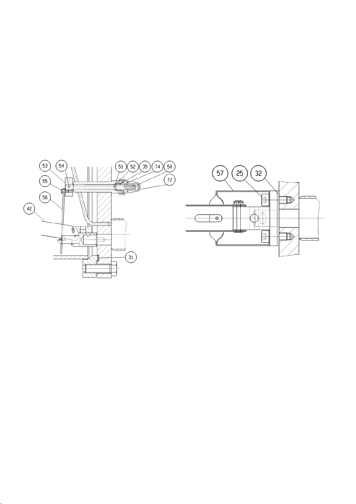
Demontage des Reglers.
Schrauben Sie Zylinderschrauben M 8 x 20, Pos. 25,
• Sorgen Sie für geeignete Schutzkleidung, mindestens
für eine Sicherheitsbrille und Handschuhe und bei Verwendung von NH3 für eine griffbereite Gasmaske.
Gehen Sie beim Austausch wie folgt vor :
• Schließen Sie das Eintrittsventil
• Arretieren Sie den Schwimmkörper, indem Sie den
Hebel nach oben drehen
• Warten Sie bis sich das Kältemittel zur ND-Seite entspannt hat
• Schließen Sie nun auch das Austrittsventil
• Lassen Sie verbleibendes Kältemittel und Öl vorsichtig
über das untere Ablassventil EA 10 GB ab
• Falls erforderlich, Spülen Sie das Gehäuse mit Stickstoff
• Seek assistance to handle and remove the float
• Wear the correct protective safety clothing, as a mini-
mum use safety goggles and gloves, in case of NH
have a safety gas mask within easy reach
When exchanging the float please carry out the following
steps :
• Close the inlet valve
• Lock the float by turning the lever upwards
• Wait until all refrigerant is released to the low pressure
side
• Now close the outlet valve
• Drain any remaining refrigerant and oil carefully
through the bottom mounted drain valve EA 10 GB
• If necessary purge the regulator housing with nitrogen
3
Fig. 16 a Fig. 16 b
HR1 – HR3 (Siehe hierzu auch Fig. 16a und 16b)
• Entfernen Sie bei den Typen HR1 bis HR 3 das Gehäuse
• Drehen Sie die Schraube M 4 x 5, Pos.55 heraus
•
aus dem Gehäusedeckel heraus
• Entfernen Sie Führungsbügel, Pos. 57 und Zugstange, Pos. 56
• Tauschen Sie die komplette Steuereinheit aus
• Ersetzen Sie Flachdichtung, Pos. 32
• Montieren Sie Führungsbügel Pos. 57, Zugstange
Pos. 56 und befestigen Sie die Steuereinheit mit den
Zylinderschrauben Pos. 25.
• Befestigen Sie Zugstange Pos. 56 mit Schraube,
Pos. 55, im Exzenter, Pos. 53
• Auf losen Sitz der Zugstange im Führungsbügel
achten!
• Montieren Sie das Reglergehäuse wieder, nachdem
die Deckeldichtung, Pos. 31, erneuert wurde.
Verfahren Sie dann gemäß Kap. 9
HR1 – HR3 (refer to Fig. 16a and 16b):
• For access remove the housing of types HR 1 to
HR 3,
• Remove screw M 4 x 5, Pos 55,
• Unscrew the cylindrical screws M 8 x 20, Pos. 52, out
of the cover
• Remove guide bracket, Pos. 57 and tow bar, Pos. 56
• Exchange the entire control unit
• Replace the gasket, Pos. 32
• Re-assemble guide bracket, Pos. 57, tow bar, Pos. 56
and fix the control unit with the cylindrical screws Pos.
25
• Secure the tow bar, Pos. 56 with screw, Pos. 55 in the
excenter, Pos. 53
• Pay attention to the tow bar, it should be seated
loosely in the guide bracket
• Always re-install the regulator housing using a new
cover gasket, Pos. 31.
Proceed according to chapter 9 for commissioning and
start-up.
38
Page 39
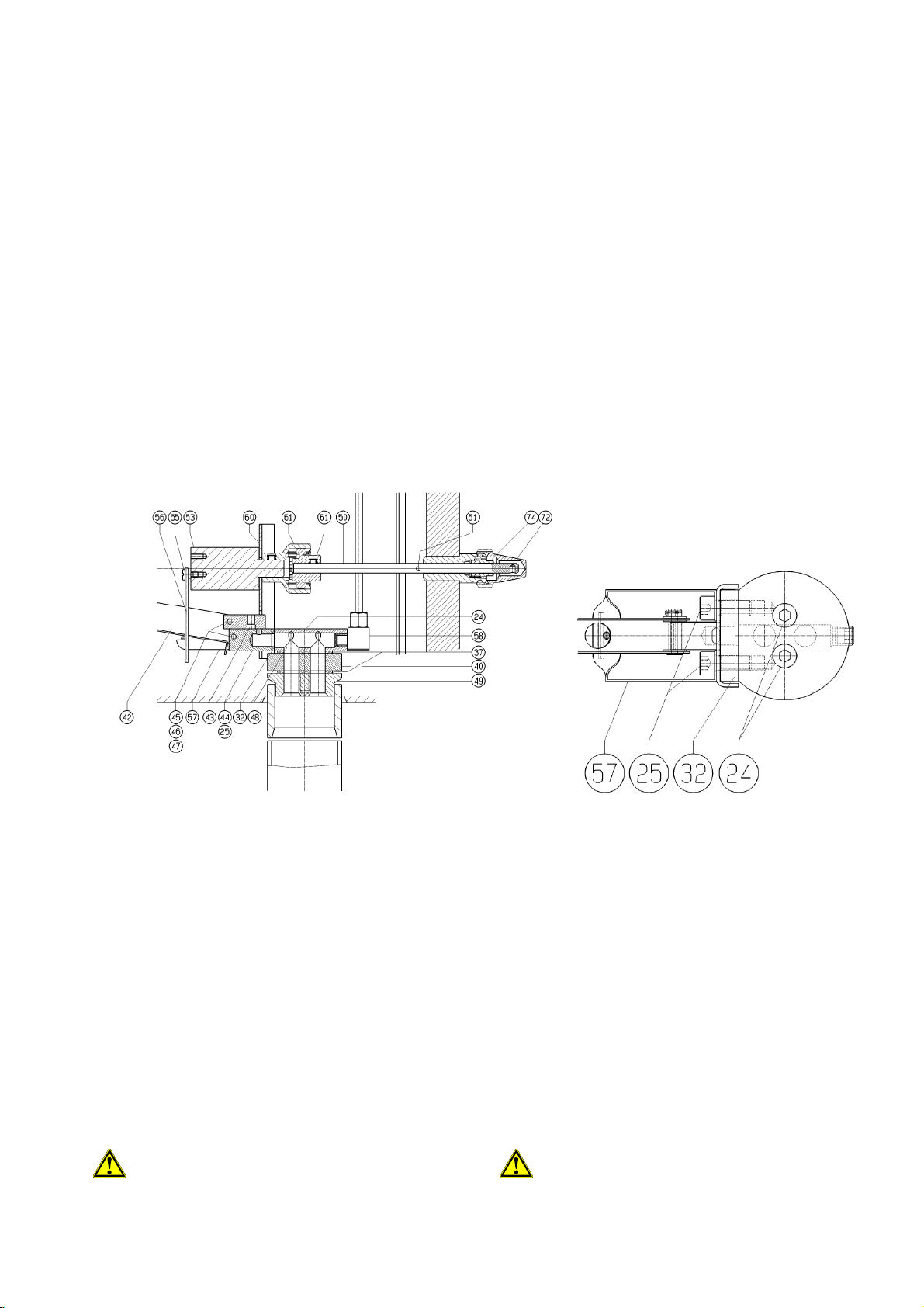
log Pos. 25 aus Fig. 16b) kann die Steuereinheit
w
Dabei wird der Hebel für die Funktionskontrolle aus
ving screws,
HR4 und HS50 (siehe dazu Schnittzeichnung 2b und 2d)
• Um den Deckel-Flansch, Pos. 11, abnehmen zu
können muss zunächst die Schutzkappe, Pos. 72
sowie die Stopfbuchse, Pos 74, des Hebels entfernt
werden.
• Schrauben M16x50, Pos 21 entfernen und den Deckel-Flansch abnehmen
• Durch Lösen der beiden Innensechskant-Schrauben
(ana
entfernt und ausgetauscht werden.
• Tauschen Sie beim Zusammenbau die Dichtung der
Steuereinheit (analog Pos. 32 aus Fig. 16b) sowie
die Deckeldichtung, Pos. 31 aus.
Verfahren Sie gemäß Kap. 9.
HR4 and HS50 (see also sectional drawings 2b and 2d)
• In order to take the cover flange, pos. 11 off, you need
to first remove the protective cap, pos. 72 and unscre
the gland, pos. 74 of the lever.
• Remove the cover plate hexagon screws, pos. 21 and
take the cover off
• Remove the two hexagon socket screw (similar to pos.
25 of fig. 16b) and you can take the entire control unit
out and exchange it.
• Always replace the gasket of the control unit (similar
pos. 32 of fig, 16b) und the cover-gasket during reassemby.
Proceed per chapter 9.
Fig. 16 c Fig. 16 d
HS30 – HS40/ WPHR (siehe Fig. 2c, 2e sowie 16 c, 16
HS30 – HS40/ WPHR (see fig. 2c, 2e and fig. 16c, 16d)
d)
• Entfernen Sie den Deckelflansch, Pos. 11, indem
Sie die Schrauben Pos 21 entfernen.
•
der Kupplung gelöst
• Durch Entfernen der Zylinderschrauben, Pos. 25
kann die komplette Steuereinheit entfernt und ausgetauscht werden.
• Ersetzten Sie die Dichtungen der Steuereinheit,
Pos. 37 sowie des Deckel-Flanschs, Pos 31 beim
Zusammenbau des Reglers
Verfahren Sie gemäß Kap. 9
11.3 AUSTAUSCH DER HEBELPACKUNG
Zum Austauschen der Packung sollte das Reglergehäuse grundsätzlich drucklos gemacht werden
• Take the cover flange, pos 11, off by remo
pos 21.
• When removing the cover flange, the lever will be re-
moved from the coupling
• Remove the two hexagon socket screwsM, pos. 25
and you ran remove and exchange the entire control
unit
• Always replace the gasket of the control unit, pos. 37
and the gasket of the cover flange, pos. 31 when reassembling the regulator
Proceed per chapter 9
11.3 REPLACING THE LEVER PACKING
Please make sure the regulator housing is depressurised before replacing the packing.
39
Page 40
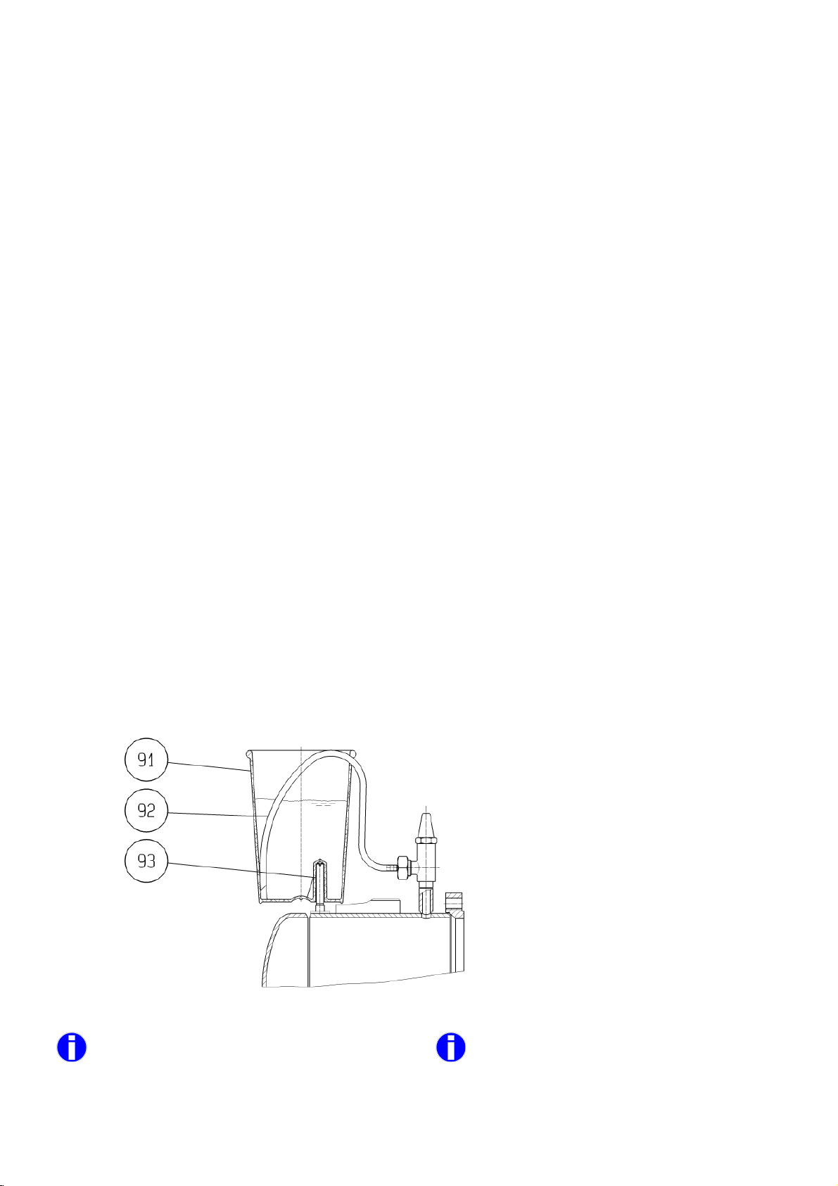
Die Packung kann ausgetauscht werden ohne das Reg-
Dazu wird nach Entfernen der Schutzkappe, Pos.
72, die Stopfbuchse Pos. 74 herausgedreht und die
EE6 HR4, HS50
lergehäuse zu öffnen.
•
Packung Pos. 35 gewechselt.
• Danach die Stopfbuchse Pos. 74 wieder einschrauben und auf Dichtheit prüfen.
You can replace the lever packing without opening the
regulator housing.
• After removal of the protective cap, pos. 72, unscrew
the gland, Pos. 74 and replace the packing Pos. 35.
• Re-assemble the gland, Pos. 74 and check for leak-
ages
11.4 AUSTAUSCH DER VENTILPACKUNG
Die Ventile dichten rückwärts, d.h. im voll geöffneten
Zustand können die Packungen ausgewechselt werden.
Dennoch ist es empfehlenswert das Reglergehäuse zuvor drucklos zu machen (siehe 11.2).
Der Austausch der Packung am Hebel darf nur wie oben
beschrieben vorgenommen werden!
11.5 ENTLÜFTUNG
Luft oder andere nicht kondensierbare Gase können sich
sehr schädlich auf die gesamte Anlage und insbesondere den Hochdruckschwimmer-Regler auswirken. Nahezu
alle Probleme können darauf zurückgeführt werden.
Eine gute Entlüftung ist daher wichtig.
Wenn die Anlage häufig entlüftet werden muss oder das
Eindringen von Luft nicht vermieden werden kann, z.B.
wenn Gleitringdichtungen von Verdichtern im Vacuum
laufen, ist eine automatische Entlüftungseinrichtung sehr
zu empfehlen!
Das nachfolgend (Fig. 17) dargestellte WITT-Zubehör
(kann optional bestellt werden) wird zur Entlüftung genutzt. Es besteht aus einem Wasserbehälter, der auf
den Regler aufgesetzt werden kann und einem Schlauch
mit ½“ Gewindeanschluss.
Schrauben Sie den Gewindestift Pos. 93 an der dafür
vorgesehenen Stelle ein (beim HS sowie HR 4 im
Flansch). Setzen Sie den Wasserbehälter Pos. 91 auf
und befestigen Sie den Schlauch Pos.9 2 an dem Entlüftungsventil EE3/EE6. Nachdem das Gefäß mit Wasser
gefüllt wurde, kann das Einstellventil EE3/EE6 vorsichtig
geöffnet werden.
11.4 REPLACEMENT OF THE VALVE PACKING
The valves can be back seated which means the stem
packing can be replaced in a fully open position.
It is still recommended that you depressurise the regulator
housing before carrying out this work (see 11.2)
The replacement of the lever packing has to be carried out
as decribed above (11.3).
11.5 PURGING
Air or any other non-condensable gases can harm the
entire refrigeration plant, particularly the high-pressure
float regulator. Most of the difficulties experienced are
caused by this particular problem. Efficient purging is
therefore very important.
When purging is necessary regularly or air intake cannot
be excluded, e.g. shaft seals of compressors are operating
in vacuum, an automatic purger is highly recommended.
The following sketch (fig. 17) shows the optional WITT gas
purge equipment designed to be used for correct purging.
The equipment consists of a special water container that
can be positioned on the float and a hose with ½”
threaded connection.
Screw in the threaded pin, Pos.93, at the intended location
(at the HS and HR4 in the flange). Place the water container, Pos. 91 on the pin and connect the hose, Pos. 92,
to the purge valve EE3/EE6 at the top. After the container
has been filled with water you can carefully open the regulating valve EE3/EE6.
Entlüftungseinrichtung für HR / HS
Solange Luftblasen bzw. nichtkondensierbare Gase aufsteigen, befindet sich noch Luft in der Anlage.
Achtung: Ammoniak ist in Wasser sehr gut löslich
und erzeugt keine Blasen.
40
Fig. 17
EE3 HR1-HR3, HS30-HS40
Optional purge device HR / HS
As long as air or non-condensable gas bubbles
continue to rise to the surface the housing is
being purged.
Attention:Ammonia is very good soluble in water
and creates no bubbles.
Page 41
Die Entlüftung ist auf jedenfalls vorsichtig vorzunehmen, da
das Wasser während des unter Umständen länger dauernden Vorgangs verdampfen kann und dann Ammoniak austreten kann. Wenn der Regler an einer frostgefährdeten
Stelle montiert ist, könnte das Wasser einfrieren.
Purging must be carried out carefully as the water may
over a period of time evaporate allowing ammonia to
atmosphere also. The regulator should only be fitted with
this air purger in a frost-free location to avoid the water
freezing.
Die Entlüftung darf nur unter Aufsicht erfolgen!
Im Anschluss ist das Wasser z.B. mit Lackmuspapier zu
prüfen und ggf. zu neutralisieren, bevor es in die Kanalisation eingeleitet werden darf
11.6 ERWEITERUNG DER UNTERDRUCKDÜSE
Die Bohrung der Unterdruckdüse ist werkseitig so bemessen, dass der durch den Gas-Bypass theoretisch ermittelte
Leistungsverlust unter 1% der Nennleistung bleibt. Bei üblicher Leitungsdimensionierung sollten die Gase, die sich auf
einer Entfernungen bis zu 30 m und Höhenunterschiede von
bis zu 3 m bilden, abgeführt werden.
Bei erhöhtem Gasanfall ist es möglich, die Unterdruckdüse
etwas zu erweitern, indem die Öffnung schrittweise aufgebohrt wird.
Zuvor sollten Sie sicherstellen, dass die Anlage ausreichend
entlüftet wurde!
Der Leistungsverlust der Anlage erhöht sich durch
das Aufbohren der Unterdruckdüse.
Das Gehäuse wie zuvor beschrieben entleeren und drucklos
machen, bevor die Schrauben gelöst warden
Nach Abnahme des Deckels/Gehäuses kann die Funktion
des Reglers gut beobachtet und geprüft werden.
11.6 ENLARGING THE LOW PRESSURE NOZZLE
Purging should only be carried out under supervision!
Upon completion of purging, the water should be
checked and neutralized if required before safe disposal.
The hole of the low pressure nozzle is delivered from the
work shop in such a way that the theoretical calculated
value of the capacity loss due to the gas-bypass is less
than 1% of the nominal capacity. With common design of
the piping system any gases that may form over a distance of up to 30 m and height differences of up to 3 m
shall be drawn off.
When increased gas formation occurs it is possible to
increase the low-pressure nozzle orifice size by drilling it
out step by step.
Before carrying out this modification please make sure
the plant has correctly been purged!
The efficiency of the plant will fall the more the
low-pressure nozzle orifice is increased.
The housing should be drained and purged as described
before, before any srews are loosened.
Upon taking the cover/housing off, the function of the
regulator can be observed and checked.
Die Bohrung am oberen Ende des Röhrchens stellt die
eigentliche Unterdruckdüse dar.
Bei HR1-3 Reglern ist das Röhrchen am Deckel befestigt,
beim HR4, WPHR und den HS-Reglern kann das Röhrchen
aus der Verschraubung gelöst werden.
Es empfiehlt sich die Bohrung bei Bedarf schrittweise zu
vergrößern.
Wenn der Hochdruckschwimmer-Regler häufig im Teillastbereich eingesetzt wird, kann es sinnvoll sein, die Unterdruckdüse zu verkleinern.
12. FEHLERSUCHE
Trotz des einfachen mechanischen Prinzips der Hochdruckschwimmer-Regelung kommt es bei ausgeführten Anlagen
gelegentlich zu Problemen.
Erfahrungen haben gezeigt, dass in den meisten Fällen eine
zu große Gasmenge im Reglergehäuse das Ansteigen des
Flüssigkeitsniveaus behindert und deshalb die Schwimmerkugel nicht aufschwimmen kann.
Ein Schauglas mit kommunizierenden Verbindungen zum
Entlüftungs-/Ablassventil, vorübergehend montiert, kann
Aufschluss über den Füllstand im Reglergehäuse geben.
Die häufigsten Fehlerursachen sind im folgenden näher erläutert:
The hole (orifice) on the top of the small tube works as a
low pressure nozzle.
For HR1 – 3 the small tube is connected to the cover,
with HR4, WPHR and HS-regulators you disassemble
the tube from the screw connection.
It is recommended to increase the hole step by step.
If the high-pressure float regulator is operated mainly
under part load conditions, it is possible to restrict the
low-pressure nozzle orifice diameter.
12. TROUBLE SHOOTING
Although the float regulation is a simple mechanical design in some cases problems occur in refrigeration
plants.
Our long term experience has shown that in nearly all
cases an increased amount of flash gas in the housing
will have the effect of lowering the liquid level making it
difficult for the ball to rise
A temporary side glass with branch connections at the
inlet-/outlet valves can be used to check the liquid level
within the regulator housing.
The most common reasons for installation problems are
explained in the following chapters:
41
Page 42

to be realised as mentioned earlier the installed height H
12.1 LUFT IN DER KÄLTEANLAGE
Bei großem verdampferseitigem Inhalt der Kälteanlage wird
oft eine Restmenge an Luft unterschätzt, die trotz des Evakuierens vor der Inbetriebnahme in der Anlage verbleibt. Bei
NH
gelangt die Luft zwangsläufig in das Schwimmergehäu-
3
se und kann hier die Unterdruckdüse überfordern.
Eine Entlüftung, wie in Kap. 11.5 beschrieben, schafft in den
meisten Problemfällen Abhilfe.
12.2 GASBILDUNG IN DER ZULAUFLEITUNG
Es kann verschiedene Gründe für dieses Problem geben:
• eine knappe Leitungsdimensionierung,
• das Vorhandensein von Einbauten wie z.B. Filtern,
• eine ungewöhnlich hohe Platzierung des HR über
dem Verflüssigerausgang oder
• eine unisolierte Leitungsführung in heißer Umge-
bung.
All dies kann dazu führen, dass ein zu großer Dampfanteil in
der Zulaufleitung gebildet wird, der die Unterdruckdüse
überfordert.
Wenn die oben genannten Ursachen nicht beseitigt werden
können, ist es möglich, die Unterdruckdüse durch schrittweises Aufbohren so zu erweitern, dass die Dampfmenge abgeführt werden kann (siehe Kap. 11.6).
12.3 PARALLELSCHALTUNG VON VERFLÜSSIGERN
ei der Parallelschaltung von Verflüssigern in eine gemeinsame Sammelleitung wird häufig beobachtet, dass unterschiedliche Strömungswiderstände der Verflüssiger zu einer
Gasbildung in der Leitung zum HochdruckschwimmerRegler führt.
Die Temperaturen am Austritt der einzelnen Verflüssiger
sind zu überprüfen. Wenn eine Unterkühlung des Kondensats in einem Verflüssiger festgestellt werden kann, dann
staut sich Kondensat im Verflüssiger zurück. Die Anlage
arbeitet dann instabil und beeinträchtigt so die Funktion des
Hochdruckschwimmer-Reglers.
Eine Flüssigkeitssäule am Austritt der Verflüssiger gemäß
Kap. 6.3.2 soll die unterschiedlichen Druckverluste ausgleichen. Wie bereits erwähnt, sind die eingeplanten Höhen in
manchen Fällen nicht ausreichend und müssen ggf. entsprechend vergrößert werden.
Sind die oben genannten Maßnahmen nicht durchführbar
oder nicht erfolgreich, so muss für jeden Verflüssiger ein
separater Hochdruckschwimmer-Regler vorgesehen werden.
12.1 AIR IN THE REGRIGERATION SYSTEM
With plants where large internal volumes exist on the
evaporator side there are often quantities of remaining
air and non-condensable gases in the system that are
often underestimated. When using NH3 the air will automatically collect in the float regulator housing. This volume of gas will exceed than capability of the lowpressure nozzle.
Purging according to chapter 11.5 will resolve the problem in most cases.
12.2 GAS FORMATION IN THE LIQUID FEED LINE
There are several causes of this problem:
• The liquid feed line has been sized too small
• There are internal filters, etc,
• The regulator is positioned too high above the
condenser
• The liquid supply line is installed uninsulated in
warm plant room environment
All these will contribute to an unacceptable level of flash
gas in the liquid feed line, causing the low-pressure nozzle to become overloaded.
If the above-mentioned conditions cannot be changed it
is possible to increase the low-pressure nozzle orifice
diameter so the gas can be released (see chapter 11.6).
12.3 PARALLEL OPERATION OF CONDENSERS
With parallel installation of condensers in a common feed
line to the float regulator it has often be observed that the
different line pressure drops causes flash gas formation
in the feed line to the high-pressure float regulator.
Check the temperatures at each condenser outlet.
If you observe sub cooling of the liquid refrigerant at one
of the condenser outlets this will indicate that liquid is
backing up inside the condenser. The entire plant is then
operating in an unstable condition effecting the proper
functioning of the high-pressure float regulator.
With the pipe work layout using a liquid head in the down
leg of each condenser circuit according to chap. 6.3.2 the
different pressure drops can be compensated. But it has
in some cases will not sufficient and should be increased
accordingly.
If the above-mentioned modifications cannot be achieved
or do not have the desired effect, each condenser must
be equipped with its own separate high-pressure float
regulator.
12.4 LUFTGEKÜHLTE VERFLÜSSIGER
Der oben beschriebene Effekt tritt auch bei luftgekühlten
Verflüssigern auf, wenn die einzelnen Rohrreihen nicht
gleichmäßig beaufschlagt werden, weil z.B. eine Seite von
der Sonne angewärmt wird oder die Rohrleitungen unterschiedliche Druckverluste aufweisen.
Durch Drosseln am Eingang jeder Rohrreihe lassen sich die
unterschiedlichen Druckverluste ausgleichen.
42
12.4 AIRCOOLED CONDENSER
The above flash gas formation can occur with air-cooled
condenser installations. Where separate banks of tube
rows are loaded differently, , e.g. if sunshine warms up
part of one side or if the tube banks have different pressure drops.
By regulating each pipe row the different pressure drops
can be compensated for.
Page 43

12.5 PLATTENVERFLÜSSIGER
Bei Plattenverflüssigern besteht die Verbindung zwischen
Eintritt und Austritt aus dünnen Kanälen, die häufig unterschiedlich belastet sind. Ein ausreichend dimensionierter
Siphon ist hier besonders wichtig. (Siehe Kap.6.4.4)
12.6 HD-SAMMELBEHÄLTER
Die Einbindung eines HD-Sammlers verhindert den erwünschten Selbstheilungseffekt, der in Kap. 5.1.5 beschrieben wird.
12.7 EINSATZ VON ÖLKÜHLERN
Beim Einsatz von Hochdruckschwimmer-Reglern mit verschlossener Unterdruckdüse in Verbindung mit kältemittelgekühlten Ölkühlern ist besonders darauf zu achten, dass
immer eine ausreichende Flüssigkeitsvorlage im HDSammler zur Verfügung steht. Der Hochdruckbehälter sollte
so bemessen sein, dass ca. 5 min der Ölkühler mit Flüssigkeit aus der Vorlage versorgt werden kann, bevor Kondensat von den Verflüssigern nachfließt.
Achtung: Bei Anlauf der Verdichter kann die Flüssigkeitsvorlage sehr schnell absinken.
Beim Einbinden des Reglers gemäß 10b ist speziell darauf
zu achten, dass kein Gas in den Regler gelangen kann (siehe dazu Kap. 6.4.2)
Häufig kommt es beim Anlaufen der Verdichter zu einem
Kältemittelmangel, d.h. dem Hochdruckschwimmer-Regler
fließt kein Kältemittel zu. Es wird ein Blockieren des
Schwimmkörpers unterstellt, da sich der Regler abkühlt und
mitunter die Leitung zum Magnetventil bereifen kann.
Ein Bereifen der Magnetventilleitung ist jedoch kein Indiz
dafür, dass das Schwimmergehäuse mit Flüssigkeit gefüllt
ist. Durch Drosselung des Kältemittelzuflusses zum Ölkühler
kann ggf. eine ausreichende Vorlage im HD-Sammler erreicht werden.
12.5 PLATE TYPE CONDENSER
For plate in shell type condensers with thin channels
that are loaded unequally from an internal hot gas connection between inlet a properly sized siphon is extremely important (see chapter 6.4.4)
12.6 USE OF HP LIQIUD RECEIVERS
The use of a high-pressure receiver in the feed line will
slow down or stop the self-recovery effect that is explained in chapter 5.1.5.
12.7 USE OF OIL COOLERS
When high-pressure float regulators with closed lowpressure nozzles are used in systems with refrigerant
cooled oil coolers you must ensure that there is always
sufficient liquid refrigerant in the HP receiver.
The high-pressure receiver should be sufficiently sized
so that the oil cooler can be supplied with refrigerant for
at least 5 min., before refrigerant is returned from the
condensers.
Caution: Be aware under certain start-up conditions of
the system the surge drum can rapidly empty of refrigerant.
When the regulator is installed per fig. 10b particular care
should be taken that no gas can enter the regulator (see
therefore chapter 6.4.2)
It has been observed during start-up there is a lack of
refrigerant liquid feed to the high-pressure float regulator.
When a blockage of the float ball is suspected, i.e. as the
regulator is cold and the line to the solenoid valve is becoming frosted.
Note: A frosted line to the solenoid valve does not necessarily indicate that the housing is filled with refrigerant.
By throttling the refrigerant flow to the oil coolers with
regulating valves it may be possible to achieve the required feed from the HP receiver.
43
Page 44
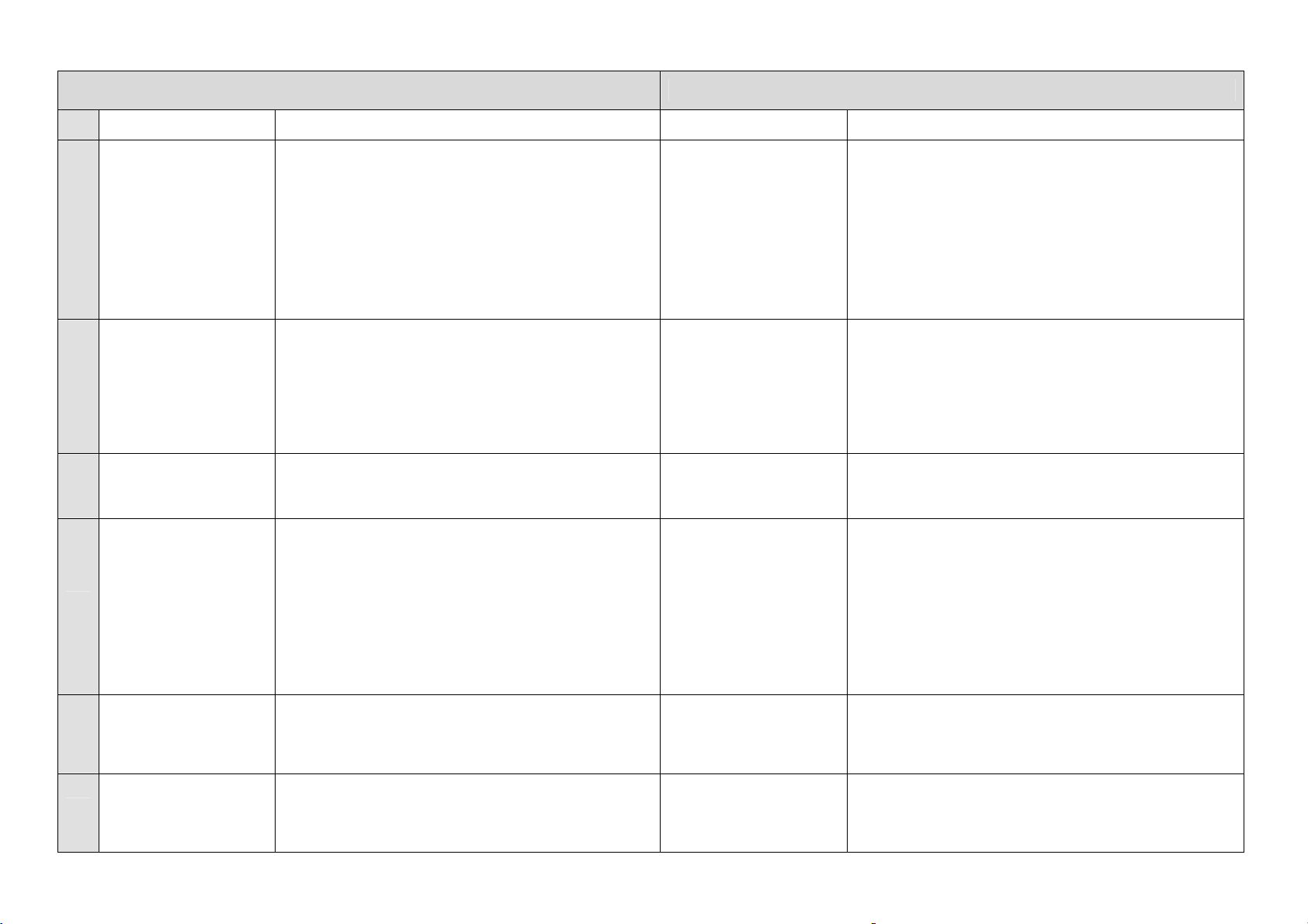
Regulator does not open
Nr.
1
2
3
4
5
6
44
Erscheinung
Regler öffnet nicht im
Automatikbetrieb
Regler schließt nicht
Verflüssigungsdruck
zu hoch ohne Rückstau
Zu hoher Verflüssigungsdruck durch
Rückstau
Stark schwankender
Druck auf der NDSeite
Minimalstandalarm auf
der ND-Seite
STÖRUNGSANALYSE:
Ursachen und Behebung
- Zu viel Luft im System
- Zu klein dimensionierter Regler?
- Eintritts-/Austrittventil verschlossen?
- Zu große Druckdifferenz?
- Unterdruckdüse zu klein oder blockiert?
- Feuchtigkeit im System, Unterdruckdüse zugefro-
ren?
- Schieberersteuerung z.B. durch Ablagerung oder
Korrosion blockiert
- Schwimmerkugel defekt
- falsche Schwimmerkugel (ggf. austauschen)
- Transportsicherung des Hebels (Knebel bzw. Loch
im Hebel muss nach unten weisen)
- Schiebersteuerung verschlissen (ggf. austauschen)
- Öffnung der Unterdruckdüse zu groß (oder bei
Anschluss einer Magnetventilleitung nicht verschlossen worden)
- fehlende Wärmeabfuhr am Verflüssiger
- zu klein dimensionierter Verflüssiger
- zu große Kälteleistung im Anfahrzustand
- Luft in der Anlage (siehe Kap 12.1)
- Dampfbildung in der Zulaufleitung (siehe Kap. 12.2)
- Verflüssiger parallel angeordnet (siehe Kap. 12.3)
- Einsatz von Plattenverflüssiger siehe Kap. 12.5)
- Mangelhafte Ölkühlerfunktion (siehe Kap. 12.7)
- Zu große Widerstände in der Zulaufleitung (siehe
Kap. 6.4)
- Zu großer Höhenunterschied vor dem Regler (ggf.
Unterdruckdüse vergrößern)
- zu geringe Kältemittelfüllung
- hohe Reibkräfte an der Schiebersteuerung (Innen-
teile auf Ablagerungen bzw. Korrosion prüfen)
- Regler wurde überdimensioniert
- siehe Pkt. 4
- Verflüssiger im Winter mit Kältemittel gefüllt (ein-
zelne oder alle Verflüssiger absperren)
- Zu geringe Kältemittelfüllung
Symptom
during automatic operation
Regulator does not
close
Condensing pressure is
too high without back-up
Too high condensing
pressure because of
back-up
Heavy fluctuating pressure on the LP side
Minimum level alarm on
the LP side
TROUBLE SHOOTING
Possible Causes
- Too much air in the system
- Too small selected regulator?
- Closed inlet-/outlet valve?
- Too high pressure difference?
- Low-pressure nozzle too small or blocked?
- Moisture in the system, now pressure nozzle frozen?
- Slide regulation is blocked, e.g. with debris or due to
corrosion
- Float ball is damaged
- False float ball (can be exchanged)
- Transport safety device blocks the float ball (hole in
the lever shall face down)
- Slide block is worn (can be exchanged)
- Opening of the low pressure nozzle is too big (or:
when connecting a solenoid valve line the low pressure nozzle is not closed)
- Condenser does not transfer any heat
- Too small condenser
- Capacity is too large during start-up
- Air in the system (see chap. 12)
- Gas in the supply line (see chap. 12.2)
- Parallel condensers (see chap. 12.3)
- Use of plate type condenser (see chap. 12.5)
- False connection of oil coolers (see chap. 12.7)
- Resistance in the supply line is too high (see chap.
6.4)
- The vertical distance is too high (the low pressure
nozzle can be enlarged)
- Too low refrigerant charge
- High friction at the slide block (look for any debris or
corrosion)
- Float regulator is too big
- See point 4
- Condenser is backed up with refrigerant (isolate one
or more condensers)
- Too low refrigerant charge
:
Page 45

45
Page 46
TH.WITT
Kältemaschinenfabrik
GmbH
Lukasstraße 32 •52070 Aachen, Germany
Tel. +49 (0)241 1 8208 - 0
Fax +49 (0)2 41 1 82 08- 49
[email protected]
W3510-6.01 c–4.0702
www.th-witt.com
 Loading...