

Page 1
WITELCOM CPN-55-20 Installation instructions
Mounting the enclosure
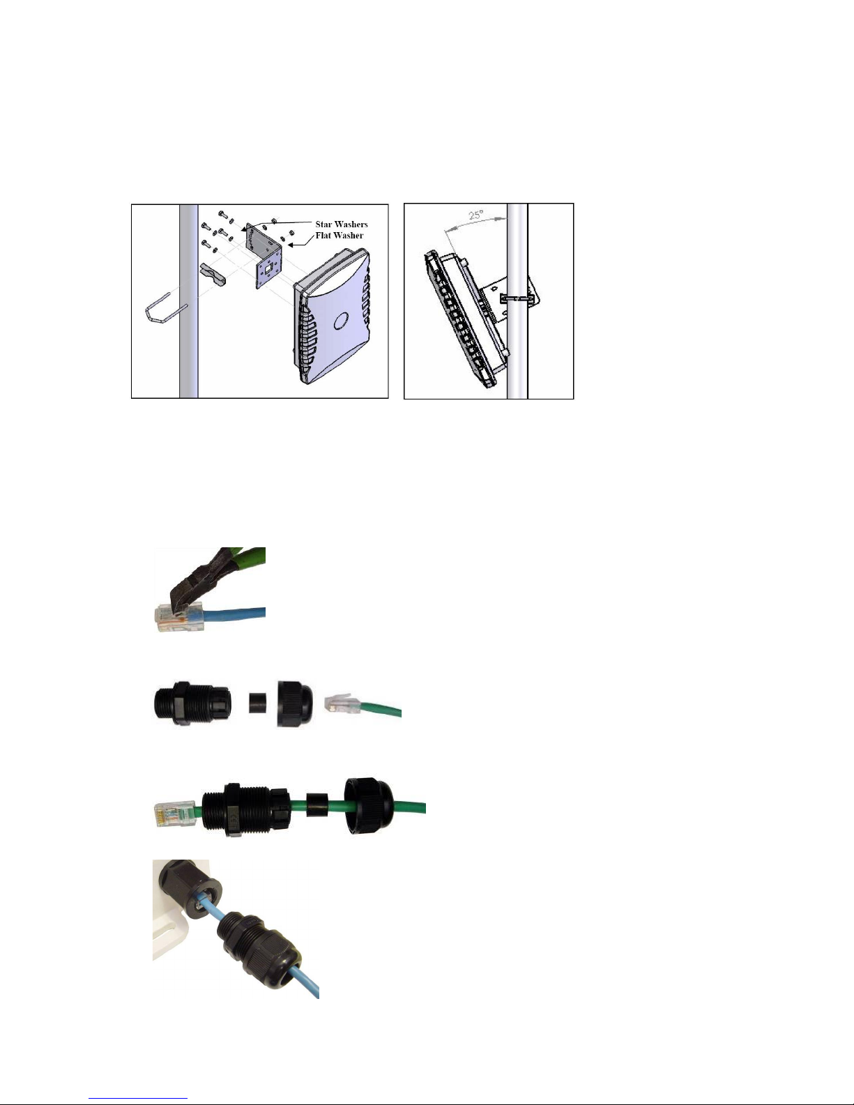
1. The enclosure must be mounted for vertical polarisation. Refer to polarisation sticker on the back of the enclosure.
2. Attach the L bracket to the antenna by means of the four M6 x 16mm bolts provided. The figure 8 illustrates this for
vertical polarisation.
3. Attach the enclosure to a mast (diameter 32 - 50mm) using the Econo-bracket assembly as shown in the figure.
4. The Econo-bracket can be mounted through different holes to achieve the desired tilt angle of the antenna. (see
figure).
Connecting the Cables
The CPN is powered trough Power over Ethernet – at 18V through the indoor DC injector. Do not connect
any power to cables until all cables are ready.
Connecting the Cables to the outdoor antenna unit:
1. Trim about ½ the length of the bayonet tab from the customer cable connector that will be external to
the enclosure. This trimming is required to prevent interference when the RJ45 cable feedthru is
screwed into the RJ45-ECS housing.
2. Feed the customer cable RJ45 connector thru the feedthru assembly as shown. There may be a “skin”
on the compression gasket assembly. Just remove this by grasping with the fingers and tearing it
away.
3. Slide the compression gasket insert into the compression gasket assembly until it is flush with the end
of the assembly and install the compression nut and tighten loosely
4. Screw the entire feedthru assembly into the RJ45-ECS housing
Page 2
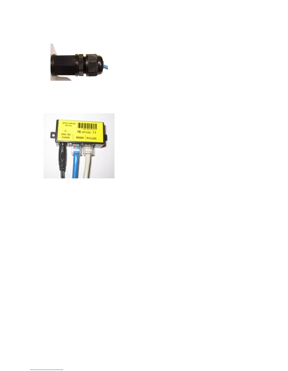
5. Screw the entire feedthru assembly into the RJ45-ECS housing which is already mounted in the
enclosure. There should be a rubber gasket between the two assemblies. Tighten the feedthru
assembly to create a seal. The final step is to tighten the compression nut until the gaskets are tight
around the Cat5 cable.
Connecting the Cables to the indoor injector:
1. Connect the antenna cable to the “radio” port
2. Connect the PC or SWITCH cable to PC/LAN
3. Connect the 18V AC/DC adapter to POWER connector
After ca 30 seconds, the radio unit will be ready for usage.
 Loading...