

Wi-Tek WI-PMS310GF-UPS User Manual

1 / 65
www.wireless-tek.com
Wi-Tek Solar UPS no-break Managed PoE
Switch Manual
Contents
一、Overview of the Switch .......................................................................................................... 2
1、WEB access' characteristics
............................................ 5
2、WEB browsing' s system requirements
................................... 5
3、WEB browsing session login
............................................ 6
4、WEB page basic composition
............................................ 7
5、Navigation tree structure
................................................ 8
6、Page button introduction
................................................ 8
7、Error message
........................................................ 9
8、Entry field
............................................................. 9
9、State field
............................................................ 10
二、WEB PAGE INTRODUCTION ............................................................................................ 11
1、Login dialog box
...................................................... 11
2、Main page
........................................................... 11
3、System Configuration
................................................. 12
4、Port configuration
..................................................... 20
5、MAC Bind
........................................................... 27
6、MAC filter
............................................................ 29
7、VLAN configuration
................................................... 30
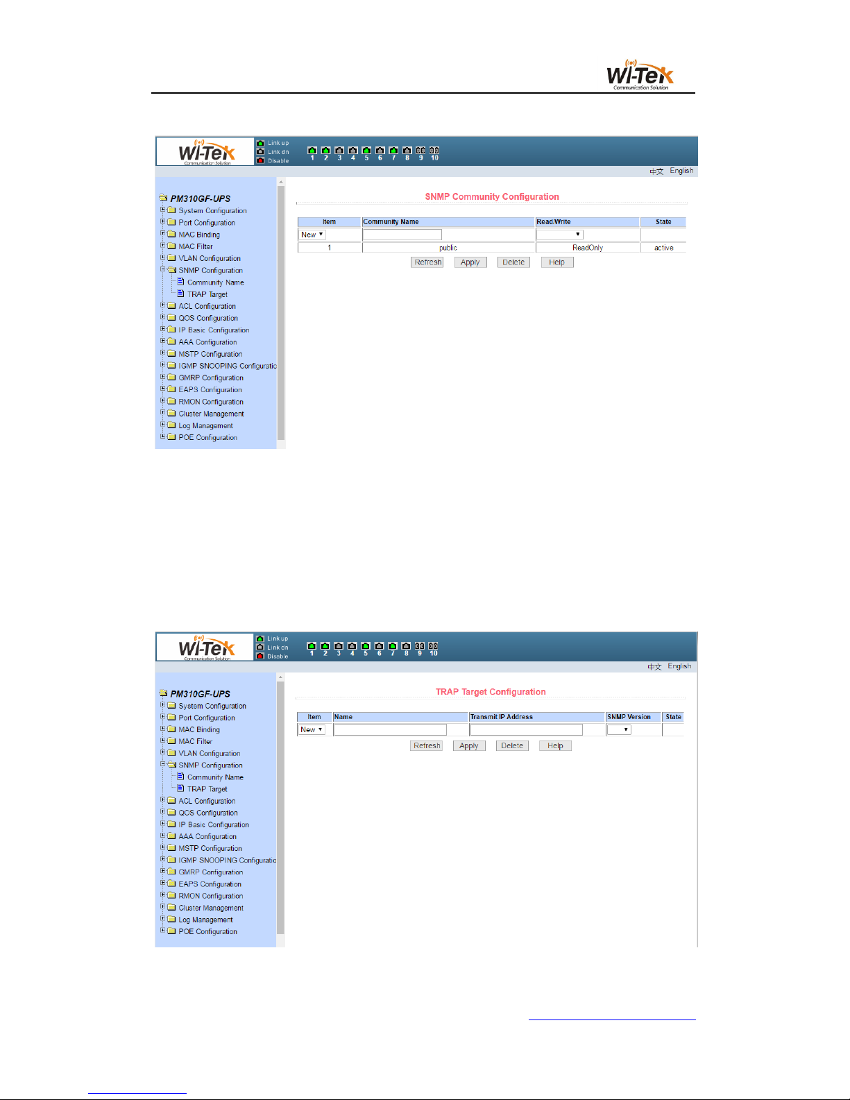
8、SNMP configuration
................................................... 33
9、Qos configuration
..................................................... 35
10、ACL configuration
.................................................... 37
11、IP basic configuration
................................................. 43
12、AAA configuration
................................................... 46
13、MSTP configuration
.................................................. 51
14、IGMPSNOOPING configuration
........................................ 53
15、GMRP configuration
................................................. 54
16、EAPS configuration
.................................................. 56
17、RMON configuration
................................................. 57
18、Cluster configuration
................................................. 60
19、ERPSc configuration
................................................. 62
20、Log management
.................................................... 63
21、POE port configuration
............................................... 64

2 / 65
www.wireless-tek.com
Wi-Tek Solar UPS no-break Managed PoE Switch Manual
This manual mainly describes the use manual page of the WI-PMS310GF-UPS
8GE+2SFP Ports 24V L2 Managed UPS No-Break PoE Switch. The user can manage the
switch through the WEB page of the switch.This manual only for each WEB page of the
operation had a simple introduction.Please refer to the User Operation Manual for each
function of the switch.
一、Overview of the Switch
Wi-Tek 8 gigabit L2 managed switch WI-PMS310GF-UPS provides 8
10/100/1000Mbps ports. The switch provides high performance, enterprise-level QoS,
advanced security strategies and rich layer 2 management features. Moreover, the
switch also comes equipped with 2 gigabit SFP slots, expanding your network flexibly.
WI-PMS310GF-UPS UPS system is designed specifically for 24VDC POE equipment
like that from Ubiquiti, WI-TEK, Mikrotik, etc. The system provides up to 150W of
continuous total PoE power on 8 switched PoE ports. Its inside battery controller
maintains the proper charge on the batteries to prevent over charge and controls the
load to prevent over discharge. With 2PCS 12V 30-80AH battery, can offer 5-24hours
back-up time. Also WI-PMS310GF-UPS ‘s inside solar controller and solar input
port(support 24V/36V Solar Panel directly) support utilize the solar capacity to extend
the backup time(and can charge battery at same time).
Highlights
8GE+2SFP Full Gigabit Switch with 8 PoE
Internal power adapter supply 150W for 8 channel 24V PoE

3 / 65
www.wireless-tek.com
support solar panel and battery for 24-hours back-up time
Inside solar controller and battery controller for charge and dis-charge battery
circulatory from solar Panel and AC
Restart AP via PoE managed page remotely
Up to 4K QVLANs simultaneously
Link Aggregation Control Protocol (LACP)
Operating Temperature -30C to +70C
WEB/CLI managed modes, SNMP, bring abundant management features

4 / 65
www.wireless-tek.com
HARDWARE FEATURES
Interface
8 10/100/1000Mbps RJ45
Ports
(Auto Negotiation/Auto
MDI/MDIX)
2 1000Mbps SFP Slots
1 Console Port
Network
Media
10BASE-T: UTP category 3, 4,
5 cable (maximum 100m)
100BASE-TX/1000Base-T:
UTP category 5, 5e, 6 or above
cable (maximum 100m)
1000BASE-X: MMF, SMF
1000Base-L X:62.5μm/50μm
MM(2m~550m) or 10μm
SMF(2m~5000m)
Fan Quantity
Fanless
Power
Consumption
150W (max. with PoE device
connected)
Power
Supply
AC 110~250V 50/60HZ
Solar
Controller
Input
24-30V 250W Up
Battery Input
24V 30AH~100AH
PoE Ports
(RJ45)
24V Passive PoE compliant
PoE Ports: Port1- Port8
Power Supply: 150W
Exchange
20G

5 / 65
www.wireless-tek.com
HARDWARE FEATURES
Capacity
Packet
Forwarding
Rate
14.9Mpps
Mac Address
Table
16K
Packet Buffer
Memory
4Mb
Jumbo
Frame
10240 Bytes
Dimensions
Product Size:
225mm* 105mm*32mm
(L*W*H)
1、WEB access' characteristics
The switch provides the features of Web access for users.Users can access the switch
through the Web browser and manage and configure the switch.The main characteristics of
WEB access :
Easy to access: Users can easily access the switch from anywhere on the network.
Users can use the familiar Netscape Communicator and Microsoft Internet Explorer
and other browsers to access the WEB page of the switch.WEB page is presented to
the user in graphical and tabular form.
The switch provides a rich WEB page,users can configure and manage most of the
functions of the switch through these WEB pages.
WEB page function’s classification and integration, user-friendly to find the relevant
page for configuration and management.
2、WEB browsing' s system requirements
Web browsing' s system requirements shown in Table 1.
Table 1:
6 / 65
www.wireless-tek.com
Hardware
and
Software
System Requirement
CPU
Pentium 586 above
RAM
128MB above
Resolution
800x600 above
Color
256 colors above
Browser
IE4.0 above or Netscape4.01 above
Operating
System
Microsoft® ,Windows95®,Windows98®,WindowsNT®,
Windows2000®,WindowsXP®,WindowsME®, WindowsVista®,
Windows7®, Windows8®,MAC, Linux,Unix operating system
Note:
Microsoft®,Windows95®,Windows98®,WindowsNT®,Windows2000®,WindowsXP
®,Windows ME®, WindowsVista®, Windows7®, Windows8® are registered trademarks of
Microsoft Corporation, all other product names, trademarks, registered trademarks and service
marks, Copyright is held by their respective owners.
3、WEB browsing session login
Before you start a Web browsing session, you need to confirm:
IP has been configured on the switch. By default, the interface IP address of the
switch’s VLAN1 is 192.168.0.1.
The subnet mask is 255.255.255.0.
A host computer with a Web browser installed has been connected to the network,
and the host computer can PING through the switch.
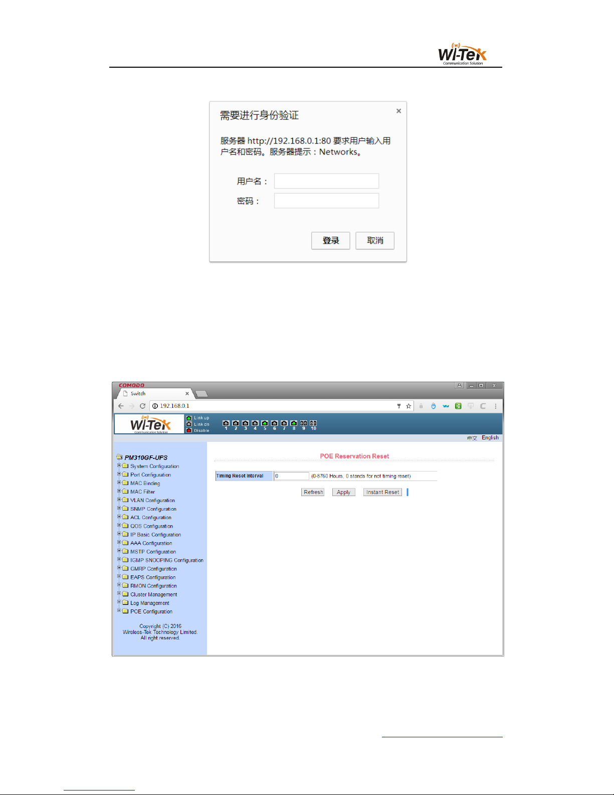
After the completion of the above two tasks, the user in the browser's address bar
enter the address of the switch and press Enter to enter the switch Web login page,as
shown in Figure 1,When multi-user management is not enabled, the user login to the
Web when the need for anonymous user (admin) password verification,Only enter the
correct password to access the Web, anonymous user password default to admin.
If the system is enabled for multi-user management and configured privileged users, the
anonymous user password will not take effect, the user access to the Web does not do
anonymous user password verification, but do multi-user management user name and
password authentication.
7 / 65
www.wireless-tek.com
Pic 1 WEB login page for browsing session
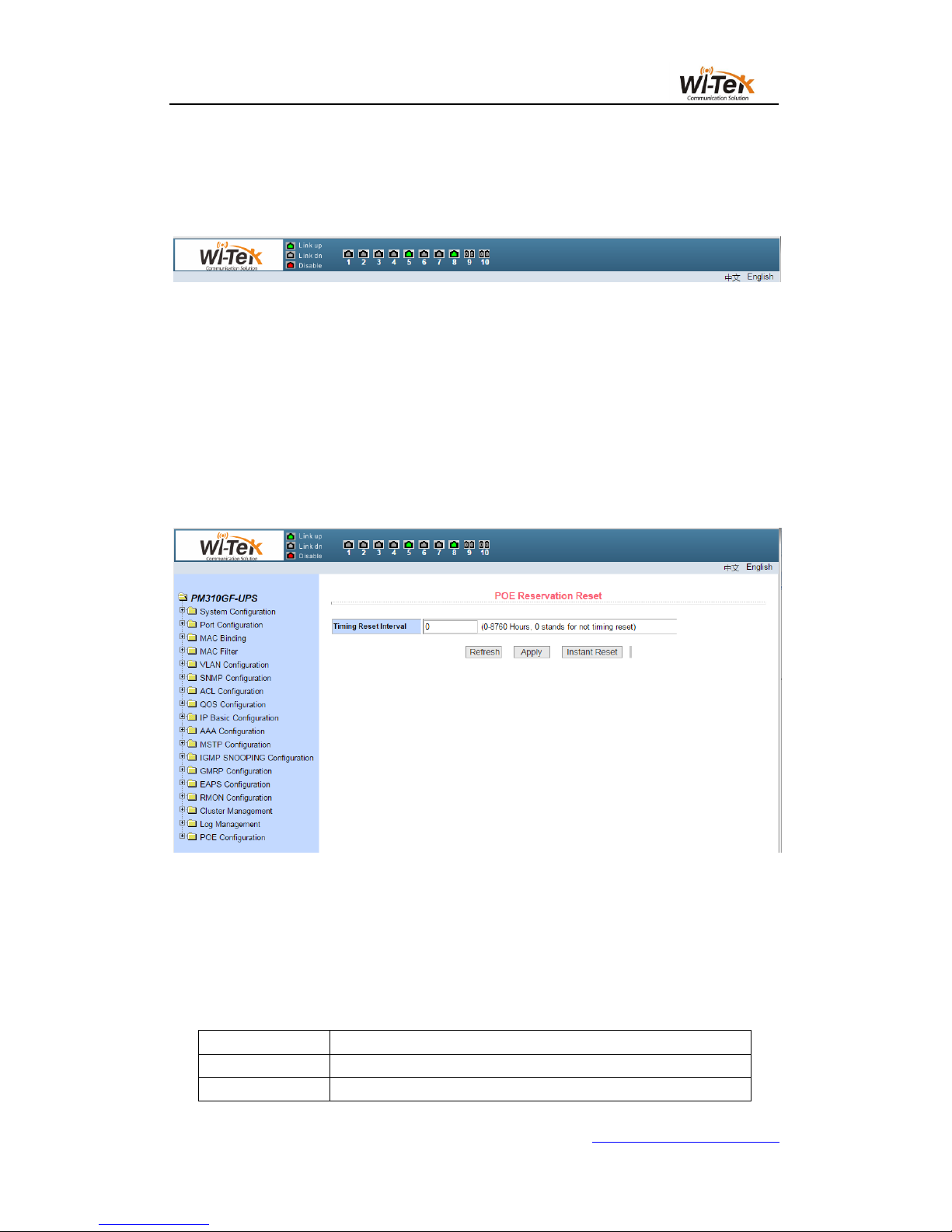
4、WEB page basic composition
Figure 2,The WEB page consists of three parts: the title page, the navigation tree page,
and the main page.
Pic 2 Switch Web page basic composition page
8 / 65
www.wireless-tek.com
Title Page Used to display the logo, and real-time port status as shown below
The green light indicates that the port is connected;
The gray light indicates that the port is not connected;
The red light indicates that the port is off ( the specific setting is shown in Figure 17 )
Main page Used to display the page selected by the user from the navigation tree.
5、Navigation tree structure
Figure 3 shows the organization of the navigation tree.
The navigation tree is located at the bottom left of each page, displaying the nodes of the
Web page in a tree, and the user can easily find the WEB page to be managed.According to
the different functions of the page will be divided into different groups, each group includes one
or more pages.Most web pages in the navigation tree are abbreviations of the page title at the
top of the corresponding page.
Pic 3 Switch the navigation tree's organization page
6、Page button introduction
There are some general buttons on the page, the role of these buttons is generally the
same, Table 2 on the role of these buttons to introduce.
Table 2:
Button
Effect
Refresh
Update all fields on the page
Application
Put the updated values in memory.Because the error check is
9 / 65
www.wireless-tek.com
done by the Web server, there is no error check before the
user selects the button
Delete
Delete the current record
Help
Open the help page and view the configuration instructions for
each page
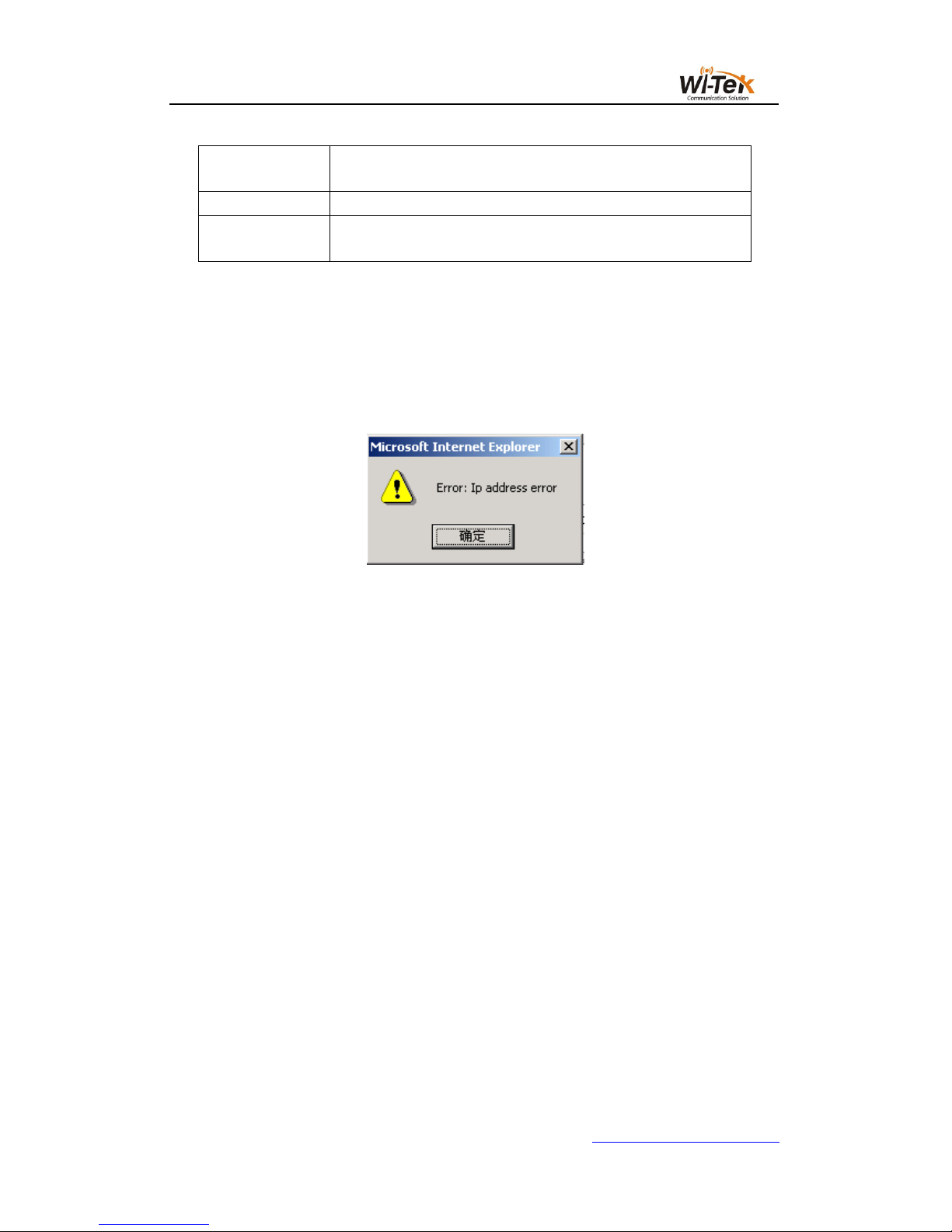
7、Error message
If the switch's WEB server is in error when processing user requests, the corresponding
error message is displayed in a dialog box.For example, Figure 4 shows an error message
dialog box.
Pic 4 Error message's page
8、Entry field
There are some pages in the leftmost column of the table that have an entry field, as
shown in Figure 5, through which you can access different rows in the table.When you select a
value in the entry field, the corresponding information for that row is displayed on the first row,
and only the row can be edited, which is also called the active row.When the first page is
loaded, the entry field displays new, the active row is empty.
If you want to add a new row, select new from the drop-down menu of the entry field, enter
the new row information, and press the Apply key.
If you want to edit an existing row, select the appropriate row number from the drop field
menu of the entry field, edit the row as needed, and press the Apply key. You will see the
corresponding change displayed in the table.
If you want to delete a row, select the corresponding row number from the drop-down
menu in the entry field and press the Delete key. The row will disappear from the table.
10 / 65
www.wireless-tek.com
Pic 5 Entry field's page
9、State field
There are some pages in the rightmost column of the table that have a status field, as
shown in Figure 6, where the field shows the row state.Since all row state changes are
processed internally, the status field is read-only.Once all the domain information in the row is
valid, the row state becomes automatically active.
Pic 6 State field's page
11 / 65
www.wireless-tek.com
二、WEB PAGE INTRODUCTION
The WEB pages of the switch are organized into groups, each consisting of one or more
Web pages. The following is an introduction to each page.
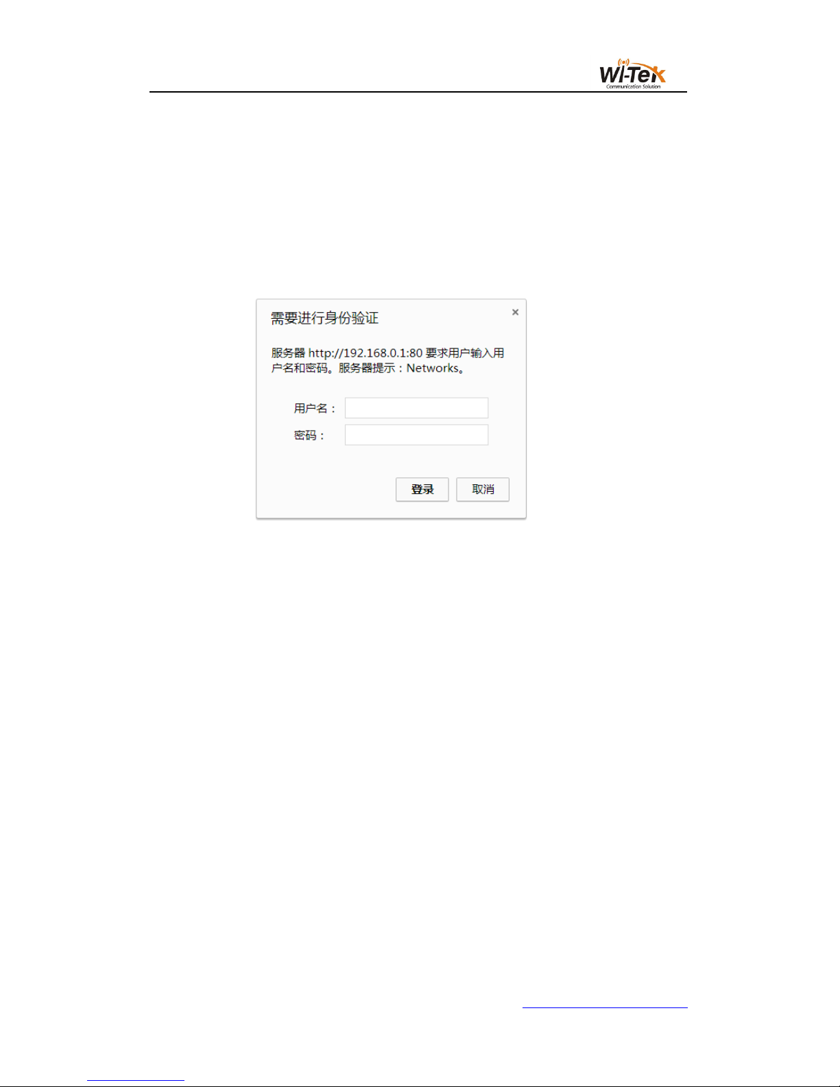
1、Login dialog box
Pic 7 WEB Browse the session's login page
Figure 7 shows the login dialog box, which is displayed when the user first logs in to the
web page.The user enters the user name and password in the corresponding field, and then
clicks the OK key to log in to the Web server of the switch.Password is case-sensitive,
anonymous user password can be set up to 16 characters, and multi-user name and password
are up to 16 characters can be set.
The default user name for the switch is anonymous user name admin. The default password
is anonymous user password. Anonymous user password is empty by default.
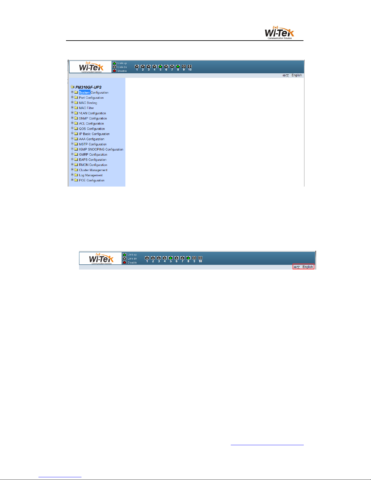
2、Main page
Figure 8 shows the WEB main page of the switch. The page will be displayed after the
user logs in to the page.
12 / 65
www.wireless-tek.com
Pic 8 Switch the main page
3、System Configuration
Language switching: switch buttons in the upper right corner and easily switch between
Chinese and English system interfaces.
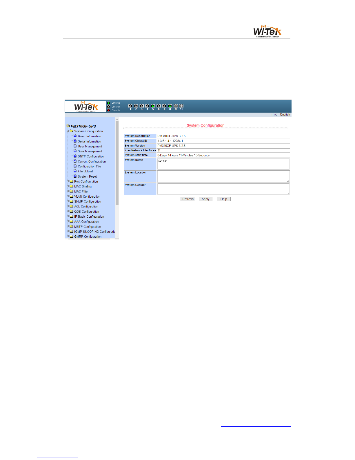
(1)Basic information page
Figure 9 shows the basic information configuration page where the user can configure the
basic information for the switch.
System Description Displays a description of the system-related parameters.
The system descriptor identification number indicates the identity of the system in network
management.
The system version number shows the version number of the current software used by
the switch.
The number of network interfaces displays the current number of network interfaces in the
switch.
System Startup Time Displays the time the switch was started to the present time.
The system clock displays the current clock of the system. The user can modify the
system's current clock and need to enter the year, month, day, hour, minute, and seconds
parameters.
The system name displays the system name of the switch in the network. The user can
modify the system name.
13 / 65
www.wireless-tek.com
The system location displays the physical location of the switch in the network, and the
user can modify the system location.
System contact display management of the current node contacts and contact information,
the user can modify the system contact.
Pic 9 Basic information page
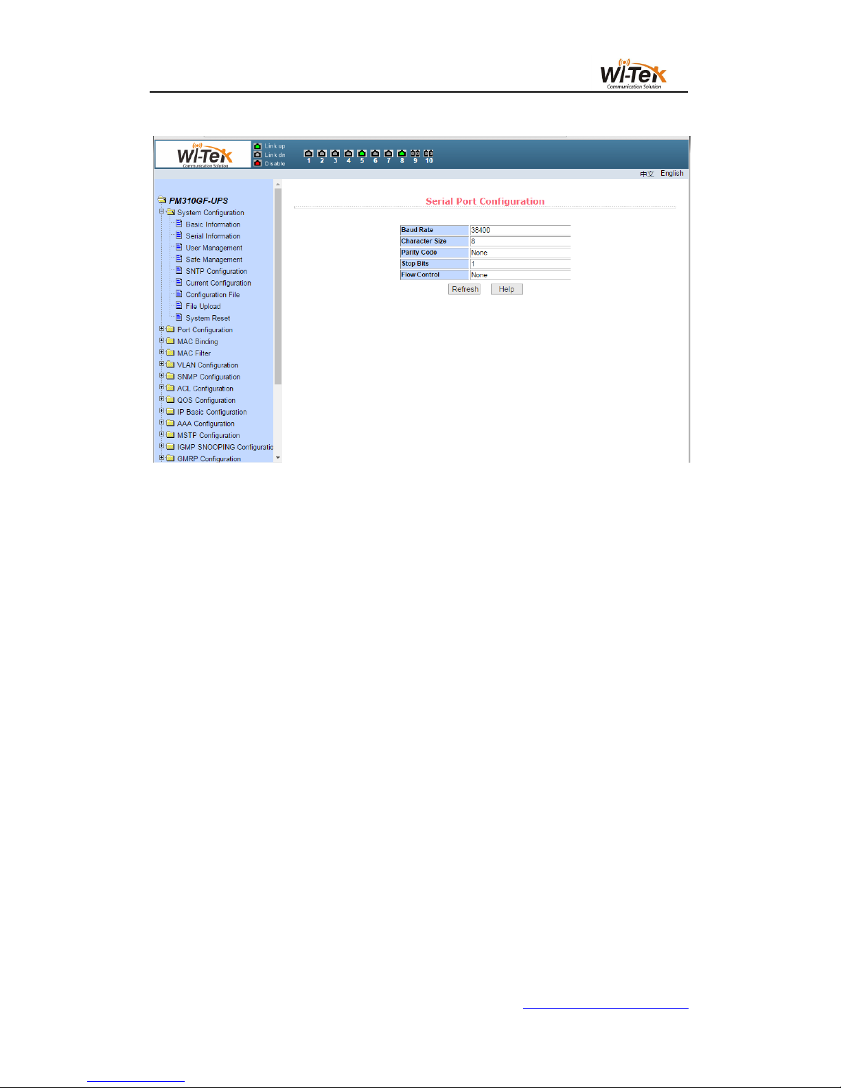
(2)Serial port configuration page
Figure 10 shows the serial port configuration page, which shows the serial port baud rate
and other information related to the serial port.When the host through the serial terminal (such
as Windows HyperTerminal) to manage the switch, the serial port terminal COM port
configuration must be consistent with the information on this page.
14 / 65
www.wireless-tek.com
Pic 10 Serial port configuration page
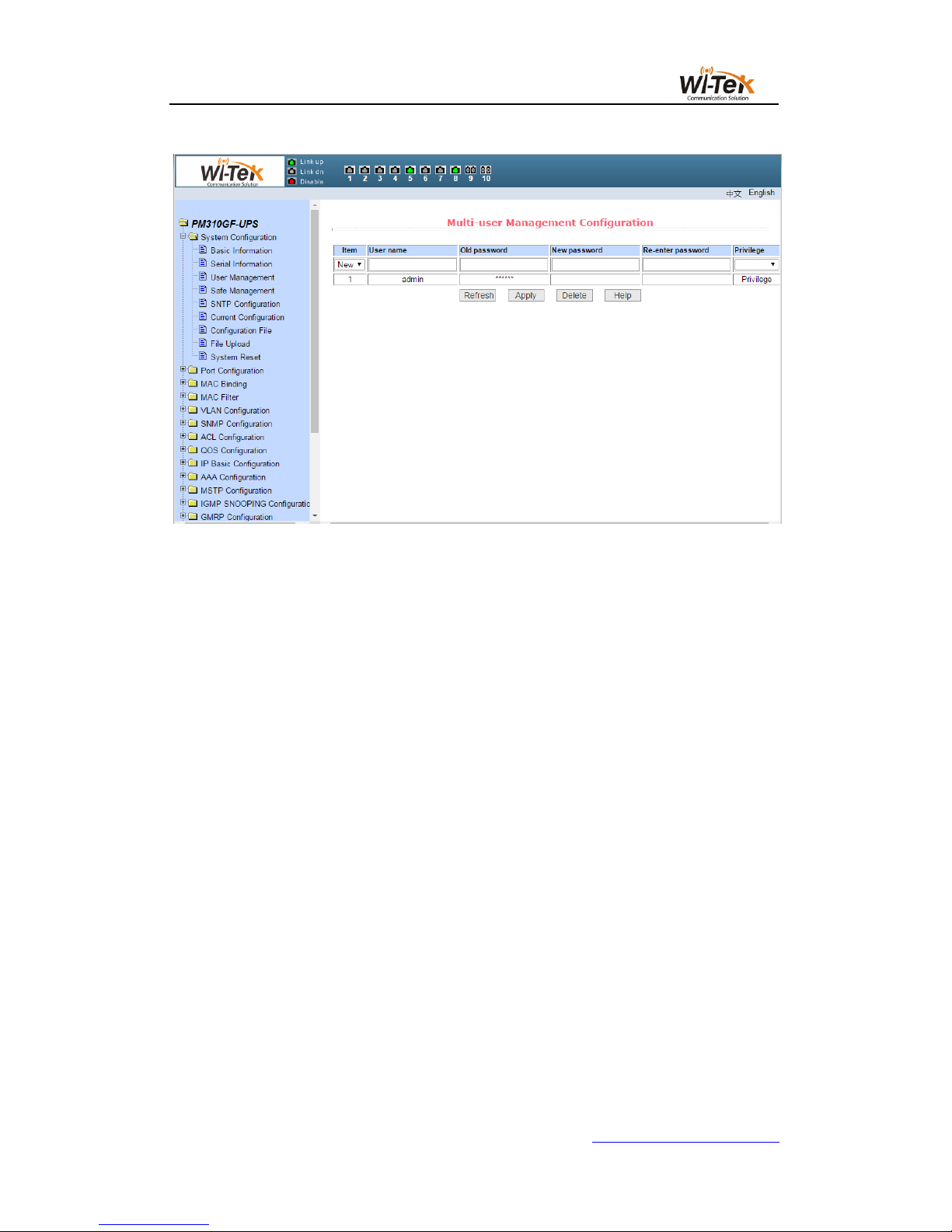
(3)Multi-user management configuration page
Figure 11 shows the Multi-user management configuration page, through this page users
can modify the switch's anonymous user (admin) password.Telnet and Web use the same
anonymous user password when multiple users are not enabled.Passwords are case sensitive
and you can set up to 16 characters at most.If you want to change the password, the user
needs to enter the new password twice, once the user clicks the application key, the new
password is activated,If the switch does not enable multi-user, will display the login dialog box
(shown in Figure 7), the user needs to re-login page, the user must enter a new anonymous
user password login WEB page.
At the same time through this page users can configure multiple users, the switch default
no multi-user, that is the default does not enable multi-user management functions, then login
does not require multi-user user name and password authentication.For Telnet, when adding a
user name, the multi-user management function is enabled, and when all the users are deleted,
the multi-user management function is turned off again.For the Web, when a user name is
added, if be the privileged user,the multi-user management function is enabled, when all the
privileged users are deleted, the multi-user management function is closed again.When the
multi-user management function is enabled, the anonymous user password will not take effect,
login Telnet and Web need to multi-user user name and password authentication.When the
multi-user management function is closed, at this time if the anonymous user password is
configured, login Telnet and Web need to anonymous user password verification.
15 / 65
www.wireless-tek.com
Pic 11 Multi-user management configuration page
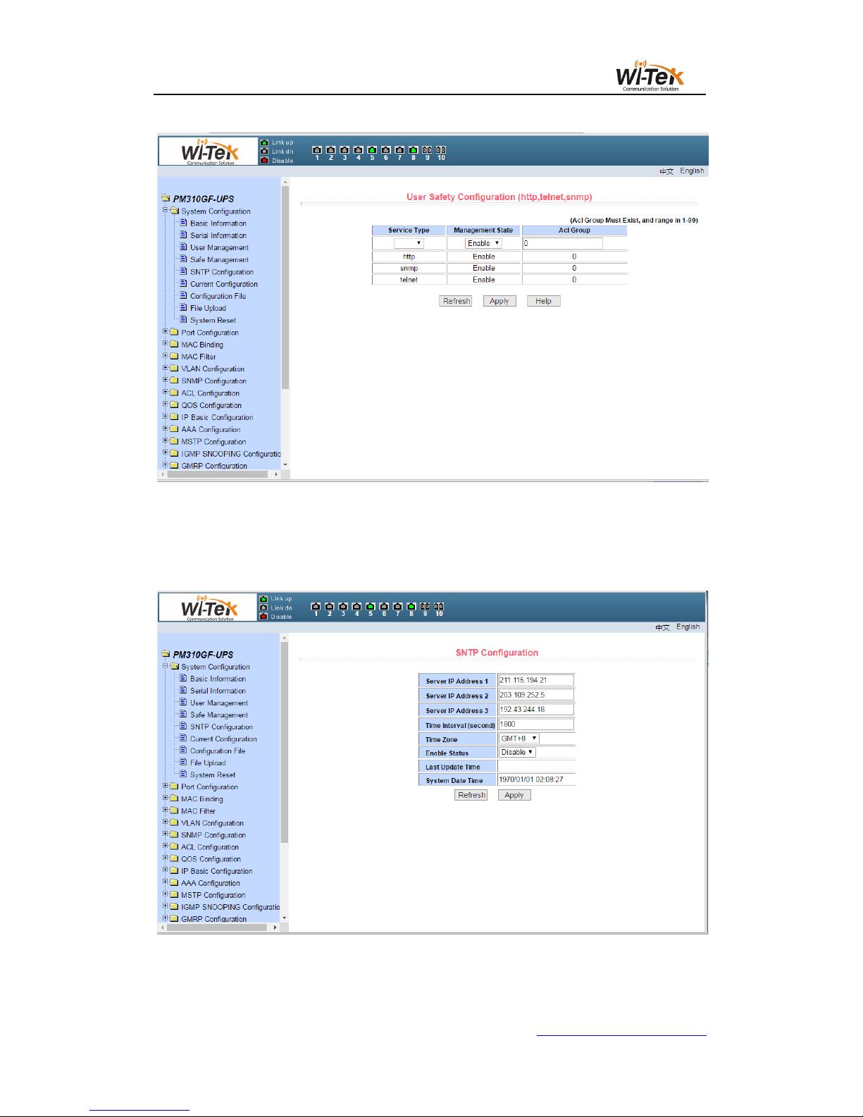
(4)User safety configuration page
Figure 12 shows the user safety configuration page, through the configuration of the page,
the administrator can control the network management services TELNET, WEB and SNMP
control, you can open or close these services,These services can be linked with the IP
standard ACL group, the implementation of source IP address control, control the host access
to these services.
Switch by default TELNET, WEB and SNMP services are open, and do not do ACL
filtering, that is, all the hosts can access the switch of these three services.If the administrator
for security, do not want to provide other users one or several of these services, can shut down
one or more of these services.Administrators only want a specific host to access one or more
of these services, can one or several of these services do ACL filtering.When a service needs
to do ACL filtering, you need to open the service and select an IP standard ACL group (1-99).
The ACL group must exist.
It should be noted that if the administrator on this page to control the WEB service (such
as the closure of WEB services) may make users can no longer use the WEB page,At this time
through other ways to log on the switch and control WEB services so that users can use the
WEB page (such as open the WEB service).
16 / 65
www.wireless-tek.com
Pic 12 User safety configuration page
(5)SNTP configuration page
Figure 13 shows the SNTP configuration page, where the administrator can configure and
view the system clock through configuration of the page.
Pic 13 SNTP configuration page
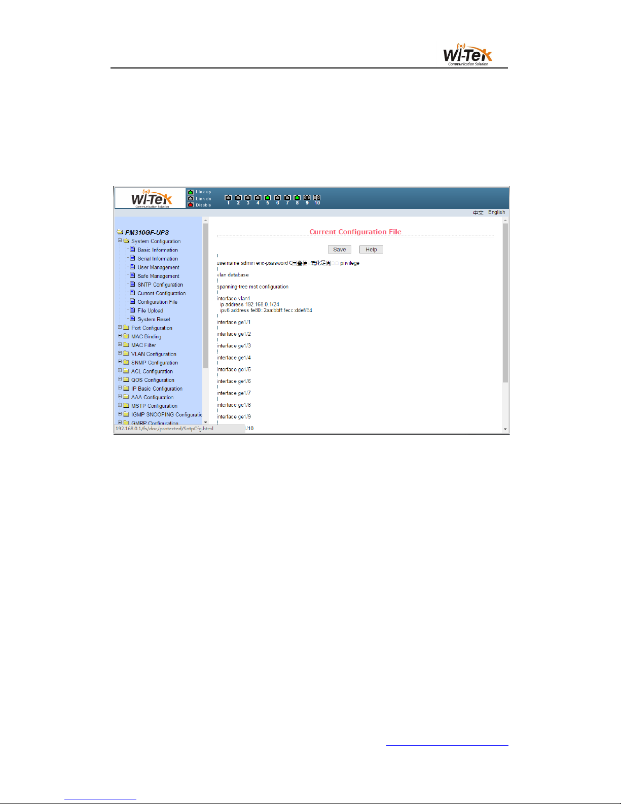
(6)Current configuration file page
17 / 65
www.wireless-tek.com
Figure 14 shows the current configuration file page.Through this page, the user can view
the current configuration of the switch.The save key stores the current configuration of the
system into the configuration file.Because the storage operation needs to erase the FLASH
chip, which takes a certain amount of time.When the user is configured on the page and want
the configuration is not lost after restart the switch , you must click the Save button before exit
the page in the current configuration page.
Pic 14 Current configuration file page
(7)Configuration file page
Figure 15 shows Configuration file page.This page allows the user to view the initial
configuration of the system.The initial configuration is actually the configuration file in the
FLASH,When there is no configuration file in FLASH, the system is started with the default
configuration.Delete key to delete the configuration file in FLASH.Click the delete button, will
pop up a dialog box, the dialog box prompts the user whether to determine the deletion of the
configuration file, if determined by the dialog box on the OK button, otherwise press the Cancel
button.The download key is used to download the configuration file to the PC.Click the
download button, will pop up a dialog box, the user chooses to save the directory path and
save the configuration file. The file name of the downloaded configuration file is switch.cfg.

18 / 65
www.wireless-tek.com
Pic 15 Configuration file page
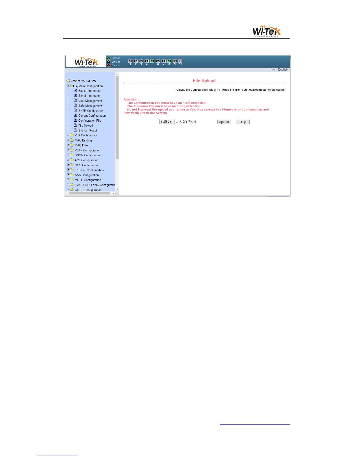
(8)File upload page
Figure 16 shows the file upload page, through which users can upload configuration files
and image files to the switch.Click the Browse button to select the directory path of the
uploaded profile or image file on the PC.Click the upload key to upload the configuration file or
image file. The configuration file suffix must be * .cfg. The image file must be provided by the
manufacturer and the file name suffix must be * .img. Do not click on other pages or reboot the
switch before the transfer results page returns. Otherwise, the file transfer failure causes the
system to crash.
19 / 65
www.wireless-tek.com
Pic 16 File upload page
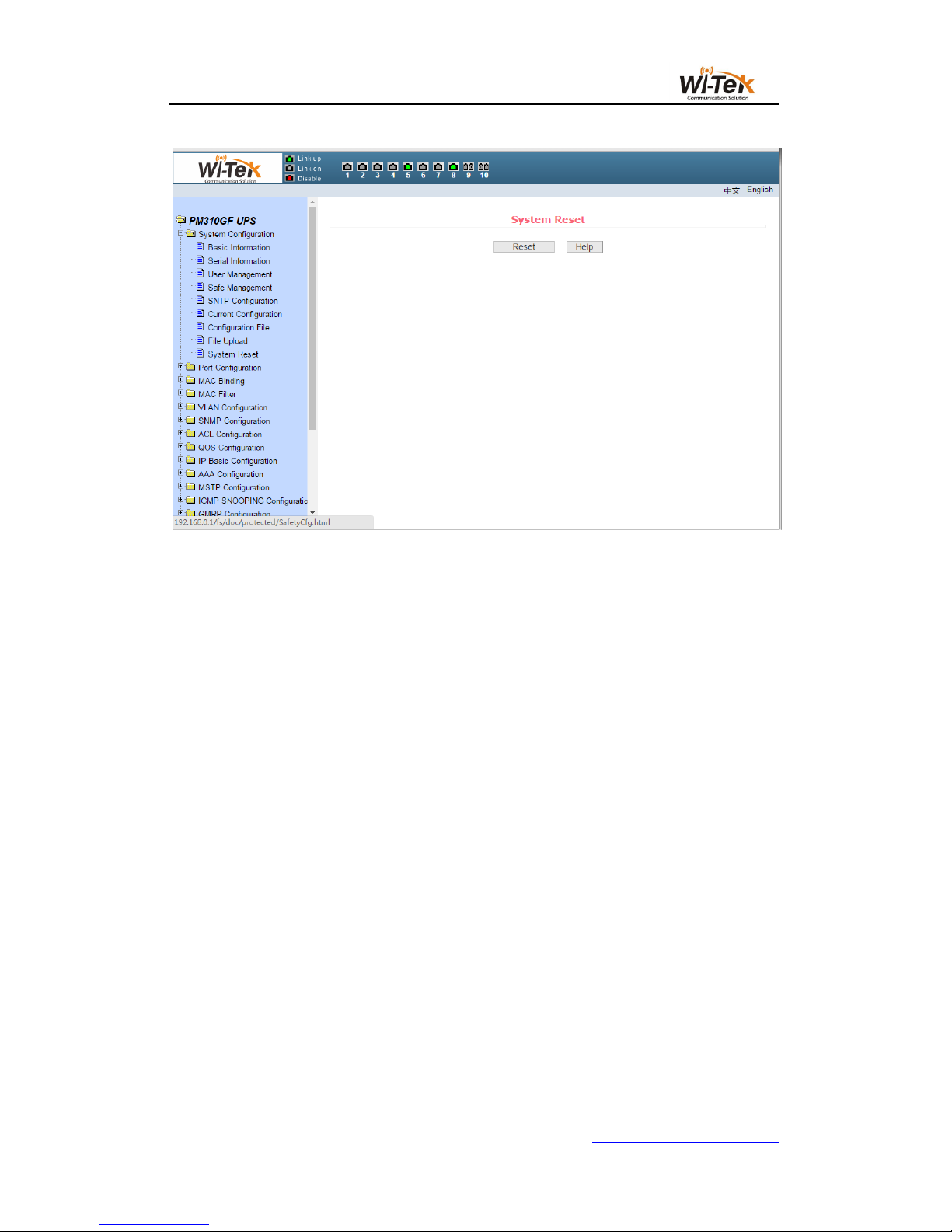
(9)System reset page
Figure 17 shows the system reset page, through this page users to restart the
switch.When you click the restart button, a dialog box will pop up prompting you if the user is
sure to restart the switch. If OK, press the OK key. Otherwise, press the Cancel key.The Web
page will no longer be opened when it is restarted.
20 / 65
www.wireless-tek.com
Pic 17 System reset page
4、Port configuration
(1)Port configuration/show page
Figure 18 shows the port configuration/show page.The user can enable or disable the port
through this page, set the port speed, or view the basic information of all ports.
To set a specific port, select the appropriate port name in the drop-down menu for the
user's port.Port status defaults to up, and you can select the down in the drop-down menu to
disable the port.The user can also choose to set the speed drop-down menu to set the speed
of the port, such as the mandatory semi-duplex for the port, 10M (half - 10), etc. Users can
view other basic information for all ports from this page.
 Loading...