

Wi-Tek WI-AC150 User Manual

1
WI-AC150
AC Controller User Manual

2
Content:
This manual is subject to guide users on how to use this Network Gateway and WLAN
Controller properly, suit for those familiar with basic networking knowledge and
terminology,
It including the product main features such as packing content, hardware introduce and
AC Controller, Routing, Firewall, Management,VLAN Setting and VPN Setting. It is
highly recommended to learn this manual before starting the configuration.
Chapter 1: Product Instruction, Default Data, Packing....................................................3
Chapter 2: Hardware Introduce....................................................................................... 4
Chapter 3: Login..............................................................................................................4
Chapter 4: WEB GUI Configuration.................................................................................5
4.1 AC................................................................................................................6
4.1.1 Device List.......................................................................................6
4.1.2 Server Config...................................................--.............................7
4.1.3 Zero Config......................................................................................8
4.1.4 Device Group.................................................................................10
4.1.5 Device Log.....................................................................................11
4.2 LAN............................................................................................................11
4.2.1 LAN ...............................................................................................12
4.2.2 Static DHCP...................................................................................13
4.3 WAN...........................................................................................................13
4.3.1 WAN Setting...................................................................................13
4.3.2 Load Balance..................................................................................15
4.3.3 Policy Routing.................................................................................15
Chapter 5 Behavior.........................................................................................................18
Chapter 6 Flow Control...................................................................................................18
Chapter 7 Security Center..............................................................................................19
7.1 Port Mapping.....................................................................................19
7.2 URL Filter..........................................................................................20
7.3 IP Filter..............................................................................................20
7.4 MAC Filter..........................................................................................21
7.5 DMZ...................................................................................................21
Chapter 8 IP/Time Group................................................................................................22
Chapter 9 Authentication.................................................................................................22
Chapter 10 Routing.........................................................................................................27
Chapter 11 Device..........................................................................................................28
11.1 Management...................................................................................28
11.2. Device Log.....................................................................................29

3
11.3. Firmware Upgrade.........................................................................29
11.4 Modify Password............................................................................29
11.5 Maintenance.................................................................................30
11.6 Reboot Device................................................................................30
11.7 System time....................................................................................31
Chapter 12: Cloud..........................................................................................................32
Chapter 13: DDNS.........................................................................................................32

4
Chapter 1: Product Instruction, Default Data, Packing
Gateway & WLAN Controller
Power Cable
Setting Accessory
User Manual
Warranty Card
1.1 Product Instruction:
WI-AC150 is an SMB Gateway and WLAN Controller, With main function of Router, AC
Controller, Management, VLAN Management functions;
Work as a router, it can access into 500 end users, to do advertisement and captive portal
authentication。
Work as a controller, it can manage 150PCS FIT wireless access points produced by
The working diagram showed as follow:
1.2 Default Data:
Management IP address & LAN IP address: 192.168.10.1
Login Password: admin
WAN 1 IP address: Dynamic IP Access
1.3 Packing and Accessory
Chapter 2: Hardware Introduce
Hardware:
WAN1: WAN Port in Default
WAN2/LAN5; WAN3/LAN4; WAN4/LAN3: LAN Ports in default, but can set up as WAN
ports in gateway operation mode based on needs.
LAN1, LAN 2: LAN Ports in default
CONSOLE: serial port
Power: When power on, power LED indicator will be on;
RUN: When this device run in good status, this LED indicator will be flashing
Chapter 3: Login
3.1: Setup an IP address for PC, The IP address should be anyone between
192.168.10.2~192.168.10.254;
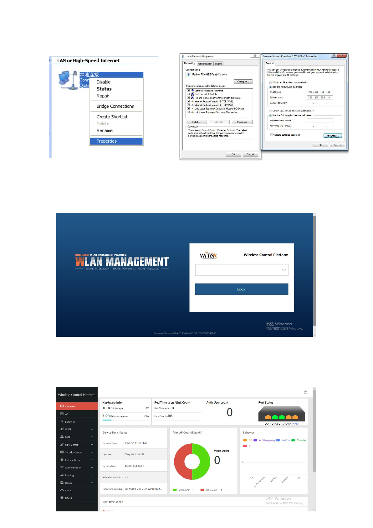
5
3.2 Open IE browser, input AC Controller’s IP address 192.168.10.1, Enter to log in AC
controller’s WEB GUI.
3.3 Input login password, the default password is admin, then click on Login button.
Chapter 4: WEB GUI Configuration
When login this AC controller, the following home page will pop up as follow:
6
Hardware Info: Mean the CPU, Memory usage status
RealTime Users: Mean the QTY of end users access into it when it work as Gateway.
Link Count: Mean the QTY of internet link.
Auth User count: The QTY of authentication users.
Network Port Status: Show the WAN/LAN Ports
connect status; Green mean connected; Yellow mean not connected
Device Basic Status: The status of system time, uptime, MAC address, firmware version.
Max AP Count: QTY of wireless AP connected, MAX is 200, Online AP show working AP,
Offline AP mean not working AP; WLAN Users: User QTY connected to wireless AP
Behavior: Mean users behavior, for example, user use QQ, Ali Wangwang, WeChat...
Real time speed: Mean the WAN Ethernet speed, different WAN with different color
Uptime: Mean AC controller running time
: Log out the WLAN Controller
Let’s introduce AC, LAN, WAN, Behavior, Flow Control and other function one by one to
make users with more understanding in this product.
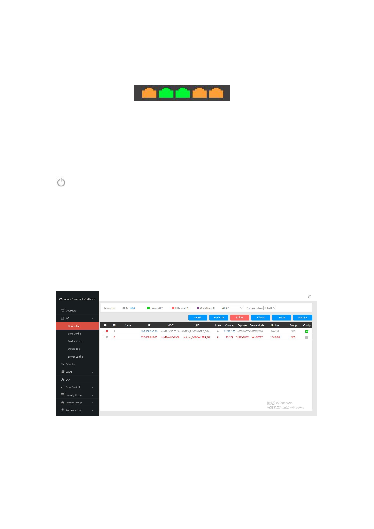
4. 1. AC
AC: Wireless AP control and management
Click button of AC, it will pop up following picture, which showed all the wireless AP
connected into this WLAN controller.
4.1.1 Device List
Device List to show the online/offline wireless AP list.
All AP: Show QTY of wireless AP which connected with this WLAN controller
Offline AP: Show QTY of wireless AP which offline already
Online AP: Show QTY of wireless AP which online
WLAN Users: Show QTY of end users which access into wireless AP.
Search: Search the wireless AP by IP address or MAC address
7
Batch Set: Set Channel, TX Power, Time to restart, Max users, device login password in
batch.
Delete: Delete the choosed wireless AP from this device list.
Reboot: Restart this wireless AP
Reset: return to factory default
Upgrade: Upgrade firmware.
: if tick it, mean select all the wireless AP; If tick here, mean select this
wireless AP;
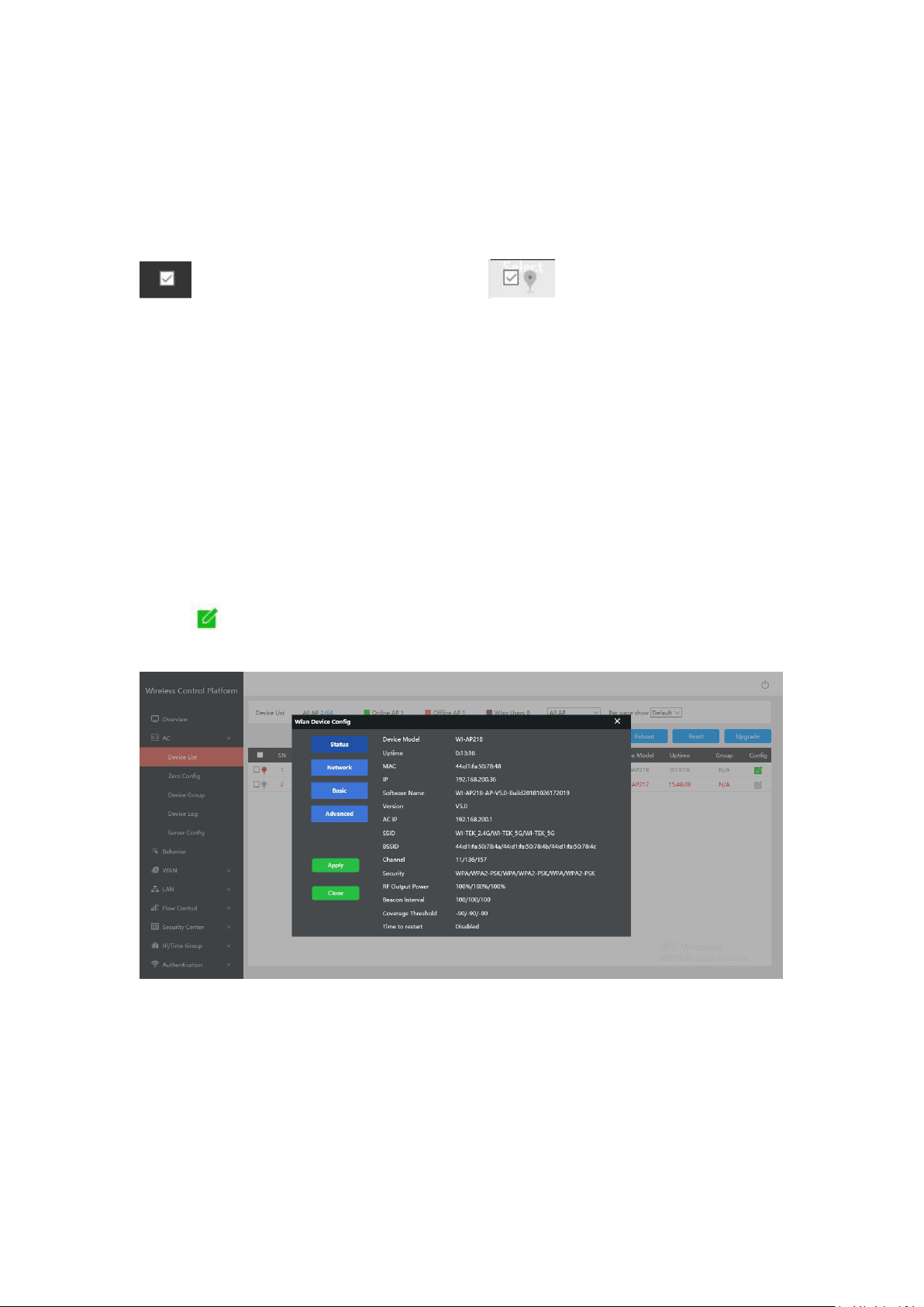
Name: Can mark AP the location or model number other information which easy to know
this wireless AP.
IP: The wireless AP’s IP address
MAC: MAC address of wireless AP
SSID: Show the SSID of device 1 and device 2
Users: Mean how many users connected with this wireless AP
Channel: Show this wireless AP’s channel, including device 1 and device 2
TxPower: Mean the wireless AP’s RF power
Device Model: Model number of this wireless AP
Uptime: running time
Group: Show group name directly, N/A mean no group for this wireless AP;
Config : to check the wireless AP’s working status, configure the wireless AP’s basic
and advanced data.
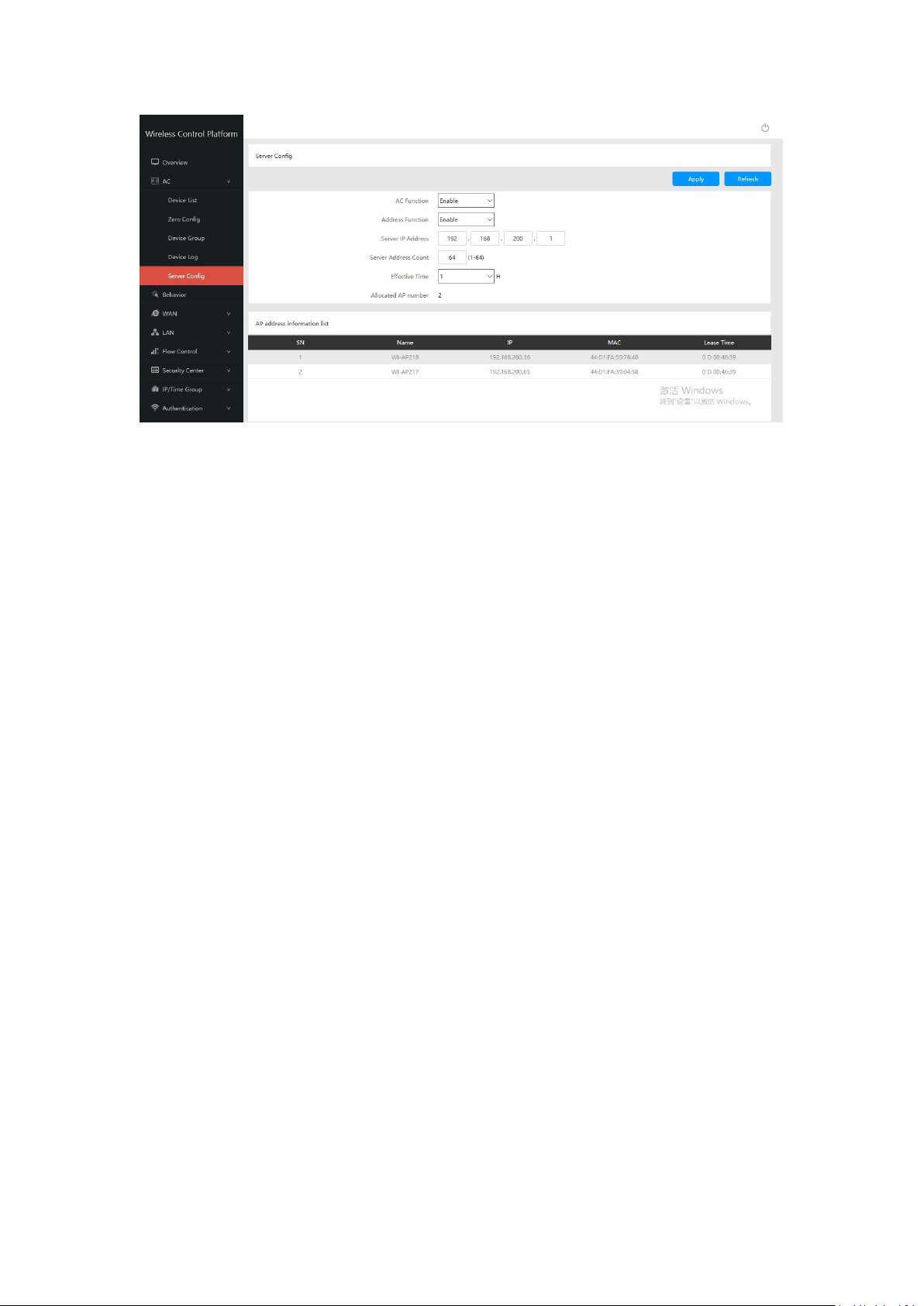
4.1.2: Server Config:
Server: Mean this AC controller can assign IP address for wireless AP automatic, no need
to change wireless AP’s IP address one by one
8
Refresh: to refresh the wireless AP’s IP address
1. If configure this function after wireless AP connected into this network, then all wireless
2. There is one group only in Zero config, which will make all wireless AP in same SSID,
Function: Enable/Disable, default is Enable
Server IP address: default is 192.168.200.1; can change to anyone you like, but pls note,
if server IP is 192.168.200.1, then wireless AP’s IP address will be one from
192.168.200.2 to 192.168.200.254, to 192.168.201.X, to 192.168.202.X... if server
address count is 1500.
Server Address Count: default is 1500, can be 1~1500, based on the QTY of wireless
AP.
Effective Time: can be 1~24 hours
Allocated AP number: show the QTY of wireless AP which assigned IP address by this
WLAN controller.
When setup the above data, click Apply to save it.
AP address information list: to show wireless AP’s model number, IP address, MAC
address and running time.
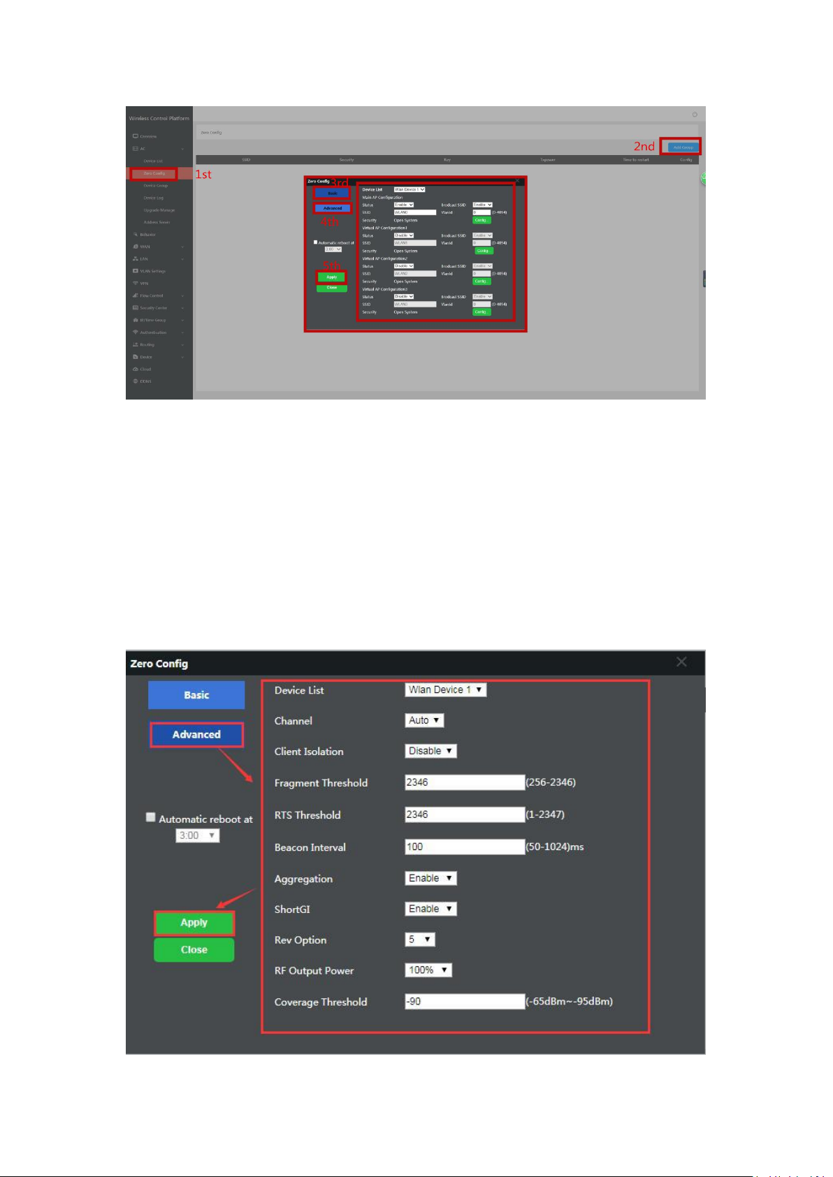
4.1.3: Zero Config
This function make wireless AP plug and play, but recommend to configure this function
before connect wireless AP into this network as following reason:
AP should be reboot, then wireless AP will get the configuration from Zero config.
password, channel..., if want to different AP in different group, recommend Device Group
function in 4.1.4.
9
Wireless Basic: to setup wireless AP’s SSID, password, Tag VLAN
Device List: Wlan Device 1 and Wlan Device 2; Wlan Device 1 mean 2.4G Radio mainly;
Wlan Device 2 mean 2.4G or 5.8G radio, based on wireless AP.
Main AP Configuration: setup the wireless AP’s main SSID, Tag VLAN, Configure
Password.
Virtual AP Configuration: setup the wireless AP’s virtual SSID, Tag VLAN, Configure
Password. The default status is disable for this virtual SSID.
Automatic Reboot at: Mean can setup this wireless AP reboot at certain time automatic,
to improve the performance.
Wireless Advanced: to set up the channel, RF power, ShortGI, Coverage Threshold of
wireless AP
10
Channel: Auto in default, but recommend to setup channel by manual based on
environment.
RF Output Power: 100%, 75%, 50%, 25%, 12.5%, can adjust it based on application.
More RF Power, mean more WiFi Range;
Coverage Threshold: This make end users to connect the outdoor CPE with stronger
signal strength;
For example, If one outdoor CPE with -80dBm coverage threshold data, another outdoor
CPE with -95dBm coverage threshold data, then end users will connect the outdoor CPE
with -95dBm coverage threshold always even this outdoor CPE with very weak signal
strength.
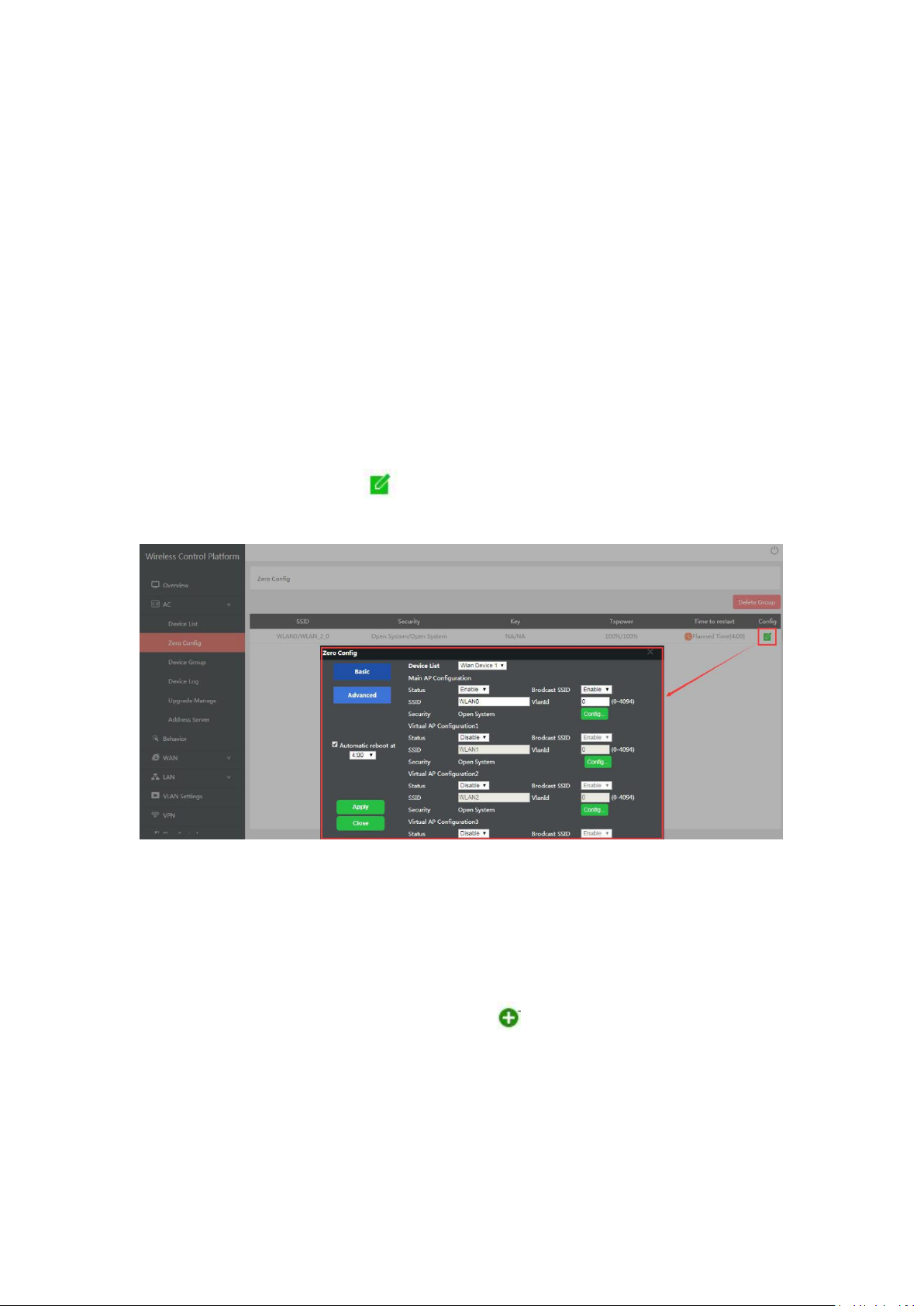
After setup all the data, click Apply to add zero config group as follow:
Please note, click config button , can modify the parameters if need.
Delete Group: If need, can delete this zero config group.
4.1.4 Device Group
In device group, can be more than one group, then different AP can be in different group.
The steps is: Add Group----Config Group----Click to Add AP into this group----Wireless
AP will get data from this group.
Please note, the configuration in device group is same as Zero Config.
Add Group
 Loading...