

Page 1

WISYCOM s.r.l. - Via Spin, 156 - I-36060 Romano d’Ezzelino (VI) - Italy - MTH300- eng-u03.doc
Tel. (Ph.). +39 0424 382605 - Fax +39 0424 382733 - http:// www.wisycom.com
- e-mail: [email protected]
MTH300 QUICK USER GUIDE
MTH300 is a professional radio microphone especially design for broadcast/high quality
applications.
1. OPERATION
MTH300 is composed by 3 detachable parts:
1) MIC Head (available with cardioid/hypercardiod polar pattern).
2) MIC Body (the below part can be open to access “Display & Setup controls” area
(fig.1) and on the back the “Batteries holder & Infrared” area (fig. 2).
3) MIC Antenna, made with fibreglass reinforced housing and with a “Wireless power
switch” (fig. 3). “MIC Antenna” is fastened to body with 2 anvils and a microconnector.
1.1 LED INDICATION (POWER SWITCH)
Led indication with bicolor led (red & green) on wireless power switch (fig. 3):
- Wireless transmission status: green on/off)
- Battery status: green steady, slowly blinking (< 25%), quickly blinking (<12%)
- Modulation peek (if activated): red
- Ptt status: red if active
1.2 BATTERIES
MTH300 is working with 2 AA alkaline or NiMH batteries (select correct type on setup controls).
Battery status can be checked on internal OLED display or looking to LED status on power
switch (see 1.1)
1.2.1 BATTERY SUBSTITUTION
Open MIC body: unscrew counter-clockwise the below cover to access batteries holder;
Take out below battery to release upper battery leverage;
2
nd
battery falls down and can be removed.
Wireless power switch
with programmable
LED indication
(green/red).
Open MIC Body:
Unscrew & slide down cover, to
acces internal setup controls and
batteries holder & infrared.
Fig. 1 Display & Setup controls Fig. 2 Batteries holder and infrared
Fig. 3 Wireless
power switch
Exchange head:
unscrew it counter-clockwise
1
2
3
Page 2
WISYCOM s.r.l. - Via Spin, 156 - I-36060 Romano d’Ezzelino (VI) - Italy - MTH300- eng-u03.doc
Tel. (Ph.). +39 0424 382605 - Fax +39 0424 382733 - http:// www.wisycom.com
- e-mail: [email protected]
1.3 POWERING UP
Move the wireless power switch (fig. 3) in upper position (towards MIC body) to activate
wireless transmission: a green LED lights up (blinking when battery is low!).
1.4 SETUP CONTROLS
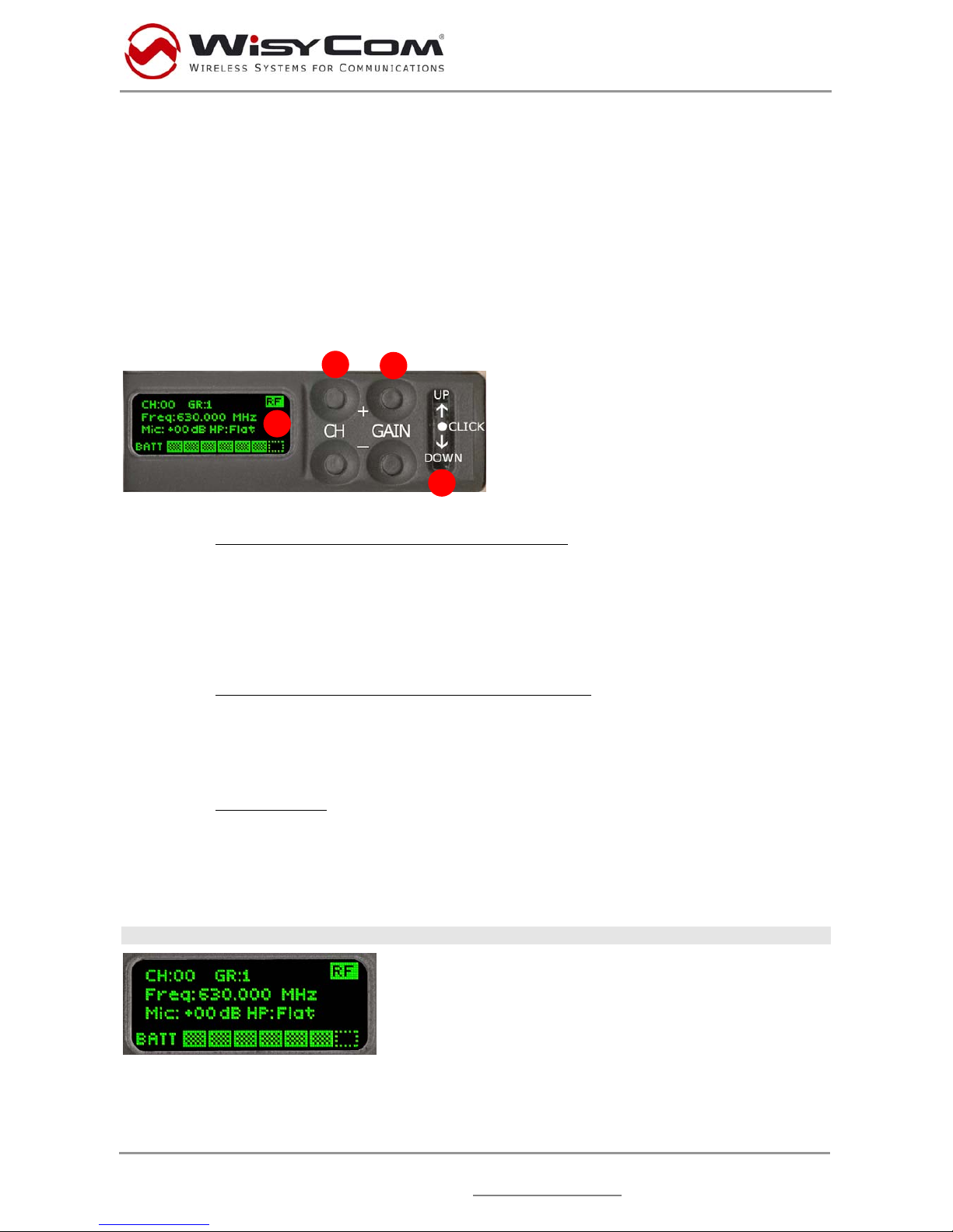
Open MIC Body to access the “display and controls” area (fig. 1):
A) Graphics Display (OLED)
B) Channel selection buttons (ch+ / ch-)
C) MIC gain setup buttons (gain+ / gain-)
D) 3 position selector (up / down / click)
Fig. 5
1.4.1 OLED POWER UP (OLED IS IN OFF CONDITION)
Pushing down selector (click), oled turns on. A first menu with serial NO and brand logo is
display, then <status> menu enters automatically.
Pushing and holding selector (click) > 2 sec, serial NO menu is displayed till up/down is
selected.
1.4.2 OLED POWER DOWN (OLED IS IN ON CONDITION)
Pushing and holding selector (click) > 2 sec, display is turned off.
Display turns off automatically after 15 sec, unless in <irda> menu or in <audio> menu (with
audio level < 5% from nominal).
1.4.3 DISPLAY MENU
Setup menu are accessed in sequence:
<status> <tuning> <audio> <rf power> <other> <irda> <Lock>
Using up/down selector all menus can be accessed in sequence.
1.4.3.1 <status> menu
This is the first menu displayed after power up.
Major info are displayed:
- Current channel/group (i.e. CH:00 GR:1)
- Current frequency (i.e. 630 MHz)
- Mic gain (i.e. +00) and high pass filter (i.e. FLAT)
- RF active, top right label RF (if present RF is on)
A
B
C
D
Page 3
WISYCOM s.r.l. - Via Spin, 156 - I-36060 Romano d’Ezzelino (VI) - Italy - MTH300- eng-u03.doc
Tel. (Ph.). +39 0424 382605 - Fax +39 0424 382733 - http:// www.wisycom.com
- e-mail: [email protected]
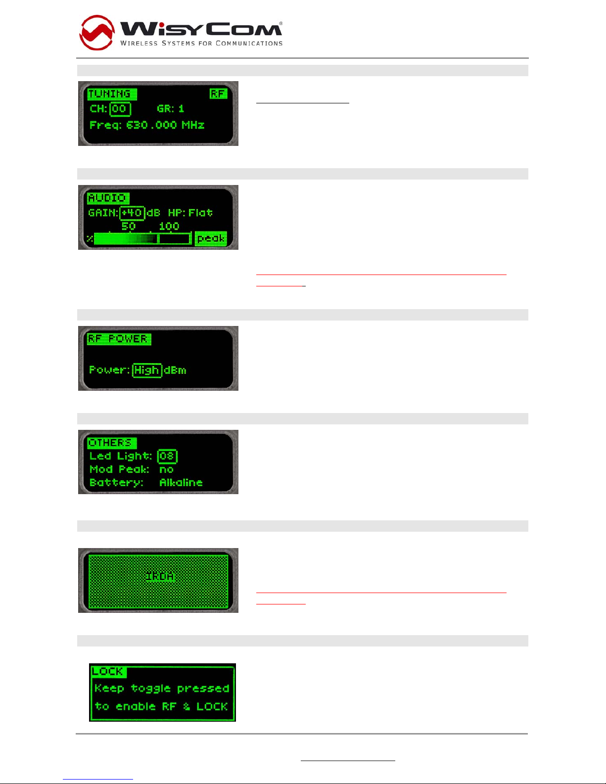
1.4.3.2 <tuning> menu
This menu can be entered by scrolling selector or using
quick channel setup
buttons (ch+ and ch-).
In this menu current channel/group and frequencies can
be setup. Sync group is a quick self settable channel
synchronized from receiver.
1.4.3.3 <audio> menu
This menu can be entered by scrolling selector or using
quick gain setup buttons (gain+ and gain-).
To help proper audio gain setting, an audio bar is
supplied (with peak hold bar) TRY TO SETUP TO
HAVE A MAX PEAK HOLD BAR CLOSE TO 100.
High pass audio filter can be setup with different preset
values.
NOTE: while in this menu display is not automatically
turned off.
1.4.3.4 <rf power> menu
This menu can be entered by scrolling selector.
RF power can be setup to High (50 mW ERP) or Low (10
mW ERP).
1.4.3.5 <others> menu
This menu can be entered by scrolling selector.
Power switch green LED brightness can be setup LED
light. Modulation peak LED on power switch (become
RED when audio get close to saturation) can be
enabled/disabled). Battery type can be setup in Alkaline
or NiMH.
1.4.3.6 <irda> menu
This menu can be entered by scrolling selector.
While is this menu MIC can be connected to IRDA for
setup or firmware upgrades.
NOTE: while in this menu display is not automatically
turned off.
1.4.3.7 <lock> menu
This menu can be entered by scrolling selector.
Long pressing (2 sec.) selector button (click) it locks
MTH300 in transmission mode.
To unlock, long pressing (2 sec.) selector button again.
Page 4
WISYCOM s.r.l. - Via Spin, 156 - I-36060 Romano d’Ezzelino (VI) - Italy - MTH300- eng-u03.doc
Tel. (Ph.). +39 0424 382605 - Fax +39 0424 382733 - http:// www.wisycom.com
- e-mail: [email protected]
 Loading...