

Page 1
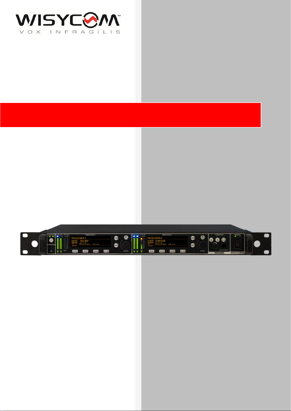
MRK980 User Manual
ULTRAWIDEBAND TRUE
DIVERSITY DUAL RECEIVER
SN: ________________
rev.01 (ref. FW 1.2)
Date: 13 February 2019
Page 2

MRK980 User Manual
rev.01
1
General Description
Wisycom MRK980 is a true diversity, ultra-wideband dual channel receiver. With its 1090MHz
of band switching, it ensures the users an exceptional band flexibility, combined with a superb
selectivity and inter-modulation immunity, for best operating performances of the wireless
microphone systems. MRK980 also features an internal DSP processor, Wisycom famous
Multicompanding system, new Dante compatibility and a completely and renewed user interface,
which make this system easy and quick to setup.
MRK980 is designed to be:
“easy & quick to use” thanks to automatic setup functions (i.e. frequencies, squelch), remote
configuration utilities (Dante/Ethernet control connections), a display with intuitive context
menu navigation and shortcut buttons on the front panel.
“extremely flexible”, with an incredible frequency agility of 1090MHz (VHF/UHF/DME); more
than one rack can be connected together thru a simple ethernet cable to act as a multi-channel
receiver. Moreover the DSP board allows the units to work with several digital audio outputs
(i.e. AES/EBU, DANTE, …), with multi-companding compatibilities and the new adaptive
squelch function.
“best in class performances”, thanks to the latest Wisycom technology the unit has extreme
RF sensitivity and immunity plus a superb audio quality.
“a durable & upgradable investment”, thanks to the very robust design (aluminum housing)
and the possibility of upgrade/enhance units performances with simple slot in card (pc-like
thru the DEXB expansion bus)
Moreover MRK980 system is already set up for the exclusive PTT function (remote command),
developed and patented by Wisycom:
Simply pushing this button (PTT), the presenter causes the remote switching of the
receiver’s output-line, from the “main line” to the additional “intercom line”, in order to
be able to talk “off-air” directly with the technical team. Then all PTT’s MICs can be
connected in pre-fading allowing a clever intercom setup.
Page 3

MRK980 User Manual
rev.01
2
AFETY INSTRUCTION
S
Read this safety instruction and the manual first.
Follow all instructions and information.
Do not lose this manual.
Do not use this apparatus under the rain or near the water.
ATTENTION: supply the apparatus with a correct mains voltage and with the ground
connection. Check the power cord integrity.
The power cord must be protected from damage.
Do not install the apparatus near heaters or in hot environments, do not use outside the
operating temperature range.
Mount the apparatus as indicated in the instruction, do not block side grids for air
ventilation.
If the external air filter is mounted, clean it regularly.
WARNING: do not open the apparatus, RISK OF ELECTRIC SHOCK!
Do not open the apparatus, only qualified service technician are enabled to operate on it.
The apparatus needs servicing when is not properly working or is damaged by liquids,
moisture or other objects are fallen in the apparatus.
Use only accessories or replacement parts authorized or specified from the manufacturer.
Do not supply more than 7 apparatus MRK960 from the mains output, see power
requirements for other apparatus.
Clean the apparatus only with dry cloths, do not use liquids.
The ON/OFF is a double pole circuit breaker, but to ensure the complete disconnection of
the apparatus, disconnect the power cord.
Report the serial number and the purchasing date in front of the manual, it is needed to
have proper replacement parts or accessories from the manufacturer.
When replacement parts are needed, use only replacement parts authorized from the
manufacturer. Substitution with not authorized parts could result in electric shock,
hazards or fire.
o
Keep attention on all the labels with warnings or hazards on the apparatus.
WARNING: The apparatus is intended for professional use; anyway the manufacturer
alerts the user that the headphone output power of the apparatus could exceed the level
of 85 dB(A) of sound pressure level and this could be dangerous for the hearings. Do not
use the headphone with high power level or for long time. Reduce the power or suspend
the hearing in the case of any kind of hearing problem.
Page 4

MRK980 User Manual
rev.01
3
AIN FEATURES
M
Two channels true diversity receiver (full DSP processing)
Up to 1090 MHz bandwidth in 170/1260 MHz range
Push to talk (PTT) enabled with dedicated outputs (optional)
Analogue, AES/EBU & Dante outputs (with redundancy
Dante machine Synchronized mode no sample rate delay!
Next Gen Multiband front-end filtering:
High Q moving filter in 170-230 MHz
High Q moving filter in 470-800 MHz
High Q moving filter in 960-1160 MHz (DME) (or 806-810 MHz saw filter –
Japan)
Country specific saw filters:
USA 940-960 MHz or Japan 1240-1260 MHz
Wideband and Narrowband DSP-FM operation (SW selectable):
o Narrowband allows 50% more band efficiency (200/250 kHz channel density)
o Narrowband allows about 3dB extra sensitivity and noise immunity
Extreme low noise VCO with ultrafast spectrum scan for optimal quick & easy setup
High contrast OLED display
Monitor & control through USB and Wisycom Manager 2.0 (computer SW)
Expansion slot for GPIO or future additional features
Page 5
MRK980 User Manual
rev.01
4
ECHNICAL DESCRIPTION
T
The MRK980 is a professional dual diversity receiver for wireless microphones reception especially
designed for broadcast production, live stages, theatres and top professional applications.
IMRK980 key features are:
High immunity on strong Rf environment
Incredible switching bandwidth
Top class audio performances and flexibility thanks to the digital processors
High reliability and durability
One of the milestones in the design of the MRK980 is high reliability as most of the circuitry of the
receiver is completely independent one from each other.
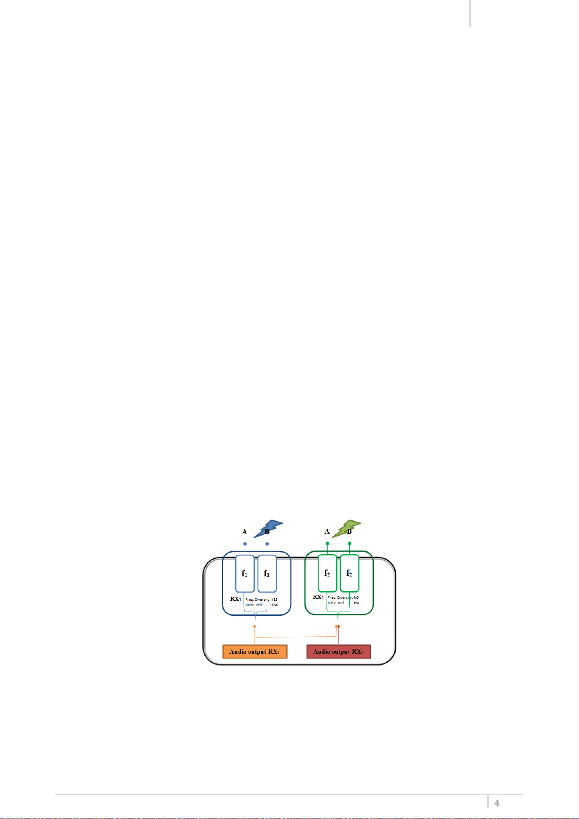
Below you can see the schematic with an overview of main receiver functions.
Starting from the antenna inputs, each antenna could be independently powered from a single
power regulator monitored from the microcontroller.
For each antenna the RF signal is split in the receiver 1 and in the receiver 2 (antenna A and antenna
B) with a wide band splitter. This way any of the two receivers could be tuned into any frequency of
the switching range, e.g. you can have receiver 1 in VHF and receiver 2 in DME band.
Receiver 1 and 2 are true diversity receivers: each one is made of two receivers tuned on the same
frequency, hereafter called section A and section B. The receiver 1 section A and the receiver 2
section A are connected to the antenna A, the receiver 1 section B and the receiver 2 section B are
connected at the antenna B.
Each receiver has its own demodulated signal and its own RSSI signal (Receiver Signal Strength
Indication); a microcontroller select or combine signals from section A & B to have the best audio.
The demodulated signal flows to the digital audio processor.
Page 6

MRK980 User Manual
rev.01
5
The data sub carrier is digitally filtered to a very selective equivalent filter (bandwidth 3Hz). Each
filter has its own data demodulator, one for medium speed data detection at the output of the first
filter and one at low speed data detection at the output of the second filter. All the two
demodulators are connected to the supervisor micro controller for the data battery detection and
signaling.
Digital audio processor (one for each receiver): the demodulated signal is filtered by an anti aliasing
low pass filter and then converted into the digital domain with a 96KHz/24bit audio A/D converter.
The digital signal processor (DSP), working in double precision, replicates all the analog functions
with very high accuracy, ultra-low distortion and without the typical analog problems as
components tolerances or temperature drifts etc. The high speed audio algorithms maintains the
audio delay at about 0.37 milliseconds, making it ideally for live events and to keep audio delay as
short as possible. The DSP unit also filters and demodulates the data carrier and communicates all
the parameters and information to the supervisor micro controller. The audio output goes to the
digital outputs (AES3) or is converted in the analog domain with a high quality 24 bits 96KHz D/A
converter and an anti-aliasing filter.
The analogue audio signal is routed in three parallel ways, LINE, COM and HEADPHONE MONITOR
amplifier.
The HEADPHONE MONITOR amplifier is controlled by the buttons on the front panel and by the
volume knob. The monitor output depends on the squelch and on the tone squelch only in the TSQ
ON selection. In TSQ OFF and in TSQ ADV the monitor output is muted only by the squelch control.
The two analogue audio ways, LINE and COM, has the same audio quality and are controlled by the
“Tone squelch matrix”. Each audio driver has a VCA for the soft switching of the audio signal and
the muting functions, controlled by the supervisor microcontroller. After the VCA, an electronically
balanced amplifier drives the output signal, directly or thru a very low impedance screened audio
transformer (optional). The audio output without transformer could withstand up to +52 Vdc of
phantom supply with no damage and up to 100V with transformer.
Page 7
MRK980 User Manual
rev.01
6
USER GUIDE
FRON PANEL
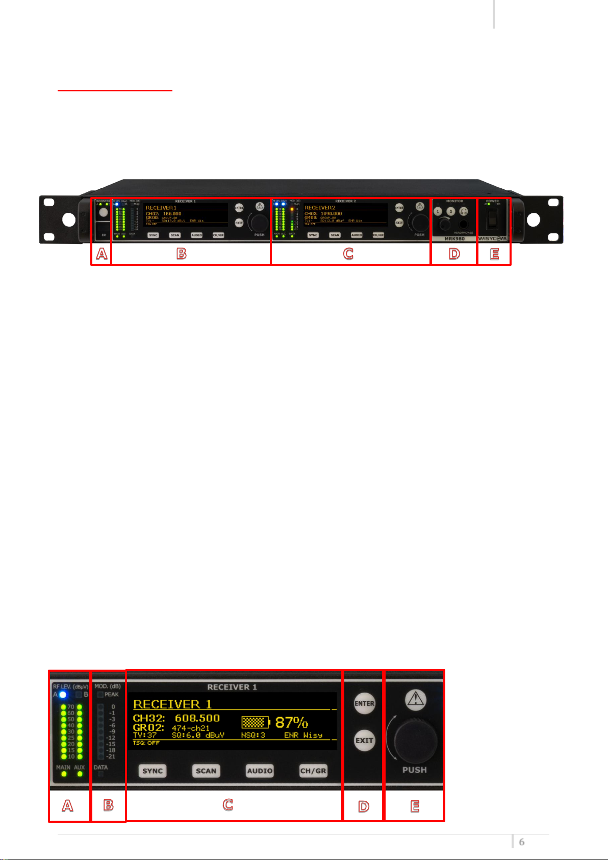
MRK980 allows an easy and quick configuration using buttons, push knobs and displays.
The front panel is functionally divided in the following section:
A – ANTENNA BOOSTER and INFRARED PORT: ON/OFF booster button for A&B antennas and
IRDA port.
B – RECEIVER 1 CONFIGURATION: display, menu and shortcut buttons
C – RECEIVER 2 CONFIGURATION: display, menu and shortcut buttons.
D – MONITORING AREA: monitoring audio output on headphone jack (6.3mm - ¼”)
RECIVER POWER SWITCH: turn the receiver ON/OFF.NOTE: the devices takes 5 secs
E –
to turn OFF for safety reasons (e.g. accidental turn OFF)
RECEIVER 1 and RECEIVER 2
Page 8
MRK980 User Manual
rev.01
7
4 5 6
7
1 2 3
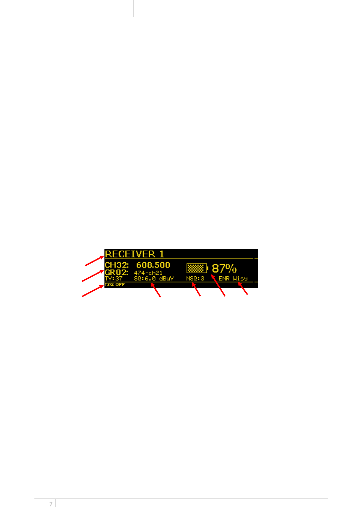
AREA A: Rf Bars, MAIN and AUX led indicates what output port is currently in use.
AREA B: Modulation bar and DATA led which indicates the Ethernet connection status
(ON/OFF)
AREA C: Receiver display (Name, channel info, audio info, sub menu) and shortcuts buttons
(SYNC, SCAN, AUDIO, CH/GR) to quickly access the main receiver functions.
AREA D: action button to choose or exit while inside the menu.
AREA E: rotary knob to scroll inside the menu and choose different option (push) and light
indicator.
- Fixed Yellow (Warning): no audio on both COM and AUX outputs
- Red slow blinking (Alarm level 1): Tx battery level <25%
- Red fast blinking (Alarm level 2): Tx battery level <12%
- Red fixed (Alarm level 3): A or B antenna short circuit (pop up on
the display will also shows up “Overcurrent on antenna A/B”)
LCD DISPLAY: MAIN VIEW
All the basic information on the receiver status can be found on the main menu overview.
Here you can find the following info:
1. Receiver name
2. Current tuning frequency, Group, Channel and TV Channel
3. Tone Squelch Status (ON/OFF)
4. Squelch Level
5. Noise Squelch Level
6. Transmitter Battery Life status
7. Compander currently in use
Thru the main menu on the LCD display and the LED bars for the RF level and modulation the user
has the complete monitoring in real time of the wireless channel in use.
Page 9
MRK980 User Manual
rev.01
8
REAR PANEL
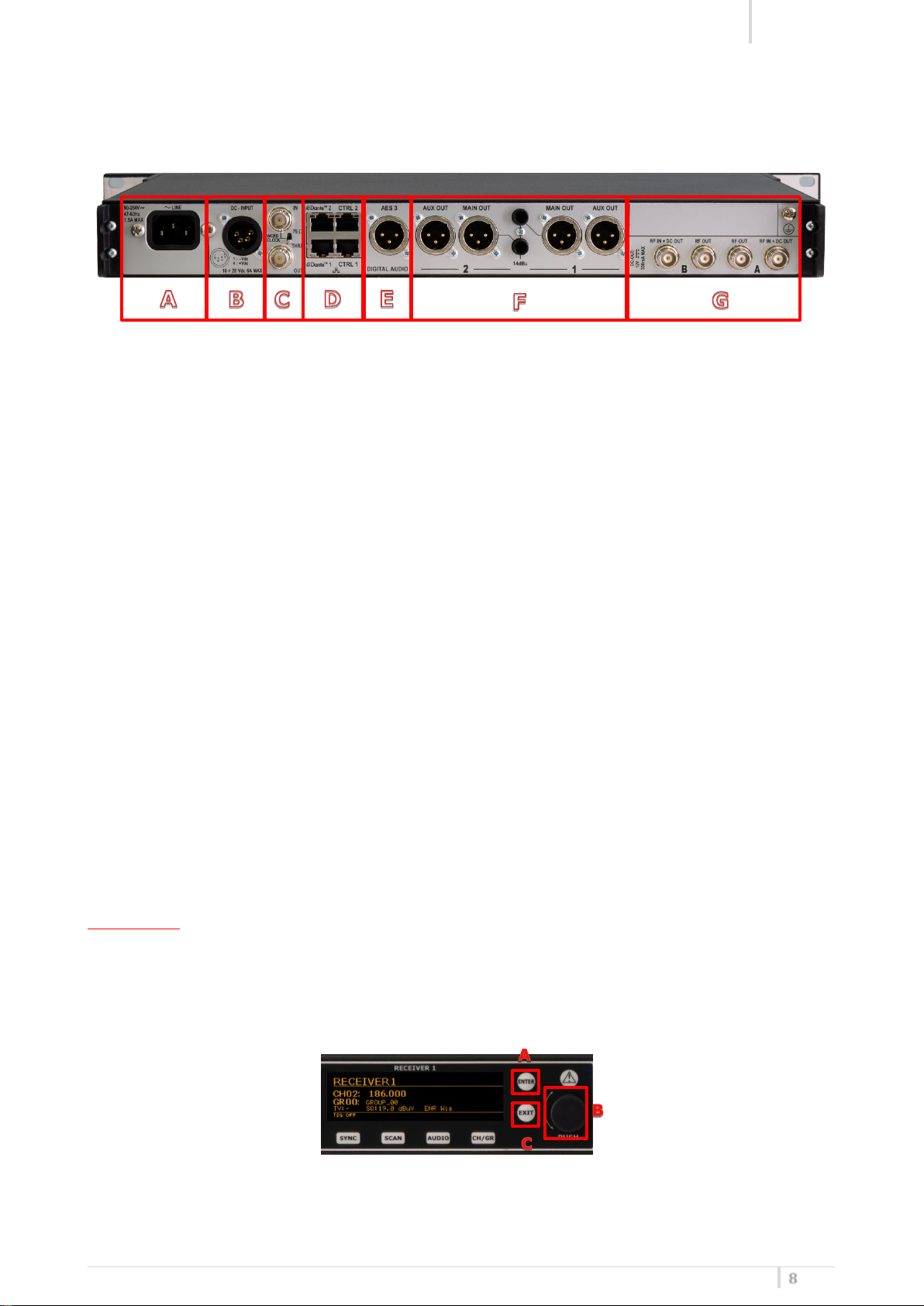
The rear panel is functionally divided into the following sections:
A – Main Power Supply
B – Redundant +12V DC Power Supply
C – Word Clock I/O
D – Remote control module: redundant Dante connectors and redundant Ethernet connectors
E – AES3 Digital output
F – Receiver 1 and Receiver 2 Audio outputs: Main, Aux and TRS
G – Antenna BNC I/O
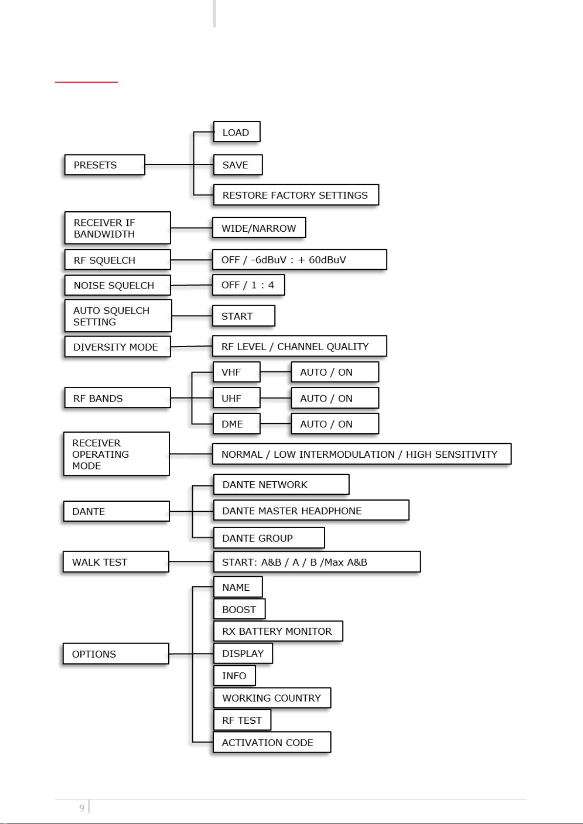
TREE MENU
To access the receiver main menu and the sub menus press the “ENTER” button (A) or rotary knob
(B).
Use the “EXIT” button to exit the sub menus.
Keep pressed “ENTER” or the rotary knob to confirm your selection. Scroll into the menu by
using the rotary knob.
Page 10
MRK980 User Manual
rev.01
9
MAIN MENU
Page 11

MRK980 User Manual
rev.01
10
Via Spin 156 I-36060 Romano d’Ezzelino Italy
Tel. +39 -0424 -382605 Fax +39 - 0424 - 382733
www.wisycom.com e-mail: [email protected]
 Loading...