

WisyCom MRK950, MRK950H, MRK950M, MRK950I, MRK950-EX User Manual
...
MRK950-MRK960
Manager
Products: MRK950 (options L,H,I,M)
MRK950-EX (options W,X) and MRK960
Rev: rev02 (ref. Wisycom Manager 2010 v1.1.4.6)
Date: 23 July 2014
rev02
MRK950-MRK960 Manager
Pag. 1
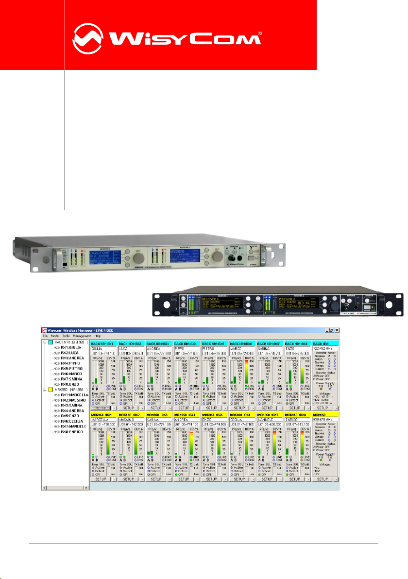
WISYCOM WIRELESS MANAGER
Wisycom Wireless Manager is a complete software designed to remotely monitor, control and
reprogram Wisycom rack receivers MRK950 and MRK960 connected using Ethernet or USB
interface.
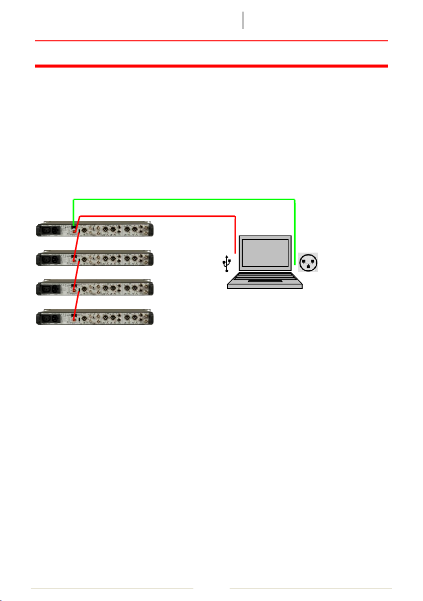
Connection
Wisycom Manager software allows to monitor and configure remotely complex systems based
on MRK950/960 connected in USB chain or thru Ethernet connection.
Basic Operation
First start
On the first startup, if no Wisycom USB device is connected to the PC, the software asks if you
want to enable it in demo mode or if you want to search all the remote-controlled Wisycom
devices you have connected. If you choose to go in demo mode, the software simply shows a
simulated system. If you choose to rescan the network, the software will open automatically
the addresses setup window, where you can access and modify the network configuration. If
you connected an USB device (i.e. MRK950 receiver), the software goes to the main window
and connects the found device.
rev02
MRK950-MRK960 Manager
Pag. 2
❶
❷
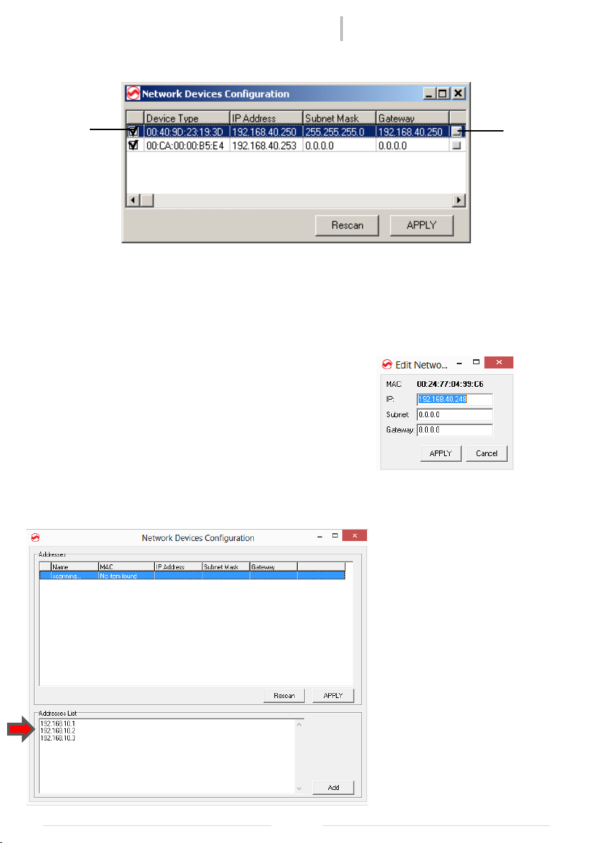
Network Addresses Setup
Figure 1: Addresses configuration window
REMEMBER: MRK9xx has a static IP, the IP address set in factory as default is 192.168.10.1/x.
Check on the label on the rear panel
The Network Devices Configuration window is useful to scan the network for available
Wisycom Ethernet devices and to configure it. In a period of some seconds, the software
collect information about all compatible systems on the
network and show a list of them.
At this moment, it is possible to access the IP configuration
window by clicking on the small gray icon on the right ❶.
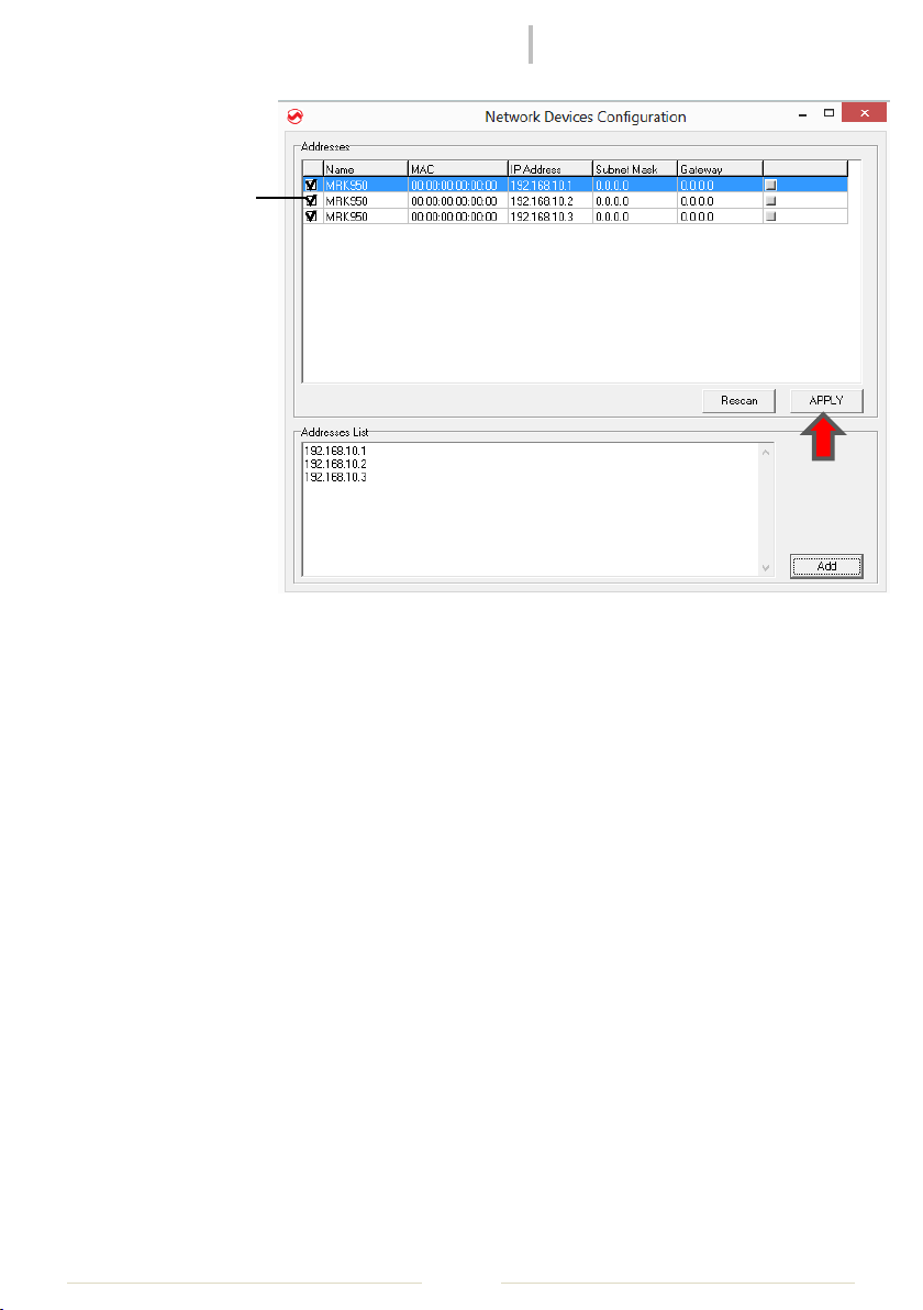
When the configuration is done, the user can choose which network devices include on the
management with the checkboxes on the left ❷. The list of the enabled devices will be saved
on the configuration file, and will be reused also in the next executions of the software, unless
this configuration is redone in
the future, accessing the form
in File->Addresses on the
menu.
In case of the device doesn’t
compare during the scan, it is
possible to insert manually the
IP address in the box named
“Address List” (this feature is
available only in the latest
versions of WM).
Insert the list of the IP address
and push the button Add.
rev02
MRK950-MRK960 Manager
Pag. 3
❷
Select the
devices to
include on the
management
clicking on the
checkboxes
on the left
❷, and push
APPLY button.
Modes of use: Live and Edit
This software allows two different modes of use.
The LIVE mode, enabled by default on startup, allows any configuration change done by the
software user to have immediate effect on the device. Any parameter modified on any edit
window will be directly saved on the system, and will be effective.
The EDIT mode allows the user to change the configuration of a system without rendering it
immediately active. In this way it is possible to prepare an alternative to the actual
configuration, that can be saved on file and reloaded in a second time, or simply doublechecked before to be effective.
It is possible at any time to switch between live and edit mode. If some configuration has
changed while the user was in edit mode, switching to live mode the user can choose if the
new parameters has to be uploaded on the device to effective, or simply discarded.
The main window
In the main window you can access and monitor all the device connected by the software
(using both Ethernet and USB connection).
The main window is split vertically in two sections.

rev02
MRK950-MRK960 Manager
Pag. 4
ON THE LEFT a tree-structured view gives the ability to easily understand the structure and
composition of the connected systems. In fact, for every different connection to the PC (IP
address or USB post), in the manager is associated a main system, where single receivers or
accessories (accessible through the single connection) are leafs associated to the respective
main node. In the tree-view the main systems are shown as root nodes, while single receivers
are leafs. To every system is associated a different color (chosen from a list in the
configuration file), that allows easy recognition of the parent system of every single receiver
graphical module.
Selecting a single node and pressing the right button of the mouse, a popup menu appears,
showing a list of actions possible with the selected item.
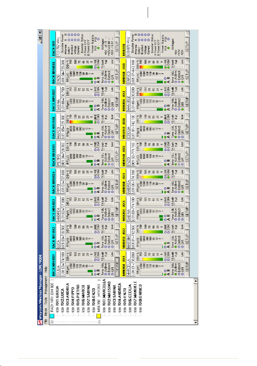
ON THE RIGHT are visualized the graphical modules of the receivers, of the racks and of the
accessories connected. Every module can be moved using a single drag-and-drop operation
inside the blue-gray panel. The position of the modules is “snapped” along an invisible grid, to
easily maintain the visualization panel in order. The height of every row of modules can be
reduced or pulled back to normal condition, using the small button at the bottom-right of any
module, in order to increase the number modules that can be visualized on the screen at the
same time.
rev02
MRK950-MRK960 Manager
Pag. 5
Figure 2: Main window example with two fully populated systems connected

rev02
MRK950-MRK960 Manager
Pag. 6
Every module reproduce the aspect of the remotely monitored device. The button SETUP on
any module allow the user to access very quickly the related parameters window.
Once a particular disposition of graphical modules is obtained, it is possible to save the
workspace setup using the File->Save Workspace function. This file can be reloaded in a
second time using the File->Load Workspace function after the system components has been
connected; the graphical modules will be replaced automatically in the same disposition.
The status bar on the main window shows the status of command queues of the currently
connected systems. When a massive amount of data requests from the systems is queued, a
certain amount of time (some seconds) is required to have all the requests fulfilled.
Receiver's parameter window
The receiver's parameters window can be accessed on the popup-menu of a receiver item in
the tree window or directly on the setup button of a receiver graphical module.
Figure 3: Receivers Parameter Window

rev02
MRK950-MRK960 Manager
Pag. 7
This window shows the configuration of all the receivers present on the selected system, and
the frequencies saved in memory of the devices, relative to the group of the currently selected
receiver (the one used to open the window). Each column on the grid is related to a single
receiver. It is possible to show also frequencies of all other groups, simply selecting another
one using the drop-down listbox on the top-left angle of the window.
The blue thin rectangle surrounding one of the columns highlights the receiver that was
selected to open the parameters window of this system. The frequency group of this receiver
was used to pre-select the channel group shown on this window.
The yellow background color of some cell, if present, means that the receiver related to the
column, where the yellowed cell is, is tuned on the channel indicated, in the channel group
currently selected. If a receiver has no yellowed cell on current visualization, it means that the
receiver is tuned on a different channel group. The user can change the current channel
tuning of every receiver simply clicking with the left mouse button on the desired channel on
the grid, while keeping pressed the CTRL-key on the keyboard. If during this operation the grid
cell appears with red background, the currently tuned frequency is outside the frequency
range of the system (i.e. using an MRK920 receiver, the frequency is outside the current RF
band of the RFI module).
To change working parameters of one or more receivers, before it is necessary to choose
which receivers will be affected by the operation. Enable or disable it by clicking on the
checkboxes on the top of each grid column. In this way the columns related to enabled
receivers will have a light blue background. When operation is enabled for one or more
receivers, the user is granted to change the configuration using the mouse on the parameters
grid. All the enabled receivers will be affected in the same way by the new configuration. In
this way it is extremely easy to reprogram all the receivers of a system with the same
configuration. Double-click with the left mouse button on the frequencies cells let the user to
insert a new frequency to be saved on memory, using the frequency editing form.
It is possible to load and save over CSV file all the frequencies of a single receiver in the
current group. To access this functions simply press the right mouse button while the mouse
cursor is over one of the cells containing frequencies for the desired receiver. A popup menu
will appear; simply choose if you want to load or to save data and then the filename to be used
for the operation.
Rack's parameter window
The system parameters window can be accessed on the popup-menu of a rack item in the
tree-view or directly through the setup button of a rack graphical module.
rev02
MRK950-MRK960 Manager
Pag. 8
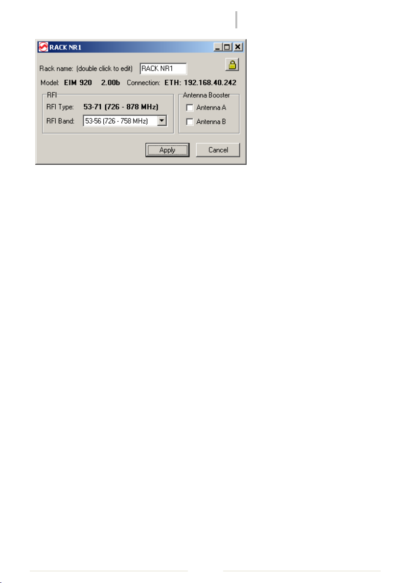
Figure 4: Rack Parameter Window
In this window it is possible to change the rack configuration (when available).
It is possible to edit the rack name by double-clicking inside the edit box and typing a new
name.
The selection of the working range of the system, when more than one is available, can be
done using the RFI band drop-down list.
With the Antenna Booster checkboxes is possible to turn on and off the power supply sent to
the remote antenna booster (when used).
If on the top-right edge of the form appears a small button with a locker, the system you are
using supports password protection. Clicking it a dialog box for the insertion of a new
password will appear.
Remember! When you set a password on the system, you will be asked for it on remote
connection operation! If you forget your password, you will need to disable it using an
hardware jumper inside the rack! So don't forget it!
 Loading...