

MRK950-MRK960
Manager
Products: MRK950 (options L,H,I,M)
MRK950-EX (options W,X) and MRK960
Rev: rev02 (ref. Wisycom Manager 2010 v1.1.4.6)
Date: 23 July 2014
rev02
MRK950-MRK960 Manager
Pag. 1
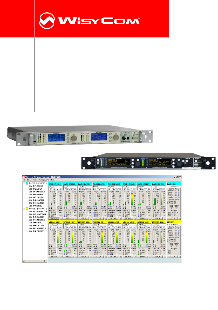
WISYCOM WIRELESS MANAGER
Wisycom Wireless Manager is a complete software designed to remotely monitor, control and
reprogram Wisycom rack receivers MRK950 and MRK960 connected using Ethernet or USB
interface.
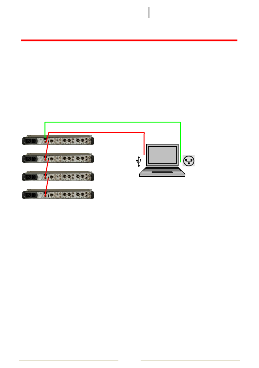
Connection
Wisycom Manager software allows to monitor and configure remotely complex systems based
on MRK950/960 connected in USB chain or thru Ethernet connection.
Basic Operation
First start
On the first startup, if no Wisycom USB device is connected to the PC, the software asks if you
want to enable it in demo mode or if you want to search all the remote-controlled Wisycom
devices you have connected. If you choose to go in demo mode, the software simply shows a
simulated system. If you choose to rescan the network, the software will open automatically
the addresses setup window, where you can access and modify the network configuration. If
you connected an USB device (i.e. MRK950 receiver), the software goes to the main window
and connects the found device.
rev02
MRK950-MRK960 Manager
Pag. 2
❶
❷
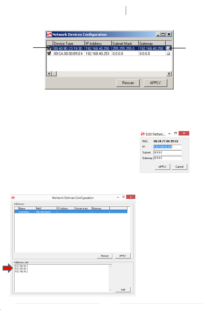
Network Addresses Setup
Figure 1: Addresses configuration window
REMEMBER: MRK9xx has a static IP, the IP address set in factory as default is 192.168.10.1/x.
Check on the label on the rear panel
The Network Devices Configuration window is useful to scan the network for available
Wisycom Ethernet devices and to configure it. In a period of some seconds, the software
collect information about all compatible systems on the
network and show a list of them.
At this moment, it is possible to access the IP configuration
window by clicking on the small gray icon on the right ❶.
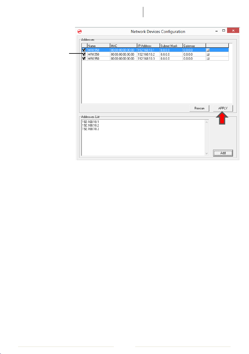
When the configuration is done, the user can choose which network devices include on the
management with the checkboxes on the left ❷. The list of the enabled devices will be saved
on the configuration file, and will be reused also in the next executions of the software, unless
this configuration is redone in
the future, accessing the form
in File->Addresses on the
menu.
In case of the device doesn’t
compare during the scan, it is
possible to insert manually the
IP address in the box named
“Address List” (this feature is
available only in the latest
versions of WM).
Insert the list of the IP address
and push the button Add.
rev02
MRK950-MRK960 Manager
Pag. 3
❷
Select the
devices to
include on the
management
clicking on the
checkboxes
on the left
❷, and push
APPLY button.
Modes of use: Live and Edit
This software allows two different modes of use.
The LIVE mode, enabled by default on startup, allows any configuration change done by the
software user to have immediate effect on the device. Any parameter modified on any edit
window will be directly saved on the system, and will be effective.
The EDIT mode allows the user to change the configuration of a system without rendering it
immediately active. In this way it is possible to prepare an alternative to the actual
configuration, that can be saved on file and reloaded in a second time, or simply doublechecked before to be effective.
It is possible at any time to switch between live and edit mode. If some configuration has
changed while the user was in edit mode, switching to live mode the user can choose if the
new parameters has to be uploaded on the device to effective, or simply discarded.
The main window
In the main window you can access and monitor all the device connected by the software
(using both Ethernet and USB connection).
The main window is split vertically in two sections.

rev02
MRK950-MRK960 Manager
Pag. 4
ON THE LEFT a tree-structured view gives the ability to easily understand the structure and
composition of the connected systems. In fact, for every different connection to the PC (IP
address or USB post), in the manager is associated a main system, where single receivers or
accessories (accessible through the single connection) are leafs associated to the respective
main node. In the tree-view the main systems are shown as root nodes, while single receivers
are leafs. To every system is associated a different color (chosen from a list in the
configuration file), that allows easy recognition of the parent system of every single receiver
graphical module.
Selecting a single node and pressing the right button of the mouse, a popup menu appears,
showing a list of actions possible with the selected item.
ON THE RIGHT are visualized the graphical modules of the receivers, of the racks and of the
accessories connected. Every module can be moved using a single drag-and-drop operation
inside the blue-gray panel. The position of the modules is “snapped” along an invisible grid, to
easily maintain the visualization panel in order. The height of every row of modules can be
reduced or pulled back to normal condition, using the small button at the bottom-right of any
module, in order to increase the number modules that can be visualized on the screen at the
same time.
rev02
MRK950-MRK960 Manager
Pag. 5
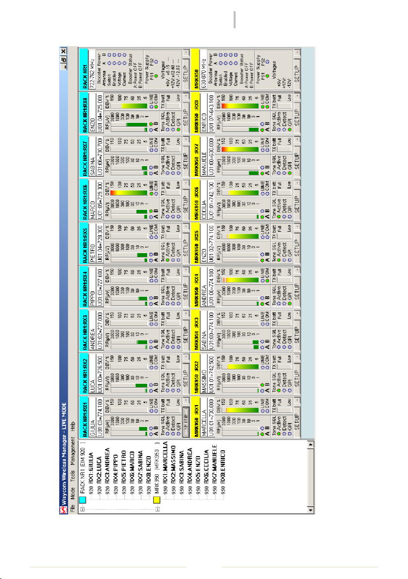
Figure 2: Main window example with two fully populated systems connected

rev02
MRK950-MRK960 Manager
Pag. 6
Every module reproduce the aspect of the remotely monitored device. The button SETUP on
any module allow the user to access very quickly the related parameters window.
Once a particular disposition of graphical modules is obtained, it is possible to save the
workspace setup using the File->Save Workspace function. This file can be reloaded in a
second time using the File->Load Workspace function after the system components has been
connected; the graphical modules will be replaced automatically in the same disposition.
The status bar on the main window shows the status of command queues of the currently
connected systems. When a massive amount of data requests from the systems is queued, a
certain amount of time (some seconds) is required to have all the requests fulfilled.
Receiver's parameter window
The receiver's parameters window can be accessed on the popup-menu of a receiver item in
the tree window or directly on the setup button of a receiver graphical module.
Figure 3: Receivers Parameter Window

rev02
MRK950-MRK960 Manager
Pag. 7
This window shows the configuration of all the receivers present on the selected system, and
the frequencies saved in memory of the devices, relative to the group of the currently selected
receiver (the one used to open the window). Each column on the grid is related to a single
receiver. It is possible to show also frequencies of all other groups, simply selecting another
one using the drop-down listbox on the top-left angle of the window.
The blue thin rectangle surrounding one of the columns highlights the receiver that was
selected to open the parameters window of this system. The frequency group of this receiver
was used to pre-select the channel group shown on this window.
The yellow background color of some cell, if present, means that the receiver related to the
column, where the yellowed cell is, is tuned on the channel indicated, in the channel group
currently selected. If a receiver has no yellowed cell on current visualization, it means that the
receiver is tuned on a different channel group. The user can change the current channel
tuning of every receiver simply clicking with the left mouse button on the desired channel on
the grid, while keeping pressed the CTRL-key on the keyboard. If during this operation the grid
cell appears with red background, the currently tuned frequency is outside the frequency
range of the system (i.e. using an MRK920 receiver, the frequency is outside the current RF
band of the RFI module).
To change working parameters of one or more receivers, before it is necessary to choose
which receivers will be affected by the operation. Enable or disable it by clicking on the
checkboxes on the top of each grid column. In this way the columns related to enabled
receivers will have a light blue background. When operation is enabled for one or more
receivers, the user is granted to change the configuration using the mouse on the parameters
grid. All the enabled receivers will be affected in the same way by the new configuration. In
this way it is extremely easy to reprogram all the receivers of a system with the same
configuration. Double-click with the left mouse button on the frequencies cells let the user to
insert a new frequency to be saved on memory, using the frequency editing form.
It is possible to load and save over CSV file all the frequencies of a single receiver in the
current group. To access this functions simply press the right mouse button while the mouse
cursor is over one of the cells containing frequencies for the desired receiver. A popup menu
will appear; simply choose if you want to load or to save data and then the filename to be used
for the operation.
Rack's parameter window
The system parameters window can be accessed on the popup-menu of a rack item in the
tree-view or directly through the setup button of a rack graphical module.
rev02
MRK950-MRK960 Manager
Pag. 8
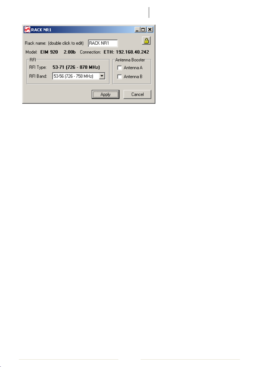
Figure 4: Rack Parameter Window
In this window it is possible to change the rack configuration (when available).
It is possible to edit the rack name by double-clicking inside the edit box and typing a new
name.
The selection of the working range of the system, when more than one is available, can be
done using the RFI band drop-down list.
With the Antenna Booster checkboxes is possible to turn on and off the power supply sent to
the remote antenna booster (when used).
If on the top-right edge of the form appears a small button with a locker, the system you are
using supports password protection. Clicking it a dialog box for the insertion of a new
password will appear.
Remember! When you set a password on the system, you will be asked for it on remote
connection operation! If you forget your password, you will need to disable it using an
hardware jumper inside the rack! So don't forget it!

rev02
MRK950-MRK960 Manager
Pag. 9
Advanced Operation
This software allows the user to employ an hardware device for special purposes, like signal
fading analysis, spectrum analysis and special graphical management of the broadcast system.
Walk Test
The walk test graph shows the envelope of the RF signal received in any time from the
receiver, detected on the same radio signal frequency and sampled with a fixed time interval.
The user can enable this function with a duration long enough to cover by walking with the
transmitter turned-on the whole area that could be interested by the broadcast event, and to
test the effective coverage of the system, the presence of not-enough covered locations, and
the effectiveness of the diversity system. Enable RF-A and RF-B checkboxes to show Antenna-A
and Antenna-B analysis.
In normal condition, after the duration time, the test stops automatically. If Max-A or Max-B
checkboxes are enabled, the test instead continues to cycle, showing always the maximum
value that the signal reached at any time, allowing a very long lasting analysis. The operation,
even when the time interval is large, assures the quality of the measure, because also
intermediate values of the signal between two samples are evaluated.
Figure 5: Walk Test Graph Example
Using the functions available in the main menu it you can save the current graph data for
successive load and review, as well as print a graph or save it as bitmap image.
To perform a walk test analysis the user must do the following tasks:

rev02
MRK950-MRK960 Manager
Pag.
10
choose the receiver that should be used for the operation and tune it to the
interested channel
select the receiver on the tree-view and start the Walk-Test analysis from the popup
menu or from Tool->Walk Test on the main menu.
Select Duration and Interval parameters and press RUN
With this functionality it is also possible to analyze, with the transmitter turned-off, the
possible spot-presence of foreign signals on the selected channel.
To zoom a part of the graph simply click and drag the mouse with the left mouse button. To
zoom out double-click on the graph with the left mouse button. To pan click and drag with the
left mouse button, while keeping pressed the CTRL-key on the keyboard.
2D Spectrum Analysis
This function allows the user to employ a receiver like a spectrum scanner, and to build a
graph of all the signals received in a frequency range. This analysis is very useful when it is
necessary to choose a new frequency allocation or to choose the best frequency for a radio
link.
Enable RF-A and RF-B checkboxes to show Antenna-A and Antenna-B analysis, while Max-A
and Max-B checkboxes enables data traces relative to maximum signal level relative to a single
frequency. The test continues to cycle until it is stopped by the user. The operation, even if the
time between samples is large, assures the quality of the measure, because also intermediate
values of the signal between two samples are evaluated.
Using the functions available in the main menu it you can save the current graph data for
successive load and review, as well as print a graph or save it as bitmap image.
To perform a spectrum analysis the user must do the following tasks:
select the receiver to be used for the operation on the tree-view and start the 2D
Spectrum Scanner analysis from the popup menu or from Tool->2D Spectrum
Analyzer on the main menu.
Select the desired Frequency range, the Step (100/200/500 KHz , 1/2MHz) and the
Data Source for the measure and press RUN

rev02
MRK950-MRK960 Manager
Pag.
11
Figure 6: 2D Spectrum Analysis
To zoom a part of the graph simply click and drag the mouse with the left mouse button. To
zoom out double-click on the graph with the left mouse button. To pan click and drag with the
left mouse button, while keeping pressed the CTRL-key on the keyboard.
3D Spectrum Analysis
This function allows the user to employ a receiver like a spectrum scanner, and to build a
graph of all the signals received in a frequency range. This analysis is very useful when it is
necessary to choose a new frequency allocation or to choose the best frequency for a radio
link. Values measured in different instants in a cyclical way are plotted in a 3D graph, allowing
the user to understand precisely the variations of the signal levels in the time.
It is possible to choose between different sets of data to be visualized. It is possible to show
spectrum analysis done with antenna-A, antenna-B or with the maximum between the two
antennas at any time. The test continues to cycle until it is stopped by the user. The operation,
even if the time between samples is large, assures the quality of the measure, because also
intermediate values of the signal between two samples are evaluated.
Using the functions available in the main menu it you can save the current graph data for
successive load and review, as well as print a graph or save it as bitmap image.

rev02
MRK950-MRK960 Manager
Pag.
12
To perform a spectrum analysis the user must do the following tasks:
select the receiver to be used for the operation on the tree-view and start the 2D
Spectrum Scanner analysis from the popup menu or from Tool->2D Spectrum
Analyzer on the main menu.
Select the desired Frequency range, the Step (100/200/500 KHz , 1/2MHz) and the
Data Source for the measure and press RUN
Figure 7: 3D Spectrum Analysis
The graph perspective can be changed easily with a click and drag with the left mouse
button.

rev02
MRK950-MRK960 Manager
Pag.
13
❶
❷
❸
Intermodulation calculator
With Wisycom Manager it’s possible to make a frequency plan calculation intermodulations
free. To do this, select a receiver in the tree-structured view on the left and select
Management>Intermodulation Calculator menu.
First is displayed the frequency range menu where it’s possible to set up the desiderate
frequency range of calculation and the forbidden ranges if present.
In “WORKING PPARAMETERS”, the receiver working range and the frequency step
(25/50/100/200 KHz) can be changed (select Custom Range to change the receiver working
range and APPLY to confirm).
In “SELECT FREQUENCY RANGES” there are three possibility to set up the allowed and
forbidden frequency range:
❶ changing the Start/Stop frequency of calculation
❷ selecting the band of the Wisycom transmitters in the list
❸ choosing the DVB-T channel (depending on the country)
Select “Allowed range” or “Forbidden range” to add the range on the right table:
if a range is allowed, the relative cell on the first column “#” become dark green.
if a range is forbidden, the relative cell on the first column “#” become brown/red.
In the section below, there is the “Local Region Settings” where it’s possible load a specific
configuration depending on the working area (there are two list box: Region and Area).
It’s possible to create other new Region and Area:
set the allowed and forbidden ranges
save the configuration on the pc
go to C:\Users\User that had install the Wisycom Manager\AppData\Roaming\
Wisycom\Rack Rx Manager (MRK9xx)\1.1.4.5\data\FrequencyRanges

rev02
MRK950-MRK960 Manager
Pag.
14
(AppData is an hidden folder)
to create a new Region, create a new folder in FrequencyRanges and open it
to insert a new area configuration, save here the previous saved configuration
If some single frequencies must be imposed as fixed solutions or must be avoided, select
“DESIDERED SINGLE FREQUENCIES” panel, insert the desired frequencies (in KHz) and click to
Acquire to load the frequencies.

rev02
MRK950-MRK960 Manager
Pag.
15
Before starting the frequency calculation, select “NOT INTERFERRED FREQUENCY RANGES”
panel to load a previous frequency scan (.csv file) or make a new one in the allowed ranges.
In the graphic there are three bar:
a dark green and brown/red bar that show the allowed (dark green) and forbidden
(brown/red) ranges set in the first panel
an alternating blue and grey bar that show the DVB-T channels
a light green bar in the allowed ranges that become red where the RF level > Squelch
level (settable in the squelch box under the graphic). During the calculation of the
frequencies, the calculator will consider only the frequency range where this bar is
light green
The new scan can be saved with Save Scan

rev02
MRK950-MRK960 Manager
Pag.
16
❶ ❷ ❸
❹
❺
Select “FREQUENCY CALCULATOR” panel to set up the calculation of the frequencies and start
it.
❶ - Use Frequency SCAN: check it to use the frequency scan show in “NOT INTERFERRED
FREQUENCY RANGES” panel (this parameter can be set only after loading a scan or at the
end of a new one)
- Use Digital Intergap Only: check it if you want that the calculator must calculate the
solutions only in the intergap between two DVB-T channels
- Use Digital Intergap First: check it if you want that the calculator must calculate first the
solutions in the intergap between two DVB-T channels and then, when there are no
other solution in the intergap, in the remain allowed range.
- Skip Analogue Carriers
- Avoid Mixer Spurious: this list box permit to avoid mixer spurious when a receiver is used
near a transmitter. It’s possible to choose:
- “No Mixer Spurious” to not use this function;
- “MCR42 Mixer Spurious” to avoid mixer spurious using an MCR42;
- “MRK960 Mixer Spurious” to avoid mixer spurious using an MRK960.
- Select Frequency Layout: this list box permit to choose the layout of the solutions
between four choices: preferring the lower or higher frequencies, with an uniform
spread or preferring the frequencies with lower RF power.
❷ Check Internal Range if you want that the calculator must calculate first the solutions in a
specific Center TV Channel settable in the relative list box. With Iteration Timeout [sec] it’s
possible to set the time to wait for the calculation of solutions in the Center TV Channel
selected.

rev02
MRK950-MRK960 Manager
Pag.
17
❸ In the frequency criteria box, there are the parameters about rules for calculation of the
solutions:
- Other Carrier: indicate the minimum distance from a solution carrier to another.
- Avoid Carrier: indicate the minimum distance of a solution carrier from an avoid
carrier.
- Intermod 2(TX): indicate the minimum distance between the solutions carriers and
the intermodulations products that are generate when there are 2 TX near.
- Intermod 3(TX): indicate the minimum distance between the solutions carriers and
the intermodulations products that are generate when there are 3 TX near.
- Forbidden Areas: indicate the minimum distance of the solutions carriers from a
forbidden area.
Another parameter in this box is the “Intergap BW” that indicate the intergap bandwidth
between two TV channel.
Under “Intergap BW” there is the Protection Level list box where it’s possible to set one of
the four preloaded protection configurations (High, Medium, Low or Low (2TX Only)) or
the Custom configuration (only with “Custom” it’s possible to change the values).
We advise to use an high protection to avoid any intermodulation but in some cases, with
an high protection, the program can find few solutions. In these cases, if are necessary
other solution, it's possible to reduce the protection to try to find more solutions.
❹ Here it’s possible to set the number of solutions that the calculator must found and START
the calculation. The solutions found appear in the right column on the “FREQUENCY
CALCULATOR” panel and the number of frequencies found is written in “Found Solutions”
❺ In the Save box the solutions found can be saved as a wdf. file:
- Select SAVE as WDF
- Select as Group# the first free group on the rx/tx
- Give a name and descriptionn to the plan
- Select lock Channels: in this way the user can not modified the group only using
Wisycom Manager (MRK960) o IR Programmer (MTPxx, MTHxxx)
- Push SAVE button

rev02
MRK950-MRK960 Manager
Pag.
18
After the calculation of the solutions, going back to the “NOT INTERFERRED FREQUENCY
RANGES” panel to view the results in the graphic (to show the results, check “Draw Results”
under the graphic). It’s possible to zoom the graphic simply selecting the desiderate
Setup Copy/Import/Export
The user can easily copy/import/export the whole configuration of the connected systems
between the system itself, part of that, or files. The window designed for this operation is
accessible in Management->Import/Export in the main menu.
Figure 8: Import/Export Window

rev02
MRK950-MRK960 Manager
Pag.
19
When the user accesses this tool, the software switch mode automatically to EDIT; disabling
the direct application of the modified parameters. This is done to assure a better control of
the user over the software and to avoid a destructive mis-reprogrammation of the systems.
To save effectively the new configuration to the modified systems, it is necessary to switch
manually to LIVE mode, after a check that all the data copy operations has been done in the
right way.
Source and destination can be selected between system (a physical device connected) and file.
When a file operation is chosen, the software ask the user to browse to a specific file to be
used.
In both system and file operations, on the left of the window are visualized two tree-views,
showing the structure of the system available to copy the data. In the case of a file source, the
tree-view shows the structure relative to the data that was saved in the moment of the file
creation.
Data copy is easy.
Select source and destination of the operation in the two tree-views. Both receivers and
systems can be used as source and destination, with the difference that if a receiver is
selected, the data copy will affect just the selected receiver itself, but if a whole system is
selected, the operation will be related to all the receivers in the selected system.
It is also possible to copy between a receiver on a system and a system itself, allowing the user
to fast mirror the configuration of the selected receiver to all the other.
After the source and destination selection, the group grid is repainted, showing a list of all
available source and destination frequency groups. By default each group is disabled for copy
and the target group is the same as the source group. The user has the ability to change the
destination of frequency program on different groups, using the drop down lists on the central
column of the grid, and to choose which groups must be copied, with the checkbox on the
rightmost column. Beside the frequency data, the user can choose to copy also other receivers
and system data selectively, like Name, Channel, PTT configuration, NR System, and so on...
When all the copy setup is ready, press GO.
The routine can be restarted several times to repeat the operation with different parameters,
to achieve special data treatments.

rev02
MRK950-MRK960 Manager
Pag.
20
Saving & Reloading scenes
A scene is receivers configuration stored along network structure and names.
For example, let say that 4 Mrk950s are linked together through theirs USB daisy chains and
you access the last receiver with USB or network interface.
In this case the system is seen together as 8 channel rack and this system is also identified by
the rack name (that is the name associated to the last MRK950 on the chain).
In this example the structure of the system is 4 MRK950 rack and this is identified by last
MRK950's name (not that you can setup the then name on the rack parameters windows).
Of course more complex structures are allowed (ie.many rack of 4 MRK950's and MRK920's).
On your system is setup correctly you have to name properly all rack sets using the rack
parameters windows (ie. first 4 MRK950 rack in main studio named "main", 2 MRK950 rack in
the lobby named "lobby"). Once again for each rack this name is associated to the last
MRK950 which is the master, and the information about the structure and all parameters are
stored matching those names!.
You can access the scene save dialog box on the main menu in File->Save Scene
Figure 9: Save scene dialog box
On save frequency data pop-up menu us can chose among:
no frequency data -> saving for each receiver current group and channel, along with
other advanced setups (like squelch, data mode).
Since this in not saving frequency tables, this is the quickest mode!
only selected group --> saving for each receiver current group and channel and the
current selected group, along with other advanced setups (like squelch, data mode).
This mode is saving the frequency tables but only on groups (50 frequencies)
associated to used frequencies.

rev02
MRK950-MRK960 Manager
Pag.
21
all groups --> saving for each receiver current group and channel and all frequency
tables, along with other advanced setups (like squelch, data mode).
This mode is saving al frequency information for each receiver, beware that is the
system is big you are saving a lot of data: 2000 frequencies for each receiver!
You can access the scene save dialog box on the main menu in File->Save Scene
Figure 10: Load scene dialog box
On load frequency data pop-up menu us can chose among:
no frequency data -> loading for each receiver current group and channel, along with
other advanced setups (like squelch, data mode).
Since this in not loading frequency tables, this is the quickest mode!
only selected group --> loading for each receiver current group and channel and the
current selected group, along with other advanced setups (like squelch, data mode).
This mode is loading the frequency tables but only on groups (50 frequencies)
associated to used frequencies.

rev02
MRK950-MRK960 Manager
Pag.
22
all groups --> loading for each receiver current group and channel and all frequency
tables, along with other advanced setups (like squelch, data mode).
This mode is loading all frequency information for each receiver, beware that is the
system is big you are saving a lot of data: 2000 frequencies for each receiver!
On Receiver data box us can chose also select what addition parameters you want to overload
(ie. squelch ... ). All modifications are stored in the .ini file and you can restore the initial list
using the default button.

rev02
MRK950-MRK960 Manager
Pag.
23
Software Configuration
The software supports several user-modify parameters, that modify the graphical aspect as
well as the way some function will work.
You can access the configuration dialog on the main menu in Tools->Options.
Figure 11: Software options dialog
You can change the colors of all the main windows/graphs that appear on this software. You
can also change the sequence of the colors that will be assigned in incremental way to the
remote systems.
About graphical parameters of the movable graphical panels on the main window, you can
specify a threshold value for the RF bars. If the value of the signal level is below the specified
value, the RF bar will be turned off. This is useful if you want to understand with fast eye-look
if you signal is over a desired level or not. You can also specify if you want to show bar peaks,
and how fast they must be.

rev02
MRK950-MRK960 Manager
Pag.
24
In system authentication you can specify to clear the cached password that can be used for
system authentication. To clear the list of passwords enable the checkbox and click the apply
button.
Enabling Load Out Frequencies (Lock->Hidden) on Channel Files panel, it is possible to load
frequencies out of the allowed range of the MRK9xx. The locked frequencies out of the range
will be automatically hidden.
The Master/Slave Control panel allows to enable the monitoring from other PCs (available
from Wisycom Manger version 1.1.4.0). In the Master/Slave configuration, only one PC works
as Master and can change the configuration of the receiver, the other PCs work as Slave and
can only monitoring the receiver.
The PC that works as Master is the first PC connected to the
receiver. To enable the monitoring from other PCs is
mandatory to click on Enable Local Server.
The other PC that works as Slave, have to activate the
option Enable Connect as Client (slave).
From the Master PC is possible to show how many PCs is monitoring the
receiver (see the parameter Clients Racks) and pushing the show button is
possible to verify the IPs of all the slave PCs connected.

rev02
MRK950-MRK960 Manager
Pag.
25
rectangle for Master PC
oval for Slave PC
From the Slave PC is possible to show the number of the PC server and pushing the show
button it is possible to verify the IPs of the Master PCs.
The icon on the left panel has different shape which identify the type of connection:
NOTE: In order to limit the IP traffic, the maximun number of slave PCs is limited to 4.

rev02
MRK950-MRK960 Manager
Pag.
26
Wisycom Manager Version
Supported Wisycom Device
Model
Firmware Version
>1.1.3.4
MRK950/MRK950EX
1.0.1.x
>1.1.2.11
MRK960
1.1.0.x
>1.1.2.0
MRK960
1.0.0.x
>1.1.1.16
MRK950
1.0.0.x
WM Version and supported Wisycom devices
Wisycom Manager supports different models of MRKxxx. See in the table below in what
version of WM it was added the compatibility to the specific model and firmware version.
Anyway it is advisable to install the newest version of Wisycom Manager and upgrade the
MRKxx receiver to the last firmware version. For more details visit the Download section on
the website www.wisycom.com.
 Loading...