

Page 1
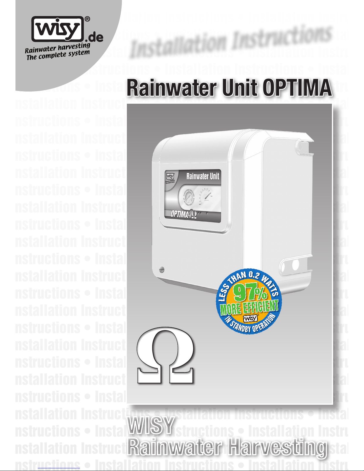
● With automatic
mains water
top-up
● Numerous individual
devices combined
to form a single
coordinated
package
● Reliable, userfriendly, cost-saving
system
● Innovative,
hydromechanical
operating principle
● Supplied ready
to connect
● Energyefficient
technology,
consumes less
than 0.2 watts in
standby operation
WISY
Rainwater Harvesting
Rainwater Unit OPTIMA
ΩΩ
OPTIMA
Installation Instructions
Page 2
2
30 %
5 %
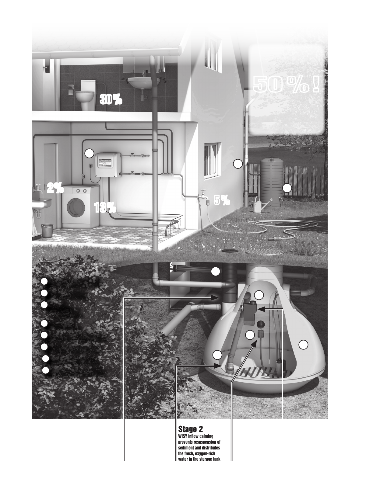
Harvesting rainwater
reduces mains water
consumption by:
50 %!
WC:
30 %
Laundry:
13 %
Garden irrigation: 5 %
Cleaning:
2 %
13 %
2 %
1
Vortex fine filter (WFF)
2
Inflow calming
3
Floating
suction filter
4
Multisiphon
5
Rainwater storage tank
6
Sigma rainwater unit
7
Filter collector (FS)
8
Rainwater barrel 500 l
Stage 2
WISY inflow calming
prevents resuspension of
sediment and distributes
the fresh, oxygen-rich
water in the storage tank
Stage 3
Water is extracted with
the WISY floating suction
filter suspended
at the optimum height
Stage 4
Overflow with skim effect,
odour seal, small animal
guard and backflow prevention with WISY multisiphon
The WISY 4-stage
rainwater cleansing
system
6
7
8
1
4
2
3
5
The WISY 4-stage rainwater cleansing principle in the single-family home
Stage 1
Filtering with WISY
vortex fine filter with
separation of dirt particles
and oxygen enrichment
Page 3
3
OPTIMA Rainwater Unit
Please read through these installation
instructions carefully before you attempt
to install and use the rainwater unit!
These installation instructions include the following information relating to:
● Applications
● Handling and storage instructions, scope of delivery
● Components diagram
● Preparations for installation, assembly
● Commissioning
● Design and operating principle
● Maintenance, safety instructions, repairs
● Troubleshooting guide
● Technical data
● Guarantee conditions, device number
● Environmental guidance
● Declaration of conformity
Read the operating instructions
carefully before commencing
assembly and installation work
and store them in a safe place for
later reference. Follow the safety
instructions on page 10!
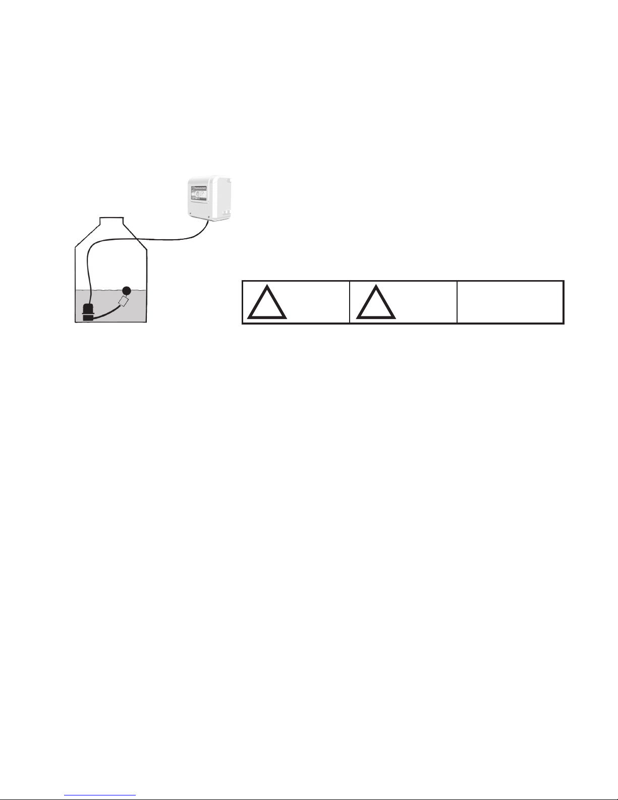
Failure to heed the information indicated by this
symbol could result in
serious or fatal injury.
Failure to heed the
information indicated by
this symbol could result
in death by electric shock.
Failure to heed the information indicated by this symbol could result in
damage to the equipment, or damage
caused by the equipment.
!
!
!
Applications
The OPTIMA rainwater unit by WISY is the control centre of the rainwater harvesting system. It is generally installed in a basement, cellar or utility room. It
comprises numerous individual devices which are combined to form an integrated, coordinated package.
OPTIMA pumps the rainwater out of the storage tank and feeds it under pressure
into the rainwater supply circuit.
At the same time, the OPTIMA controls the entire rainwater harvesting system,
checks the fill level of the storage tank and tops up the system with mains (drinking) water when required.
The Optima unit can be supplied with an optional level indicator.
The normal standard version of the rainwater unit (either 4.5 or 5.7 bar system pressure) is suitable for use in detached/semi-detached houses (up to three storeys).
Delivery / shipment of the unit
The standard version of the Optima unit is generally shipped as a parcel containing
two cardboard packages. The cardboard packages must not be dropped, crushed
or handled with force. As soon as the packages are received, they must be chekked for any signs of damage.
The cardboard packages or their contents must be stored in a safe, dry and frostfree location.
Scope of delivery
●Normal-suction, multi-stage centrifugal pump with automatic switch and pressure indicator: Max. operating pressure: 4.5 bar or 5.7 bar (in rainwater operation).
●Automatic mains water top-up (to DIN EN 1717) of integrated top-up tank (9
litres) when rainwater runs out, with float valve, dirt filter and safety emergency
overflow (DN 70).
●Cover (optional), white, to protect the rainwater unit.
●Wall mounting kit.
●Level indicator (optional) for the storage tank, with measuring lead (13 m) and
connection kit.
●Separate submersible (loading pump) with 15 m connecting cable for the storage tank, fixed vertical float switch for dry run protection and floating fine suction filter (FFSF).
Wall unit
Storage tank equipment
Contents
With floating fine
suction filter
Page 4
4
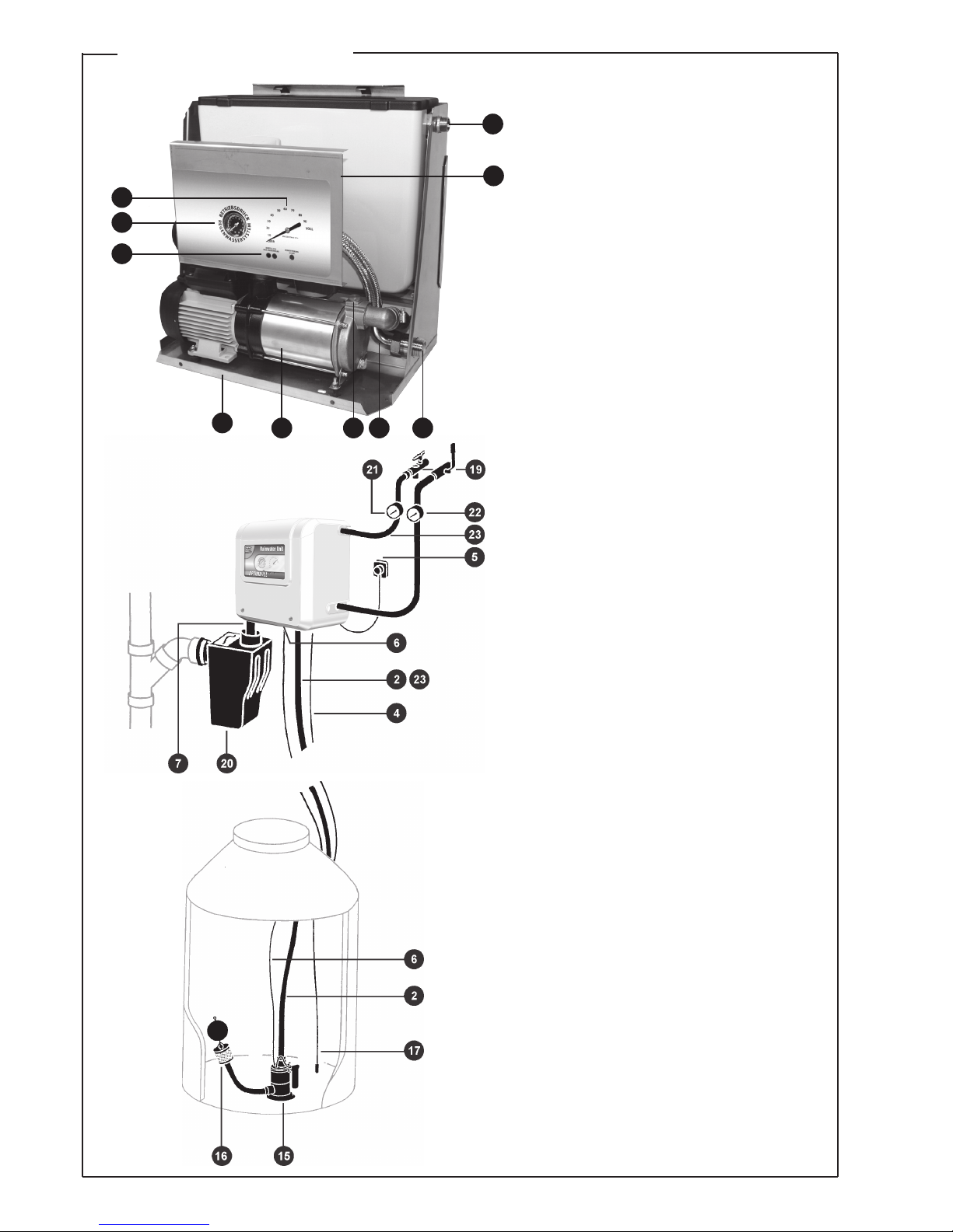
1 Mains water connection (top-up)
2 Pumped rising main (submersible pump)
3 Pressurized outlet
4 Measuring lead for level indicator
5 Mains plug for complete system
6 Electrical connection (blue socket)
for submersible pump
7 Emergency overflow drain connection (DN 70)
8 Adjusting screws for level indicator:
a) Left-hand screw: Fill level adjustment
b) Right-hand screw: Zero-point calibration
9 Level indicator
10 Operating pressure indicator
(pressure gauge)
11 Normal-suction centrifugal pump
12 Automatic switch (with display
and operator panel)
13 Base frame
14 Connecting hose to pressurized outlet
15 Submersible pump with float switch
16 Floating fine suction filter (FFSF)
17 Measuring lead in storage tank, with weight
18 Screw plug for venting/filling
Accessories not included in the
scope of supply:
19 Isolating valves for mains water pipe
and rainwater circuit
20 Multisiphon (odour seal and
backflow prevention)
21 Water meter/mains water top-up
22 Water meter/rainwater
23 Flexible connecting hoses
Illustration does not show connecting kit for
extending the electric cable
Guide to components
1
8
9
10
12
3141811
13
Page 5
5
Preparations for installation
The OPTIMA rainwater unit should be installed by a specialist installation company. This is a basic requirement for maintaining the validity of the manufacturer‘s
guarantee.
Please note: The OPTIMA must be installed above the backflow level. Special
protective measures must be implemented if the unit is installed and operated
below the backflow level!
If the maximum fill level of the storage tank is higher than the bottom edge of
the installed OPTIMA wall unit, the pumped rising main connection at the wall
unit must be equipped with a solenoid valve (normally closed) and possibly an
isolating valve (for service work). The solenoid valve is opened only when the
loading pump is started.
If a reliable, permanent connection cannot be made between the emergency overflow of the mains water top-up tank and a domestic drainage
connection, a floor Drain must be provided.
The water column between the pump integrated in the wall unit and the highest
operating point (valve at appliance) must not exceed 15 m!
Piping or hoses must be cleaned or flushed through before use to remove any
deposits of dirt/dust caused by building work!
If the OPTIMA unit is to be operated with a level indicator, it must be ensured
that the measuring lead can be installed with a continuous fall.
Important: The protective plugs fitted over the connectors on the wall unit
and the submersible pump must be removed before hoses or pipes are
connected to the units!
Assembly
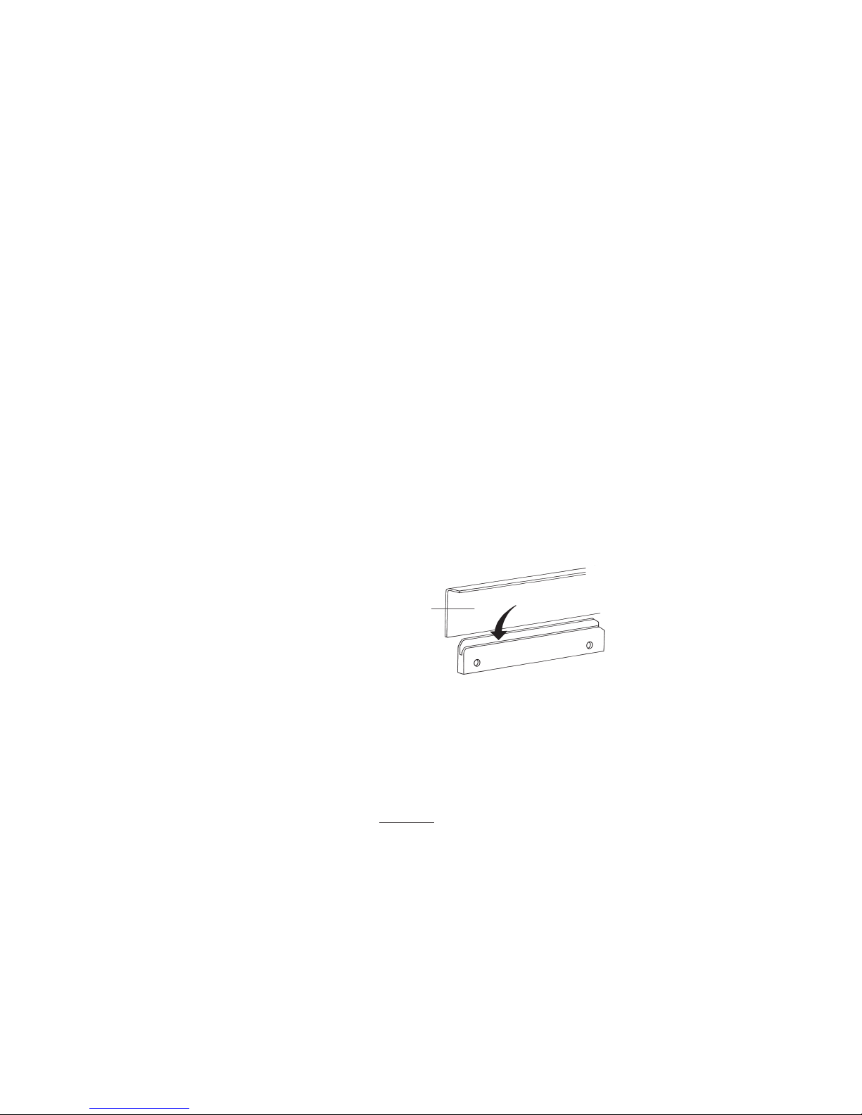
● Attach the wall mounting kit horizontally according to the dimensions given.
The wall-mounting bracket can be used as a drilling template; the distance
between the two holes is 280 mm. The rainwater unit can then simply be
inserted in the groove of the bracket.
● We recommend the use of our hose connection kit (Item No. RW 7800) to
connect the wall unit. Furthermore, all connections on the wall unit must be
flat-sealing.
●Connect the incoming mains water pipe to the mains inlet connector on the
OPTIMA unit. Use a ¾” connecting hose with stainless steel sheath (accessory) to connect the mains water pipe to the mains inlet connector on the
OPTIMA wall unit. The top-up flow rate is approximately 95 l/min with a mains
pressure rating of 3 bar (= 300 kPa).
●Important: If the mains pressure rating at the installation site is less than 3 bar
(= 300 kPa), it may be necessary to increase the cross section of the mains
pipe (e.g. to 1”). If the mains pressure rating is higher than 5 bar (= 500 kPa),
it may be necessary to install a pressure reducing valve in order to limit the
flow pressure to between 4 and 5 bar (= 400 to 500 kPa). Please consult
your installation specialist or contact WISY AG directly. It is also advisable to
install an isolating ball valve (with dirt trap) between the mains water supply
and the connecting hose to the wall unit
●Connect the emergency overflow (DN 70) of the mains water top-up tank using an odour seal (siphon) to a domestic drainage connection or feed it back
to the storage tank.
●If the unit is installed below the backflow level, an additional backflow prevention device (multisiphon) must be provided. l Connect the OPTIMA unit to the
household rainwater circuit using a flexible connecting hose and an isolating
ball valve with drain valve (accessory). In order to record water consumption, it is advisable to fit a water meter in the pressurized rainwater outlet
hose and the mains water top-up hose, as shown in the illustration.
Note regarding the backflow
level and essential installation
conditions
Assembling the wallmounting bracket
Installing the wall unit
Top
rear panel
of casing
Note height of top
edge of unit
Insert
!
!
Page 6

6
Electrical connection
●In order to record water consumption, it is advisable to fit a water meter in
the pressurized rainwater outlet hose and the mains water top-up hose, as
shown in the illustration.
●Place the pump with float switch and fine suction filter in a vertical position on
the base of the storage tank!
●Important: Never lift or pull the submersible pump by the cable! Please use
the plastic carrying strap (supplied with the unit)! Use a pressure hose or a
rigid PE pipe to connect the submersible pump to a flexible connecting hose
(accessory) of the rainwater unit (diameter of pressure hose 1”). Do not install
any flow resistances (e.g. water meters, backflush filters) in the pumped rising main between the loading pump and the wall unit.
● The mains electrical connection of the OPTIMA unit (alternating current,
single-phase, 50 Hz, 230 V) must be protected by an earth-leakage circuitbreaker (0.03 A) and a 16 A fuse. It is essential that all electrical installation
work is carried out in compliance with the relevant safety regulations!
●A blue socket is provided on the underside of the wall unit to connect the
electrical supply to the submersible pump (loading pump). No other item of
equipment may be connected to this socket! The loading pump must not be
connected to the electrical supply at the wall unit until the pump has been
vented.
●If the mains connection cable of the wall unit becomes damaged, a replacement cable must be obtained from the manufacturer, from a service partner
or from an authorized specialist supplier.
Option: OPTIMA with level indicator
This description applies to installation of an optional, pneumatic level indicator
in the OPTIMA unit. The function descriptions of the measuring instrument, the
installation instructions for the measuring lead and the device setting instructions are all important.
Scope of supply of the connection kit for the level indicator
(basic equipment)
10 m PE measuring lead (yellow), a brass hose coupling, 3 m rubber-insulated
tube (black) with brass weight and a connection kit for the measuring lead (small
parts supplied in small plastic bag). Extension sets, each containing 10 m of PE
measuring lead with brass hose coupling, can be ordered (WISY Item No. FA
9915.
Description of function
A measurement of the fill level of the storage tank is triggered only if both
of the OPTIMA pumps start up (in rainwater operation), or if only the pump
in the wall unit starts up (in mains water operation).
During the pneumatic measuring process, the hydrostatic ground pressure
is measured. This varies depending on the water level in the tank. The pressure is generally measured at a height of around 5 cm above the tank base
and is converted to the required physical unit on the clock dial. The standard
clock dial shows the fill level in %. The pump of the measuring instrument is
used to build up pneumatic pressure in the measuring system until this pressure is equal to the water pressure applied to the base of the tank. The needle is now in its maximum position. The pressure generated by the pump has
displaced the water column from the measuring lead suspended in the water
(black rubber hose). Bubbles of air escape from the end of the hose on the
tank base and the needle remains temporarily in the measurement position.
Once the OPTIMA has returned to its „normal position“, the needle gradually drops back to the „0“ position.
Installing the submersible pump
Page 7
7
Description of fill level meter
Universal, pneumatic fill level meter with capsule-type element and integrated
electric pump for measuring fill levels in tanks. Steplessly adjustable to tank
heights of between 100 cm and 250 cm (adjustable by the hexagon socket head
screw). Zero-point calibration of needle (with the Phillips-head screw). Measuring accuracy of the measurement mechanism is +/- 3% of full scale value. The
electrically operated pump closes the measuring system at the top dead point.
The needle remains stationary briefly and then drops very slowly down to its 0
position. The water stop air cushion produced in this way protects the capsule
element. Universal connection for the measuring lead (PE tube) with 8 mm outer
diameter or for the end fittings. Standard version indicates fill level as % irrespective of the tank shape.
Anwendungsbereich
Standard application is for water level height in the storage tank of between 100
and 250 cm and distances of <10 m between the OPTIMA wall unit with fill level
meter and the storage tank (measuring lead length 13 m). Remote indication
possible over distances of up to 50 m. Position of normal use: vertical. Ambient
temperature: -5°C to +55°C. Mounting location: protected against direct exposure to weather and solar radiation.
Installation instructions for measuring Lead Install the measuring lea
(yellow PE tube) with a continuous fall towards the tank. Do not bend the lead
(to prevent water pockets!).
● Install the rubber-insulated measuring lead with brass weight in the storage
tank in such a way that it is suspended vertically and ends at approximately
5 cm above the tank base, then connect both tubes with the brass coupling.
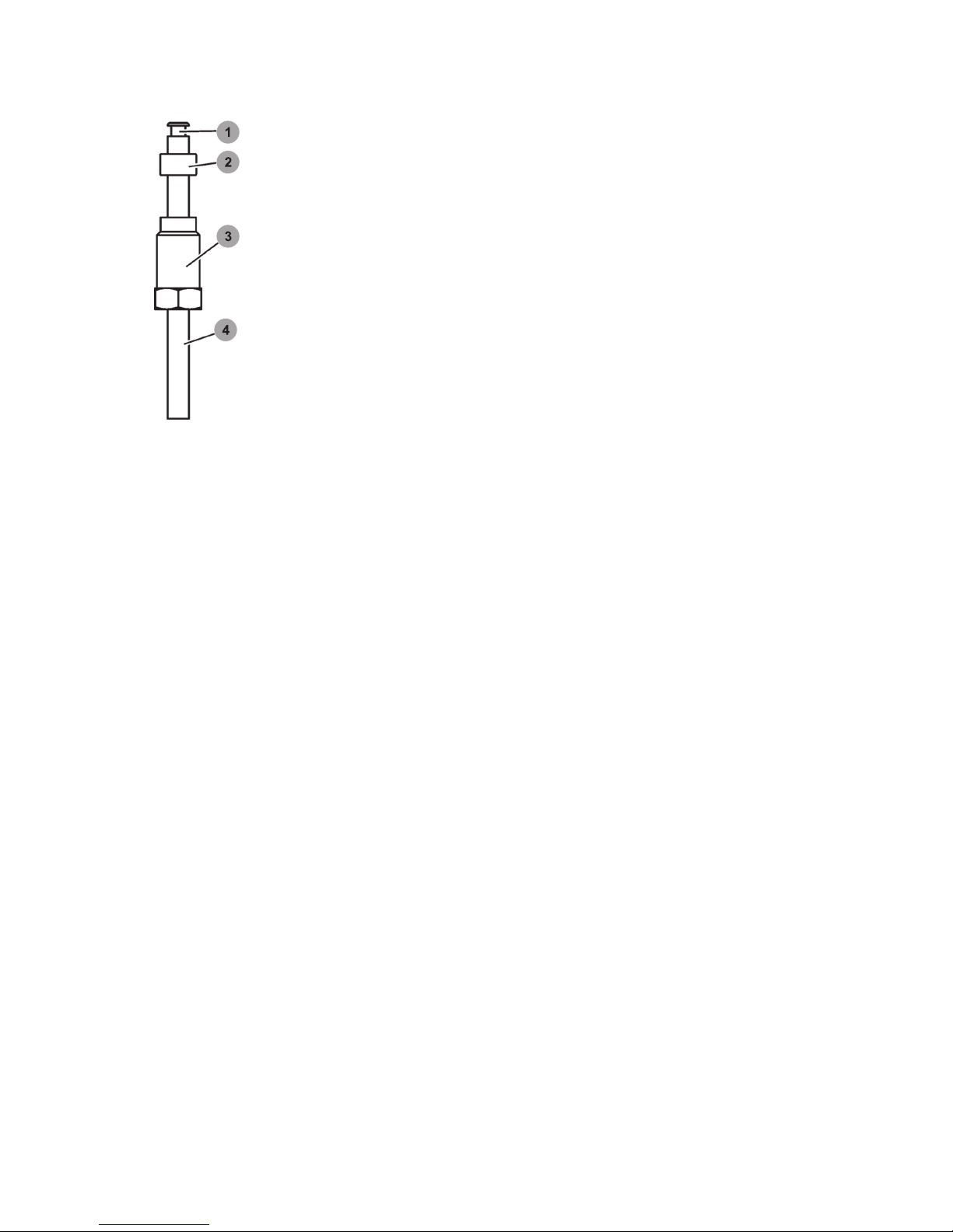
To connect the measuring lead to the measuring instrument connector (on the
underside of the OPTIMA wall unit), assemble the individual components in the
order illustrated in Figure 1 at the end of the yellow PE tube, insert the tube as
far as it will go into the connector and gently tighten the hexagon bolt.
Device setting instructions
●Remove the cover from the OPTIMA unit.
●Precisely adjust the measuring range (corresponds exactly to the Maximum
water fill level in the storage tank up to the overflow) on the adjustment scale
using the hexagon socket head screw (failure to do this properly will result in
measuring errors!).
●Use the zero-point calibration screw to position the needle at „0“. Turn the
screw by maximum one revolution to the left or right until the needle is pointing to „0“.
●If the tank has already been filled and the pump already started, the measu-
ring system will need to be „depressurized“ before the zero point can be
calibrated. This can be done by detaching the measuring lead from the
connector on the OPTIMA unit.
Indication errors and causes
●Needle does not move when measurement is taken, or drops very quickly
back to 0: Leak in connections or connecting lead. „Depressurize“ the
measuring system (see device setting instructions)! Hold a finger over the
measuring instrument connector on the wall unit and start OPTIMA by pressing the RESET button on the automatic switch (in wall unit)! If the needle
moves to its maximum position, the measuring instrument and the connections inside the wall unit up to the measuring instrument connector are OK.
The connections and connecting lead must be inspected for leaks!
●Needle moves to beyond 100% position:
The measuring lead is blocked or bent, or the measuring range
is set incorrectly.
●Indication error:
The device is incorrectly set. Check the water fill level and correct
on the adjustment scale!
1 Brass tubular rivet
(provided as „support“)
2 Rubber seal
3 Hexagon bolt (black plastic)
with hole to insert yellow
measuring lead; is screwed
into connector on wall unit
4 Yellow measuring lead
Figure 1: Connection of yellow
measuring lead to connector on
underside of OPTIMA wall unit
Page 8
8
ZETA 02 Programming
Note:
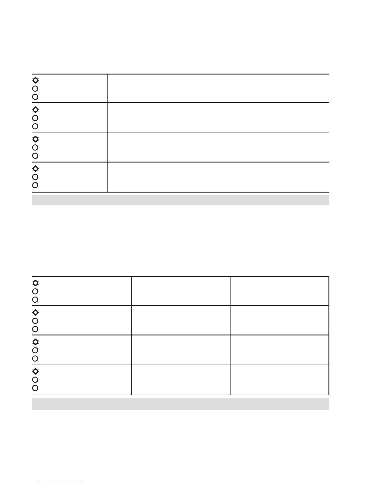
The “Reset” button on the Zeta 02 serves two functions, if pressed for less than 1 sec. it will go into reset mode, pump starts
running. If pressed for longer it will go into one of the programming modes below
Programming Run-on-time.
Mode 1 – Fast Flash
To Enter – Press and hold reset button (3 secs). Then briefly press reset button to toggle between settings.
To save the setting press and hold the reset button until the power light stops flashing (approx. 3 secs.)
FAST FLASHING
●
OFF
●
OFF
FAST FLASHING
●
ON
●
OFF
FAST FLASHING
●
OFF
●
ON
FAST FLASHING
●
ON
●
ON
10 sec Run-on-time
5 sec Run-on-time (Default and
recommended setting for normal use)
3 sec Run-on-time
1 sec Run-on-time
Programming excess pump run and starts functions
Mode 2 – Slow Flash
To Enter – Press and hold reset button (6 secs). Then briefly press reset button to toggle between settings.
D = Excess pump run function
D on – Pump stops after 10 minutes continuous run. (May need to leave this off for some irrigation applications).
T = Excess pump starts function.
T on – Pump stops after 25 starts per hour. (Where multiple starts are occurring, we would recommend installing a
pressure vessel).
Save the setting by pressing and holding the reset button until the power light stops flashing (approx. 3 secs.)
IF either of these functions has switched the pump off, THEN the fault light (only) will show. IF the fault light AND the power light
show then this indicates that a “Dry Run” type fault has occurred. (i.e. No flow arrived at the zeta 02 when the pump power was on)
SLOW FLASHING
●
OFF
●
OFF
SLOW FLASHING
●
ON
●
OFF
SLOW FLASHING
●
OFF
●
ON
SLOW FLASHING
●
ON
●
ON
D off (Default)
D off
D on
D on
T off (Default)
T on
T off
T on
Page 9

9
Important: The pumps must not be put into
operation, or even tested, unless the system is
filled with water.
Make sure that the storage tank is filled with a
sufficient quantity of water. The submersible
pump should be completely immersed in water and the float switch must be floating.
Basic operating principle
with two pressure pumps
Top-up with mains water
Commissioning
1. Venting and filling of the pump integrated in the wall unit by the loading pump:
Undo the venting/filling screw plug on the pump integrated in the wall unit;
connect only the loading pump to the electrical supply and wait until water
starts to escape from the screw plug; close the screw plug; pull out the electrical plug for the loading pump and connect to the wall unit (blue socket on
underside of the wall unit).
2. Open the valves at the appliances.
3. Connect the OPTIMA to the electricity supply.
4. As soon as system has been bled, close the valves at the appliances! The
OPTIMA unit is ready to operate as soon as the maximum system pressure
is reached.
Design and operating principle
The innovative technology of the OPTIMA is based on a hydro-mechanical control concept which combines „traditional“ control by automatic switches with
the utilization of mechanical flow effects, but without the use of any additional
electronic control components.
The OPTIMA system developed by WISY essentially operates with two pressure
pumps: The submersible pump (or „loading pump“) of the OPTIMA system is
installed in the storage tank. It is equipped with a fine suction filter and a float
switch.
The loading pump pumps the rainwater to the normal-suction, multi-stage centrifugal pump in the wall unit. As a result of the admission pressure, the centrifugal pump is required only to pump and the mains water top-up inlet pipe
remains closed.
If a valve at one appliance (e.g. toilet flushing system) is opened, the pressure in
the circuit drops. When the factory-set pump starting pressure (1.5 bar) on the
automatic switch is reached, both pumps of the rainwater unit start up. When
the valves at all appliances are closed again, the pump control system (automatic switch) turns off both pumps when the operating pressure is reached.
Note: If a „drip irrigation“ system (often computer-controlled) is to be connected
as an appliance to the OPTIMA, a small expansion vessel (around 15 l capacity)
must be installed downstream of the wall unit in the rainwater circuit. The expansion vessel used for this purpose must be of the „flow-through“ type.
Switchover to mains water top-up is fully automatic. If the storage tank is empty,
the flow switch turns off the loading pump. Since the admission pressure then
drops to zero, mains water is automatically sucked out of the top-up tank of the
OPTIMA system. The water level in the top-up tank then falls, causing the float
valve for the mains water inlet to open so that mains water can be supplied to
the centrifugal pump.
If it is necessary to temporarily operate the OPTIMA system exclusively in mains
water operation (e.g. to carry out maintenance on the storage tank), then the
loading pump need only be electrically disconnected from the wall unit (remove
plug from socket on OPTIMA unit!).
The mains water top-up system is implemented as an open outlet in accordance
with DIN EN 1717 (formerly DIN 1988/4). Furthermore, a continuous exchange of
water takes place automatically in the mains top-up tank.
The tank can be topped up with approximately 95 litres of mains water per minute if required. The mains water top-up tank has a storage capacity of 9 litres and
is also fitted with an emergency overflow (DN 70) as an additional precaution.
Every time the OPTIMA system starts up, a measurement of the tank fill level
is triggered. The clock dial indicates the level in %. When the measurement is
complete, the needle gradually drops back to the 0 position again.
A pressure gauge in the sight glass of the OPTIMA indicates the relevant system
pressure at which the rainwater unit is currently operating.
When the system is completely empty of water, the dry run protection system
integrated in the automatic switch shuts down both pumps.
Shutdown of loading pump
Water exchange in the mains water
top-up tank
Operating pressure indicator
Integrated dry run protection
Page 10

1010
Maintenance and servicing
As a general rule, the following inspections/tests must be carried out at
6-monthly intervals:
● Inspect the water circuit connections for leaks
● Perform a function test on the pumps and check the system
pressure indicator
● Test the pump start and stop points set on the automatic switch
● Check the level indicator (compare actual tank fill level with
indicated fill level)
● Perform function test on mains water top-up system, for example, by
disconnecting the electrical power supply to the loading pump at the
wall unit and opening a valve at an appliance at the same time
● Inspect the mains water inlet; if necessary, clean the dirt trap at the
inlet of the float valve and the dirt trap at the isolating valve
● Check the fine suction filter (inspect visually and clean if necessary)
● Inspect the vertical float switch at the loading pump (if necessary,
clean the filter at the casing of the vertical float switch)
If it is necessary to perform maintenance work in the storage tank, the
electrical supply to the submersible pump must be disconnected.
General safety instructions
The OPTIMA system must be installed and commissioned in compliance with
the relevant health and safety regulations. Installation work which is associated
with particular risks (e.g. protection of the mains (drinking) water supply, installation of electrical equipment) must always be carried out by properly qualified
personnel. A 230 V 1AC (50 Hz) supply voltage is required.
Failure to adhere to these instructions and/or unauthorized interference with the
OPTIMA shall exempt WISY AG from any liability for any personal injuries, property damage and/or damage to individual components of the OPTIMA system.
The OPTIMA system may be operated only with clear water (rainwater or mains
water) which does not contain any aggressive, abrasive or solid substances.
This equipment is not suitable for use/operation by persons (including children)
who suffer from any kind of physical, sensory or mental disability which might
impair their ability to safely operate the equipment, or who lack experience and/
or knowledge in the use of the equipment, unless these persons are under the
supervision of someone who is responsible for their safety or they have received
instructions from the supervising person on safe use of the equipment.
Children should be supervised to discourage them from playing with the equipment.
Repairs
All repair work must be carried out by the manufacturer or by contractors whohave been explicitly approved.
Repairs, modifications to components or modifications to the OPTIMA installation carried out by unauthorized persons shall invalidate the guarantee!
!
Im Falle von Wartungsarbeiten
bei geöffneter Zisterne ist die Optima
vom elektrischen Netz zu trennen.
Die Sicherheitsanweisungen (siehe Punkt
Sicherheitshinweise in dieser Anleitung)
sind zu beachten!
!
Page 11
1111
The OPTIMA complies with the following
technical regulations and standards:
DIN EN 1717 (formerly DIN 1988/4 Mains
water top-up via an „open outlet“), Part 1 of
DIN 1989 for rainwater harvesting systems
and other technical regulations and standards
(including safe separation of mains (drinking)
water system from rainwater circuit).
Technical data
OPTIMA 4 bar OPTIMA 5 bar
Power consumption
- horizontal centrifugal pump
- submersible/loading pump
660 W (2 HM 4)
780 W (Prov. Docvx)
850 W (2 HM 5)
780 W (Prov. Docvx)
Mains connection
1-phase alternating current
230 V, 50 Hz 230 V, 50 Hz
Total maximum power consumption for both pumps
10 A 10 A
Degree of protection
- horizontal centrifugal pump
- submersible/loading pump
- automatic switch
IP 55
IP 68
IP 44
IP 55
IP 68
IP 44
Water connections of OPTIMA
system:
-
Inlet connection of loading pump
- Mains water connection
- Outlet connection to appliances
- Suction inlet / discharge outlet
of loading pump
(OT=outside thread, IT= inside thread)
1“ OT
¾“ OT
1“ OT
1“ grommet / 1¼“ IT
1“ OT
¾“ OT
1“ OT
1“ grommet / 1¼“ IT
Sound pressure level dB
(A) (in decibels)
- in rainwater operation
- in mains water operation
52
63
57
63
Delivery head HL / flow rate Q
H
max
/ Q
min
H
max
/ Q
min (rainwater operation)
H
max
/ Q
min (mains water operation)
40.5 m / 16.6 l/min
23.8 m / 70.0 l/min
19.0 m / 60.0 l/min
51.5 m / 16.6 l/min
30.3 m / 70.0 l/min
25.3 m / 60.0 l/min
Delivery head HL at Q = 70 l/min
(loading pump)
Max. immersion depth (loading pump)
approx. 10.8 m
5 m
approx. 10.8 m
5 m
Cut-in pressure of
automatic switch
1.5 bar 1.5 bar
Max. operating pressure in RW operation
Max. operating pressure in mains operation
approx. 4.5 bar
3.5 bar
approx. 5.7 bar
4.7 bar
Max. permissible operating pressure
8 bar 8 bar
Max. water temperature 35° C 35° C
Capacity of mains water
top-up tank
9 Liter 9 Liter
Mains water connection:
- min. inlet water pressure
- max. inlet water pressure
1 bar (= 100 kPa)
6 bar (= 600 kPa)
1 bar (= 100 kPa)
6 bar (= 600 kPa)
Top-up flow rate (mains pressure
rating 3 bar (300 kPa), pipe cross
section ¾“)
approx. 95 l/min approx. 95 l/min
Dimensions of OPTIMA system
Depth x width x height (in mm)
310 x 465 x 500 310 x 465 x 500
Electr. connecting cable wall unit
Electr. cable for submersible
pump
1,5 m (3x 1,0 mm²)
15 m (3x 1,00 mm²)
1,5 m (3x 1,0 mm²)
15 m (3x 1,00 mm²)
88
Height in meters
Cable length in meters
0
1
2
3
4
5
6
7
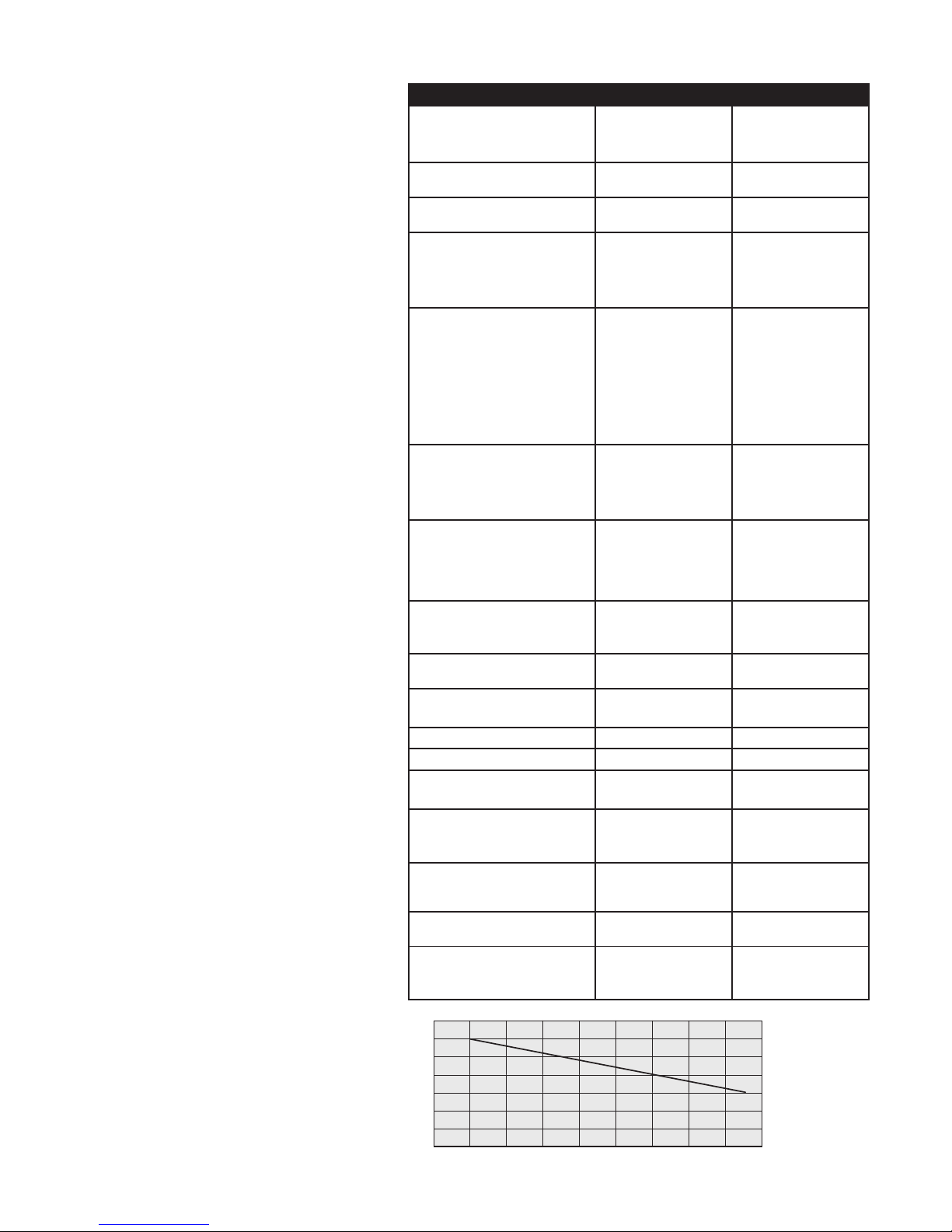
10
12 14 16 18 20 22 24 26
Ratio between Distance from loading pump
to wall unit and the maximum Delivery
height.
When greater Heights or longer pipes are
needed we recommend to use the Rainwater
unit OptimaPlus or Maxima
Page 12

12
Troubleshooting guide
Type of fault Cause Remedy
OPTIMA is not supplying
water to the appliance(s)
a) The storage tank is empty
and the mains water connection is closed (air suction,
dry run protection is active).
b) The automatic switch does
not start the pumps.
c) The pump is blocked.
d) Power supply to OPTIMA
is interrupted.
a) Absperrventil am TW-An-
schluß zur OPTIMA öffnen.
Haube abziehen und fest
installierte Pumpe über
Auffüllstutzen neu befüllen.
Schraube zudrehen. RESETTaste am Schaltautomaten
drücken. Pumpe startet und
schaltet bei max. Druck wieder aus. OPTIMA ist wieder
betriebsbereit
b) Netzstecker der OPTIMA
ziehen und wieder einstecken. Sofern die Störung
nicht behoben ist, bitte den
Kundendienst rufen.
c) Abhilfe wie unter b).
d) Elektroanschluß überprüfen
(eventuell hat der FI-Schutz-
schalter ausgelöst)!
Switchover from
rainwater to mains water
is not working and the
automatic switch is set
to „Fault“
a) The float valve in the mains
water top-up tank is blocked
or does not open.
b) The loading pump in the
storage tank has fallen over
when the water level was
low and the float switch has
not switched off the pump.
The pump is sucking in air.
c) The floating suction filter
is caught against the wall
of the storage tank and
the pump is drawing in air.
d) The loading pump is defective.
a) Check that the float valve is
operating correctly, clean if
necessary, contact customer
service if necessary.
b) Check the position of the
loading pump; if necessary,
change the pump position
or secure it in the correct
position.
c) Check the position of the
loading pump and the FFSF
set and change if necessary.
d) Contact customer service or
installation specialist.
OPTIMA is not producing
enough pressure
OPTIMA pumps have not been
fully vented.
Vent the pumps again.
Integral (centrifugal)
pump is running
continuously
a) Water loss of more than
0.7 l/min from the system.
b) Printed circuit board in the
automatic switch is defective.
a) Inspect the entire installa-
tion and the valves at all
appliances, seal and repair if
necessary.
b) Contact the installation spe-
cialist or customer service.
The integral (centrifugal)
pump is switching on
and off continuously
Leak in the system. Inspect all appliances supplied
by the rainwater circuit for
minor water losses (e.g. dripping taps, valve failing to close
completely in toilet cistern) and
repair.
Continuous top-up with
mains water despite sufficient fill level in storage
tank
a) Suction filter in submersible
pump is dirty.
b) Interruption in pumped rising
main between loading pump
and OPTIMA wall unit.
c) Interruption in electric cable
between loading pump and
automatic switch.
d) Float switch at loading pump
is blocked or defective.
e) Loading pump is defective
a) Clean external surface of
suction filter with a brush.
b) Inspect the pumped rising
main and replace if
necessary.
c) Inspect the electric cable
and replace if necessary.
d) Check whether the float
switch reaches the ON level;
contact customer service if
necessary.
e) Contact customer service.
Mains water is continuously running out through
the emergency overflow
of the mains top-up tank
(audible!)
Float valve in the mains water
top-up tank is not closing or is
clogged
Clean the valve; contact customer service if necessary.
Inadequate top-up with
mains water
The float valve in the top-up
tank is blocked or the dirt filter
at the valve inlet is clogged
Clean the float valve and/or the
dirt filter, replace if necessary
The pressure gauge
(pressure indicator) is
showing a raised pressure.
An external heat source (e.g.
radiator) is causing a pressure increase in the OPTIMA
system.
Contact customer service of
your installation company (it
might be necessary to install a
pressure relief valve).
Page 13

Materials
Horizontal, multi-stage centrifugal pump
●Stainless steel 1.4301 (pump casing, casing cover)
●Nickel-plated brass (screw plug (for filling))
●Stainless steel 1.4401 (pump shaft)
●NORYL (impeller)
●Aluminium alloy (motor enclosure)
Submersible pump
●Stainless steel 1.4301 (outer casing, motor enclosure,
bottom cover, suction foot, base plate)
●Stainless steel 1.4305 (pump shaft)
●NORYL (pump casing, handle, top bearing, impeller)
●Polypropylene (float switch)
Mains water top-up tank
●Polystyrene (tank)
●KTW-approved plastic (float valve)
Floating fine suction filter (FFSF)
●Stainless steel 1.4301 (suction strainer)
●Polyurethane (suction tube)
●Polyethylene (float)
Automatic switch
●Polyamide, polypropylene (casing)
Screw connections, pump connections, valve
●Brass, stainless steel
Connecting hoses
●Natural rubber with stainless steel braiding
OPTIMA casing
●Stainless steel (base frame)
●Polystyrene (cover)
13
Type of fault Cause Remedy
The indicated fill level
does not match the actual fill level in the storage
tank.
a) Basic setting error.
b) Measuring lead is defective
/ not leak-tight
c) Level indicator is defective
a) Refer to section Assembly/
Commissioning in Operating
Instructions.
b) Contact customer service of
your installation company.
c) Contact customer service of
your installation company.
Page 14

Guarantee
This guarantee is valid for a period of 24 months and becomes effective on the date
of purchase by the customer. Replacement of the product under guarantee will not
extend the original period of the guarantee.
WISY shall meet its guarantee obligations for the OPTIMA rainwater unit If it can be
demonstrated that the following conditions are fulfilled:
1. The product has been purchased from a specialist WISY retailer in the Federal
Republic of Germany.
2. The product has been commissioned by the WISY customer service or by a specialist installation company.
Claims can be made under the guarantee only if WISY receives notification in writing
of any defect within 14 days of discovery of the defect.
During the guarantee period, WISY shall repair or replace free of charge any defective
part. Additional claims for damages shall be excluded to the extent permitted by law.
Faults or defects which arise as a result of the following factors are not covered by
the guarantee:
● Faulty assembly or installation, e.g. failure to comply with the valid VDE regulations
or with the Installation Instructions.
● Failure to connect the emergency overflow of the mains top-up tank to a domestic
drainage connection or failure to provide a floor drain.
● Inappropriate use or exposure to excessive mechanical strain
● dThe connection of equipment other than the submersible pump supplied with the
OPTIMA system to the blue socket provided for the submersible pump.
● External influences, e.g. shipping damage, damage caused by shock impacts,
damage caused by exposure to weather or other natural phenomena.
● Repairs or modifications undertaken by unauthorized third parties
Period and commencement
of the guarantee
Terms and conditions of the
guarantee
Content and scope of the guarantee
Limitation of the guarantee
Environmental guidance
The OPTIMA is shipped in recyclable packaging. Please recycle it as waste paper!
Waste electrical and electronic equipment often contains valuable materials which
can be reused / recycled. However, they also contain harmful substances which are
essential to the proper, safe operation of the equipment. These substances pose a
risk to human health and to the environment if the products are disposed of as general
(non-recyclable) household waste or are incorrectly handled.
For this reason, you must never dispose of an old unit as general (non-recyclable)
household waste. Use the recycling centres provided in your area to return defective
electrical or electronic equipment so that it can be recycled!
Disposal / recycling of
transport packaging
Disposal / recycling of
old units
Page 15
Declaration of conformity
WISY
Rainwater Harvesting
Product name
Relevant EU directives
Applied harmonized
standards
Other applied national
standards and
specifications
Manufacturer
Authorised person with
responsibility for technical
documentation
Kefenrod, February 14, 2013
In compliance with the EU Machinery Directive 2006/42/EC,
Annex II Part 1 Section A
We hereby declare that the machines named below
comply with all provisions of version 2006/42/EC of the
EU Machinery Directive.
Multimat type 205, type 407 rainwater units
Optima 4, Optima 5, Optima Plus rainwater units
Maxima type 205, type 407 rainwater units
Sigma 3, Sigma 4 rainwater units
Delta rainwater unit
Machinery directive 2006/42/EC dated 17.05.2006
Directive 2004/108/EC relating to electromagnetic compatibility
dated 15.12.2004
EN ISO 13849-1:2008 Safety of machinery -
Safety-related parts of control systems - Part 1:
General principles for design (ISO 13849-1:2006)
EN 809:1998+A1:2009 Pumps and pump units for liquids -
Common safety requirements
EN ISO 12100:2010 Safety of machinery -
General principles for design - Risk assessment
and risk reduction (ISO 12100:2010)
EN 60204-1:2006 Safety of machinery -
Electrical equipment of machines – Part 1: General requirements
EN 60529 (VDE 0470-1) Degrees of protection provided by enclosures
DIN 1989 Rainwater harvesting systems,
Parts 1+4 DIN EN 1717 and DIN 1988-100 Drinking water protection
WISY AG
Oberdorfstraße 26
D-63699 Kefenrod
WISY AG
Oberdorfstraße 26
D-63699 Kefenrod
Arnold Denk
Managing Board
of WISY AG
Jan Maurer
Managing Board
of WISY AG
Page 16
OT Hitzkirchen
Oberdorfstraße 26
D-63699 Kefenrod
Telephone (++49) 60 54 - 91 21-0
Telefax (++49) 60 54 - 91 21-29
E-Mail [email protected]
Internet www.wisy.de
Sales
Telephone (++49) 60 54 - 91 21-33
Telefax (++49) 60 54 - 91 21-29
Ordering/Billing
Telephone (++49) 60 54 - 91 21-25
Telefax (++49) 60 54 - 91 21-28
Technical Support
Telephone (++49) 60 54 - 91 21-78
(++49) 60 54 - 91 21-77
For up-to-date information
about rainwater harvesting
and all our products, please
visit: www.wisy.de
Device no.
The registered manufacturer device number of your product is as follows:
AHA019-E-V03-20161111 / Technical changes reserved
 Loading...