

Page 1

XRAV-1 USER MANUAL
(V0.9)
Model Name: XRAV-1 NFC MODULE
Description: NFC reader/writter module compatible
Version : V 0.9
This document contains proprietary information which is the property of Wistron NeWeb Corporation
and is strictly confidential and shall not be disclosed to others in whole or in part, reproduced, copied, or
used as basic for design, manufacturing or sale of apparatus without the written permission of Wistron
NeWeb Corporation.
NFC module Delivery Specification V0.9
Page 2
1. Introduction
Host FPC/FFC Connector
FPC/FFC CABLE Insert into Connector
Antenna Connector
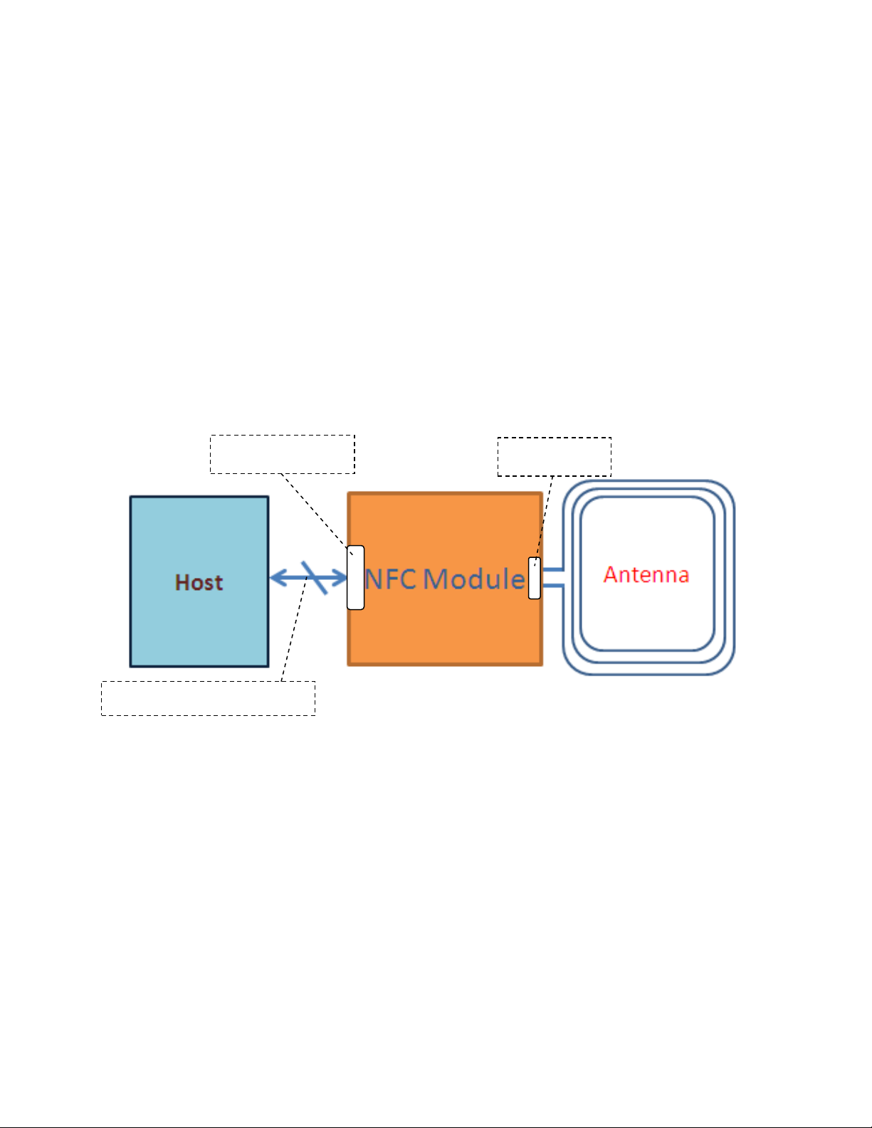
XRAV-1 is a kind of NFC (Near Field Communication) module that could be embedded in one IT
system by simply connecting the module through I2C interface and start developing his application
software.
2. Hardware Block Diagram
XRAV-1 is a full feature NFC module and compliant with NFC standards (NFC Forum, EMVCo,
ETSI/SCP). XRAV-1 has an optimized architecture for low-power consumption in different
operation modes. The RF contactless front-end is supporting various transmission modes according
to NFCIP-1, NFCIP-2, ISO/IEC14443, ISO/IEC 15693, ISO-14443, MIFARE, and FeliCa
specifications. The major internal components are illustrated in Figure 1-1.
Note:
• Host FPC/FFC Connector:
Allow user to connect the XRAV-1 module to the host board via FPC/FFC connector.
• Antenna Connector:
Connected to FPC antenna, please note that matching circuitry should be design on antenna.
NFC module Delivery Specification 1 V0.9
Figure 1-1 NFC module Major Component and System Interface (Assembly Guide)
Page 3
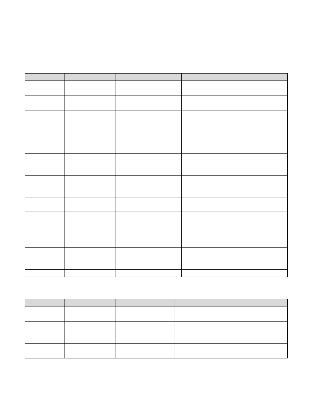
3. Pin Definition
Pin number
Name
Configuration
Description
1
MOD_VDD
Power Supply Input
Module power supply
2
MOD_GND
Power Supply Ground
Module ground
3
SWP
Input/ Output
Single Wire Protocol line to UICC/ SIM
4
MOD_VUP
Power Supply Input
Power supply for RF Front-end
5
IRQ
Output
Interrupt request from module to
platform
6
VDD_SIM
(PMUVCC)
Power supply input
The power rail used to power UICC/
SIM. Applicable in a system where NFC
module used SWP to communicate with
an UICC/SIM in the platform
7
I2C_SDA
Input/ Output
I2C data 8 I2C_SCL
Input
I2C clock
9
MOD_GND
Input
Used for extra GND for signal integrity
10
Reset/ WakeUp
Input
Reset pin input from the host to wake up
the device from standby and also to reset
the device
11
DWL_REQ
Input
Control pin to set the NPC300 in
firmware download mode
12
SWP_PWR
(SIM_VCC)
Power Supply Output
Power supply to UICC/ SIM or power
supply ‘request’ to PMIC. Applicable in
a system where NFC module uses SWP
to communicate with an UICC/ SIM in
the platform.
13
MOD_VDD
Power supply input
Additional pin for module power supply
to support higher current capacity
14
VDD_IO
Power supply input
Host IO reference voltage
15
MOD_GND
Power Supply Ground
Module ground
Pin number
Name
Configuration
Description
1
ANT1
Output
Connection for antenna load modulation #1
2
RXP
Input
Antenna reception path #1
3
TX1
Output
Antenna transmission line #1
4
GND
Ground
Antenna ground
5
TX2
Output
Antenna transmission line #2
6
RXN
Input
Antenna reception path #2
7
ANT2
Output
Connection for antenna load modulation #2
3.1 FPC/FFC connector type
Host connector
Antenna connector
NFC module Delivery Specification 2 V0.9
Page 4

3.2 SMT type
Pin number
Name
Configuration
Description
1
MOD_VUP
Power Supply Input
Power supply for RF Front-end
2
IRQ
Output
Interrupt request from module to
platform
3
VDD_SIM
(PMUVCC)
Power supply input
The power rail used to power UICC/
SIM. Applicable in a system where NFC
module used SWP to communicate with
an UICC/SIM in the platform
4
I2C_SDA
Input/ Output
I2C data 5 I2C_SCL
Input
I2C clock
6
Reset/ WakeUp
Input
Reset pin input from the host to wake up
the device from standby and also to reset
the device
7
DWL_REQ
Input
Control pin to set the NPC300 in
firmware download mode
8
VDD_IO
Power supply input
Host IO reference voltage
9
MOD_GND
Power Supply Ground
Module ground
10
MOD_GND
Power Supply Ground
Module ground
11
ANT1
Output
Connection for antenna load modulation
#1
12
RXP
Input
Antenna reception path #1
13
TX1
Output
Antenna transmission line #1
14
GND
Ground
Antenna ground
15
TX2
Output
Antenna transmission line #2
16
RXN
Input
Antenna reception path #2
17
ANT2
Output
Connection for antenna load modulation
#2
18
MOD_VDD
Power Supply Input
Module power supply
19
SWP
Input/ Output
Single Wire Protocol line to UICC/ SIM
NFC module Delivery Specification 3 V0.9
Page 5

4. Specification
Item
Standard specifications
Main chipset
NXP NPC300
Frequency
13.56MHz
NFC
Standards
ISO/IEC 14443A, ISO/IEC 14443B PCD
FeliCa PCD mode
Mifare PCD encryption mechanism
ISO/IEC 15693/ICODE VCD mode
NFC Forum tags
NFCIP-1/NFCIP-2 protocol
EMVCo 2.0.1 for PICC and PCD mode
NFC Forum Wave 1 and Wave 2
ETSI/SCP 102 613 and 102 622 for SWP/HCI
Host interface
NCI protocol interface according to NFC Forum NCI 1.0 standardization
I2C High-speed mode supported
I2C Address
0x29
Host
connector
15 pin FPC/FFC
Antenna
connector
7 pin FPC/FFC
Operation
temperature
-25 ~ 80o C
Storage
temperature
-25o ~ 125o C
Symbol
Parameter
Min
Typical
Maximum
Unit
MOD_VDD
Power supply input
2.7
3.3
5.5
V
MOD_VUP
Power supply input
2.7
3.3
5.5
VDD_IO
IO power supply
1.62
1.8
1.98
3.0
3.3
3.6
VDD_SIM
Power supply input
1.62
1.8
1.98
3.0
3.3
3.6
SWP_PWR[1]
Power supply for SWP
interface
1.62
1.8
1.98
Symbol
Min
Typical
Maximum
Unit
I
MOD_VDD
--
--
190
[1]
mA
I
VDD_IO
--
--
15
5. Electrical Characteristics
Recommended Operating conditions
[1] No VDD_SIM power supply input.
Current consumption characteristics
[1] MOD_VDD=3.3V
NFC module Delivery Specification 4 V0.9
Page 6

6. Recommended Operation Temperature
Supply voltage
AC mains
DC
Type of DC Source
Internal DC supply
External DC adapter
Battery
Operational Climatic
Tnom (20°C)
Tmax (80°C)
Tmin (-25°C)
NFC module Delivery Specification 5 V0.9
Page 7

7. Host Reference Circuit
7.1 No SIM Card used
7.2 SIM Card used on mother board
NFC module Delivery Specification 6 V0.9
Page 8

8. Certifications and Regulatory
Item
Feature
Description
14.1
FCC
RF: FCC part 15C
EMI: FCC part 15B
14.2
IC
RSS-210 ISSUE 8
RSS-GEN ISSUE 4
14.3
CE
RF: EN 302 291-1 V1.1.1, EN 302 291-2 V1.1.1
EN 300 330-1 V1.8.1, EN 300 330-2 V1.6.1
EMC: EN 301 489-1 V1.9.2, EN 301 489-3 V1.6.1
Safety: EN 60950-1:2006/A11:2009+A1:2010+A12:2011+A2:2013
14.4
NCC
RF: LP0002
EMI: CNS 13438
14.5
SAR
EN62311
General:
This modular approval is limited to OEM/Integrators installation only.
OEM integrators are responsible for ensuring that the end-user has no manual instructions to remove or
install module.
The end user manual shall include all required regulatory information/warning as show in this manual.
End Product Labeling (FCC)
When the module is installed in the host device, the FCC ID label must be visible through a window on
the final device or it must be visible when an access panel, door or cover is easily re-moved. If not, a
second label must be placed on the outside of the final device that contains the following text: “Contains
FCC ID: _NKR-XRAV1_________
The grantee's FCC ID can be used only when all FCC compliance requirements are met.
Required FCC Compliance Statement for Host Integration
To integrate this module into the host, the host manufacturer is responsible for the applicable FCC rules,
including the limits for a Class B digital device, pursuant to Part 15 of the FCC Rules.
In the user manual of the host device, the following statements are required to be included.
This device complies with part 15 of the FCC Rules. Operation is subject to the following two
conditions: (1) This device may not cause harmful interference, and (2) this device must accept any
interference received, including interference that may cause undesired operation.
NFC module Delivery Specification 7 V0.9
Page 9

This device has been tested and found to comply with the limits for a Class B digital device,
pursuant to Part 15 of the FCC Rules. These limits are designed to provide reasonable protection
against harmful interference in a residential installation. This equipment generates, uses and can
radiated radio frequency energy and, if not installed and used in accordance with the instructions,
may cause harmful interference to radio communications. However, there is no guarantee that
interference will not occur in a particular installation If this equipment does cause harmful
interference to radio or television reception, which can be determined by turning the equipment off
and on, the user is encouraged to try to correct the interference by one or more of the following
measures:
–Reorient or relocate the receiving antenna.
–Increase the separation between the equipment and receiver.
–Connect the equipment into an outlet on a circuit different from that to which the receiver is
connected.
–Consult the dealer or an experienced radio/TV technician for help.
Changes or modifications not expressly approved by the party responsible for compliance could
void the user‘s authority to operate the equipment.
This transmitter must not be co-located or operating in conjunction with any other antenna or
transmitter.
Module Integration Restriction:
This device is intended only for OEM integrators under the following conditions:
(1) The antenna must be installed such that 20 cm is maintained between the antenna and users,
(2) The transmitter module may not be co-located with any other transmitter or antenna.
(3) The Loop antenna was verified in the conformity testing. Radiated transmit power must be equal to
or lower than that specified in the FCC/IC Grant of Equipment Authorization for FCC ID: NKR-XRAV1
and IC: 4441A-XRAV1. A separate approval is required for all other antenna type, or higher gain
antenna.
In the event that these conditions cannot be met (for example certain laptop configurations or
co-location with another transmitter), then the FCC/IC authorization is no longer considered valid and
the FCC ID/IC ID cannot be used on the final product. In these circumstances, the OEM integrator will
be responsible for re-evaluating the end product (including the transmitter) and obtaining a separate
FCC/IC authorization.
NFC module Delivery Specification 8 V0.9
Page 10

Radiation Exposure Statement
1177
This equipment complies with FCC/IC radiation exposure limits set forth for an uncontrolled
environment. This equipment should be installed and operated with minimum distance 20 cm between
the radiator & your body.
R&TTE Regulation:
In all cases assessment of the final product must be met against the Essential requirements of the
R&TTE Directive Articles 3.1(a) and (b), safety and EMC respectively, as well as any relevant Article
3.3 requirements.
1. The Loop antenna (gain: N/A dBi) was verified in the conformity testing, and for compliance the
antenna shall not be modified. A separate approval is required for all other operating configurations,
including different antenna configurations.
2. If any other simultaneous transmission radio is installed in the host platform together with this module,
or above restrictions cannot be kept, a separate RF exposure assessment and CE equipment certification
is required.
CE RF Exposure Compliance
This device meets the EU requirements and the International Commission on Non-Ionizing Radiation
Protection (ICNIRP) on the limitation of exposure of the general public to electromagnetic fields by way
of health protection. To comply with the RF exposure requirements, this equipment must be operated in
a minimum of 20 cm separation distance to the user.
NFC module Delivery Specification 9 V0.9
Page 11

End Product Labeling (IC)
Labeling Requirements for the Host Device (Section 3.2, RSP-100, Issue 11, January 2016): The host
device shall be properly labeled to identify the module within the host device. The Industry Canada
certification label of a module shall be clearly visible at all times when installed in the host device,
otherwise the host device must be labeled to display the Industry Canada certification number of the
module, preceded by the words ―Contains transmitter module, or the word ―Contains, or similar
wording expressing the same meaning, as follows: "Contains transmitter module
IC:_4441A-XRAV1___.
Required IC Compliance Statement for Host Integration
To integrate this module into the host, the host manufacturer is responsible for the applicable Industry
Canada rules, including the limits for a Class B digital device, pursuant to ICES-003 of the Industry
Canada Rules
CAN ICES-3(B)/ NMB-3(B)
In the user manual of the host device, the following statements are required to be included.
This device complies with Industry Canada license-exempt RSS standard(s). Operation is subject to
the following two conditions:
(1) this device may not cause interference, and
(2) this device must accept any interference, including interference that may cause undesired
operation of the device.
Le présent appareil est conforme aux CNR d'Industrie Canada applicables aux appareils radio
exempts de licence. L'exploitation est autorisée aux deux conditions suivantes:
(1) l'appareil ne doit pas produire de brouillage, et
(2) l'utilisateur de l'appareil doit accepter tout brouillage radioélectrique subi, même si le
brouillage est susceptible d'en compromettre le fonctionnement."
IC Module Integration Restriction:
This module has been certified by Industry Canada as modular approval with the following restrictions:
1. The Loop antenna was verified in the conformity testing, and for compliance the antenna shall not be
modified. A separate approval is required for all other operating configurations, including different
antenna configurations.
2. If any other simultaneous transmission radio is installed in the host platform together with this
module, or above restrictions cannot be kept, a separate RF exposure assessment and IC equipment
certification is required.
NFC module Delivery Specification 10 V0.9
Page 12

NCC remind
低功率電波輻射性電機管理辦法
第十二條
經型式認證合格之低功率射頻電機,非經許可,公司商號或使用者均
不得擅自變更頻率加大功率或變更原設計之特性及功能
第十四條
低功率射頻電機之使用不得影響飛航安全及干擾合法通信;經發現有干
擾現象時,應立即停用,並改善至無干擾時方得繼續使用
前項合法通信,指依電信法規定作業之無線電通信
低功率射頻電機須忍受合法通信或工業科學及醫療用電波輻射性電機
設備之干擾
NFC module Delivery Specification 11 V0.9
Page 13

NCC logo location
NFC module Delivery Specification 12 V0.9
 Loading...