

Page 1
UMC-9628FHN Product Specification
Version
Change history
Date
0.1
Preliminary release
2018/10/15
UMC-9628FHN LGA-type LTE Module
User Manual
WistronNeWeb Corp.
啟碁科技股份有限公司
Revision History
CONFIDENTIAL
THIS DOCUMENT CONTAINS PROPRIETARY TECHNICAL INFORMATION, WHICH IS THE
PROPERTY OF THE WISTRON NEWEB CORPORATION AND SHALL NOT BE DISCLOSED TO OTHERS IN
WHOLE OR IN PART, REPRODUCED, COPIED, OR USED AS THE BASIS FOR DESIGN, MANUFACTURING,
OR SALE OF APPARATUS WITHOUT WRITTEN PERMISSION OF WISTRON NEWEB CORPORATION.
Page 1
Page 2
UMC-9628FHN Product Specification
C O NTENTS
A. Product Description .................................................................................................. 3
B. Main Features .......................................................................................................... 6
B.1 Application interface features .......................................................................................... 6
B.2 Packet mode features ...................................................................................................... 7
B.3 LTE features ...................................................................................................................... 7
B.4 Short Message Service (SMS) features ............................................................................. 7
B.5 RF Specification ................................................................................................................ 7
E. Mounting considerations ......................................................................................... 11
F. Mechanic Specifications .......................................................................................... 11
G. Package Specifications ............................................................................................ 14
H. Label Form .......................................................................................................... 16
I. Electrostatic discharge (ESD)..................................................................................... 16
Page 2
Page 3
UMC-9628FHN Product Specification
A. PRODUCT DESCRIPTION
© WistronNeWeb Corporation
THIS DOCUMENT AND THE INFORMATION CONTAINED HEREIN IS PROPRIETARY AND
IS THE EXCLUSIVE PROPERTY OF WNC AND SHALL NOT BE DISTRIBUTED,
REPRODUCED, OR DISCLOSED IN WHOLE OR IN PART WITHOUT PRIOR WRITTEN
PERMISSION FROM WNC.
LIMITATION OF LIABILITY
THIS DOCUMENT AND THE INFORMATION CONTAINED HEREIN IS PURELY FOR
DESIGN REFERENCE AND SUBJECT TO REVISION BY WNC AT ANY TIME. NOTHING IN
THIS DOCUMENT SHALL BE CONSTRUED AS GRANTING ANY WARRANTY OR RIGHT TO
USE THE MATERIAL CONTAINED HEREIN WITHOUT WNC’S PRIOR EXPRESS WRITTEN
CONSENT. WNC SHALL NOT BE LIABLE FOR ANY USE, APPLICATION OR
DEVELOPMENT DERIVED FROM THE MATERIAL WITHOUT SUCH PRIOR EXPRESS
WRITTEN CONSENT.
FCC Regulations:
This device complies with part 15 of theFCC Rules. Operation is subject to the following two
conditions: (1) This device maynot cause harmful interference, and (2) This device must
accept any interference received, including interference that maycause undesired operation.
This device has been tested and found to comply with the limits for a Class B digitaldevice,
pursuant to Part 15 of the FCC Rules. These limits are designed to provide reasonable
protection against harmful interference in a residential installation. This equipment
generates, uses and can radiated radio frequency energy and, if not installed and used in
accordance with the instructions, may cause harmful interference to radio communications.
However, there is no guarantee that interference will not occur in a particular installation If
this equipment does cause harmful interference to radio or television reception, which can
be determined by turning the equipment off and on, the user is encouraged to try to correct
the interference by one or more of the following measures:
-Reorient or relocate the receiving antenna.
-Increase the separation between the equipment and receiver.
-Connect the equipment into an outlet on a circuit different from that to which the receiver is
connected.
Page 3
Page 4

UMC-9628FHN Product Specification
-Consult the dealer or an experienced radio/TV technician for help.
Caution: Changes or modifications not expressly approved by the party responsible for
compliance could void the user‘s authority to operate the equipment.
End Product Labeling
The final end product must be labeled in a visible area with the following: “Contains FCC
ID:NKRUMC-9628FHN”. The grantee's FCC ID can be used only when all FCC compliance
requirements are met.
RF Exposure Information
This device is intended only for ODM/OEM integrators under the following conditions:
(1) The antenna must be installed suchmore than 26cm is maintained between the antenna and
users,
(2) The transmitter module may not be co-located with any other transmitter or antenna.
(3) To comply with FCC regulations limiting both maximum RF output power and human
exposure to RF radiation, the maximum antenna gain including cable loss in a mobile exposure
condition must not exceed:
Standalone Condition:
1.5dBi in 700 MHz Band
3.6dBi in 1700 MHz Band
IMPORTANT NOTE:
This module is intended for ODM/OEM integrator. The integrator is stillresponsible for the
FCC compliance requirement of the end product, whichintegrates this module.26cm
minimum distance has to be able to be maintained between the antennaand the users for the
host this module is integrated into. Undersuch configuration, the FCC radiation exposure
limits set forth for anpopulation/uncontrolled environment can be satisfied.
Any changes or modifications not expressly approved by themanufacturer could void the
user's authority to operate this equipment.
USERS MANUAL OF THE END PRODUCT:
In the users manual of the end product, the end user has to be informed tokeep at least 26cm
separation with the antenna while this end product isinstalled and operated. The end user
Page 4
Page 5
UMC-9628FHN Product Specification
has to be informed that the FCCradio-frequency exposure guidelines for an uncontrolled
environment can besatisfied. The end user has to also be informed that any changes
ormodifications not expressly approved by the manufacturer could void theuser's authority
to operate this equipment. If the size of the end product issmaller than 8x10cm, then
additional FCC part 15.19 statement is required tobe available in the users manual: This
device complies with Part 15 of FCCrules. Operation is subject to the following two
conditions: (1) this device maynot cause harmful interference and (2) this device must
accept anyinterference received, including interference that may causeundesired operation.
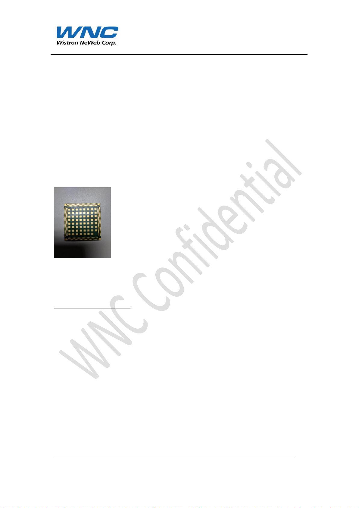
Figure1:UMC-9628FHNLGA-type LTEModule
A.1 General Descriptions
This document describes the specifications of UMC-9628FHN LGA LTE Module. This
moduleis based on Qualcomm MDM9628 platform and capable to allow users
enjoying high speed internet access anywhere and anytime over 4G LTE broadband
network.
With integrating UMC-9628FHN module, the end products are enhanced in both
functionality and usability based on leading edge mobile wireless technology.
This document will introduce hardware, software, mechanical and environmental
specifications in following sections.
Product information:
Page 5
Page 6
UMC-9628FHN Product Specification
Part Number
Category
WWAN
GNSS
Footprint
Dimension
UMC-9628FHN
CAT4
LTE 2/4/5/7/12/17
WCDMA 2/5
GSM 850/1900
GPS
LGA 263 pads
35x38x4.35(H ) mm
A.2 Applicable Device
The UMC-9628FHN is automotive grade LTE module with LGA pins and targeted for
automotive applicationthat is the Machine to Machine (M2M) market including TCU
(Telematics Control unit), AMM (Automatic Metering Management), tracking system,
etc.
B. MAIN FEATURES
Support 1.8/3.0VUSIM
Operation System (OS) Support - Linux (device driver)
Certification
FCC (in plan)
Operating AmbientTemperature
Operating : -30°C ~ +85°C
Normal range: -30°Cto +70°C (fully compliant with 3GPP)
Extended range: -40°C to +85°C (fully functional)
Storage : -40°C ~ +85°C
B. 1 A P PL ICA T ION INTERFA CE FEATURES
WNC MAL (Modem Abstraction Layer) Manager SDK for Linux
Page 6
Page 7

UMC-9628FHN Product Specification
E-UTRA
Operating Band
Uplink Frequency
UE Transmit
Downlink Frequency
UE Receive
Band 2
1850 MHz - 1910 MHz
1930 MHz - 1990 MHz
B. 2 P ACKET MODE FEAT URES
LTE data rates with category 4 (UMC-9628FHN)
150 Mbps DL with 20 MHz bandwidth
50 Mbps UL with 20 MHz bandwidth
B.3 LTE FEATU RE S
3GPP LTE Release 10
Bandwidth support 1.4 MHz, 3 MHz, 5 MHz, 10 MHz, 15 MHz and 20 MHz per
3GPP standard
VoLTE
IPv4 and IPv6 supported
LTE Rel-10 MDT with location information
B.4 SHORT MESSAGE SERVICE ( S MS ) FEA T URES
SMS over SGs
SMS over IMS
B.5RF SPECIFICAT ION
Cellular Frequency Band
Page 7
Page 8

UMC-9628FHN Product Specification
Band 4
1710 MHz - 1755 MHz
2110 MHz - 2155 MHz
Band 5
824 MHz - 849 MHz
869 MHz - 894 MHz
Band 7
2500 MHz - 2570 MHz
2620 MHz - 2690 MHz
Band 12
699 MHz - 716 MHz
729 MHz - 746 MHz
Band 17
704 MHz - 716 MHz
734 MHz - 746 MHz
WCDMA B2
1850 MHz - 1910 MHz
1930 MHz - 1990 MHz
WCDMA B5
824 MHz - 849 MHz
869 MHz - 894 MHz
GSM850
824 MHz - 849 MHz
869 MHz - 894 MHz
GSM1900
1850 MHz - 1910 MHz
1930 MHz - 1990 MHz
E-UTRA
Operating Band
Channel Bandwidth (CHBW)
1.4 MHz
3 MHz
5 MHz
10 MHz
15 MHz
20 MHz
Band 2
Yes
Yes
Yes
Yes
Yes
Yes
Band 4
Yes
Yes
Yes
Yes
Yes
Yes
Band 5
Yes
Yes
Yes
Yes
Band 7
Yes
Yes
Yes
Yes
Band 12
Yes
Yes
Yes
Yes
LTE Channel Bandwidth
Page 8
Page 9

UMC-9628FHN Product Specification
Band17
Yes
Yes
Specification
Min
Typ
Max
Units
LTE Sensitivity
B2 (1930-1990MHz Rx) - 10MHz
-101
-94.3
dBm
B4 (2110-2155MHz Rx) - 10MHz
-101
-96.3
dBm
B5 (869-894MHz Rx) - 10MHz
-101
-94.3
dBm
B7 (2620-2690MHz Rx) - 10MHz
-100
-94.3
dBm
B12 (729-746MHz Rx) - 10MHz
-103
-93.3
dBm
B17 (734-746MHz Rx) - 10MHz
-103
-93.3
dBm
UMTS Sensitivity
B2 (1930-1990MHz Rx)
-109
-104.7
dBm
B5(869-894MHz Rx)
-109
-104.7
dBm
GSM Sensitivity
GSM850 -109
-102
dBm
GSM1900
-109
-102
dBm
LTE Max Output Power
B2 (1850-1910MHz Tx)
20.3
23
25.7
dBm
B4 (1710-1755MHz Tx)
20.3
23
25.7
dBm
B5 (824-849MHz Tx)
20.3
23
25.7
dBm
B7 (2500-2570MHz Tx)
20.3
23
25.7
dBm
RF Performance
Page 9
Page 10

UMC-9628FHN Product Specification
B12 (699-716MHz Tx)
20.3
23
25.7
dBm
B17 (704-716MHz Tx)
20.3
23
25.7
dBm
UMTS Max Output Power
B2 (1850-1910MHz Tx)
20.3
23
25.7
dBm
B5 (824-849MHz Tx)
20.3
23
25.7
dBm
GSM Output Power
GSM850
31
33
35
dBm
GSM1900
28
30
32
dBm
EDGE Max Output power - multislot 1D4U MCS5 (Profile1)
GSM850
19
23
27
dBm
GSM1900
18
22
26
dBm
Sensitivity
-154dBm
Acquire First with Signal Level
-140dBm
Time To First Fix (TTFF) with -130 dBm
input signal
< 10s(Assisted)
< 60s (Non-Assisted)
2D RMS Accuracy with -130 dBm input
< 5 Meters
Note: The RF Transmit Specification is defined at the LGA pad.
GPS Receive Specifications
Page 10
Page 11

UMC-9628FHN Product Specification
Profile
Min.
Max.
Unit
Preheat time from140°C to 190°C
70
105
S
Time maintained above 230°C
40
60
S
Peak package body temperature
230
250
°C
Time maintained above 217°C
60
90
S
E. MOUNTING CONSIDERATIONS
Reflow soldering profile:
F. MECHANIC SPECIFICATIONS
Page 11
Page 12

UMC-9628FHN Product Specification
Figure 6 shows the top and bottom view of UMC-9628FHN and provides an overview
of the board's mechanical dimensions and further details information is shown as
Figure 7.
FIGURE 1: T OP AND BOTTOM VIEW OF UMC-9628
FIGURE 2: DIMENSIONS OF UMC-9628 (UNIT: MM)
Page 12
Page 13

UMC-9628FHN Product Specification
1.1.1 SMT PCB Assembly
The land pattern and stencil design as shown below is for lead-free solder paste and a
120 micron thick stencil.
FIGURE 3: LAND PATTERN OF UMC-9628 (TOP VIEW)
Page 13
Page 14

UMC-9628FHN Product Specification
FIGURE 4: RECOMMENDED STENCIL OF UMC-9628 (TOP VIEW)
G. PACKAGE SPECIFICATIONS
The single-feed tape carrier for UMC-9628FHN is illustrated in Figure 11. The figure
also shows the proper part orientation. The tape width is 56 mm and the module is
placed on the tape with a 44 mm pitch. The Direction into SMD machine is shown as
Page 14
Page 15

UMC-9628FHN Product Specification
Figure 12. The packing length per reel is 10.6 meters and each reel contains 150 pcs
modules.
FIGURE 5: CARRIER TAPE
Page 15
Page 16

UMC-9628FHN Product Specification
Specification/Requirements
Contact discharge
FIGURE 6: REEL DIRECTION
H. LABEL FORM
Dimension : 19mm * 19mm (example as shown below)
I. ELECTROSTATIC DISCHA RGE (ESD)
UMC-9628FHN module is not protected against Electrostatic Discharge (ESD) in
general. Consequently, it is subject to ESD handling precautions that typically apply to
ESD sensitive components. The remaining interfaces of UMC-9628FHN with the
exception of the antenna interfaceare only protected according to the
ANSI/ESDA/JEDEC JS-001-2011 requirements.
Page 16
Page 17

UMC-9628FHN Product Specification
Human Body Model
2KV
Charge Device Model (CDM)
500V
TABLE 6-3-1 ESD SPECIFICATION
Page 17
Page 18

UMC-9628FHN Product Specification
S
20 Park Avenue II,
Hsinchu Science Park,
Hsinchu 308, Taiwan, R.O.C.
TEL: 886-3-666-7799
FAX: 886-3-666-7321
Website: http://www.wnc.com.tw
Page 18
 Loading...