

Wistron NeWeb SWA9 User Manual
PRELIMINARY
AudioMagic™ Module Datasheet
General Description
Every consumer wants to be free from wires,
but it has been challenging to find a lo w-cost,
high-quality, easy-to-use wireless audio
solution for the wireless subwoofer market.
Avnera’s proprietary wireless system takes a
new approach to wireless audio. The wireless
protocol was designed from the ground up and
delivers uncompressed mono audio, with fixed
latency over the air, without interference
problems.
Avnera’s wireless modules offer a low-touch,
easy-to-integrate wireless audio solution and
enable fast time to market by already solving
the problem associated with FCC certification,
antenna tuning and board optimization.
Modules based on Avnera’s AV6600 silicon
provide breakthrough wireless audio
functionality with fixed low-latency point-topoint transport of uncompressed mono PCM
audio data at 16-bit, 48 kHz resolution using
either analog or digital (I2S) interfaces .
Applications
Wireless Subwoofers
Mono audio channel transmission
Mono Wireless Audio Systems, based on Avnera’s AV6600 IC
Point-to-point AVMD6600-SWA91 module family for
Features
Audio Interfaces
I2S Digital Input Interface with 95dB
end-to-end digital audio path
Integrated DAC supporting Analog
output with 90dB SNR and 20-20KHz
bandwidth (RXA model only)
Support for 15m range
Frequency range: 2.4 GHz ISM band,
continuous dynamic frequency selection
Forward error correction coding, error
detection, and audio-specific error
concealment
Dual onboard printed PCB antennas for
multipath and fading mitigation
Auto-search/synch and dynamic channel
selection
Low, fixed latency of 13ms, su itable for
video lip-synch
Connector: 2mm header which allows for
either horizontal or vertical module mounting
Sample rate converter: Support for 16, 20,
24, and 32 bit PCM words at 8,16, 22.05, 24,
32, 44.1, and 48 kHz
General purpose over-the-air (OTA) serial
interface:
2 kbps, bi-directional, full duplex
Ordering Options
AVMD6600-SWA91TXD: Transmit module
with digital audio input and integrated printed
PCB antennas
AVMD6600-SWA91RXD: Receive module
with digital audio output and integrated printed
PCB antennas
AVMD6600-SWA91RXA: Receive module with
analog audio output and integrated printed
PCB antennas
AVNERA CORPORATION | 16505 NW BETHANY COURT SUITE 100 | BEAVERTON, OREGON 97006, U.S.A. | MAIN +1.503.718.4100 | FAX +1.503.718.4101 | WWW.AVNERA.COM
AVNERA PROPRIETARY & CONFIDENTIAL | PROVIDED UNDER NDA
Support for meta-data and remote
control commands

AudioMagic AVMD6600-SWA91 Family Module Datasheet PRELIMINARY v0p1
1 Table of Contents
General Description ______________________________________________________________ 1
Applications ____________________________________________________________________ 1
Ordering Options ________________________________________________________________ 1
Features _______________________________________________________________________ 1
1 Table of Contents ____________________________________________________________ 2
2 Lists of Figures and Tables ____________________________________________________ 3
3 AVMD6600-SWA91-TXD/RXD/RXA Functional Block Diagrams _____________________ 4
4 AVMD6600-SWA91 Pin Information ____________________________________________ 7
5 AVMD6600-SWA91 Mechanical Dimensions______________________________________ 9
6 Electrical Specifications ______________________________________________________ 10
6.1 Absolute Maximum Ratings ___________________________ ____ _______________________________ 10
6.2 Recommended Operating Range __________________________________________________________ 10
6.3 Electrical Characteristics ________________________________________________________________ 11
7 Application information ______________________________________________________ 12
7.1 Mechanical requirements ________________________________________________________________ 12
7.2 Application circuit ______________________________________________________________________ 13
7.3 External I2S Requirement _______________________________________________________________ 13
8 FCC and Industry Canada certification information _______________________________ 14
8.1 Label Information ______________________________________________________________________ 14
8.2 Equipment labeling requirements _________________________________________________________ 14
8.3 User manual labeling requirements ________________________________________________________ 15
9 Ordering Information _______________________________________________________ 16
10 Contact Information and Legal Disclaimer _____________________________________ 17
CONTENTS SUBJECT TO CHANGE WITHOUT NOTICE 2 AVNERA PROPRIETARY & CONFIDENTIAL

AudioMagic AVMD6600-SWA91 Family Module Datasheet PRELIMINARY v0p1
2 Lists of Figures and Tables
Table 1: AVMD6600-SWA91 Module Block Diagram Description ___________________________________________ 6
Table 2: AVMD6600-SWA91 Pin Information ___________________________________________________________ 7
Table 3; AVMD6600-SWA91 Electrical Characteristics __________________________________________________ 11
Table 4: AVMD6600-SWA91 Module Ordering Information _______________________________________________ 16
Figure 1: AVMD6600-SWA91TXD Module Block Diagram................................................................................................ 4
Figure 2: AVMD6600-SWA91RXD Module Block Diagram ............................................................................................... 4
Figure 3: AVMD6600-SWA91RXA Module Block Diagram ..................................................................................... ........... 5
Figure 4: AVMD6600-SWA91 mechanical dimensions .............. .............................................. ...................................... ..... 9
CONTENTS SUBJECT TO CHANGE WITHOUT NOTICE 3 AVNERA PROPRIETARY & CONFIDENTIAL
AudioMagic AVMD6600-SWA91 Family Module Datasheet PRELIMINARY v0p1
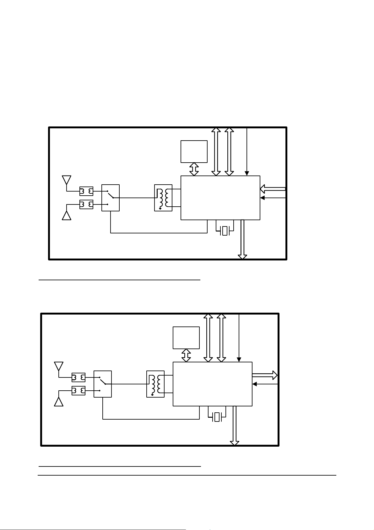
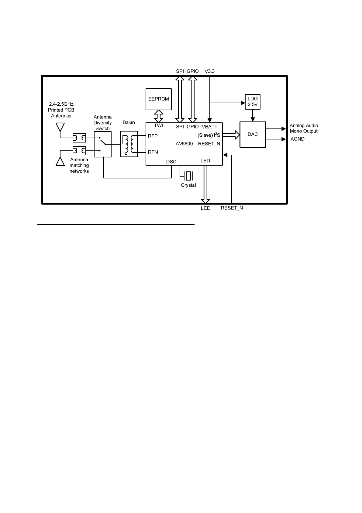
3 AVMD6600-SWA91-TXD/RXD/RXA Functional Block Diagrams
The AVMD6600-SWA91 module is available in three variations, Digital Input Transmitter, Digital Output
Receiver and Analog Output Receiver.
Note: The device does not have full I2S master capability and cannot generate MCLK as an output.
SPI
GPIO
V3.3
2.4-2.5GHz
Printed PCB
Antennas
Antenna
matching
networks
Antenna
Diversity
Switch
Balun
EEPROM
TWI
RFP
RFN
Figure 1: AVMD6600-SWA91TXD Module Block Diagram
DSC
SPI
SPI
GPIO VBATT
AV6600
Crystal
GPIO
(Slave) I2S
RESET_N RESET_N
LED
LED
V3.3
I2S Audio Input
2.4-2.5GHz
Printed PCB
Antennas
Antenna
matching
networks
Antenna
Diversity
Switch
Balun
EEPROM
TWI
RFP
RFN
DSC
SPI
GPIO VBATT
AV6600
Crystal
2
(Slave) I
RESET_N RESET_N
LED
LED
S
I2S Audio Output
Figure 2: AVMD6600-SWA91RXD Module Block Diagram
CONTENTS SUBJECT TO CHANGE WITHOUT NOTICE 4 AVNERA PROPRIETARY & CONFIDENTIAL
AudioMagic AVMD6600-SWA91 Family Module Datasheet PRELIMINARY v0p1
Figure 3: AVMD6600-SWA91RXA Module Block Diagram
CONTENTS SUBJECT TO CHANGE WITHOUT NOTICE 5 AVNERA PROPRIETARY & CONFIDENTIAL

AudioMagic AVMD6600-SWA91 Family Module Datasheet PRELIMINARY v0p1
Table 1: AVMD6600-SWA91 Module Block Diagram Description
Interface Description
SPI
GPIO/ LED
Analog Audio
RESET_N
V3.3
I2S
The AVMD6600s SPI interface is used to allow an external host to control the AV6600 IC
and to facilitate testing of the module.
The GPIO and LED lines allow buttons and LEDs to be connected to the AVMD6600SWA91 to allow the user to control the Audio Magic system and communicate the
system’s state to the user.
These pins form the AVMD6600-SWA91RXA module’s analog audio output. The analog
ground on the module and should be isolated from the host system’s ground to prevent
the creation of noise-inducing ground loops.
This pin connects directly to the “RESET_N” pin on the AV6600 IC and is used to signal
the module to power on and off.
This pin provides power to all elements of the AVMD6600-SWA91. Internal regulators
condition the input power according to the requirements of the various sub-circuit blocks.
These input pins connect to the AV6600’s digital audio interface and provide a digital
audio input channel. The AVMD6600-SWA91 TXD is always an I2S slave while the
AVMD6600-SWA91 RXD can be either a Slave or a Master I2S port but the module
cannot generate MCLK as an output..
Depending upon module configuration the audio data direction will change.
CONTENTS SUBJECT TO CHANGE WITHOUT NOTICE 6 AVNERA PROPRIETARY & CONFIDENTIAL
 Loading...