

Page 1

802.11g WLAN Router
SER’S GUIDE
U
ERSION 1.0, JUN. 2003
V
Page 2

802.11g Router User’s Guide
Copyright Statement
No part of this publication may be reproduced, stored in a retrieval system, or transmitted in
any form or by any mean s, whether electronic, m echanical, photoco pying, recording or
otherwise without the prior writing of the publisher.
Windows 95/98 and Windows 2000 are trademarks of Microsoft Corp.
Pentium is trademark of Intel.
All copyright is reserved.
1
Page 3

TABLE OF CONTENT
INTRODUCI NG THE 802. 11G ROUT ER.......................................................................................................................... ..........3
O
VERVIEW OF THE
802.11G ROUTER APPLICATIONS................................................................... ............................................. .................................4
A SECURITY OVERVIEW....................................... ........................................................... .......................................................... ...5
802.11G ROUTER FEATURES ................................................................... ............................................. ........................................5
SETTING UP THE DEVICE............ ............................................. ............................................ .........................................................6
INSTALLING THE 802.11G ROUTER.................. ............................................ ............................... ........................................7
W
HAT’S IN THE BOX
A
PHYSICAL LOOK AT THE BACK PANEL
A
PHYSICAL LOOK AT THE FRONT PANEL
CONNECTING THE CABLES ....................... ............................................. .......................................................... . ..........................10
HIGH LEVEL CONFIGURATION STEPS REQUIRE D FOR THE 802.11G ROUTER......................... ................................................10
SETTING UP A WINDOWS PC OR WIRELESS CLIENT AS DHCP CLIENTS......... ............................................ .............................11
CONFIGURING A PC RUNNING MS-WINDOWS 95/98/ME:.................. ............................................ .........................................11
CONFIGURING A PC RUNNING MS-WINDOWS XP/2000:........................................... ............................................. .................11
CONFIRMING YOUR PC’S IP CONFIGURATION:........................................ ............................................. ....................................12
CONNECTING MORE DEVICES THROUGH A HUB TO THE 802.11G ROUTER................... .......................................................12
BASIC CONFIGURATION OF THE 802.11G ROUTER........................ ... .... ... .. ..... .. .. ... .... ... .. ..... .. .. ... .... ... .. ..... .. ...............13
LOGGING ON............................... ............................................. ............................................ .......................................................14
SETUP WIZARD ........................... ........................................................... .......................................................... ...........................14
ADVANCED SETTINGS................................................................ .......................................................... ..................................22
O
PERATIONAL MODE
P
ASSWORD SETTINGS
S
YSTEM MANAGEMENT
SNMP S
ETTINGS
DHCP S
ERVER SETTINGS
MULTIPLE DMZ.................................... ........................................................................ ................ ........................................... ...29
VIRTUAL SERVER SETTINGS ....................................... ............................................. .......................................................... ........30
SPECIAL APPLICATIONS............................ ........................................................... ........................................................... ............31
MAC FILTERING SETTINGS ........................................ ............................................. .......................................................... ........32
IP FILTERING SETTINGS.................................. ............................................. ........................................................... ...................34
IP ROUTING SETTINGS .................................................. ............................................. .......................................................... ......36
WIRELESS SETTINGS...................................... ........................................................... .......................................................... ........37
RADIUS S
D
YNAMIC
MANAGING YOUR 802.11G ROUTER .......................................... ...................................................................................... .42
HOW TO VIEW THE DEVICE STATUS ..................................................... .......................................................... ...........................42
HOW TO VIEW THE SYSTEM LOG............................................ .......................................................... .........................................42
DHCP CLIENT TABLE ................... .......................................................... ............................................. ......................................43
WIRELESS CLIENT TABLE ........ ............................................ ............................................. .........................................................43
B
RIDGE TABLE
U
PGRADING FIRMWARE
H
OW TO SAVE OR RESTORE CONFIGURATION CHANGES
H
OW TO REBOOT YOUR
W
HAT IF YOU FORGOT THE PASSWORD
COMMAND LINE INTERFACE .......................................................... ........................................................... ........................46
GENERAL GUIDELINES............................................................. ............................................ .......................................................46
EXPRESS MODE VS. ADVANCED MODE OF OPERATION ...................... .......................................................... ...........................47
C
ONVENTIONS
C
OMMAND LIST
SPECIFICATION .................................................................. ....................................................................................... ...............49
802.11G R
?........................ ............................................. .......................................................... ....................................7
........................... .......................................................... ........................................................... .................22
........................... .......................................................... ........................................................... .................23
........................... ........................................................... ........................................................... ............24
........................... .......................................................... ........................................................... ........................26
........................... .......................................................... ........................................................... ..........27
........................... ........................................................... .......................................................... ....................38
ETTINGS
DNS S
............................ ........................................................... .......................................................... ...........................43
........................... ........................................................... .......................................................... .............................47
........................... .......................................................... ........................................................... ..........40
ETTINGS
........................... ........................................................... ........................................................... ............44
802.11G R
............................. .......................................................... ........................................................... ........................48
........................... ........................................................... ....................................................3
OUTER
............................ ........................................................... ...............................................8
............................ ........................................................... .............................................9
........................... .......................................................... ...........................................45
OUTER
? .................................................................... ............................................. .................45
........................... ........................................................... ...................44
2
Page 4

Federal Communication Commission Interference Statement
This equipment has been tested and found to comply with the limits for a Class B digital
device, pursuant to Part 15 of the FCC Rules. These limits are designed to provide
reasonable protection against harmful interference in a residential installation. This
equipment generates, uses and can radiate radio frequency energy and, if not installed
and used in accordance with the instructions, may cause harmful interference to radio
communications. However, there is no guarantee that interference will not occur in a
particular installation. If this equipment does cause harmful interference to radio or
television reception, which can be determined by turning the equipment off and on, the
user is encouraged to try to correct the interference by one of the following measures:
- Reorient or relocate the receiving antenna.
- Increase the separation between the equipment and receiver.
- Connect the equipment into an outlet on a circuit different from that to whi ch the receiver
is connected.
- Consult the dealer or an experienced radio/TV technician for help.
FCC Caution: To assure continued compliance, (example - use only shielded interface
cables when connecting to computer or peripheral devices) any changes or modifications
not expressly approved by the party responsible for compliance could void the user's
authority to operate this equipment.
This device complies with Part 15 of the FCC Rules. Operation is subject to the following
two conditions:
(1) This device may not cause harmful interference, and
(2) This device must accept any interference received, including interference that may
cause undesired operation.
IMPORTANT NOTE:
This equipment complies with FCC radiation exposure limits set forth for an
uncontrolled environment. This equipment should be installed and operated
with minimum distance 20cm between the radiator & your body.
This transmitter must not be co-located or operating in conjunction with any
other antenna or transmitter.
The user cannot use channel 12 & 13, or it will be a violation of the
sensitive restricted bands of 15.205.
Page 5

Introducing the 802.11g Router
Chapter
This manual gives a basic introduction to 802.11g Wireless Router. It provides
information to configure the 802.11g Router to operate in common applications
such as connecting to the Intern et.
We’ll describe how to use your web browser to configure the 802.11g Router and to perform various
management functi on s, e. g. upgr adi ng the sof tw ar e, or vi ewing the sy st em log , a ta sk th at can b e useful
in ongoing operations.
This manual consi sts of th e fol lowing ch apt ers and append ixes:
Chapter One, Introduction, summarizes feature s and cap abiliti es of th e 802.11g Rout er.
Chapter Two, Installing the 802.11g Router, gives steps you should follow to install the 802.11g Router
and configure your PCs.
Chapter Three, Configuring the 802.11g Router, describes how to log in to the Web Manager, the
browser screen, and steps needed to configure your 802.11g Router for specific applications. It gives
easy-to-follow instructions for quick Internet access and provides a guide to basic 802.11g Router
configuration.
Chapter Four, Advance d Configurat ion, pro vide s inform ati on on advanc ed rout er conf igur ation.
Chapter Five, Manag i ng y ou r 802.1 1g Ro ute r , explains other management features of the 802.11g Router.
1
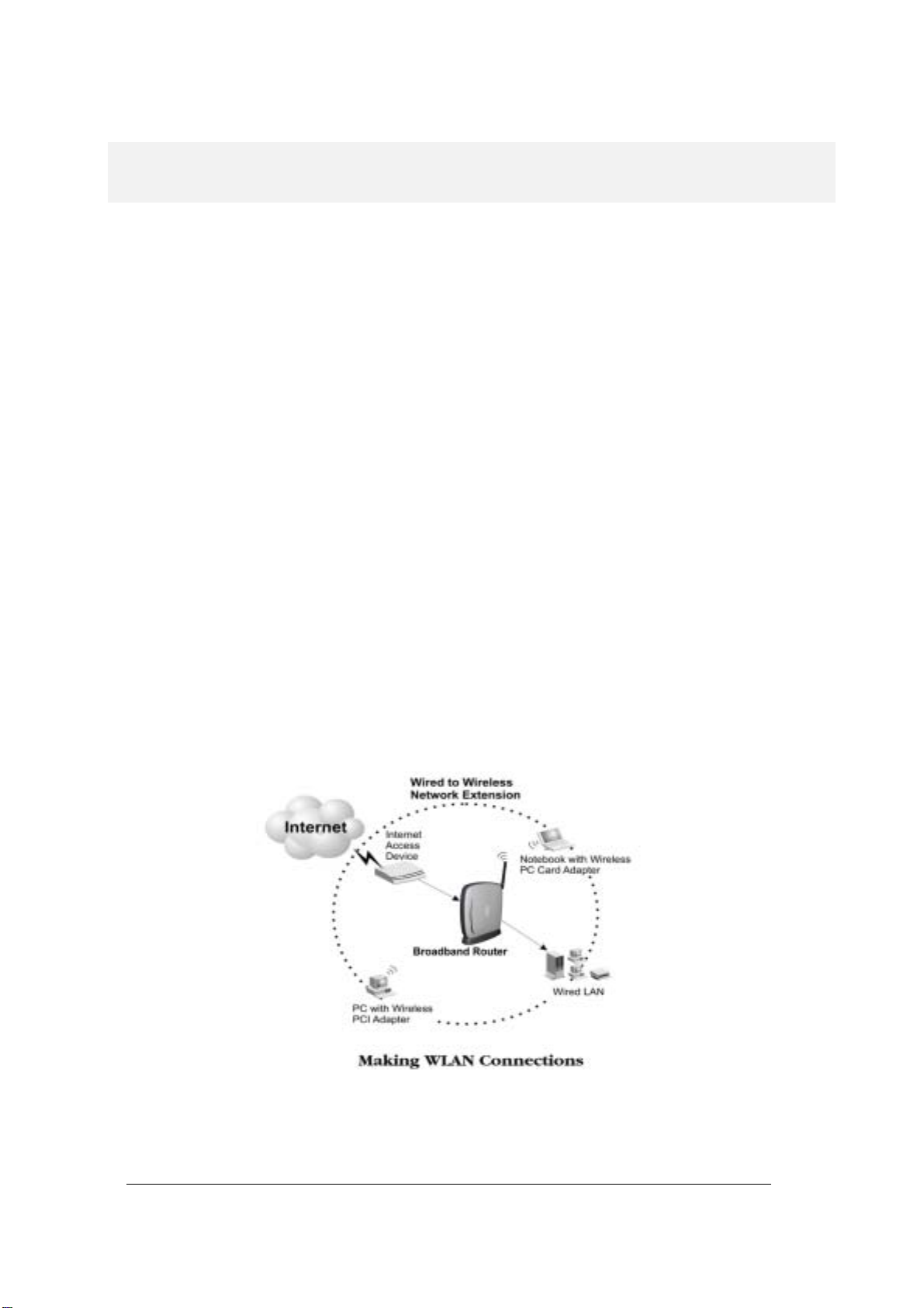
Overview of the 802.11g Router
The 802.11g Router is a small desktop router that sits between your local
Ethernet network and a remote network (e.g., the Internet). The 802.11g
Router contains an WAN port connecting to an external ADSL/Cable
modem, a DMZ port, a four-port 10/100Mbps Ethernet switch for
connection to PCs on your local wired net wor k, and a wireless interface fo r
connection to your local wireless network (supporting a data rate of up to
54 Mbps).
Data comes into the 802.11g Router from the local wired and wireless
LAN and then is “ro uted” t o the Int ernet , and vice ver sa.
Page 6
4
802.11g Router Applications
ACCESSING THE INTERNET
The most common use of the 802.11g Router is to provide shared Internet access to allow everyone
on your LAN to surf the web and send/receive emails or files. The 802.11g Router can automatically
acquire a public IP address when connecting to the Internet. In turn, it will automatically assign IP
addresses to PCs (requesting DHCP client devices) on your LAN - you don’t have to apply for and
assign IP addresses to PCs o n your net wor k.
ACCESSING SERVERS FROM THE PUBLIC NETWORK
If you want special ser vers t o be accessi ble to r emot e users ac ross th e Inter net ( e.g., an e- mail s erver , an
FTP server, or a web ser ver ) , you ca n co nf ig ure th e 80 2 .11g Rout er to pro xy the service using its (public)
IP address. It means a remote user can access the server by using the 802.11g Router’s IP address.
Upon receiving a r equ e st, t h e 802.1 1 g Rou t er wil l r e- dir ect th e r eq ue st t o th e ac tu a l ser ver o n yo ur l ocal
network.
OPERATING AS AN ACCESS POINT
Additionally, the Wireless Router can also be configured as an Access Point, and acts as the central
point of your local wir eless networ k suppo rting a d ata r ate of up to 54 Mbp s. It all ows client device s on
your wireless network to access the Internet, to communicate with other wireless devices on your
wireless network, or to com municate with d evices o n your wired LAN n etwork.
Since 802.11g is based on the same 2.4GHz radio band as the 802.11b technology, the 802.11g Router
can inter-operate with existing 11Mbps 802.11b devices. Therefore you can protect your existing
investment in 802. 11b cl ient cards, an d migrat e to th e high- speed 802.1 1g stan dar d as your ne eds gr ow.
Page 7

802.11g Router User’s Guide
A Security Overview
More and more people are concerned about protecting your local network from the Internet. The
802.11g Router prov ides s everal w ays to k eep you r networ k secur e:
Devices on your wired or wireless network are assigned private IP addresses; therefore remote
users from the In ternet c ann ot see no r acce ss th em.
The 802.11g Router implements IP packet filtering capabilities, which you can use to selectively
filter (discar d) packet s to /fr om the Int ernet .
You can selectively re strict manag ement to r emot e devi ces.
To address the gro wi ng se c ur ity conce rn in a wi rel ess LAN environment , di f fer ent l evel s o f secur it y
can also be enabl ed in the 8 02.11g Router, i nclu ding:
To disable SSID broadcast so to restrict association to only client stations that are already pre-
configured with correct SSIDs
To enable WEP (Wi rel es s Encr ypt ion Pr otoc ol ) encryption to i mplem en t pri va cy of y our dat a
Support of Access Control List to allow you to grant/deny access to/from specified wireless
stations (us ing M A C ad dr es se s)
Provisioning of central ized a uthent icati on throug h RA DIUS Ser ver(s).
802.11g Router Features
Compliant with 802.11b an d 802. 11g stan dard s with ro aming cap abi lity
Support of NAT for mult ipl e users t o shar e Inter net a ccess
IP routing (RIP1/RIP2) sup port
VPN (Virtual Private Net wor k) support for P PTP/ IPSec pa ss-t hrough.
Support of PP PoE and PPTP client fun cti on f or xDS L co nn ecti on s
Support of mult imed i a applications ( ICQ, N et Meet in g, CUS eeM e, Q u ick Time, etc) .
Support of the Vir tua l Serv er f unct ion.
Support of the stan dar d Ac ces s Point mo d e f or con ne ct ion to wir el e ss cl i ent s
Built-in DHCP server to assign IP addresses to DHCP client devices on both wired and
wireless LAN
Multiple security measures: to disable SSID broadcast, to define Access Control List, to
enable WEP based encryption (up to 128 bits), plus enhanced Security with 802.1x using a
primary and a backup RADI US Server
Extensive monitori ng cap abil ity such as event loggin g, t raff ic/erro r stati stic s monit orin g
5
Page 8

Easy configuration and monitoring through the use of a Web-browser based GUI, a
Command Line Interface (CLI) through a remote telnet session, or SNMP commands from a
remote SNMP management station
Setup Wizard for easy con figur ation/i nstal latio n
Setting Up the device
The 802.11g Router can be managed by a local PC on either the wired or wireless LAN network. To
do this, the 802.11g Router must have an IP address, which can be statically configured, or is
dynamically obt ained from a DHCP ser ver on the LA N. Fo r rea son s to b e g iven in Chapter 3 , st ati c I P
address assignm ent is mu ch pr efer red.
6
Page 9

802.11g Router User’s Guide
Installing the 802.11g Router
This section describes the installation procedure for your 802.11g Router. It starts
with a summary of the content of the package you have purchased, followed by steps of how to
connect and power up your 802.11g Router. Finally, it describes how to configure a Windows PC to
communicate with your 80 2.11g Rout er.
What’s in the Box?
The 802.11g Router packa ge com es with th e foll owin g items :
One 802.11g Router
One 12V AC power adapter wit h a bar rel conn ector
Chapter
2
One Category-5 LAN cable with RJ- 45 conne ctors
One copy of the 802.11g Rou ter Us er’ Guide
7
Page 10
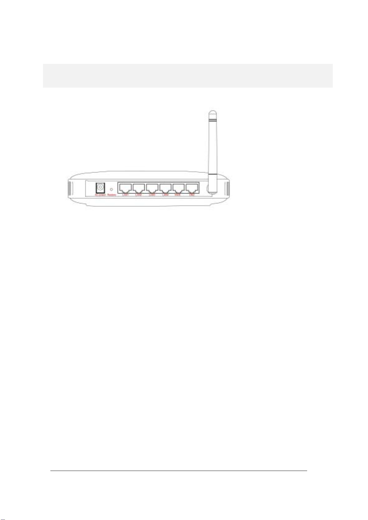
A physical look at the back panel
The following il lu stratio n s hows the rear panel of Wi reles s Rout er.
(1) 4 RJ-45 10/100 Switch connectors for connecting to PCs and workstations or connecting
external Ethern et hub, or s witch with auto-s ensing.
(2) 1 RJ-45 W AN co n nect or f or co nnect ing to Internet vi a AD SL/ Cab le modem
(3) 1 RJ-45 DMZ conne cto r for con nectin g to an inter nal DMZ n etwor k or a PC
(4) 1 AC power connector for connecting through an AC power adapter (included as part of the
product) to the w all po wer outlet
(5) 1 Restore button to restore the device back to the factory settings
8
Page 11
802.11g Router User’s Guide
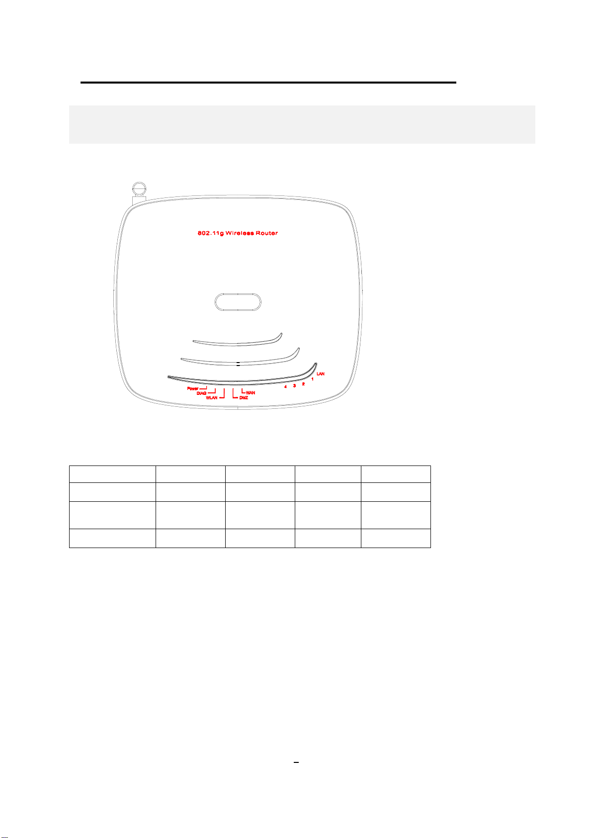
A physical look at the front panel
The LEDs on the fron t of th e 802.11g Router r eflect th e operatio nal statu s of the unit.
802.11g Router LED Description
Label LAN WAN/DMZ WLAN POWER
Steady Green Link is active Link is active Link is active Power
OFF
FLASH XMT/RCV Data XMT/RCV Data XMT/RCV Data N/A
No LAN
connection
No connection
No Wireless
connection
No Power
9
Page 12
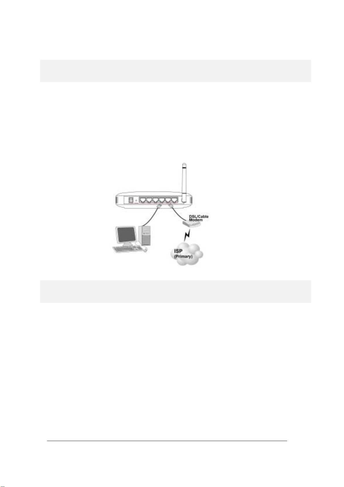
Connecting the Cables
Follow these st eps to install your 802. 11g Router :
Step 1 Connect ADSL/Cable modem to the Wireless Router WAN port using CAT5 UTP
LAN cable.
Step 2 Connect a PC/Workstation to one of the LAN ports of the Wireless Router, such as
port 1 or port 2.
Step 3 Connect the AC adapt er to t he Wirel ess Rout er and an ele ctri cal outl et .
High Level Configuration Steps Required for the 802.11g Router
This section describes configuration required for the 802.11g Router before it can work properly in
your network.
Normally, devices on both LANs (except for the Web servers) are configured to obtain their IP
addresses automat ica lly. De pendin g on wheth er ther e is a s epar ate DHC P server a vail able in your LAN
environment network, thus to determine if you need to enable the built-in DHCP server in the
Wireless Router. The following configuration step assumes that the route r’s built-in DHCPS will be
used.
Additionally, sin ce you need t o perfor m variou s configu ration chan ges to t he 802.11g Rout er, in cludi ng
the SSID, Channel number, the WEP key, …, etc., it is necessary to associate a fixed IP address with
the 802.11g Router, which is why the 802.11g Router will be shipped with a factory default private IP
address of 192.168. 1.1 (and a networ k ma sk of 255.25 5.2 55.0).
10
Page 13

802.11g Router User’s Guide
Setting up a Windows PC or wireless client as DHCP clients
The following will give detailed steps of how to configure a PC or a wireless client to “obtain IP
addresses automatically”. For other types of configuration, please refer to the corresponding user
manual.
For the case of using a LAN attached PC, the PC must have an Ethernet interface installed properly,
be connected to the 802.11g Router either directly or through an external LAN switch, and have
TCP/IP installed and configured to obtain an IP address automatically from a DHCP server in the
network.
For the case of using a wireless client, the client must also have a wireless interface installed properly,
be physically within the radio range of the 802.11g Router, and have TCP/IP installed and configured
to obtain an IP addr ess aut oma tica lly fro m a DHCP serv er in the n etwork.
Configuring a PC running MS-Windows 95/98/Me:
1. Click the Start Butt on, and select Set tings .
2. Click the Control Panel. The Win95/98/Me Control Panel will appear.
3. Open the Net work s et up w i ndow by dou ble- cl ick ing t he Net work icon.
4. Check your list of Net wor k item s. If TC P/IP is al read y instal led, pr ocee d to step 5. Oth erwis e:
(You may need your Windows CD to complete the installation of TCP/IP.)
Click the ADD button.
In the Network Component Type dialog box, select Protocol.
In the Select Networ k Pro tocol dialog box, select Micr oso ft.
In the Networ k Prot o co ls a rea o f the same dial o g b o x, select TCP/IP and cl ic k O K.
5. With TCP/IP inst alled , sele ct TCP/I P from t he li st of N etwork Comp onent s.
6. In the TCP/IP window, ch eck e ach of the tabs an d ver ify the f ollow ing sett ing s:
Bindings: Sele ct Client for Microsof t Network s and Fi les and print er shar ing for Micro soft
Networks
Gateway: All fields are blan k.
DNS Configuration: Select Disable DNS.
WINS Configuration: Selec t Use DHCP for WINS Reso lution.
IP address: Select th e Obtai n IP addr ess aut omat ically r adio butt on.
7. Reboot the PC.
Configuring a PC run ning MS- W indow s XP/ 2000:
1. Click the St ar t but to n, and ch oose Cont rol P anel ( in Cl assi c Vie w).
2. In the Control Panel, double-click Network Connections.
3. Double-click Local Area Connection.
4. In the LAN Area Connection Status window, select Internet Protocol (TCP/IP) and click
Properties.
5. Select the Obt a in an IP address au to ma ti ca lly and the Obt ain DN S ser ver addr e ss auto m ati cal ly
radio buttons.
11
Page 14
6. Click OK to finish the conf igurati on.
Confirming your PC’s IP Configuration:
There are two t ools useful f or fi nd ing ou t a computer's I P add re s s and d efau lt gateway:
WINIPCFG (for Windows 95/98/Me) Select the Start button, and choose Run. Type winipcfg, and a
window will appear li sting t he I P configur ation . You ca n also type winip cfg in the MS-DOS prompt .
The procedure required to set a static IP address is not too much different from the procedure
required to set to “obtain IP addresses dynamically” - except that at the end of step 7, instead of
selecting “obtain IP addresses dynamically, you should specify the IP address explicitly.
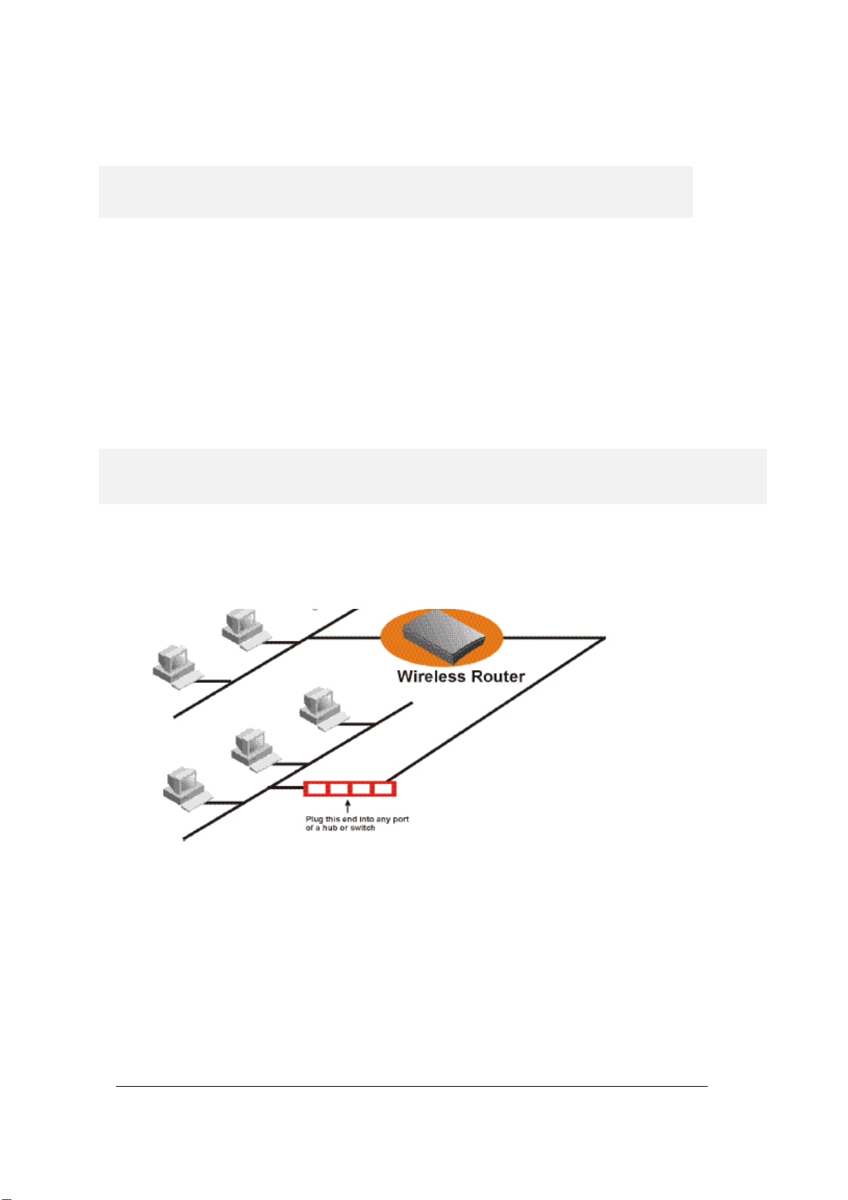
Connecting More Devices Through A Hub To The 802.11g Router
The Wireless Router provides four LAN ports to allow up to four PCs or Workstations to be
connected to it direct l y. If yo u want t o conn ect mor e d evic es, you can connect an external hub or
switch to any of the LAN p ort s using a LAN cable.
12
Page 15
802.11g Router User’s Guide
Basic Configuration of the 802.11g Router
This section contains basic configuration procedure for the 802.11g Router. It
describes how to set up the 802.11g Router for Internet Access operation, and how
to set up the LAN configur ation .
Although the Command Line Interface (CLI) may also be used to configure the 802.11g Router, the
browser-based configuration mechanism is generally preferred for its ease of use. The Internet
Explorer 6.0 and up are sup po rted .
The 802.11g Router is designed so that all basic configuration may be invoked through the a standard
Web browser such as Internet Expl orer.
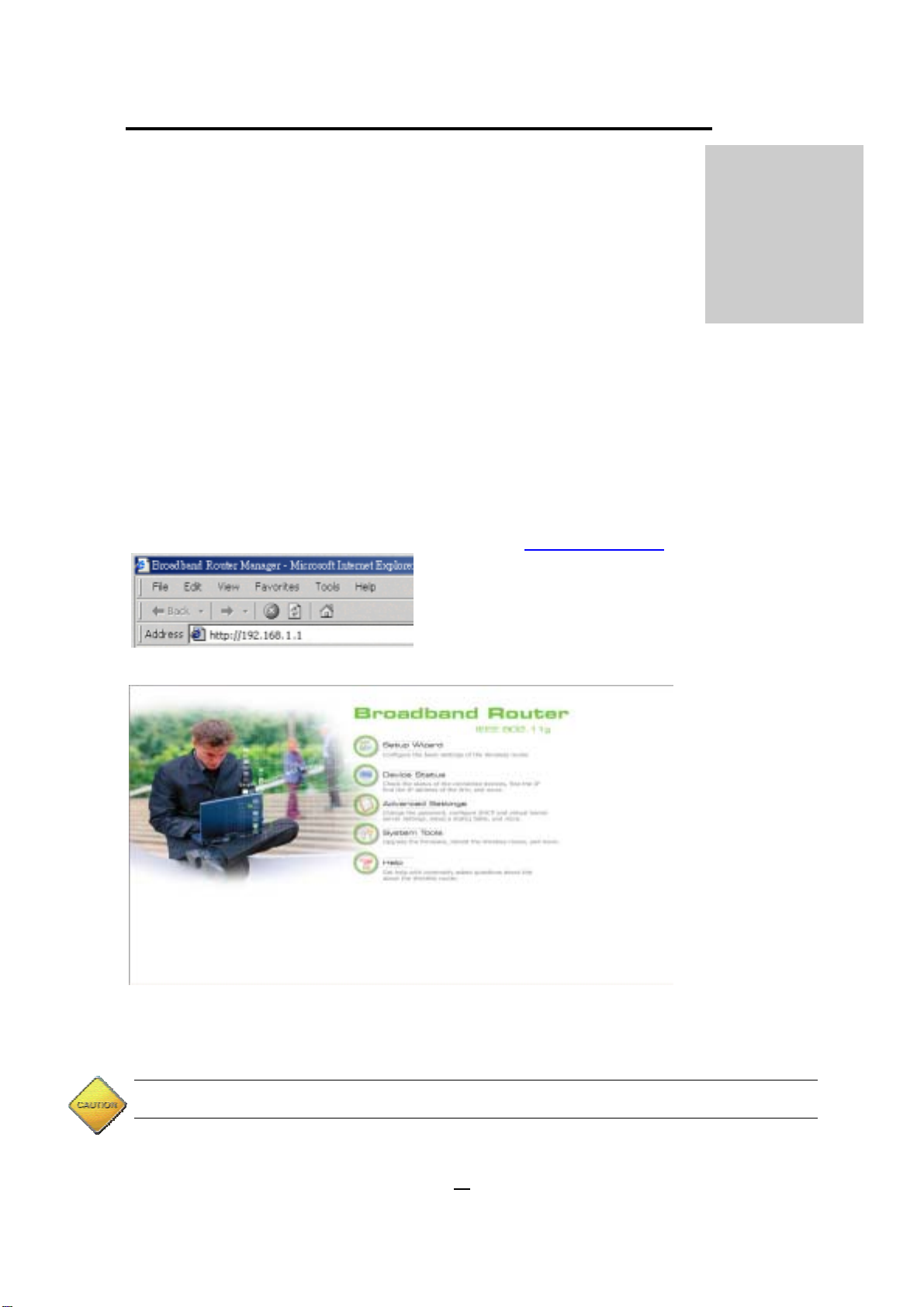
To access the WLAN 11g Router’s management interface for the first time, enter the default IP
address of the WLAN 11g Router in your Web browser http://192.168.1.1/
.
Chapter
3
Note: The IP address of your PC must be in the same IP subnet as the 802.11g Router. It is preferred that you
configure the PC to obtain an IP address auto matically from the 802.11g Rou ter.
13
Page 16
The Home Page of the 802.11g Router screen will appear, with its main menu displayed on the
screen, showing the following top-level choices: Setup Wizard, Device Status, System Tools,
Advanced Setting s, and Hel p. Sele cting any will allow y ou to navi gate to ot her con fi guratio n menus.
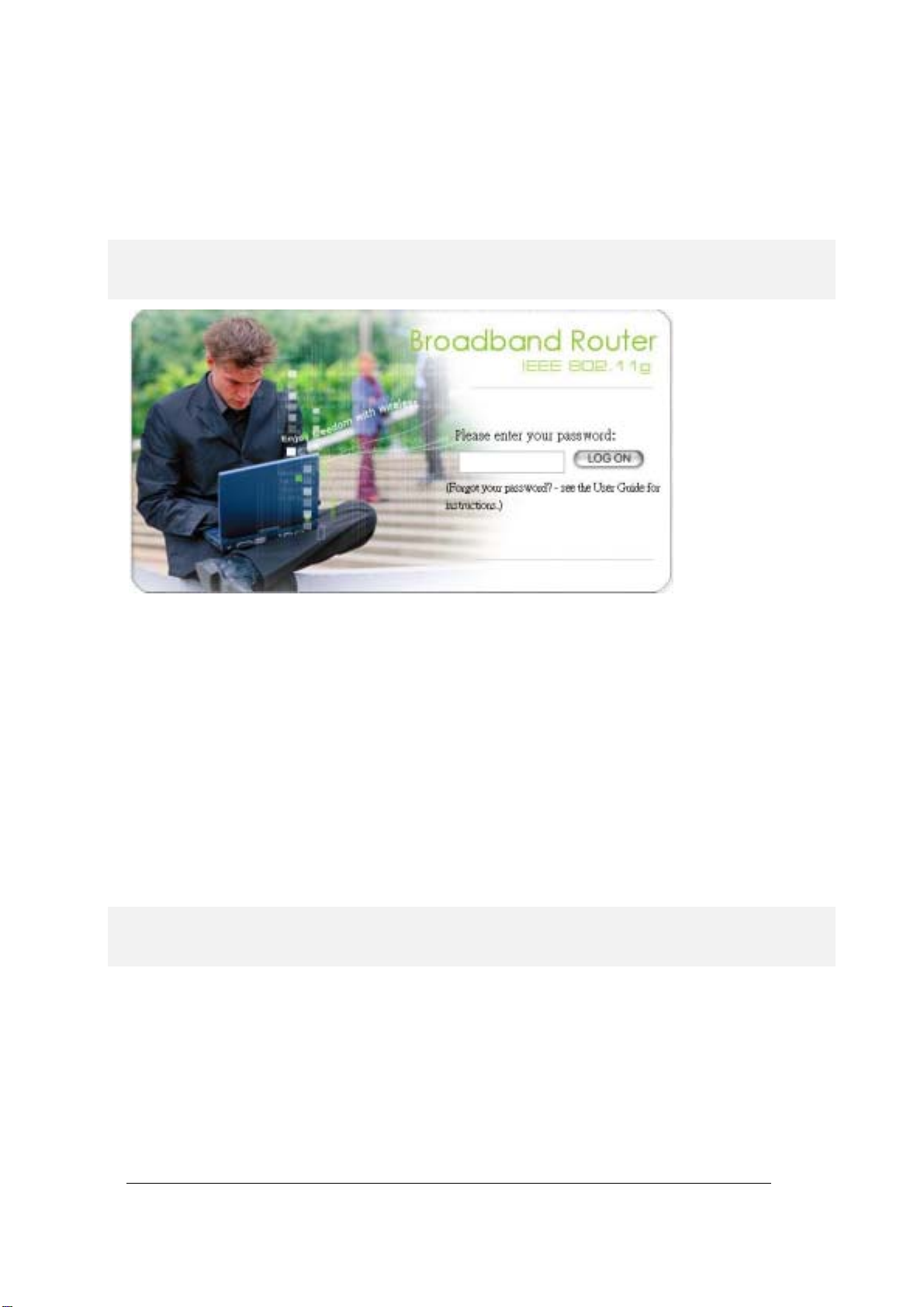
Logging On
When you attempt to access a configuration screen from the browser menu, an administrator login
screen will appear, prompting you to enter your password to log on. Once you are logged in, you will
not be asked to log in again unle ss you r “sessi on” expi res su ch as du e to in activ ity t imeout .
If you are logging in for the first time after you received your 802.11g Router, you should use the
factory default pa sswor d, “p assword” to lo g in. (Y ou shou ld ch ange it as soon as aft er you lo g in.)
Characters you type (as your password) will be echoed back as a string of asterisks (“*”) for security
reasons. After you enter the password, clicking the LOG ON button will begin the password
verification pr ocess and, if succ essful , your configu rati on sessi on c an begin.
Note: Should there be no settings or access on the web management screen, system will logout
automatically in 10 minutes.
Setup W iz a rd
The Setup Wizard will guide you through a series of configuration screens to set up the basic
configuration of your 802.11g Router. At the end of the Setup Wizard screens, you should press the
“finish” button, and all your configuration modifications will take effect.
SETTING UP YOUR LOCAL TIME ZONE AND DATE/TIME
After logging in, the Time Settings page appears. The router time will first be set to the local time of
the PC (on which the browser is running). If this time is not correct, modify the appropriate fields as
necessary, and th en cli ck “N EXT”.
14
Page 17

802.11g Router User’s Guide
DEVICE IP SETTINGS
The Device IP setting screen allows you to configure the IP address and subnet mask of your
802.11g Router: you can conf igur e a stati c IP addr ess an d a subnet mask, or conf igur e it to ob tain an I P
address and a subne t mask automat icall y from a DHCP s erver on th e loc al net work .
If you choose to assign a static IP address manually, check the button that says, “Assign static IP to
this device” and then f i ll i n t he fo llowi n g fi el ds
IP Address and IP Subnet Ma sk: These val ues def au lt to 192.1 68. 1.1 and 255.2 55. 255.0, r espect ively.
This IP address can be modified if necessary, to either a different address in this same subnet or to an
address in a differ ent subne t.
15
Page 18

When you modify it, if the DHCP server function of your 802.11g Router is enabled, the pool of
IP addresses it will use for assignment purpose s will also be automatcailly adjusted accord in gly. For
example, if the default IP address is used, the IP address pool for assignment consists of addresses
from 192.168.1.2 to 192.168.1.254. However, please do not change the default IP address unless
you know exactly what you wan t to achi eve.
Then you should press Next to get to the next screen.
If you choose to use an external DHCP Server to automatically assign an IP address to your 802.11g
Router, check the button that says, “Use the DHCP protocol to auto matica lly ge t the IP a ddress
for this device”, and then press Next to the next screen.
When an IP address is dynamically assigned to the router, its value can change depending on the IP
address assignment policy used by the DHCP server in the network. Since you need to use an IP
address to control and manage your 802.11g Router, without the knowledge of its IP address, in order
to access it, you will need to use UPnP (Universal Plug and Play) or other management tools that do
not depend on a fixed I P add ress.
It is strongly recom mend ed th at you sel ect the m anual stati c IP add res s.
CONFIGURE THE ISP PROFILE
In the following configuration screen, as with the usual convention, radio buttons are used to
make a selection when only one out of multiple mutually exclusive choices can be selected, while
square check boxe s can be used to select m u ltiple non-m utually-exclusive choices.
When configuring the device for Internet access, decide which one of the following multiple
choices to select (through radio buttons):
1. You can use a static IP ad dress provided by your ISP to connect to the Internet. In this c ase,
you need to configure the following information:
• IP Address Assigned by your ISP: the IP address of the WAN interface of your router.
• IP Subnet Mask: the IP subnet mask of t he WAN interface of your router.
• ISP Gateway IP Address: the I P add ress of your ISP’s Gateway.
•
DNS IP Address: the IP address of the DNS server .
2. You use the user name and password assigned by your ISP to connect to the Internet
(required for the underlying PPPoE protocol). In this case, you need to configure the
following infor m ation:
• User name: the username of your ISP account.
• Password: the passwor d of your ISP account.
• Idle time: The Idle Timeout is the number of seconds of "inactivity" before an
established PPPoE connection is taken down.
16
Page 19

802.11g Router User’s Guide
The idle time out val ue s hould be b etw een 0 t o 6 0 min ute s, w ith 5 (minu tes) being the de fau lt. A
value of 0 means the connection will never time out.
3. You use DHCP to connect to the Internet (most likely through a cable modem connection).
In this case, your ISP may require you to configure the Host Computer Name:
•
Host Name: The Host Name provided by your ISP.
4. You use PPTP to connect to the Internet. In this case, your ISP requires you to configure
PPTP's tunnel IP address, the username, and password. In this case, configure the static IP
address as in the above and then configure the following information:
• PPTP Local IP Address: the IP address on the local side of the PPTP tunnel provided
by your ISP.
• PPTP IP Netmask: the Netmask on the local side of the PPTP tunnel provided by your
ISP.
• PPTP Remote IP Address: the IP address of the remote side of the PPTP tunnel
provided by your ISP.
• User Name: the username of your ISP account.
• Password: the passwor d of your ISP account.
• Idle time: The Idle Timeout is the number of seconds of "inactivity" before the PPTP
connection is taken down.
Its value s ho u ld b e between 0 to 6 0 min ut es, with 5 (mi nut e s ) being the de fa ult value, a nd
0 meaning the connection will never time o ut.
Cloned MAC Address: Some ISPs expect a PC to be connected to their service, and use the MAC
address of this PC’s LAN card for identification purposes. By checking the following “Cloned MAC
address” square check box, your 802.11g Router allows a MAC address to be configured and
“cloned” in the router to simulate a PC.
If the device is a PC based on WIN 95/98/Me, you can run wi nipcfg to find out the MAC Address
of its LAN card. If the device is a PC based on WIN 2000/NT/XP, you need to run "ipconfig/all"
to find out the MAC address of it s LAN card.
17
Page 20

CONFIGURE YOUR WIRELESS LAN CONNECTION
In the following configuration screen, you can configur e wireless related para m eters of your
802.11g Router:
Network Name (SSID): The SSID is the network name used to identify a wireless network. The
SSID must be the same for all devices in the wireless network. Several Routers on a network can have
the same SSI D. The SSID can be u p to 30 ch arac ters long.
Disable SSID Broadcasting: An access point periodically broadcasts its SSID, along with other
information, which allows client stations to learn its existence while searching for Routers in the
wireless network. Select Disable if you do not want the device t o bro adcast th e S SID.
18
Page 21

802.11g Router User’s Guide
WLAN standard: You can select the device to run the 802.11g only protocol, or the mixed mo de –
allowing both 802.11g and 802.11b t o co-exist.
Regulatory Domain: You can select the regulat ory d omain wher e the de vice wil l be runnin g. Possib le
choices include FC C, ETSI , Fran ce, Spa in, and J apan.
Channel: Select the channel from the available list to match your network settings. All devices in the
wireless network must u se th e same ch ann el and sh are t he tota l band width availab l e.
Note: The availabl e channel numbers are different f ro m cou nt ry t o coun tr y.
USA and Canada: CH01~11, Europe: CH01~CH13, Japan: CH01~CH14, France: CH10~CH13,
Spain: CH01~CH13
You can use encryption t o pr otect your data wh en you are tran smit ting dat a in the wirel es s network.
You can select Disable WEP Key to disable encryption, or select one of four WEP keys to
transmit/receive data in the wireless network.
You can enter a “Passphrase” (a key of up to 30 alphanumerical characters), choose 40-bit, and press
the “Generate” button to generate four 40-bit keys in the entries below, or choose 128-bit, and press
the Generate button to gen erate on e 128- bit key i n th e first entry.
Alternatively yo u can m an u ally configure ea ch of t h em.
When you manually configure a key (an alphanumeric string), the length for a 40-bit WEP must be
equal to 5, and that for a 128-bit WEP key must be equal to 13. Once you enable the WEP function,
please make sure that exactly the same WEP key is configured in both the Wireless Router and client
stations.
You can define a key using ASCII or hex characters. A WEP128 ASCII key looks like "An ASCII
key!" (13 chara cters), while a WEP40 hex ke y look s like "44- 12-2 4-A8-B 2" (5 charact ers) .
Please note that som e Wir eless Cl ient Car ds all ow Hexad ecimal char acters on ly.
19
Page 22

FINISH SETUP WIZARD AND SAVE YOUR SETTINGS
After stepping th rough the Wizar d’s pag es, you c an pre ss the FINISH button for your modif ication t o
take effect. This wil l al so ca use your new settin gs to be saved in to yo ur syst em per manen tly .
20
Page 23

802.11g Router User’s Guide
Alternatively, You can also click the “Back” button to go back to previous configuration screens for
more changes.
Note: If you change the router’s IP address to a different IP network address space, as soon as you click on
FINISH you will no longer be able to communicate with your 802.11g Router. You need to change your IP
address and then re-boot your computer in order to resume the communication.
21
Page 24

Chapter
4
Advanced Settings
This secti on contains advanc ed setting pr ocedures for the 8 02.11g Router. It describes modifi cations
that normally you may not need for basic system operation. One exception i s changing your password:
it is highly recommended that you change the default factory setting as soon as you start to use your
802.11g Router.
Operational Mode
Before you start to use the device, you need to select the operational mode to be wireless AP only
or both Internet gateway and wireless AP:
Wireless Access Point only: When this is selected, the router operates in the AP-only
Mode, and connects Wireless Client Users to the Ethernet (WAN).
Internet Gateway + Wire less Access Point: When this is selected, the router will function
as an Internet acce ss sharing device as w ell as a wireless AP.
22
Page 25

802.11g Router User’s Guide
Password Settings
You r 802.11g Router c o mes with a d e fau lt f actory password o f “p asswor d”. After you start using the
router, you should change the default password.
To change the password, p ress th e Password Settings button to enter the Password Settings screen,
enter the current password followed by the new password twice. The entered characters will appear as
asterisks.
If you forgot the password, the only way to recover it is to return the device to its default state as
shipped from the factory. To restore the password to the default password, please refer to the
section, "What if I forgot the Password?" in the user manual.
23
Page 26

System Management
Clicking the System Manage ment button al lows sys tem relate d paramet ers to be co nfigured fo r the
802.11g Router.
Remote Management: The remote management feature allows you to manage your 802.11g Router
remotely through th e u se of an HTTP brow ser, or a tel net ut ility .
The system allows you to (1) allow remote management from all WAN IP addresses, to (2) allow
remote management from up to two WAN IP addresses, or to (3) disallow remote
management from any WAN IP addresses.
System Administration: The router allows you to designate special port numbers other than the
standard 80 and 23, respectively, for http or telnet for remote management. It also allows you to
specify the duration of idle time (inactivity) before a web browser or telnet session times out. The
default time-out va lu e is 10 mi nutes.
UPnP: The router's Universal Plug and Play (UPnP) feature allows a Windows XP/ME PC to
discover the router and automatically show an icon on its screen. You can double-click the icon to
access the router dir ectly (w ith out havin g to sp ecify its I P addre ss).
Disable Ping: "Ping" is a utility for testing the connectivity. Response to a ping can be disabled, such
as when you do not want t he router to be acc essed (e.g ., atta cked) fro m the Inter net.
24
Page 27

802.11g Router User’s Guide
Syslog: Syslog is an IETF (Internet Engineering Task Force - the Internet standards body)conformant standard for logging system events (RFC-3164). When the 802.11g Router encounters an
error or warning condition (e.g., a log-in attempt with an invalid password), it will create a log in the
system log table. To be able to remotely view such system log events, you need to check the Enable
Syslog box, configure the IP address of a PC where a Syslog daemon is running in the background.
When doing so, the 802.11g Router will send logged events over the network to the PC for future
viewing.
Syslog server IP addres s: The I P addre ss of the PC wher e the Sysl og daem on is r unning.
25
Page 28

SNMP Se tti ngs
This screen allows you to configure SNMP parameters including the system name, the location and
contact information. Additionally, you can configure the 802.11g Router to send SNMP Traps to
remote SNMP management statio ns. Traps are unsolicited alert messages th at 802.11g Router sends to
remote management stations.
System Name: A name that you assign to your 802.11g Router. It is an alphanumeric string of up to
30 characters.
System Location: Description of where your 802.11g Router is physically located. It is an
alphanumeric str ing of up t o 60 ch aracter s.
System Contact: Contact information for the system administrator responsible for managing your
802.11g Router. It i s a n alp h anumer i c st r ing o f up to 60 char act er s.
26
Page 29

802.11g Router User’s Guide
Community String For Read: If you intend the router to be managed from a remote SNMP
management station, you need to configure a read-only “community string” for read-only operation.
The community strin g is a n alphan umeri c str ing of up t o 15 char acter s.
Community String For Write: For read-write operation, you need to configure a write “community
string”.
A trap manager is a remote SNMP management station where special SNMP trap messages are
generated (by the router) and sent to in the network.
You can define trap manager s in th e system .
You can add a trap manager by entering a name, an IP address, followed by pressing the ADD
button.
You can delete a trap manager by selecting the corresponding entry and press the DELETE
SELECTED button.
You enable a trap manager by checking the En ab le box in the corresponding entry or disable the trap
manager by un-ch e
cking the Enable box.
DHCP Server Sett ings
The DHCP server option allows the
on your wired or wirel ess L AN to obtai n IP addr esse s auto matical ly.
If you want the Router to act as a DHCP server and assign private IP addresses to requesting
DHCP clients on the LAN, you need to check the Enable DHCP Server box.
You can select one of the following two ways to assign IP addresses:
Assigns IP addresses to wired or wireless clie nts from the following range:
When IP addresses are assigned to a requesting DHCP client, after the “lease time”, the
client is expected to renew the lease. Its default value is 10080 minutes.
The from and to range of IP addresses to be assigned to requesting DHCP clients can be
configured manually, with the default being 2 to 254.
After you enter the information, yo u should press APPLY.
Assigns the fol lowing IP address to the client with the followin g MAC address:
You can also specify the IP address to be assigned to a device with a pre-configured MAC
address.
802.11g Router
to assign IP addresses to DHCP client devices
You can add such a mapping by entering a MAC address, and the IP address to be assigned,
followed by pressing the ADD button. Up to 20 mappings can be added.
27
Page 30

You can delete a mapping by selecting the corresponding entry and press the DELETE
SELECTED button.
DHCP Table: Press this button will cause the screen to jump to DHCP client table page.
28
Page 31

802.11g Router User’s Guide
Multi pl e D MZ
The router s upports one hardwa re DMZ port, multiple softw are DMZ ports, plus one default
DMZ port.
The hardware DMZ is implemented throu gh the hardware: the rou ter has a separate hardwa re
Ethernet port, to which multiple devices with public IP addresses assigned by the ISP can be
connected. Incoming data for these devices from the Internet will be sent by the router to the
hardware Ethernet port directly. No configuration would be required.
Both the default and mul tiple DMZ ports are implemented through software.
When the router receives incoming data from the Internet, it will search through an internal
address translation table to perform address translation function. If a match cannot be found, the
data will be forwar ded to a special device for processing.
An additional feature is to allow devices with WAN IP addresses to be used by the Internet users
to access private devices in your local LAN. In this case, you need to configure the mapping
between the WAN IP address and the private IP address.
To add the default DMZ, you need to select “Default DMZ” and enter the local DMZ IP
address, followed by pressing the ADD button.
To add a device for multiple DMZ, first select “Multiple DMZ”, add a name, a public WAN
IP address , and the local DMZ IP address on the LAN, followed by pressing the ADD button.
You can delete a DMZ entry by selecting the corresponding entry and press the DELETE
SELECTED button.
29
Page 32

Virtual Server Settings
A Virtual Server is a server built on a single or a cluster of real servers. A DMZ server is a term
commonly used to describe the default Virtual Server - the router will redirect all traffic from the
Internet witho ut a vali d port addres s mapping to th is device . An HTTP se rver with a p rivate IP
address on the LAN allows access from the Internet by mapping a special port to the HTTP
server. In this case , th e HTTP service will be mapped to a port of the Rout e r.
You can add a virtual server mapping by (1) selecting the service name (such as HTTP, FTP,
TELNET, SMTP, POP3, CUSTOM), (2) enter the public port number to be used (either a
single port number or a range), (3) enter t he local IP address of the server on your LAN, (4)
enter its local port number to map to (either a single port number or the starting port number
of a range), (5) followed by pressing th e ADD button.
You can delete a mapping by selecting the corresponding entry and press the DELETE
SELECTED button.
Note: Virtual Server Setting and IP Filtering may affect with each other.
30
Page 33

802.11g Router User’s Guide
Special Applications
Special applications such as the Microsoft instant messaging or some Internet games are getting
to be increasingl y popular. These appli cations usuall y work in the following manner:
A client can start an Inte rnet ga me by firs t registe ring with a game serv er on the Inte rnet. Oth er
clients can, using the corresponding protocol, join the game by checking with the server and
deciding if to join t h e game. A client can "leave" the game at any time.
If the initiating client is behind your router, you need to add the application by performing the
following con fig u ra tion:
Select an application: Select an application that you want to add to the supported list. You
should choose "Other" if your application is not explicitly shown in the list.
Name: You can provide a name.
31
Page 34

Trigger Port: You need to specify, based on instructions provided by your application’s user
manual, the (UDP/TCP) port number in the router that the initiating client uses to start an
Internet game.
Trigger Type: Select UDP, TCP, or both for the trigger port.
Opened ports: You need to specify the port numbers in the router that joining clients can use to
communicate with the initiating client, again based on instructions provided by your application
user manual.
Public Type: Select UDP, TCP, or both for th e Opened ports.
After you finish the above, you press the ADD button to add an entry to the table.
You can delete an entry by selecting the corresponding entry and press the DELETE
SELECTED button.
MAC Filtering Settings
32
Page 35

802.11g Router User’s Guide
802.11g Router
The
allows you to define a list of MAC addresses. One of three mutually
exclusive rules c an be selected to forward/filter d ata packets based on th ese MAC addresses.
Disable MAC address control list: When this radio button is selected, no MAC address
filtering will be performed.
Enable GRANT address control list: When this radio button is selected, only packets
received from the wireless LAN interface with the configured MAC addresses will be
allowed/forwarded.
Enable DENY address control list: When this radio button is selected, only packets
received from the wireless LAN interface with the configured MAC addresses will be
denied/filtered.
Once a choice is made, the choice applies to all filtering rules.
To add a filtering rule, configure the following:
Mnemonic Name: the name to identify th e filter
MAC Address: the MAC address for grant or deny.
After you finish the above, you press the ADD button to add the ent r y to the table. There are up
to 32 MAC filtering rul es co uld be conf igured.
You can delete an entry by selecting the corresponding entry and press the DELETE
SELECTED button.
33
Page 36

IP Filtering Settings
Three mutually exclusive rules can be defined to forward/filter IP packets based on their IP
address and / or po rt numbers.
Disable IP filtering: If this is selected, the IP filtering feature is disabled. No IP filtering
will be performed.
GRANT IP access: When this is elected, p ackets received from/transmitted to WAN with
specified (source or destination) IP addresses will be allowed/forwarded.
DENY IP access: Packets receiv ed from/transmitted to WAN with the sp ecified IP
addresse s wi ll be denied/filtere d .
Once a choice is made, the choice applies to all filtering rules.
To define/add an IP filtering rule, ent er the following i nformation
• Name: The name of the filter
• IP Protocol: TCP or UD P
• Apply to: You need to sel ect whether the filter ing rule should apply to packets outbound
for the Internet or inbound from the Internet.
•
Source IP address: you can select Any, Single IP, or a Network (of source IP
addresses).
• Source Port: yo u can select Any, Single, or a Range of port numbers.
• Destination IP address: Any, Single IP, or a Network (of destination IP addresses).
• Destination Port: you can select Any, Single, or a Range of port numbers.
After you finish the above, you press the ADD button to add the entry to the tab le. There are up
to 32 IP filtering rules could be configured.
You can delete an entr y by selecting the corresponding entry and press the DELETE
SELECTED button.
Please Note that IP filtering is a sophisticated feature that can severely i mpact your Router
operation. Please be sure that you fully understand it before you use this feature. If you make any
mistakes, it can produce dramat ic and potentially undesirable result s.
34
Page 37

802.11g Router User’s Guide
35
Page 38

IP Routing Settings
Dynamic Routing: enable g ateway to c hange t he ro utin g table dyn amic ally th rough LAN por t.
Static Routing:
If you have routers on your LAN or WAN, you can configure static routes on the
802.11g Router to route network traffic to a specific, predefined destination. The 802.11g Router
can route packets based only on the packet's destination not on the source of a packet. Static
routes must be defined if the LAN or WAN are segmented into subnets. For example, a subnet
can be created to isolate a section of a company, such as finance, from traffic on the rest of the
LAN or WAN.
Static Routes are configured when network traffic is directed to a specific destination on the network
whether it is the LAN or WAN. For instance, you can configure the 802.11g Router to route
traffic from a computer, 192.168.1.100, on the LAN to a specific computer on the LAN,
192.168.168.2 7 usi n g the f o llo wing st ep s:
1. Enter the IP address of the de stinat ion net work in the Dest inati on Net work fi eld.
2. Enter the subnet in the Subnet Mask field.
3. Enter the IP address of th e default gatewa y in th e Defaul t Gat eway fiel d.
4. Select LAN from the In terf ace menu .
6. Click Add.
IP Routing Table: The Routing Tab le shows a lis t of des tina tions that the IP softwa re ma intai ns on
each host and router. The destinati on network IP address, subnet mask, gateway address, and the
corresponding de stin atio n link ar e displ ayed.
Note! The 802.11g Router can support up to 128 st atic rout e entrie s.
36
Page 39

802.11g Router User’s Guide
Wireless Settings
You can use this screen to conf igure var ious param eter s of your 802 .11g Rout er.
Beacon Interval: The 802.11g Router broadcasts beacon frames regularly to announce its existence.
The beacon Interval specifies how often beacon frames are transmitted - in time unit of milliseconds.
Its default value is 10 0; a va lid valu e shoul d be betwe en 1 and 10 00.
RTS Threshold: RTS/CTS frames are used to gain control of the medium for transmis sion. Any
unicast (data or control) frames larger than specified RTS threshold must be transmitted following the
RTS/CTS handshake exchange mechanism. The RTS threshold should have a value between 256-
37
Page 40

2432 bytes, with a default value of 2432. A value of zero activates the RTS/CTS handshake before
every transmiss ion. It is rec ommende d that t his val ue does not devi ate fr om the d efault too muc h.
Fragmentation: When the size of a unica st frame exceeds the fragmentation thr eshold, the frame wil l
be fragmented before transmission. The threshold should have a value of 256-2346 bytes, with a
default value of 2346. If you experience a high packet error rate, you should slightly decrease the
Fragmentation Threshol d.
DTIM Interval: The 802.11g Router buffers packets for stations that operate in the power-saving
mode. A Delivery Traffic Indication Message (DTIM) contains information on which powerconserving stations have packets waiting to be received. The DTIM interval specifies how often
beacon frames should contain DTIMs. It should have a value between 1 and 65535, with a default
value of 3.
RADIUS Settings
RADIUS (Remote Access Dial In Service) servers provide centralized authentication services to
wireless clients. Up to two RADIUS servers can be defined, one acting as a primary, and the other
acting as a backup .
Enable Primary Server: To configure the primary server, check the “Enable Primary Server” box,
and configure the f ollowi ng param eters:
Authenticate: Two user authentication methods can be enabled: one based on MAC address f ilt er , th e
other based on 802.1 x EAP/MD 5. You can s ele ct eith er or both .
38
Page 41

802.11g Router User’s Guide
MAC address filtering based authentication requires a MAC address filter table to be created in
either the 802.11g Router and/or the RADIUS server. During the Authentication phase, the
MAC address filter table is searched for a match against the wireless client’s MAC add ress to
determine whet her the st ati on is to b e allowed or deni ed t o acces s the netw ork.
The RADIUS server can also be used for 802.1x EAP/MD5 authentication. IEEE 802.1x is an
IEEE standard which is based on a framework that involves stations to be authenticated (called
Supplicant), an authentication server (a RADIUS Server) that provides authentication services,
and an authenticator that provides necessary translation and mediating functions between the
authentication serv er and statio ns to b e auth enticat ed, i n this c ase your 802.11 g Rout er.
During EAP authentication, the 802.11g Router relays authentication messages between the
RADIUS server and c lient s being authent icated .
Server IP: The IP addr ess of the RADIUS ser ver
Port Number: The port number your RADIUS server uses for authentication. The default setting is
1812.
Shared Secret: This is used by your RADIUS server in the Shared Secret field in RADIUS protocol
messages. The sh ar ed secret configu red i n th e 802 .11g Router must m atch t h e sha r ed secr et co nfi g ured
in the RADIUS ser ver. The shared secret can con tain u p to 64 alp hanu meri c chara cter s.
Time Out: The number of seconds the 802.11g Router should wait before authentication is
considered to h av e f a iled in the Ret r y Tim es ( se c) f ield.
Retry Times: The number of times the 802.11g Router should attempt to contact the primary server
before giving up.
Enable Secondary Server: To configure the secondary server, check the “Enable Secondary Server”
box, and configure the same par ameter s as for the pr imar y ser ver.
RADIUS Server Reattempt Period: This is the amount of time the router will wait before it will try
to reconnect to the primary RADIUS server if the secondary RADIUS server is in operation at the
time, and vice ver sa.
39
Page 42

Dynamic DNS Settings
Some people advertise the IP addresses of their routers so that Internet users c
an access these
routers (which is really to access virtual servers behind these routers) using these IP addresses.
However, for those routers that are assigned dynamic IP addresses from the ISP, since IP
addresses change, this approach requires additional work.
The 802.11g Router implements the dynamic DNS feature so that each time it is booted, it will
re-register its domain-name-to-IP-address mapping with DynDNS.org, the standards
organization that provides domain name to IP address mapping. This is so that you can advertise
your router by providing your domain name, while Internet users can access the router using the
domain name, not the router’s IP address.
To activate this feature, you need to check the “Enable Dynamic DNS Client using
DynDNS.org” box first, and then configure the following parameter s:
Hostname: the hostname (domain name) registered with DynDNS.org by you.
40
Page 43

802.11g Router User’s Guide
Username: the username required to log in to the domain name server maintained by
DynDNS.org.
Password: the password re quired to log in to the domain nam e ser ver maint ained by DynDNS.or g.
41
Page 44

Managing your 802.11g Router
This Chapter covers oth er management asp ects of you r 802.11g Router:
How to view the device status
How to view the system log
How to upgrade your 8 02. 11g Router firmware
How to save or rest or e con f igur atio n c h anges
How to reboot your 802.11g Router
What if you f or got t he p ass wor d
Chapter
5
How to View the device Status
You can monitor the system status and get general device information from the Device Information
screen:
How to View the System Log
42
Page 45

802.11g Router User’s Guide
The 802.11g Router maintains a system log that you can use to track events that have occurred in the
system. Such event messages can sometimes be helpful in determining the cause of a problem that you
may have encounter ed.
You can select System Log on the left to view log events recorded in the system. The System Log
entries are shown in the main screen along with the log level, the severity level of messages that are
being displayed (a low number such as 2 means critical), and the uptime, the amount of time since the
802.11g Router was last reset. The maximum number of entries is 128. If there are more than 128
entries, older entries wil l be deleted.
DHCP Client Table
The DHCP client table lists current DHCP clients connected with its host name, IP address, MAC
address, expirati on tim e, an d entry type .
Wireless Client Table
The wireless client table lists the current wireless clients with its MAC address, state, transmitted
packets, and rec eived packe ts.
Bridge Table
The bridge table shows all MAC entries learned from the LAN interface, wireless clients, and WDS
peers.
43
Page 46

Upgrading Firmware
You can upgrade your 802.11g Router’s firmware (the software that controls your 802.11g Router’s
operation). Normally, this is done when a new version of firmware offers new features that you want,
or solves problems you have encountered when using the current version. System upgrade can be
performed through th e System Upgr ade opt ion as foll ows:
Step 1 Select System Tools, then Firmware Upgrade from the menu and the following screen
displays:
Step 2: To update the 802.11g Router firmware, first download the firmware from the distributor’s
web site to your local disk. Then from the above screen enter the path and filename of the firmware
(or click Browse to select the path and filename of the firmware). Next, Click the Upgrade butt on .
The new firmware will begin loading to your 802.11g Router. After a message appears telling you that
the operation is complet e, you need to re set the s yst em to have the new fi rmware t ake effect.
Note: It is recommended that you do not upgrade your 802.11g Router if you are happy with its operation.
How to Save or Restore Configuration Changes
You can save system configuration settings to a file, and later download it back to the 802.11g Router
system by fol lo win g t he ste p s b elow.
Step 1 Select Configuration Save and Restore from the System Tools menu and the following
screen displays:
44
Page 47

802.11g Router User’s Guide
How to Reboot your 802.11g Router
You can reset your 802.11 g Router fro m the Bro wer. To res et it:
Step 1
Select Reboot System from the System Tools menu, the fol lo wing scr een show s:
Step 2 Click YES to reset the 802.11g Router.
Note: Resetting the 802.11g Router disconnects any active clients, and therefore will disrupt any current
data traffic.
What if you Forgot the Password?
If you forgot the password, the only way to recover is to clear the device configuration and return the
unit to its original state as shipped from the factory. You can do this by pressing the hardware
“restore” button on the device for two seconds. Please note that this will require you to re-enter all of
your configurati on data.
45
Page 48

Chapter
6
Command Line Interface
This document defines the Command Line Interface (CLI) for the 802.11g Router. The CLI is
accessible thro ugh a T elnet se ssion .
General guidelines
When the 802.11g Router is powered up, the user can use a standard telnet application from a PC
connected to t h e network to per form configuration and management functions. Th is is done by typi ng
the telnet command, “telnet <the 802.11g Router’s ip>” (the default is 192.168.1.1) and pressing a
return key, the user will see a system sign-on message followed by a password prompt as follows.
Wireless ROUTER Manager Console Version: rev_no
Please enter your password: ********
A default password “password” has been pre-configured with the system. The user should use it to log
into the system until the password is explicitly changed using the
that the entered password is case-sensitive. This password may also be changed using the browserbased GUI config ur ation utility.
The password entered will be echoed as asterisks (*). After the Carriage Return is entered, if the
password string i s val id ated, the command prom pt
then issue other comm ands. Ot herwi se, the password promp t will be redi spla yed.
Most commands are sin gle- l ine co m mand s, and com m ands ar e not cont ext sen s it iv e: eac h comm an d is
independent of ot her com mands bef ore or after it .
The command syntax is straightf or war d.
The following briefly summarize s the guideline for the interface.
At any time, the user can type a “?” (preceded by a space) to request context-sensitive help on
what the user can en ter ne xt.
Command>>>
change password
will be displa yed, and the user can
command. Note
At any time, the user can type control-p (^p, by pressing both the Ctrl key and the p key at the
same time) to repeat the previous command, or control n to return to the following (next)
command. At startup, typing ^p or ^n will not cause anything to happen - since previous
46
Page 49

802.11g Router User’s Guide
commands do not yet exist. In normal operation, typing ^p will cause the previous command to
show, and the cursor will sit at the end of the command. At this point, the user can either type a
carriage return to accept the command, or type backspaces to edit the command from the end.
Up to 15 previously ent ere d commands can be invok ed th rough ^p ’s and ^n ’s.
If a keyword is expected when the user types “ ?”, all valid keywords will be displayed. The
command typed in so far will then be displayed again along with the cursor sitting at the end,
waiting for the us er to conti nue.
If the user types in part of the keyword but does not type in the entire word, the user can then
enter a tab or space for the system to automatically complete the keyword if the characters typed
in so far can uniquely identify the keyword. If the characters typed in so far do not uniquely
identify a keyword , a li st of po ssible k eywor ds wil l be di spl ayed.
If the user is not sure what to type next, he or she can type "?” to display the possible keywords
that match the current CLI command input.
If an interactive mode is entered, the system will prompt for each required parameter, such as:
…
select regulatory domain (fcc, fcc/etsi/france/spain/japan):
enter channel number (10, 1-14):
…
The first prompt means there are five choices (FCC, ETSI, France, Spain, or Japan), with FCC
being the default. The second prompt means a number between 1 and 14 is expected, with 10
being the default.
During the first time a particular parameter is configured, typing a carriage return will cause the
default value to be selected. Otherwise, typing a carriage return means no change to the current
value.
Express Mode vs. Advanced Mode of operation
The Command Line Interface operates in one of two modes:
Mode
. In Express Mode, not all parameters are displayed. Default values are set for those
parameters not displayed in mult i-line commands. In Advanced Mode , users have the opti on to
modify all possib le values appropriate to each operation.
The user can toggle between Express Mode and Advanced Mode by typing ^E (Control-E) at any
time. Normally, the system prompt will be changed by appending “>>” to the configured prompt
when in Advanced Mode.
Express Mode
or
Advanced
Conventions
The followin g n otations will be us ed:
lan means the LAN port;
47
Page 50

wlan means the Wireles s po rt;
<> specifies the argume nts of t he comman d, <1-4 > m eans a numb er bet ween 1 to 4;
[ ] indicates a required or o ptio nal paramet er , or choi ce of par ameter s;
MacAddr, or XX-XX-XX-XX-XX-XX means any MAC address in hexadecimal format,
where each XX can be 00, 01, ... 99, 0A, 0B, 0C, 0D, 0E, 0F, 10, 11,… FF;
ipAddr, netmask, or xxx.xxx.xxx.xxx means any ip address or network mask, where xxx is a
decimal integer bet ween 0 a nd 255;
the term string means a string of characters up to the specified length, which may be enclosed
in double quotes (“) (requir ed if the st ring cont ain s embedd ed blank s;
Names representing filters and MAC addresses should be up to 30 characters in length;
password and SNMP community read/write strings are up to 15 characters in length. When
the password and SNMP community writ e string are enter ed, they are echoed back as a string
of “*”s for protection, while other parameters, such as WEP keys, are echoed back the way
they are typed (i n cl ear text ) .
Command List
From a functional poin t of view, CL I comman ds will b e grouped int o the fo llow ing cate gor ies:
(1) System
(2) Port
(3) Filtering
(4) DHCP Server
(5) SNMP
(6) Diagnostics
(7) Security
(8) Wireless
The command format will be described in the following sections , so me with d esc rip tion and examples
as follows :
Command Syntax
Description: the description of the command is given here.
Example:
Command>>> command (with parameters)
Output …
48
Page 51

802.11g Router User’s Guide
Specification
Product Name IEEE 802.11b/g Wireless LAN Router
Control Number
Core Logic, CPU IDTl 438 200MHz
Core Logic, WLAN Intersil Gti/Frisbee ™
OS Monta Vista PE 2.1 with Linux 2.4.17
Standard
Frequency Range
WLAN Network Architecture Type • Infrastructure
Wireless Transfer Data Rate for IEEE 802.11g
Standard
Wireless Transfer Data Rate for IEEE 802.11b 11, 5.5, 2 & 1 Mbps with auto fallback
Physical Specification
Hardware & Antenna
DHCP Server
Security, VPN Support • IP Sec, L2TP, PPTP pass through
NAT & Firewall
IP Routing
Management
DNS • DNS relay & Dy namic DNS
WAN Encapsulation
IP Address Assignment
Environmental Specification
EMC Certification • FCC, UL, TELEC/JTEC, SRRC/CCC, CE
Certificate
• IEEE 802.11b
• IEEE 802.11g
• IEEE 802.1x
• IEEE 802.3u
• U-NI: 2.412 ~2.456 GHz & 2.400 ~ 2.483 GHz
• EU: 2.412~ 2.471 GHz & 2.400~ 2.483 GHz
• Japan: 2.412~ 2.484 GHz & 2.400~ 2.483 GHz
• China: 2.412~ 2.484 GHz & 2.400~ 2.483 GHz
IEEE 802.11g Standard: 54, 48, 36, 24, 18, 12, 9 & 6 Mbps with auto fallback
• External Power Adapter with DC12v/24v Input
• PCB Dimension: 100 mm x 100 mm
• Desktop Instillation
• Wall/Ceiling Mountable
• 6 x RJ45 (4x 10/100 Mbps Ethernet Switch Auto MDI/MDI-X)
• 1 x RJ45 for WAN
• 1 x RJ45 for DMZ
• 1 x Reset Button
• 1x External Antenna, 1x embedded antenna
• 9 x LED; 1 x Power; 2 x WLAN; 1 x WLAN (LINK/ACT); 4 x LAN (LINK/ACT);
1 x DMZ (LINK/ACT)
• Build-in DHCP server
• Support static DHCP assignment
• Support special applications including H323, NetMeeting, internet
gaming
• Default private receiver (Software DMZ)
• Hardware DMZ
• Virtual server
• IP Filtering
• Rip v1 & v2
• Static and default route
• Web-Based Management Tool
• UPnP
• SNMP V1 & V2
• MIB: Ethernet, MIB II, 802.11
• Command line interface with Telenet
• Upload & download test-based configuration file vis HTTP browser
• Firmware upgrade via HTTP browser
• SysLog
• Static IP
• DHCP client; PPPoE client
• PPTP client
• DHCP Client
• Static IP Address
• Operation Temperature: 0
• Storage Te mp er at ur e : -20
• Operating Humidity: 10% ~80% (without Condensation)
• Wi-Fi Class 2.4 GHz 802.11g (Planning)
• Cisco CCX 1.0 (planning)
0
~400 C.
0
~ 650 C
49
 Loading...