

Page 1

BSD+RCTA System Specification
Project: RT05
2016/11/15
WNC
Nancy Wu
FCC Caution: Any changes or modifications not expressly approved by the party responsible for
compliance could void the user’s authority to operate this equipment.
This device complies with Part 15 of the FCC Rules. Operation is subject to the following two conditions:
(1) This device may not cause harmful interference, and (2) this device must accept any interference
received, including interference that may cause undesired operation.
Page 2

1 HISTORY ............................................................................................................................................................... 3
2 SCOPE ................................................................................................................................................................ 4
3 SYSTEM DESCRIPTION .................................................................................................................................. 5
3.1 SYSTEM INTRODUCE ............................................................................................................................................... 5
3.2 SYSTEM DIAGRAM .................................................................................................................................................. 5
3.3 SUB- SYSTEM DESCRIPTION ................................................................................................................................... 5
3.3.1 BSD function ................................................................................................................................................ 5
3.3.2 RCTA (Rear Cross Traffic Alert) ................................................................................................................ 6
4 TECHNICAL REQUIREMENT .......................................................................................................................... 7
4.1 BASIC PARAMETER .................................................................................................................................................. 7
4.2 RADAR PERFORMANCE ........................................................................................................................................... 7
5 FUNCTION REQUIREMENT ............................................................................................................................ 8
5.1 DETECTION ............................................................................................................................................................. 8
5.2 WARNING ................................................................................................................................................................ 8
5.2.1 Blind zone define of BSD system ............................................................................................................. 8
5.2.2 Parameter of BSD system ......................................................................................................................... 9
5.2.3 RCTA zone of RCTA system ................................................................................................................... 11
5.2.4 Parameter of RCTA system ..................................................................................................................... 12
5.3 SELF DIAGNOSTIC ................................................................................................................................................. 12
6 MECHANICAL REQUIREMENT .................................................................................................................... 13
6.1 WEIGHT ................................................................................................................................................................. 13
6.2 THE SIZE OF SENSOR ............................................................................................................................................ 13
6.3 INSTALLATION ........................................................................................................................................................ 14
7 CONNECTER INTERFACE ............................................................................................................................ 15
7.1 CONNECTER .......................................................................................................................................................... 15
7.2 PIN DEFINE ............................................................................................................................................................ 15
2
Page 3

Version#
Reviser
Date
Description of the revision
Reviewer
0.1
Nancy
2016.11.15
First release
1 History
3
Page 4

2 Scope
This document describes system introduce, technical requirement,
function requirement, mechanism, installation, connecter interface, CAN
communication and environment requirement.
4
Page 5
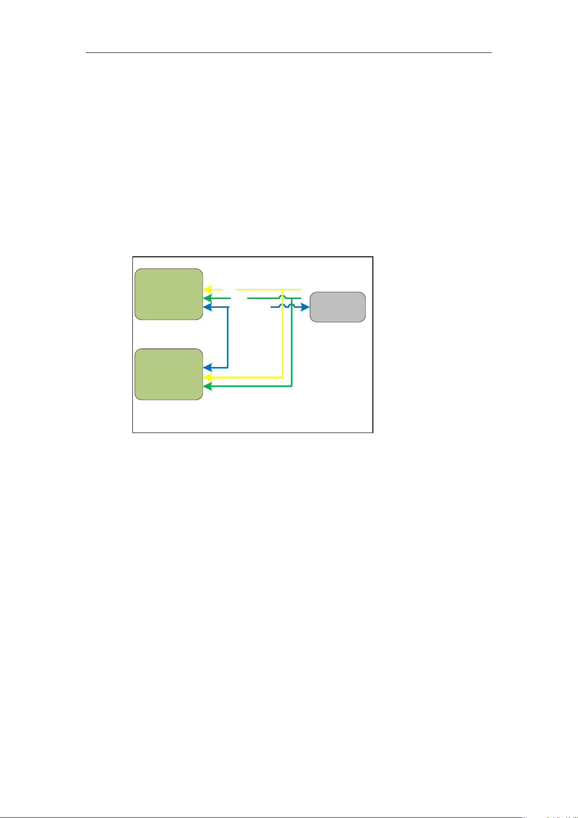
Master
Sensor
Slave
Sensor
Private CAN
IGN
GND
ECU
3 System description
3.1 System Introduce
Two 24 GHz narrow band sensors compose this system. Two major
functions are included which are BSD (Blind spot detection)and RCTA (Rear
cross traffic Alert).
3.2 System Diagram
ECU is built by customer. The communication interface between 2
sensors is CAN (Private CAN or sensor CAN). The information on this CAN is
vehicle data, sensor position setup data, warning parameter setup data and
normal warning data output.
3.3 Sub- system description
2 sub-systems are included which is BSD and RCTA
3.3.1 BSD function
Blind Spot Detection (BSD) Radar sensor is designed for short range
detection, the field of view is selected to cover the full blind spot warning
zone, which is defined in the related ISO norms (ISO- 17387) corresponding to
this application.
5
Page 6

3.3.2 RCTA (Rear Cross Traffic Alert)
The Rear Cross Traffic Alert (RCTA) system uses the same radar
infrastructure used for detecting vehicles in the blind spot (Blind Spot
Detection, BSD).
Some serious accidents are happen when driver are reversing out of
parking space (Refer to follow picture). The usual reason of these
accidents is because drivers either fail to see a vehicle or cyclist
approaching from the side or they see them too late. RCTA system
provides assistance to the driver to prevent this. It is activating when the
reverse gear is selected.
6
Page 7

4 Technical requirement
4.1 Basic parameter
Operation voltage range:9~16V
Typical operation voltage: 12V
Operation temperature:-30℃~+85℃
Maximum power consumption :7W
Operation frequency: 24GHZ (NB)
Water proof: IP67
4.2 Radar performance
Frequency : 24.075 – 24.225GHz (Left side)
24.065 – 24.215GHz (Right side)
FOV : 120 degree
range accuracy: 0.25m
range resolution:1m
velocity accuracy: 0.08 m/s
Velocity resolution: 0.31 m/s
Angular accuracy):+- 1degree
Maximum objects detection : 32
Cycle Time: 20.48ms
7
Page 8

Right side blind zone
7m2m0.4m
3.8~4.5m dynamic change
Center of the car
Left side blind zone
3.8~4.5m dynamic change
7m2m
0.4m
120°
120°
30m
30m
5 Function requirement
5.1 Detection
FOV is 120 degree.
5.2 Warning
5.2.1 Blind zone define of BSD system
The warning zone definition is as follow, and it can be adjusted if needed.
8
Page 9

Parameter
Description
Default value
Xf
Forward length of Alert region
2m
Xr
Backward length of Alert region
7m
Ys
Alert ignore area
0.4m
Thold_ToS
Warning hold time when target overtaking subject
0.5sec
Thold_SoT
Warning hold time when subject overtaking target
0.5sec
Vy_dynamic_alarm_min
The velocity minimum gate for dynamic y distance
18m/s
Vy_dynamic_alarm_max
The velocity maximum gate for dynamic y distance
38.75m/s
y_dynamic_alarm_min
Minimum gate of dynamic y distance
3.8m
y_dynamic_alarm_max
Maximum gate of dynamic y distance
4.5m
Y
Alert width
Variable
X
Alert length after rear bumper
Variable
Alert
Region
Car
Alert
Region
Ys
Y
Xf
Tracking
Object
A
Xr
V
Ys
Y
Tracking
Object
B
V
Unit: meter(m)
X
x
Extend
Alert
Region
Extend
Alert
Region
5.2.2 Parameter of BSD system
For Y:
If relative speed of object≦ Vy_dynamic_alarm_min then Y=
y_dynamic_alarm_min
If relative speed of object≧Vy_dynamic_alarm_max then Y=
y_dynamic_alarm_max
If Vy_dynamic_alarm_min <relative speed of object<
Vy_dynamic_alarm_max then Y is linear interpolation between
y_dynamic_alarm_min and y_dynamic_alarm_max.
9
Page 10

For X:
We have one linear formula as follow which is calculate from ISO 17387 Chapter 4
Table 3
T=0.1V +1.5 (where T is TTC and V is relative speed)
That means different relative speed, we have different TTC.
X=V*T
If VT≦Xr then X=Xr (fix)
If VT>Xr then X=VT (Dynamic)
10
Page 11

RCTA Zone
Center of the car
Typ. 30m base on TTC <2.0sec
7m
Typ. 30m base on TTC<2.0sec
5.2.3 RCTA zone of RCTA system
The RCTA zone definition is as follow, and it can be adjusted if needed.
The moving target which is with Speed between2.5m/sec~15m/sec and
enter left or right RCTA ZONE and have Potential collision TTC<2.0sec
The maximum subject car speed is not over 15km/hr.
11
Page 12

Parameter
Description
Default value
Xcf
Forward length of potential collision area
3m
Xcr
Backward length of potential collision area
5m
Yc
Width of each side (right or left)
0.8m
TTC_RCTA
Alert TTC setting
2sec
Car
Xcr
Tracking
Object
Xcf
Yc
Y
X
Xcf
Tracking
Object
Xcr
Yc
5.2.4 Parameter of RCTA system
Position of Tracking Object will fall into the potential collision Region (length is
Xcf+Xcr, Width is Yc for each side) with TTC within 2sec
5.3 Self diagnostic
System will do self diagnostic during the boot up and operation.
12
Page 13

6 Mechanical Requirement
6.1 Weight
Weight of Signal sensor is 285g
6.2 The size of sensor
144*98*23±0.3 mm (L*W*H)
Outline is as follow:
13
Page 14

6.3 Installation
There are 4 fix locations, please refer to follow:
The master sensor is installed inside the rear bumper of left, and the
connecter is down.
The slave sensor is installed inside the rear bumper of right, and the
connecter is down。 Please refer to follow
Azimuth angle is 57 degree
Elevation angle is 1~4 degree
The height of sensor is 30~80 cm
14
Page 15

NO
Signal Name
I/O/P
Description
Note
1
LED_L
P
HMI LED for left side
HMI
2
LED_R
P
HMI LED for right side
HMI
3
TURN_R
IO
Indicator signal for right side
Vehicle data
4
TURN_L
IO
Indicator signal for left side
Vehicle data
5
SPD
IO
Vehicle speed physical line
Vehicle data
6
VEHICLE_CAN_H
IO
Vehicle CAN bus
Vehicle data
7
GND
P
Power Ground
Ground
8
V_IN
P
Power Input
Power
9
---
IO
---
---
10
---
IO
---
---
11
BUZZER
P
HMI Buzzer
HMI
12
S_PRIVATE_CAN_L
IO
Sensor private CAN
To slave sensor
13
S_PRIVATE_CAN_H
IO
Sensor private CAN
To slave sensor
14
VEHICLE_CAN_L
IO
Vehicle CAN bus
Vehicle data
15
GND
P
Power Ground
Ground
16
V_IN
P
Power Input
Power
7 Connecter interface
7.1 Connecter
I/O connecter [16pin]: ACES: 50992-0161L-001
Wire connecter: Tyco 1438031-1
7.2 Pin define
8.2.1. Master sensor
15
Page 16

NO
Signal Name
I/O/P
Description
Note 1 ---
IO
---
---
2
---
IO
---
---
3
---
IO
---
---
4
---
IO
---
---
5
---
IO
---
---
6
---
IO
---
---
7
GND
P
Power Ground
Ground
8
V_IN
P
Power Input
Power
9
---
IO
---
---
10
---
IO
---
---
11
---
IO
---
---
12
S_PRIVATE_CAN_L
IO
Sensor private CAN
To Sensor
13
S_PRIVATE_CAN_H
IO
Sensor private CAN
To Sensor
14
---
IO
---
---
15
---
IO
---
---
16
---
IO
---
---
8.2.2. Slave sensor
16
 Loading...