

Page 1

Blind Spot Warning (BSW) and Rear Cross Traffic Alert (RCTA)
specification
Model Name: UMD-RI03, UMD-RI03 –L, UMD-RI03 -R
Version: V01
2018/2/21
Jimmy JW Chang
Page 2

Contents
1 Scope ...................................................................................................................................................... 3
2 Terms and definitions ............................................................................................................................ 3
3 Reference ............................................................................................................................................... 3
4 General description ................................................................................................................................ 4
4.1 System introduction ....................................................................................................................... 4
4.2 System diagram ............................................................................................................................. 4
4.3 Hardware Block Diagram .............................................................................................................. 4
4.3.1 Right and left side Sensor .............................................................................................................. 4
4.3.2 ECU control box ............................................................................................................................ 5
4.4 Software Implementat io n ............................................................................................................... 5
4.5 Software Block Diagram ............................................................................................................... 5
5 System Function Description ................................................................................................................. 6
5.1 Function definition ......................................................................................................................... 6
5.1.1 BSW function ................................................................................................................................ 6
5.1.2 RCTA function ............................................................................................................................... 7
5.2 Connecter pin define ...................................................................................................................... 8
6 Technical specification ........................................................................................................................ 10
6.1 Basic parameters: ......................................................................................................................... 10
6.2 Performance parameters: ............................................................................................................. 10
6.3 Field of View (FoV) ..................................................................................................................... 11
6.4 Detection target ............................................................................................................................ 11
6.5 The false alert rate and detection rate .......................................................................................... 11
7 Mechanical requirements ..................................................................................................................... 12
7.1 Weight .......................................................................................................................................... 12
7.2 Sensor size ................................................................................................................................... 12
7.3 Installation ................................................................................................................................... 13
8 System Function Design ...................................................................................................................... 15
8.1 BSW warning ............................................................................................................................... 15
8.2 RCTA warning ............................................................................................................................. 15
8.3 Self diagnostics ............................................................................................................................ 15
9 Design Verification .............................................................................................................................. 16
9.1 Environmental T e st ...................................................................................................................... 16
9.2 Performance test .......................................................................................................................... 16
10 Federal Communications Commission (FCC) Statement ............................................................ 17
Page 3

1 Scope
This document describ es the system dev el op men t of sm all for m factor (SFF) blind spot
warning (BSW). This is includes technical s pecification, system function design requirements,
mechanical design/ installation, software interface/communication and test verification.
2 Terms and definitions
BSW (Blind spot warning):This system assists drivers in driving safely by detecting and
warning them of the presence of other vehicles in the blind spot area
RCTA (Rear cross traffic alert): This function assists driver in rear gear by detecting and
warning them of other vehicle driving from side of rear.
24GHz ISM Band (Industrial scientific medical radio): It is radio bands (portions of the
radio spectrum) reserved internationally for the use of radio frequency (RF) energy for
industrial, scientific and medical purposes other than telecommunications. T he
frequency bandwidth 24~24.25 GHz can be used for worldwide radar application. We
also call this is Narrow Band Radar, which is different from ultra wide band radar.
FOV (Field of view): The maximum azimuth angle that radar system can detect the
target vehicle.
3 Reference
ISO 17387
ES-X82010
ISO16750
Page 4
Sensor(Left) Sensor (R)
IGN
GND
ECU with Buzzer
Private CAN
IGN
GND
Speed
IND_R/L
Rear light
ILL
LED_R
/L
4 General description
4.1 System introduction
This system is composed of two 24 GHz narrow-band sensors. Its intended function is for
blind spot warning (BSW) to assist driver for the driving safety.
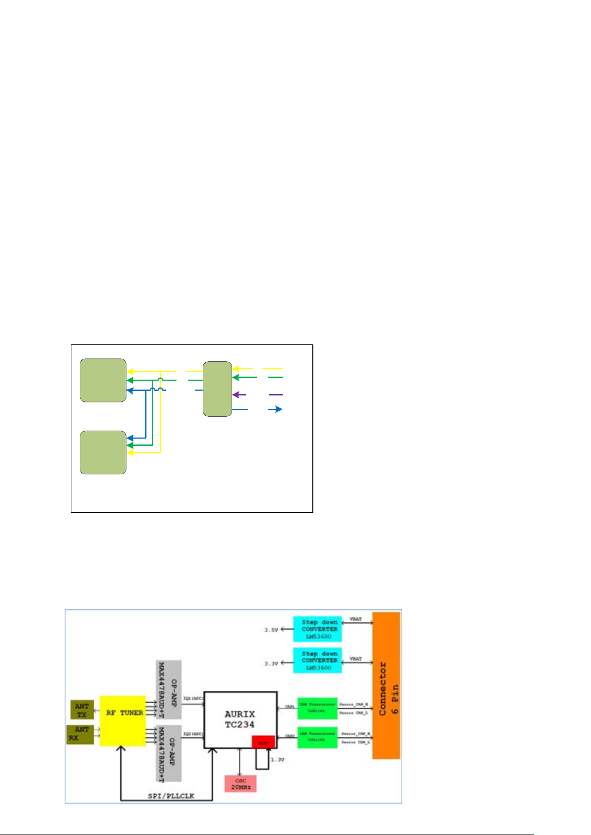
4.2 System diagram
The system includes a master sensor and a slave sensor. Two sensors are communicated
by “Private CAN”. The external interface is to connect with ignition power (IGN, 12V) and
CAN message of vehicle information.
The communication interface between two sensors is CAN (Private CAN). The information
transmitted through this CAN relates to vehicle data, sensor position setup data, warning
parameter setup data and normal warning data output.
ECU will transfer the vehicle data to sensors and control the HMI warning output.
4.3 Hardware Block Diagr a m
4.3.1 Right and left side Sensor
It is composed of RF tuner and DSP. It includes one Vehicle CAN (optional) and one Private
CAN.
Page 5
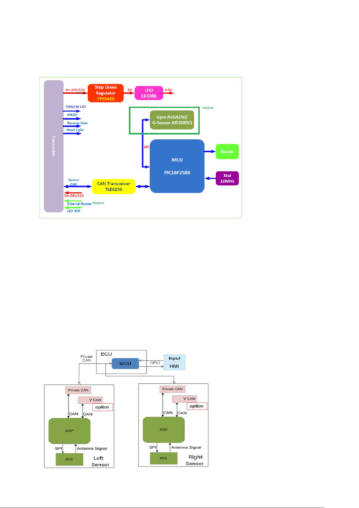
4.3.2 ECU control box
Ii is mainly composited by the MCU. It have radar conversion information 、HMI output an d
Gyro simulated the hardware of Yaw rate(Reserved) .
4.4 Software Implementation
MPLAB IDE V8.86
Matlab 2012b
The software design process is mainly for detection, tracking and warning. It also provides
self-diagnosis.
4.5 Software Block Diagram
The right and left sensor software structure shows below. The communication between right
and left sensor is through CAN, which is Private CAN.
Page 6
Right side Blind zone
7m
1m
0.5m
3m
Center of the car
Left side Blind zone
3m
7m
1m
0.5m
5 System Function Description
5.1 Function definition
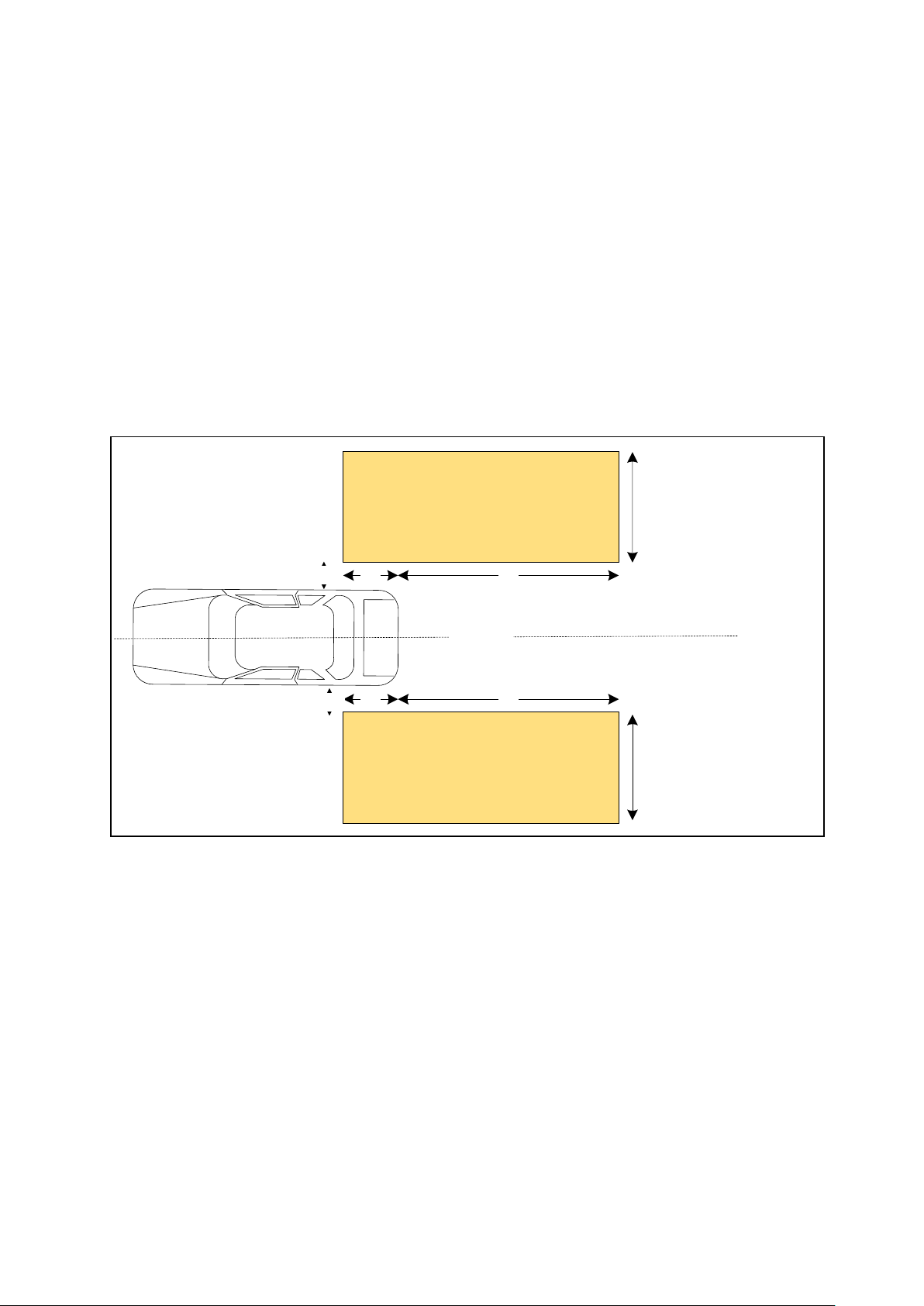
5.1.1 BSW function
BSW system is designed for monitoring adjacent lane and providing warning. The warning
zone definition is below.
The warning distance of passenger vehicle is 7m behind the rear of subject vehicle.
(Normal driving behavior for overtaking)
There is non-warning zone at side of vehicle 0.5m.
The warning width may be adjusted by subject vehicle speed.
The activation speed of system is 10km/h.
Page 7

Parameter
Description
Default
Unit
Xcf
The length of detection area from rear of subject vehicle in front.
1.5
m
Xcr
The length of detection area from rear of subject vehicle in in rear.
5
m
Yc
The length of center and edge of subject vehicle.
0.8
m
TTC_RCTA
Time to collision for RCTA
2.5
sec
Active_SPD_Min
The minimum active speed of RCTA
-10
kph
Active_SPD_Max
The maximum active speed of RCTA
0
kph
TV_Speed_min
The minimum speed of target vehicle
2
m/s
TV_Speed_Max
The maximum speed of target vehicle
8
m/s
5.1.2 RCTA function
RCTA warning area shows below. The collision time should be less than 2 seconds for the
collision area.
Page 8

6
V_IN
P
Power input
---
5
GND
P
Ground
---
4
S_PRIVATE_CAN_H
I/O
S_PRIVATE_CAN_L
2
VEHICLE_CAN_H
I/O
(Reserved)
1
VEHICLE_CAN_L
I/O
6
V_IN
P
Power input
---
5
GND
P
Ground
---
4
S_PRIVATE_CAN_H
I/O
S_PRIVATE_CAN_L
VEHICLE_CAN_H
Twist(Reserved)
VEHICLE_CAN_L
5.2 Connecter pin define
There are 2 sets 6 PIN connecter in the system, Follow is usage and pin define of connecter.
6 PIN connector (Left sensor):
Molex MLX0314036110
Usage:
Right sensor connection
Pin definition of connecter:
Pin No Signal Name I/O/P Usage
Private CAN Twist
3
I/O
Vehicle CAN
6 PIN connector (Right sensor):
Molex MLX0314036110
Usage:
Left sensor connection
Pin definition of connecter:
Pin No Signal Name I/O/P Usage
Note
Twist
Note
Private CAN Twist
3
2
1
I/O
O
O
Vehicle CAN
Page 9

ECU 24PIN connector:
HTH24FW
Usage:
Right and left sensor connection.
PIN definition as below:
Pin Definition Pin Definition
1 POWER_IN 13 POWER_IN
2 NA 14 GND
3 GND 15 GND
4 SPD 16 SW
5 VEHICLE_CAN_H (Reserve) 17 Reverse Signal
6 VEHICLE_CAN_L (Reserve) 18 Head Light
7 GND 19 Buzzer_EXT (reserve)
8 SENSOR_CAN_H 20 TURN_R
9 SENSOR_CAN_L 21 TURN_L
10 LED_GND 22 LED_GND
11 LED_GND 23 LED_R
12 SW_LED 24 LED_L
Page 10

6 Technical specification
6.1 Basic parameters:
Operating voltage range: 9 V–16 V
Typical operating voltage: 13.5 V
Ambient operating tem per ature: –40 °C to +85 °C
Maximum power consumption: 6 W
Operation frequency: 24 GHZ
Waterproofing: IP67
6.2 Performance parameters:
Frequency :
- 24.065 – 24.225Ghz (UMD-RI03)
- 24.075 – 24.225GHz (UMD-RI03 –L ) left side
- 24.065 – 24.215GHz (UMD-RI03 –R ) Right side
FOV: 120°
Channel number:1024
Output power:< 104.81 dBuV/m
Range accuracy: 0. 25 m
Range resolution: 1.0 m
Velocity accuracy: 0.08 m/s
V el oci ty resolution: 0.32m/s
Angle accuracy: +/-1 degree (between azimuth angle -40~+40 degrees)
Maximum number of tracking objects: 32
Cycle time: 40.96 ms
Page 11

6.3 Field of View (FoV)
The field of view angle is about 120 degrees.
6.4 Detection target
Truck, Passenger Car, Motorcycle.
6.5 The false alert rate and detection rate
Low false alert rate: Radar system has lower false alert rate even driving close to
complex envir onment. Th e false alert rate is l ower than 5 tim es w hen dri vi ng 100km.
Accurate detecti o n r ate (Low missing rate) : In normal driving cas e, t he acc ur at e r ate
is very high.
- 99% for Truck and Passenger Car
- 98% for Motorcycl e.
Page 12

7 Mechanical requirements
7.1 Weight
The sensor weight is 100±5g for each sensor.
7.2 Sensor size
90.4*83.1*18.93±3 mm (L*W*H)
The figure shows sensor outline below.
UMD-RI03, UMD-RI03 –R
UMD-RI03 -L
Page 13

7.3 Installation
There are three locations for affixing the device as illustrated in the following diagram.
The three locations for affixing are different between right and left sensor.
Left Right
2
Left sensor is installed i ns ide of bumper at le ft r ear s ide of subject car. The connector is
downward. Refer to figure below.
Right sensor is installed inside of bumper at right rear side of subject car. The
connector is downward. Refer to figure below.
Page 14

Azimuth angle = 45°。I t coul d foll ow the performance for adjusting .
Elevation angle = 0.5~3.5° , which is related to the instal l ati on hei g ht .
ECU box put on suitable place.
Page 15

8 System Function Design
8.1 BSW warning
When speed of subject vehicle reaches 10km/h, BSW system will monitor the vehicles at
adjacent lane. When there is vehicle at warning zone or closing to warning zone, the system
can monitor and provide the warning message by CAN bus and output warning by LED or
buzzer to prevent potential collision.
The system will provide two levels warning.
The first level warning will provide visual warning by LED.
The second level w arning w ill pr ovi de not onl y v i sual w arni ng, but als o acoustic warning,
like buzzer, to show the immediate risk. The buzzer design can be done by either in
ECU or in buzzer on vehicle.
8.2 RCTA warning
When driver selects rear gear, RCTA system will be enabled. When ther e i s tar g et c ar ent e r s
detection zone and it may cause potential collision (TTC 2.5 seconds), the system will
provide the LED and buzzer warning to remind driver. But if the speed of rear direction is
larger than 10km/h, the system will not guarantee coverage.
8.3 Self diagnostics
The system will perform self diagnostics d uring the boo t up. When radar system is operati ng,
it is still monitoring and inform driver once the system error message comes out, for exampl e
no CAN message from slave sensor.
Page 16

PERFORMANCE/ FUNCTION/ INSPECTION
EVALUATION
Total 45pcs
Low Temperature
shelf test
3 DAYS(4.10)
Low Temperature
Operation test
3 DAYS(4.11)
High Temperature
shelf test
4 DAYS(4.12)
High Temperature
Operation test
5 DAYS(4.13)
Temperature Cycle
test
10 DAYS(4.14)
Fluid Resistance
test - Coating Test
5 DAYS(4.28-1)
Dust test
1 DAY(4.19)
Dew formation
test
1 DAY(4.18)
Thermal and
humidity cycle test
10 DAYS(4.16)
Steady humidity
test
4 DAYS(4.17)
Fluid Resistance
test - Immersion
Test
1 DAY(4.28-2)
Thermal
characteristic test
1 DAY(4.24)
Ozone Resistance
Test
3 DAYS(4.27)
Water resistance
test - Rain
7 DAYS(4.25-1)
Water resistance
Test - Liquid
Dropping
1 DAY(4.25-2)
Salt Water Spray
Test
29 DAYS(4.26-1)
Salt Water Spray
Test
4 DAYS(4.26-2)
Vibration test
- Operating
3 DAYS(4.20-1)
Vibration test
- Not Operating
1 DAY(4.20-2)
Shock Test
1 DAY(4.21)
Drop Test
1 DAY(4.22)
Ehdurance test
42 DAYS(4.23)
Thermal Shock test
42 DAYS(4-15)
Supply Voltage
Fluctuation Test
(Electric Load)
0.5 DAY(4.2-1)
Supply Voltage
Fluctuation Test
(Engine Starting)
0.5 DAY(4.2-2)
Supply Voltage
Intermittent Test
(Battery Chattering)
0.5 DAY(4.3-1)
Supply Voltage
Intermittent Test
( IG Key Switch)
0.5 DAY(4.3-2)
Transient Voltage
Immunity Test
(Along Line)
0.5 DAY(4.7-1)
Transient Voltage
Immunity Test
(Except line)
0.5 DAY(4.7-2)
Radiated Transient
Voltage Test
0.5 DAY(4.7-3)
Transient Voltage
Impression Test
0.5 DAY(4.7-4)
Power Voltage
Reverse
Connection test
0.5 DAY(4.4)
Overvoltage test
(A method)
0.5 DAY(4.5-1)
Overvoltage test
(B method)
0.5 DAY(4.5-2)
Supply Voltage
Instantaneous
Interruption
0.5 DAY(4.6)
ESD test
(Handling)
1 DAY(4.8-1)
Group A – 3 pcs /
25days
Group B – 3 pcs /
16days
Group C – 3 pcs /
15days
Group D – 3 pcs /
6days
Group E – 3 pcs /
42days
Group F – 3 pcs /
42days
Group G – 3 pcs /
6days
Group H – 3 pcs /
12days
Group I – 6 pcs /
5days
Group J – 6 pcs /
1days
Group K – 3 pcs /
1 DAY
Group L – 3 pcs /
29days
ESD test
(Operation)
1 DAY(4.8-2)
Normal Power Supply
Voltage Test
0.5 DAY(4.1)
Conducted
Electrometric Test
3 DAYS(4.9.1)
Radiated
Electrometric Test
3 DAYS(4.9.2)
Broadband
Emission
Measurement
1 DAYS(4.9.3)
Narrowband
Emission
Measurement
2 DAYS(4.9.4)
Group M – 3 pcs /
3 DAY
CISPR 25 Test
NCC/FCC
Certifcation
9 Design Verification
9.1 Environmental Test
Refer to the test flow and test item below.
9.2 Performance test
Refer to ISO17387 for stationary, dynamic test and road test.
Page 17

10 Federal Communicati ons Com mi s s ion ( FCC) S t a t e m ent
You are cautioned that changes or modifications not expressly approved by the part responsible for
compliance could void the user’s authority to operate the equipment.
This equipment has been tested and found to comply with the limits for a Class B digital device, pursuant
to part 15 of the FCC rules. These limits are designed to provide reasonable protection against harmful
interference in a residential installation. This equipment generates, uses and can radiate radio frequency
energy and, if not installed and used in accordance with the instructions, may cause harmful interference
to radio communications. However, there is no guarantee that interference will not occur in a particular
installation. If this equipment does cause harmful interference to radio or television reception, which can
be determined by turning the equipment off and on, the user is encouraged to try to correct the
interference by one or more of the following measures:
-Reorient or relocate the receiving antenna.
-Increase the separation between the equipment and receiver.
-Connect the equipment into an outlet on a circuit different from that to which the receiver is connected.
-Consult the dealer or an experienced radio/TV technician for help.
This device complies with Part 15 of the FCC Rules. Operation is subject to the following two conditions:
1) this device may not cause harmful interference, and
2) this device must accept any interference received, including interference that may cause undesired
operation of the device.
FCC RF Radiation Exposure Statement:
1. Th is Transmitter must not be co-located or operating in conjunction with any other antenna or
transmitter.
2. This equipment complies with FCC RF radiation exposure limits set forth for an uncontrolled
environment. This equipment should be installed and operated with a minimum distance of 20
centimeters between the radiator and your body.
 Loading...