

Page 1
M2M6270T User Guide
The document of content is consist of 3 part:
Section A: Main Board user guide
A-1. Function description of all key components
A-2. Jumper setting
Section B: Adapter Board user guide
B-1. Function description of all key components
B-2. Jumper setting
Section C: Jumper default setting
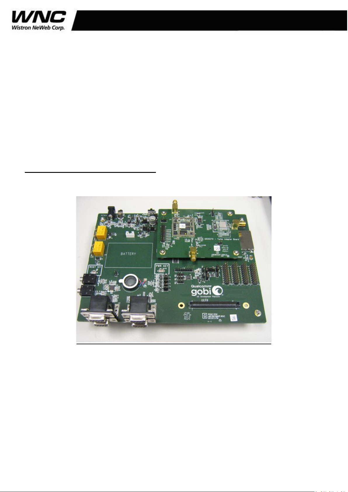
Section A: Main Board user guide
A-1.Function description of all key components
1/20
Page 2

M2M6270T User Guide
Interface board connection directions:
a. DC jack
The adapter must be in the range 5V~6.5V and can supply over 1.5A.
b. DC power switch
Switch to right direction for supplying VBAT to the module.
Otherwise, switch to left direction to turn off VBAT.
2/20
Page 3

M2M6270T User Guide
c. USIM socket
The purpose of the socket is to insert SIM card.
d. Micro USB
This USB has some main functions:
(a) Download firmware.
(b)Send AT command.
(c)Trace GPS log
e. Adaptor board Conn.
This is for the purpose of connecting main board and adaptor board.
f. SD card socket
The purpose of the socket is to insert SD card or some SDIO interface
module.
g. Audio in (mic)
This is a differential input microphone.The audio generator can generate
a tone to 6270T module through this jack for testing.
h. Accessory board Conn. (HPGP)
This is for the purpose of connecting main board and accessory
board(HPGP).
i. Power key
Press this key to power on/off 6270T module.
j. RS232 Conn for UART&GPIO24~GPIO27
This is a stacked DSUB-9 connector. The upper one is for QSC6270T
UART and the other is reserved for GSBI UARTs in the future (like 9x15).
k. RS232 Conn for GPIO21,GPIO22,GPIO34&GPIO35
These DSUB-9 connectors are reserved for GSBI UARTs in the future (like
9x15).
3/20
Page 4

M2M6270T User Guide
l. PCM CODEC input
The analog audio pass through this jack and encoded by PCM
CODEC(TLV320AIC1110).
m. PCM CODEC output
6270T PCM signals are decoded by PCM CODEC(TLV320AIC1110) and
Output from this audio jack.
n. Audio output(Speaker)
This is analog audio output path of 6270T module
o. Battery Conn
This is battery connector which supplies VBAT to 6270T module.
A-2. JUMP setting
A-2.1 VREG_IN:
JP2.1 short to JP2.2 Translated to 5V/3.3V/1.8V/1.2V from adapter.
JP2.2 short to JP2.3 Translated to 5V/3.3V/1.8V/1.2V from battery.
4/20
Page 5

M2M6270T User Guide
A-2.2 Battery charger switch
JP19.1 short to JP19.2 Use internal (QSC6270T) charger function.
JP19.2 short to JP19.3 Use external (charger IC on main board) charger
function.
A-2.3 BATT_THERM to Charge IC
Short this JP4 to connect BATT_THERM to external charge IC on main
board.
5/20
Page 6

M2M6270T User Guide
A-2.4 BATT_THERM to Fuel Gauge IC
Short this jump(JP5) to connect BATT_THERM to Fuel Gauge IC
thermostat.
To avoid BATT_THERM read interference, if short JP5, suggest to remove
JP6 jump (Disconnect BATT_THERM with QSC6270T).
A-2.5 Battery thermostat switch
JP21.1 short to JP21.2 Use 22kΩ resistor as battery thermostat for testing.
JP21.2 short to JP21.3 Use the real external battery thermostat.
6/20
Page 7

M2M6270T User Guide
A-2.6 BATT_THERM path to 120 pin connector
Short this jump(JP6) to connect BATT_THERM to QSC6270T.
7/20
Page 8

M2M6270T User Guide
JP15.1 short to JP15.2
JP16.1 short to JP16.2
JP17.1 short to JP17.2
JP18.1 short to JP18.2
JP15.2 short to JP15.3
JP16.2 short to JP16.3
JP17.2 short to JP17.3
JP18.2 short to JP18.3
G-sensor controlled by I2C interface
G-sensor controlled by SPI interface
A-2.7 VBAT switch
JP1.1 short to JP1.2 Use 5V~6.5V DC jack power to supply VBAT to
JP1.2 short to JP1.3 Use external battery power to supply VBAT to
module.
A-2.8 G-sensor interface switch
8/20
Page 9

M2M6270T User Guide
A-2.9 G-sensor switch
Short this JP11 to connect GPIO6 with G-sensor interrupt pin,
If GPIO6 has been reserved for other use, disconnect JP11 for avoiding
interference.
A-2.10 GPIO7 switch
Short this JP12 to connect GPIO7 with Light-sensor interrupt pin,
If GPIO7 has been reserved for other use, disconnect JP12 for avoiding
interference
9/20
Page 10

M2M6270T User Guide
A-2.11 GPIO9 switch
Short this JP13 to connect GPIO9 with Temperature-sensor interrupt pin,
If GPIO9 has been reserved for other use, disconnect JP13 for avoiding
interference.
A-2.12 SPI level shifter
JP14.1 short to JP14.2 Put the jumps on JP14 pin1/2 to select level
shifter 3.3V voltage for SPI
JP14.2 short to JP14.3 Put the jumps on JP14 pin2/3 to select level
shifter 1.8V voltage for SPI
10/20
Page 11

M2M6270T User Guide
A-2.13 ADC Multiplexer input
Header JP10 is external ADC Multiplexer input.
A-2.14 ADC Multiplexer channel switch
The ADC Multiplexer supports up to 8 channels. And these jumpers
configure the Multiplexer channel connection to 6270T ADC.
JP7.1 short to JP7.2 configure GPIO1 to high
JP7.2 short to JP7.3 configure GPIO1 to low
JP8.1 short to JP8.2 configure GPIO2 to high
JP8.2 short to JP8.3 configure GPIO2 to low
JP9.1 short to JP9.2 configure GPIO3 to high
JP9.2 short to JP9.3 configure GPIO3 to low
11/20
Page 12

M2M6270T User Guide
GPIO3
GPIO2
GPIO1
Multiplexer
channel
L
L
L
1
L
L
H
2
L
H
L
3
L
H
H
4
H
L
L
5
H
L
H
6
H
H
L
7
H
H
H
8
12/20
Page 13

M2M6270T User Guide
A-2.15 GPIO14/GPIO15/GPIO16/GPIO17/GPIO18 indicator
P2 GPIO14. Short P2 to connect GPIO14 to LED indicator.
P3 GPIO15. Short P3 to connect GPIO15 to LED indicator.
P4 GPIO16. Short P4 to connect GPIO16 to LED indicator.
P5 GPIO17. Short P5 to connect GPIO17 to LED indicator.
P6 GPIO18. Short P6 to connect GPIO18 to LED indicator.
13/20
Page 14

M2M6270T User Guide
Section B: Adapter Board user guide
B-1. Function description of all key components
14/20
Page 15

M2M6270T User Guide
a. RF Antenna in
This is for the connection with GSM/UMTS antenna.
b. Wifi Antenna in
This is for the connection with WiFi antenna.
c. GPS Antenna in
This is for the connection with GPS antenna.
15/20
Page 16

M2M6270T User Guide
d. JTAG connector
JTAG ICE connector.
e. Adaptor board connector
This is for the purpose of connecting main board and adaptor board.
B-2 JUMP setting
B-2.1 Header JP6 is a test header of MPP1~MPP3.
Section 3: Jumper default setting
16/20
Page 17

M2M6270T User Guide
6270T whole system board
: 1.Use battery as module VBAT supply.
(Please insert battery connector to PWR2 before power on module)
:2.Use QSC6270T internal charger function.
:3.Connect Battery internal thermistor (10K ohm) to QSC6270T.
:4.Translated to 5V/3.3V/1.8V/1.2V from adapter.
17/20
Page 18

M2M6270T User Guide
5. G-sensor controlled by SPI interface
6. Connect 5 GPIOs to LED indicator.
18/20
Page 19

M2M6270T User Guide
7. Select SPI level shifter to 3.3V level.
Federal Communication Commission Interference Statement
This device complies with Part 15 of the FCC Rules. Operation is subject to the following two conditions:
(1) This device may not cause harmful interference, and (2) this device must accept any interference
received, including interference that may cause undesired operation.
This equipment has been tested and found to comply with the limits for a Class B digital device, pursuant
to Part 15 of the FCC Rules. These limits are designed to provide reasonable protection against harmful
interference in a residential installation. This equipment generates, uses and can radiate radio frequency
energy and, if not installed and used in accordance with the instructions, may cause harmful interference
to radio communications. However, there is no guarantee that interference will not occur in a particular
installation. If this equipment does cause harmful interference to radio or television reception, which
can be determined by turning the equipment off and on, the user is encouraged to try to correct the
interference by one of the following measures:
- Reorient or relocate the receiving antenna.
- Increase the separation between the equipment and receiver.
- Connect the equipment into an outlet on a circuit different from that
to which the receiver is connected.
- Consult the dealer or an experienced radio/TV technician for help.
19/20
Page 20

M2M6270T User Guide
FCC Caution: Any changes or modifications not expressly approved by the party responsible for
compliance could void the user's authority to operate this equipment.
This transmitter must not be co-located or operating in conjunction with any other antenna or transmitter.
Radiation Exposure Statement:
This equipment complies with FCC radiation exposure limits set forth for an uncontrolled environment.
This equipment should be installed and operated with minimum distance 20cm between the radiator &
your body.
20/20
 Loading...