

Page 1
□ Normal □ Internal Use Confidential □ Restricted Confidential 1 / 42
Product Technical Specifications
Project Name: IMA2A series
Author: Wistron NeWeb Corporation
Revision: 1.0
Revision Date: 2018/7/27
Page 2
□ Normal □ Internal Use
Confidential □ Restricted Confidential
2/42
Contact Information
Technical Support Website
https://supportiot.wnc.com.tw/
Company Website
www.wnc.com.tw
Rev. #
Author
Summary of Changes
Date
1.0
WNC
First official release
2018/7/27
Revision History
Product Technical Specifications
Page 3

Product Technical Specifications
□ Normal □ Internal Use
Confidential □ Restricted Confidential
3/42
© Wistron NeWeb Corporation
THIS DOCUMENT AND THE INFORMATION CONTAINED HEREIN IS PROPRIETARY AND
IS THE EXCLUSIVE PROPERTY OF WNC AND SHALL NOT BE DISTRIBUTED,
REPRODUCED, OR DISCLOSED IN WHOLE OR IN PART WITHOUT PRIOR WRITTEN
PERMISSION FROM WNC.
LIMITATION OF LIABILITY
THIS DOCUMENT AND THE INFORMATION CONTAINED HEREIN IS PURELY FOR
DESIGN REFERENCE AND SUBJECT TO REVISION BY WNC AT ANY TIME. NOTHING IN
THIS DOCUMENT SHALL BE CONSTRUED AS GRANTING ANY WARRANTY OR RIGHT
TO USE THE MATERIAL CONTAINED HEREIN WITHOUT WNC’S PRIOR EXPRESS
WRITTEN CONSENT. WNC SHALL NOT BE LIABLE FOR ANY USE, APPLICATION OR
DEVELOPMENT DERIVED FROM THE MATERIAL WITHOUT SUCH PRIOR EXPRESS
WRITTEN CONSENT.
Responsible company : W-NeWeb Corporation
Responsible address: 1525 McCarthy Blvd, Suite 206, Milpitas, CA 95035, U.S.A.
Responsible name: Chun Tsung Lee
Contact Number: +1 4084576800 #6802
Page 4

Product Technical Specifications
□ Normal □ Internal Use
Confidential □ Restricted Confidential
4/42
FCC Regulations:
This device complies with part 15 of the FCC Rules. Operation is subject to the
following two conditions: (1) This device may not cause harmful interference, and (2)
This device must accept any interference received, including interference that may
cause undesired operation.
This device has been tested and found to comply with the limits for a Class B digital
device , pursuant to Part 15 of the FCC Rules. These limits are designed to provide
reasonable protection against harmful interference in a residential installation. This
equipment generates, uses and can radiated radio frequency energy and, if not
installed and used in accordance with the instructions, may cause harmful
interference to radio communications. However, there is no guarantee that
interference will not occur in a particular installation If this equipment does cause
harmful interference to radio or television reception, which can be determined by
turning the equipment off and on, the user is encouraged to try to correct the
interference by one or more of the following measures:
-Reorient or relocate the receiving antenna.
-Increase the separation between the equipment and receiver.
-Connect the equipment into an outlet on a circuit different from that to which the
receiver is connected.
-Consult the dealer or an experienced radio/TV technician for help.
Caution: Changes or modifications not expressly approved by the party responsible
for compliance could void the user‘s authority to operate the equipment.
RF Exposure Information
This device complies with FCC radiation exposure limits set forth for an uncontrolled
environment. In order to avoid the possibility of exceeding the FCC radio frequency
exposure limits, human proximity to the antenna shall not be less than 20cm (8
inches) during normal operation.
Standalone Condition:
。8 dBi in 700 MHz Band
。5 dBi in 1700 MHz Band
。5 dBi in 1900 MHz Band
Assuming collocated with a WLAN transmitter with maximum 20 dBm average EIRP power
Page 5

Product Technical Specifications
□ Normal □ Internal Use
Confidential □ Restricted Confidential
5/42
Remark: This assumption is not valid if the output power of the collocated WLAN transmitter is higher
than 20 dBm.
。7 dBi in 700 MHz Band
。4 dBi in 1700 MHz Band
。4 dBi in 1900 MHz Band
ISED Notice
This device complies with Innovation, Science and Economic Development
Canada license-exempt RSS standard(s). Operation is subject to the following two
conditions:
(1) this device may not cause interference, and
(2) this device must accept any interference, including interference that may cause
undesired operation of the device.
Le présent appareil est conforme aux CNR Innovation, Sciences et Développement
économique Canada applicables aux appareils radio exempts de licence.
L'exploitation est autorisée aux deux conditions suivantes:
(1) l'appareil ne doit pas produire de brouillage, et
(2) l'utilisateur de l'appareil doit accepter tout brouillage radioélectrique subi, même si
le brouillage est susceptible d'en
Innovation, Science and Economic Development Canada ICES-003 Compliance
Label:
CAN ICES-3 (B)/NMB-3(B)
This Class B digital apparatus complies with Canadian ICES-003.
Cet appareil numérique de la classe B est conforme à la norme NMB-003 du Canada.
ISED Radiation Exposure Statement
This device complies with RSS-102 radiation exposure limits set forth for an
uncontrolled environment. In order to avoid the possibility of exceeding the ISED
radio frequency exposure limits, human proximity to the antenna shall not be less
than 20cm (8 inches) during normal operation.
Cet appareil est conforme aux limites d'exposition aux rayonnements de la CNR-102
définies pour un environnement non contrôlé. Afin d'éviter la possibilité de dépasser
les limites d'exposition aux fréquences radio de la CNR-102, la proximité humaine à
l'antenne ne doit pas être inférieure à 20 cm (8 pouces) pendant le fonctionnement
normal.
Page 6

Product Technical Specifications
□ Normal □ Internal Use
Confidential □ Restricted Confidential
6/42
IMPORTANT NOTE:
This module is intended for OEM integrator. The OEM integrator is still responsible
for the FCC compliance requirement of the end product, which integrates this module.
20cm minimum distance has to be able to be maintained between the antenna and
the users for the host this module is integrated into. Under such configuration, the
FCC radiation exposure limits set forth for an population/uncontrolled environment
can be satisfied.
Any changes or modifications not expressly approved by the manufacturer could void
the user's authority to operate this equipment.
USERS MANUAL OF THE END PRODUCT:
In the users manual of the end product, the end user has to be informed to keep at
least 20cm separation with the antenna while this end product is installed and
operated. The end user has to be informed that the FCC radio-frequency exposure
guidelines for an uncontrolled environment can be satisfied. The end user has to also
be informed that any changes or modifications not expressly approved by the
manufacturer could void the user's authority to operate this equipment. If the size of
the end product is smaller than 8x10cm, then additional FCC part 15.19 statement is
required to be available in the users manual: This device complies with Part 15 of
FCC rules. Operation is subject to the following two conditions: (1) this device may
not cause harmful interference and (2) this device must accept any interference
received, including interference that may cause undesired operation.
LABEL OF THE END PRODUCT:
The final end product must be labeled in a visible area with the following " Contains
Transmitter Module FCC ID: NKRIMA2A". If the size of the end product is larger than
8x10cm, then the following FCC part 15.19 statement has to also be available on the
label: This device complies with Part 15 of FCC rules.
Operation is subject to the following two conditions: (1) this device may not cause
harmful interference and (2) this device must accept any interference received,
including interference that may cause undesired operation.
The Innovation, Science and Economic Development Canada certification label of a
module shall be clearly visible at all times when installed in the host device;
otherwise, the host device must be labeled to display the Innovation, Science and
Economic Development Canada certification number for the module, preceded by the
words “Contains transmitter module IC:4441A-IMA2A”.
Page 7

Product Technical Specifications
□ Normal □ Internal Use
Confidential □ Restricted Confidential
7/42
Contents
Contact Information............................................................................................................................ 2
Revision History..................................................................................................................................2
Contents...............................................................................................................................................7
1.Introduction..................................................................................................................................... 9
1.1 General Features
1.2 Architecture.........................................................................................................................10
1.3 Connection Interface...........................................................................................................10
1.4 Environmental Specifications and Certifications
1.4.1 Environmental Specifications
1.4.2 Certifications
1.4.3 Green Product Compliance
2
. Pin Definitions
2.1 LGA Module Pin Diagram..................................................................................................12
2.2 LGA Module Pin Definitions..............................................................................................12
3
. Electrical Specifications
3.1 Power Supply...................................................................................................................... 16
Power Consumption............................................................................................................16
3.2
3.3Control Interfaces................................................................................................................17
3.3.1 Power-On Signal
3.3.2 Wake-Up Interface
3.3.3 Reset Signal
3.3.4 WWAN state
3.4UART Interface...................................................................................................................18
3.5UIM Interface......................................................................................................................19
3.6I/O Characteristics...............................................................................................................20
3.7EJTAG Interface................................................................................................................. 21
3.
8 ADC
3.9 RF Interface.........................................................................................................................22
3. 9.1 Bandwidth Support
3. 9.2 RF Transmission Specifications
3. 9.3 RF Receiver Specifications
3.9.4 RF GNSS Receiver Specifications
4.Mechanical Information................................................................................................................ 25
4.1 Physical Dimensions........................................................................................................... 25
4.2 Pin Dimensions................................................................................................................... 26
4.3 Marking Information...........................................................................................................28
5.Packing Information......................................................................................................................29
5.1 Tape-and-Reel Package.......................................................................................................29
5.2 Single Packaging for Samples.............................................................................................30
6.Design Guide.................................................................................................................................31
6.1 Power Trace Design............................................................................................................31
............................................................................................................................... 12
Interface.......................................................................................................................21
...................................................................................................................9
....................................................................10
.................................................................................. 10
............................................................................................................ 11
......................................................................................11
.................................................................................................................16
.......................................................................................................17
...................................................................................................17
.............................................................................................................. 18
.............................................................................................................18
................................................................................................. 22
............................................................................... 23
.......................................................................................23
..............................................................................23
Page 8

Product Technical Specifications
□ Normal □ Internal Use
Confidential □ Restricted Confidential
8/42
6.2 RF Layout guidance.........................................................................................................32
6.3 RF Matching Guide.............................................................................................................34
6.4 GNSS External Circuit Design........................................................................................... 34
6.5 Interference and Sensitivity................................................................................................ 35
6.6 Antenna design requirement
6.7 Mounting Considerations....................................................................................................37
6.8 PCB Pad Design..................................................................................................................39
6.9 Stencils................................................................................................................................ 40
6.10 LTE Power Saving Mode..................................................................................................40
7.Safety Recommendations..............................................................................................................41
8.Initialisms......................................................................................................................................42
..............................................................................................36
Page 9
□ Normal □ Internal Use Confidential □ Restricted Confidential 9 / 42
1.Introduction
The WNC IMA2A series modules include the Altair ALT1250 Cat. M1 baseband, a
Band
Uplink (MHz)
Downlink (MHz)
LTE Band 2
1,850–1,910
1,930–1,990
LTE Band 4
1,710–1,755
2,110–2,155
LTE Band 12
699–716
729–746
Module
Power class
GNSS
IMA2A
3
General interfaces
• JTAG
• USIM
• GPIO
• UART
Supported
frequency bands
• LTE Band 2
• LTE Band 4
• LTE Band 12
Operating voltage
• VCC(range: 3.3 V–4.2 V)
Packaging
• LGA module
• 104 pads (19.2 mm × 14.7 mm × 2.152 mm)
• RoHS compliant
Standards
compliance
• 3GPP Release 13–compliant; software upgradable to
Release 14
PHY
• Category M1: Up to 300 Kbps DL/375 Kbps UL
• HD-FDD duplexing support
complete LTE RF front-end, memory, and required circuitry to fulfill 3GPP E-UTRA
and AT&T Wireless LTE Cat. M1 UE specifications. The following table enumerates
the frequencies supported by the IMA2A series modules.
Table 1-1. Band support
Table 1-2 SKU description
1.1 General Features
The table below summarizes the IMA2A module features.
Table 1-3. General features of the IMA2A
Page 10
Product Technical Specifications
□ Normal □ Internal Use
Confidential □ Restricted Confidential
10/42
• Power-saving mode
MAC
• Random access procedure in normal subframes
• Scheduling request, buffer status reporting, and power
headroom reporting
• Discontinuous reception (eDRX) with long and short cycles
• IPv4, IPv6
NAS and above
• NAS
• SMS over SG
Table 1-4. LTE-related features of the IMA2A
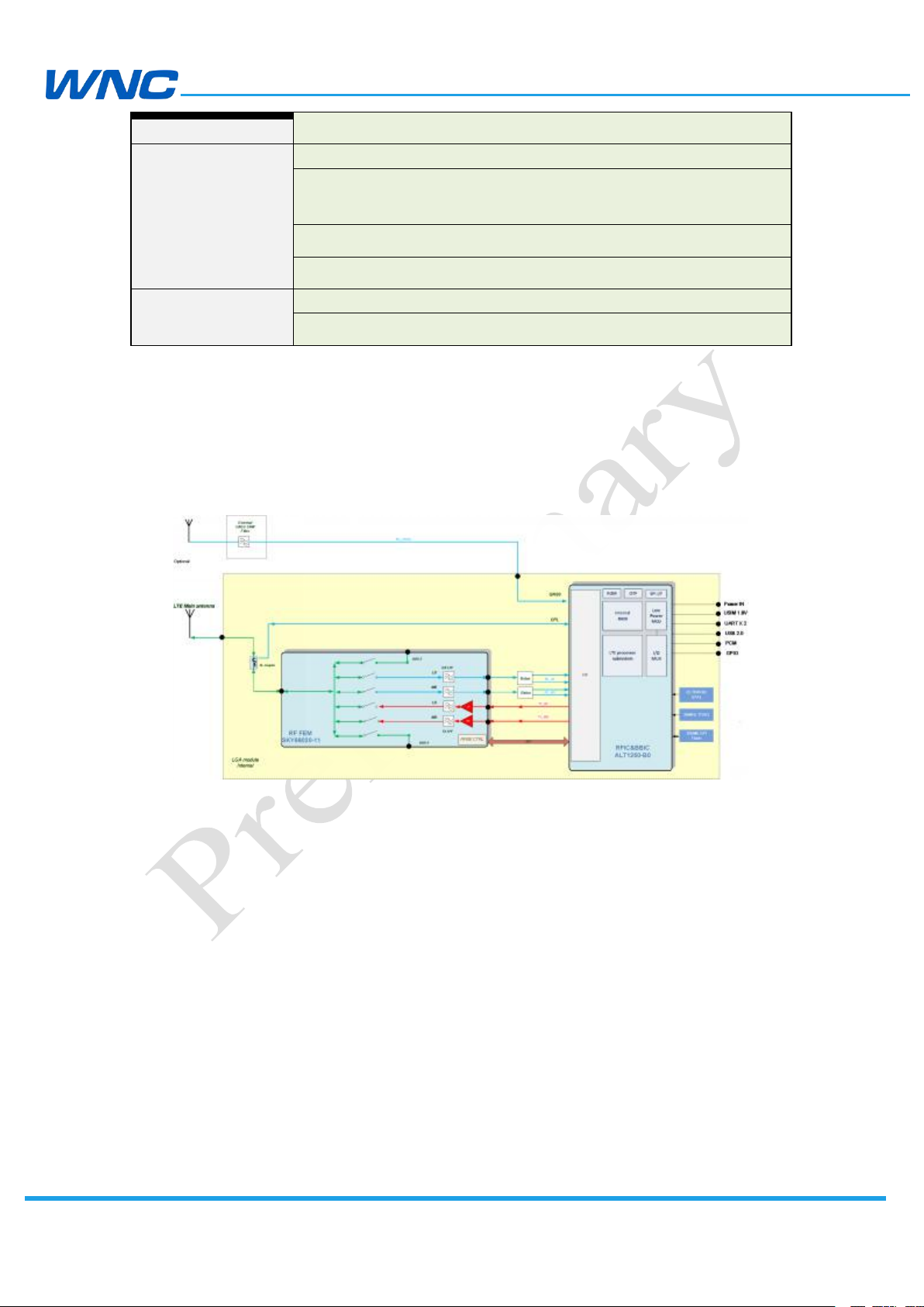
1.2 Architecture
The architecture block diagram of the IMA2A is presented in Figure 1-1 below.
Figure 1-1. IMA2A block diagram
1.3 Connection Interface
The IMA2A module is a LGA device. All electrical and mechanical connections are
made through the 104 pads on the bottom side of the PCB.
1.4 Environmental Specifications and Certifications
1.4.1 Environmental Specifications
The environmental specifications for both operating and storage conditions are
Page 11
Product Technical Specifications
□ Normal □ Internal Use
Confidential □ Restricted Confidential
11/42
Condition
Temperature Range
Remark
Normal ambient
operating temp. range
–20 °C to 60 °C
Fully functional and complies with 3GPP
specifications
Extended ambient
operating temp. range
–40 °C to 85°C
RF performance may be affected outside normal
ambient operating range temp., although the
module will still function.
Storage
–40 °C to 85 °C
defined in the table below.
Table 1-5. Temperature range
1.4.2 Certifications
The IMA2A module is compliant with the following regulations: PTCRB, FCC, IC, and
AT&T TA.
1.4.3 Green Product Compliance
RoHS (2011/65/EU)
Page 12

□ Normal □ Internal Use
Confidential □ Restricted Confidential
12/42
2.Pin Definitions
2.1 LGA Module Pin Diagram
Pin No.
Name
Description
7
GND
GND
8
GND
GND
9
RF_GNSS
RF_GNSS_ANT
10
GND
GND
11
GND
GND
12
GND
Ground
13
GND
Ground
The IMA2A LGA module pin layout is illustrated below.
Product Technical Specifications
Figure 2-1. IMA2A LGA module pin layout (top view)
2.2 LGA Module Pin Definitions
The signals and all the related details are listed in the below table.
Page 13
Product Technical Specifications
□ Normal □ Internal Use
Confidential □ Restricted Confidential
13/42
14
GND
Ground
15
Main antenna
Main antenna port
16
GND
Ground
17
GND
Ground
18
GND
Ground
19
GND
Ground
20
GND
Ground
21
NC
Not connected
22
GND
Ground
23
GND
Ground
24
GND
Ground
25
GND
Ground
26
GND
Ground
27
NC
Not connected
28
GND
Ground
29
GND
Ground
30
GND
Ground
37
Power
Power
38
Power
Power
39
Power
Power
40
Power
Power
41
Power
Power
42
Power
Power
43
PMU_VBACKUP
Power input for real time clock
44
GND
Ground
45
GND
Ground
46
PCM_FS/GPIO46
PCM/General purpose input/output
47
PCM_IN/GPIO47
PCM/General purpose input/output
48
PCM_OUT/GPIO48
PCM/General purpose input/output
49
PCM_CLK/GPIO49
PCM/General purpose input/output
50
GND
Ground
51
GND
Ground
52
I2C1_SCL/GPIO01
I2C/General purpose input/output
53
I2C1_SDA/GPIO02
I2C/General purpose input/output
80
PMU_AT_IN
Anti-tamper input
81
PMU_AT_OUT
Anti-tamper output
82
PMU_EXT_ALARM
Alarm output
83
DEBUG_SEL
Hardware pin for EJTAG chain selection
Page 14

Product Technical Specifications
□ Normal □ Internal Use
Confidential □ Restricted Confidential
14/42
84
GND
Ground
85
GND
Ground
86
USB_Dp
USB data positive
87
VBUS
USB 3.3V input voltage supply
88
USB_Dn
USB data negative
89
GND
Ground
90
GND
Ground
91
GND
Ground
92
UART0_CTS
Clear to send for UART 0
93
UART0_TX
Transmit for UART 0
94
UART2_TX
Transmit for UART 2
95
UART0_RX
Receive for UART 0
96
UART2_RX
Receive for UART 2
97
UART0_RTS
Request to send for UART 0
98
UART2_RTS
Request to send for UART 2
99
UART2_CTS
Clear to send for UART 2
100
GPIO100
General purpose input/output
101
GNSS_EN
For external LNA enable
102
GPIO102
General purpose input/output
103
GPIO103
General purpose input/output
130
ADC1
Analog-to-digital converter
131
ADC2
Analog-to-digital converter
132
GPIO08
General purpose input/output
133
UIM_VCC
SIM card power
134
UIM DATA
SIM card data line
135
UIM CLK
SIM card clock line
136
UIM RESET
SIM card reset line
137
UIM DETECT
SIM card detect line
138
NC
Not connected
139
GND
Ground
140
GND
Ground
141
WWAN_STATE
Wireless WAN radio state
142
Power on
1
Power-on of the module (RFU)
143
WAKEUP_OUT
Module wake-up of the host
144
WAKEUP_IN
2
Host wake-up of the module
145
RESET
Hardware reset signal
146
VREF
3
Reference logic voltage (1.8 V voltage)
201
EJ_TCK
EJ_TCK
202
EJ_TDI
EJ_TDI
Page 15

Product Technical Specifications
□ Normal □ Internal Use
Confidential □ Restricted Confidential
15/42
203
EJ_TDO
EJ_TDO
204
EJ_TMS
EJ_TMS
205
EJ_TRST
EJ_TRST
206
DEBUG_RSTN
Reset pin for the JTAG probe
208
GND
Ground
209
GND
Ground
210
GND
Ground
211
GND
Ground
212
GND
Ground
213
GND
Ground
214
GND
Ground
215
GND
Ground
216
GND
Ground
217
GND
Ground
218
GND
Ground
219
GND
Ground
220
GND
Ground
221
GND
Ground
222
GND
Ground
223
GND
Ground
Table 2-1. IMA2A module pin definitions
Notes:
1: Leave pin 142 floating; the module can be turned on automatically when a power
supply exists.
2: Pin 144 can be used as a wake-up as the module enters deep-sleep status. The
default configuration is active high to wake up the LGA module.
3: The VREF voltage will turn off when entering the deep sleep state.
4:UART signal is better to retain in low state before the ALT1250 voltage is ready.
5:145 pin EXT_RST_N should use external 1.8V for pull up voltage
Page 16

Product Technical Specifications
□ Normal □ Internal Use
Confidential □ Restricted Confidential
16/42
3.Electrical Specifications
Direction
Minimum
Typical
Maximum
Power (37–42)
In
3.3 V
3.8 V
4.2 V
VREF
Out
1.71 V
1.8 V
1.89 V
SIM_VCC (1.8 V)
Out
1.71 V
1.8 V
1.89 V
Powering on
Conditions
Result
Peak power consumption
TBD
TBD
Power off
Conditions
Result
Power off consumption
Only the module; no other devices; only RTC
functions in deep sleep.
1.7µA
Working Mode
Conditions
Result
LTE Band 2 working mode
Max Tx power without throughput, power voltage
3.8 V; average current, CMW500 eMTC mode.
239.4mA
LTE Band 4 working mode
Max Tx power without throughput, power voltage
3.8 V; average current, CMW500 eMTC mode.
255.2mA
LTE Band 12 working mode
Max Tx power without throughput, power voltage
3.8 V; average current, CMW500 eMTC mode.
259.7mA
3.1 Power Supply
The IMA2A module is supplied through the power signal with the following
characteristics.
Table 3-1. Power supply
3.2 Power Consumption
This section describes the typical power consumption of the IMA2A (for reference).
Page 17

□ Normal □ Internal Use
Confidential □ Restricted Confidential
17/42
Low power
Mode
Conditions
Result
Idle mode
LTE Standby, 1.28s
6.7mA
LTE Standby, 2.56s
5.2mA
e-DRX mode
e-DRX cycle =81.96s,Paging cycle=1.28s,PTW=2.56s
TBD
PSM mode
T3412-Extended=24H,T3324=10s
One PSM cycle per day.
0.012mA
Rock bottom current
Only the module; no other devices; only RTC
functions in deep sleep.
1.7 µA
Note:The power consumption is under optimizing.
Product Technical Specifications
Table 3-2. LTE power consumption
3.3 Control Interfaces
This section describes the power on/off, wake-up, and reset interface for controlling
the module.
3.3.1 Power-On Signal
This function is not available in the present firmware; the module will be turned on
automatically when the power supply exists. Set this pin as “floating” or use 0 Ω as a
reserve.
3.3.2 Wake-Up Interface
In applications where power consumption is a major factor in performance metrics
(such as battery-operated sensors that are based on IOT/M2M modem solutions and
also include a third-party host), it is necessary to define a simple interface that will
enable the modem or the host to independently enter low power states whenever
possible and the other respective modem or host side to wake it up once required.
For example, if the host has no data to transmit or any other tasks to perform, it may
enter some low power state according to its own capabilities and configurations. If
during that period the host is in a low power state and the modem then receives
data, it must wake-up the host.
A similar converse requirement exists. For example, if the modem is in a low power
Page 18

Product Technical Specifications
□ Normal □ Internal Use
Confidential □ Restricted Confidential
18/42
• “WAKEUP_IN” (Host: Output; Modem: Input):
• LOW: The SoC does not require the Modem (allowing it to sleep).
• HIGH: The SoC requires the Modem or acknowledges it is ready
• “WAKEUP_OUT” (Host: Input; Modem: Output):
• LOW: The Modem does not require the Host (allowing it to sleep).
• HIGH: The Modem requires the Host or acknowledges it is ready
1. UART0 for PPP and AT
state and the host then must transmit data, it must be able to wake-up the modem.
The interface consists of two signals: One is driven by the host and received by the
modem; the other is driven by the modem and received by the host.
Each side can wake the other by toggling a wakeup signal high and allowing the
other to enter sleep mode when not required by toggling it low.
following a wakeup request from the Modem.
following a wakeup request from the SoC.
Note: WAKEUP_OUT function will be updated in the future.
3.3.3 Reset Signal
The Reset Signal is a hardware reset signal to control the system reset directly. You
can connect it to a key or a control signal. Reserve a 100k resistor to pull up to VREF
and maintain a sufficient physical distance between the reset signal trace and noise
and radiating signals on the PCB.
3.3.4 WWAN state
Note:WWAN_STATE function will be updated in the future.
3.4 UART Interface
There are two UART interfaces: a 4-bit for high-speed data transfer, and the UARTs.
Definitions of the IMA2A are listed below.
Page 19

□ Normal □ Internal Use
Confidential □ Restricted Confidential
19/42
2. UART2 for firmware download, recovery mode, and firmware debug view
Figure 3-1. UART connection (example)
3.5 UIM Interface
Product Technical Specifications
IMA2A modules provide a UIM_DETECT input pin for UIM connectors to detect a
UIM card. When a UIM card is present, UIM_DETECT should be high (1.8 V). If a UIM
card is absent, UIM_DETECT should be low. Pulling UIM_DETECT to VREF with a 100k
resistor is necessary. We recommend placing a 0.1 μF and a 33 pF capacitor between
UIM_VCC and the Ground in parallel. We also recommend placing a 33 pF capacitor
between UIM_RESET, UIM_CLK, and UIM_DATA and the Ground in parallel. Refer to
Figure 5 for details.
We also recommend placing an electrostatic discharge (ESD) protection circuit near
the UIM socket as close as possible. The Ground pin of the ESD protection
component must be well-connected to the Ground plane.
The following figure shows an example of a UIM card circuit. The default
configuration is active High.
Page 20

Product Technical Specifications
□ Normal □ Internal Use
Confidential □ Restricted Confidential
20/42
Parameter
Drive
Strength
Min.
Nom.
Max.
Unit
VIL
Input Low Voltage
0.3 × VIO
V
VIH
Input High Voltage
0.7 × VIO
V
VOL
Output Low
Voltage
0.2 × VIO
V
VOH
Output High
Voltage
0.8 × VIO
VH
Input Hysteresis
0.1 × VIO
V
IRATED
IO Drive Strength
2 mA
12
mA
Figure 3-2. UIM card circuit example
3.6 I/O Characteristics
The voltage and current characteristics of the various IO pads of the IMA2A versus IO
bank supply voltage are illustrated in the tables below.
Table 3-3. DC characteristics for digital IOs, voltage 1.8 V—BIDIR and IN types
Page 21

Product Technical Specifications
□ Normal □ Internal Use
Confidential □ Restricted Confidential
21/42
Symbol
Parameter
Min.
Typ.
Max.
Unit
N
Resolution
612Bits
FCLK
Clock rate
44052
MHz
FS
Conversion rate
per channel(1)
Fc /(N+3)
0.2 × VIO
MSPS
VIN
Input voltage
range
1.8
V
Symbol
Parameter
Min.
Typ.
Max.
Unit
INL
Integral
Nonlinearity
±1±2LSB
DNL
Differential
Nonlinearity
-0.9
0.9
LSB
3.7 EJTAG Interface
The IMA2A series provides one EJTAG interface; leave JTAG pins floating if not used.
Figure 3-3. EJTAG schematic (example)
3.8 ADC Interface
The IMA2A contains two ADC ports; the characteristics will be updated according to
the ALT1250 datasheet in the future.
Page 22

□ Normal □ Internal Use
Confidential □ Restricted Confidential
22/42
(1) The general formula for this conversion rate is: FS=FCLK/(N+3)/Number of
sources.
(2) Conversion rate at 3.46 MSPS and 12bit resolution
Band
Bandwidth
1.4 MHz
3 MHz
5 MHz
10 MHz
15 MHz
20 MHz
LTE Band 2
LTE Band 4
LTE Band 12
-
-
SINAD
Signal to Noise
and Distortion
ratio(2)
64.5
dB
OE
Offset error
±1±2%Fs
GE
Gain error
±1±2%Fs
RIN
Input resistance
0.5
KΩ
CIN
Input capacitance
during sampling
2.6
pF
Product Technical Specifications
Table 3-4. ADC characteristics
3.9 RF Interface
Each IMA2A module has only one RF pad; developers must connect it via the 50 Ω
traces to the main board.
Main antenna pad (Pin15) – RX/TX path
RF GNSS pad (Pin9) – GNSS RX path
3. 9.1 Bandwidth Support
Table 3-5. Bandwidth support
Page 23

□ Normal □ Internal Use Confidential □ Restricted Confidential 23 / 42
3. 9.2 RF Transmission Specifications
Band
Item
Parameter
Unit
Min.
Typ.
Max.
LTE Band 2
Max. TX Power
20 MHz 1 RBs/QPSK
dBm
20.3
23
25.7
LTE Band 4
Max. TX Power
20 MHz 1 RBs/QPSK
dBm
20.3
23
25.7
LTE Band 12
Max. TX Power
10 MHz 1 RBs/QPSK
dBm
20.3
23
25.7
Band
Item
Parameter
Unit
Min.
Typ.
Max.
LTE Band 2
RX Sensitivity
5 MHz with 4 RBs
dBm
–100.3
LTE Band 4
RX Sensitivity
5 MHz with 4 RBs
dBm
–102.3
LTE Band 12
RX Sensitivity
5 MHz with 4 RBs
dBm
–99.3
Test Items
Parameter
Min.
Typ.
Max.
Cold start TTFF
At –130 dBm
-
TBD
-
Hot start TTFF
At –130 dBm
-
TBD
-
CEP-50 accuracy
Open sky with –130 dBm input
-
TBD
-
Cold start sensitivity
Acquire first with signal level
-
TBD
-
Tracking sensitivity (GPS)
Detecting an in-view satellite 50%
of the time
-
TBD
-
Tracking sensitivity
(GLONASS)
Detecting an in-view satellite 50%
of the time
-
TBD
-
Table 3-6. Conductive Tx output power
Notes: 1.The RF transmission specification is defined at the LGA pad.
2. Complies with 3GPP test standards.
3. 9.3 RF Receiver Specifications
Table 3-7. Conductive Rx sensitivity—3GPP
Notes: 1. The RF receiver specification is defined at the LGA pad.
2. Compliant with 3GPP test standards
3.9.4 RF GNSS Receiver Specifications
Table 3-8. Conductive GNSS performance
Note 1: Test points are displayed below.
Page 24

Product Technical Specifications
□ Normal □ Internal Use
Confidential □ Restricted Confidential
24/42
Page 25

Product Technical Specifications
□ Normal □ Internal Use
Confidential □ Restricted Confidential
25/42
4. Mechanical Information
4.1 Physical Dimensions
Physical dimensions are illustrated in Figure 4-1 and Figure 4-2 below.
Figure 4-1. Top view Figure 4-2. Right view
Page 26

□ Normal □ Internal Use Confidential □ Restricted Confidential 26 / 42
4.2 Pin Dimensions
Pin dimensions are illustrated in Figure 4-3, Figure 4-4, and Figure 4-5 below.
Figure 4-3. PIN dimensions (bottom view)
Page 27

Product Technical Specifications
□ Normal □ Internal Use
Confidential □ Restricted Confidential
27/42
Figure 4-4. Pin dimensions
Figure 4-5. Pin dimensions
Page 28

□ Normal □ Internal Use
Confidential □ Restricted Confidential
28/42
4.3 Marking Information
The IMA2A series module label is illustrated below.
Product Technical Specifications
P/N: Variable; for the specific customer
S/N: Variable; unique for each module
IMEI: Variable; unique for each module
FCC: TBD
IC: TBD
If customers request their own S/Ns and IMEIs, they should inform WNC before
production. The S/N and IMEI only can be written once onto each unit.
Page 29

Product Technical Specifications
□ Normal □ Internal Use
Confidential □ Restricted Confidential
29/42
5.Packing Information
5.1 Tape-and-Reel Package
The module is delivered in tape-and-reel packaging based on MPQ (500 pcs./reel;
4 reels/carton).
Page 30

Product Technical Specifications
□ Normal □ Internal Use
Confidential □ Restricted Confidential
30/42
5.2 Single Packaging for Samples
Samples are packaged at 50 pcs./box. There is no vacuum packaging. Samples must
be baked for 8 hours at 85 °C before SMT.
Page 31

Product Technical Specifications
□ Normal □ Internal Use
Confidential □ Restricted Confidential
31/42
6.Design Guide
Net Name
Peak Current Value for PCB Power Trace Design
Power (37–42) total
1 A
VREF
50 mA
UIM_VCC
30 mA
6.1 Power Trace Design
Power trace layout suggestion: At least 22 μF, 0.1 μF, and 100 pF capacitors are
required; place the capacitors as close to the power pins as possible. Power trace
should possess sufficient line width to withstand its respective current listed in the
table below.
Table 6-1. Reference current for power trace
Please select the DCDC that can satisfy the output (1 A) as the power supply of the
module.
Page 32

□ Normal □ Internal Use Confidential □ Restricted Confidential 32 / 42
6.2
We recommend that a ground not be present under the surface of the RF pads in the
layout. Details are included below. Layer 2 has the same exclusion area as Layer 1.
RF Layout guidance
Figure 6-1. Sample RF pad layout
The RF trace between RF pads and antenna should as shorter as possible with 50ohm
characteristic impedance.
The characteristic impedance depends on the dielectric of PCB, the track width and the
ground plane spacing. Coplanar Waveguide type is required. The detail simulation as below.
Page 33

Product Technical Specifications
□ Normal □ Internal Use
Confidential □ Restricted Confidential
33/42
The RF trace of the test board which was used in the FCC test is defined as below.
Page 34

Product Technical Specifications
□ Normal □ Internal Use
Confidential □ Restricted Confidential
34/42
6.3 RF Matching Guide
Figure 6-2. RF matching guide
6.4 GNSS External Circuit Design
To be updated in the future.
Page 35

Product Technical Specifications
□ Normal □ Internal Use
Confidential □ Restricted Confidential
35/42
Interference from other wireless devices
– We highly recommend checking the RX performance of entire
– Good isolation (ex.: Wi-Fi antenna, GPS antenna) is required
Interference from the host interface
– High-speed signal-switching elements in systems can easily couple
6.5 Interference and Sensitivity
This section includes tips to help developers identify interferences that may affect
the IMA2A module when used in systems.
systems within the shielding environment.
between the other wireless system antenna and the IMA2A module
LTE antenna.
noise into the module (ex.: DDR memory, LCD modules, DC-to-DC
converters, PCM signals).
Page 36

□ Normal □ Internal Use Confidential □ Restricted Confidential 36 / 42
Methods to avoid sources of interference
– Antenna location is important; we recommend directing the
antenna away from high-speed switching signals. Furthermore, the
– The IMA2A module is well shielded; high-speed elements (Ex.: DDR
ANTENNA REQUIREMENTS for IMA2A
Frequency range
LTE band II(1900) : 1850MHz-1910MHz,
1930MHz-1990MHz
LTE Band IV(1700) : 1710MHz-1755MHz,
1710MHz-1755MHz
LTE Band XII(700) : 699MHz-716 MHz, 729
MHz-746 MHz
Bandwidth
LTE band II(1900) : 60 MHz
LTE Band IV(1700) : 45 MHz
LTE Band XII(700) : 17 MHz
Polarization
Linear
Radiation pattern
Omni-directional
Impedance
50 ohm
Input power
> 24dBm Average power in LTE
Efficiency recommended
>40% (below 960MHz)
>50% (over 1710MHz)
VSWR absolute max
≤ 3:1
VSWR absolute recommended
≤ 2:1
Antenna ruggedness(Output RF load
mismatch ruggedness at ANT pins)
10:1 (max) VSWR
trace from the module to the antenna should be as short as possible
and must be shielded by complete grounding.
memory, LCD modules, DC-to-DC converters, PCM signals) on a
system should have shielding reserved during the early stages of
development.
6.6 Antenna design requirement
The antennas shall must meet below specification:
Page 37

Product Technical Specifications
□ Normal □ Internal Use
Confidential □ Restricted Confidential
37/42
6.7 Mounting Considerations
This section details the recommended reflow profile when the module is mounted
onto other boards.
Page 38

Product Technical Specifications
□ Normal □ Internal Use
Confidential □ Restricted Confidential
38/42
Process limit:
Page 39

□ Normal □ Internal Use Confidential □ Restricted Confidential 39 / 42
6.8 PCB Pad Design
We recommend a non-solder mask with defined (NSMD) type for the solder pads of
the PCB on which IMA2A modules will be mounted. This type of design enables high
soldering reliability during the SMT process.
We recommend not placing via or micro-via that is not covered by solder resistance
within 0.3 mm around the pads unless it carries the same signal of the pad itself.
Refer to the following figure.
Only blind holes are allowed in the pad. Through holes are not allowed.
Page 40

□ Normal □ Internal Use Confidential □ Restricted Confidential 40 / 42
6.9 Stencils
WNC suggests using a stencil-foil with thickness of more than (or equaling
to) 0.12 mm for module SMTs and a diagonal pattern to prevent voids during reflow.
Stencil-foil drawing
6.10 LTE Power Saving Mode
Note: Details will be provided in a future revision of this document.
Page 41

Product Technical Specifications
□ Normal □ Internal Use
Confidential □ Restricted Confidential
41/42
7.Safety Recommendations
Where it may interfere with other electronic devices in environments such
Where there is a risk of explosion such as gasoline stations and oil refineries
Be sure use of this product is allowed in the country and in the environment required.
Use of this product may be dangerous and must be avoided in the following areas:
as hospitals, airports, and aircraft
The user is responsible for compliance with the legal and environmental regulations
of their location of use.
Do not disassemble the product; any evidence of tampering will compromise the
warranty’s validity.
We recommend following the instructions of the hardware user guides for a correct
wiring of the product. The product must be supplied with a stabilized voltage source,
and the wiring must conform to relevant security and fire-prevention regulations.
This product must be handled with care; avoid any contact with the pins because
electrostatic discharge may damage the product. Exercise the same level of caution
regarding the UIM card; carefully check the instructions for its use. Do not insert or
remove the UIM when the product is in power-saving mode.
The system integrator is responsible for the functioning of the final product;
therefore, care must be taken for the external components of the module as well as
for project or installation issues—there may be a risk of disturbing the GSM network
or external devices or of impacting device security. If you have any questions, refer to
the technical documentation and the relevant regulations in force.
Every module must be equipped with a proper antenna with specific characteristics.
The antenna must be installed with care in order to avoid any interference with
other electronic devices.
Page 42

□ Normal □ Internal Use
Confidential □ Restricted Confidential
42/42
8.Initialisms
Initialisms and Definitions
Initialism
Definition
AC
Alternating current
DC
Direct current
ETSI
European Telecommunications Standards Institute
GND
Ground
GPIO
General purpose input output
I/O
Input/output
IoT
Internet of Things
I2C
Inter-integrated circuit
LGA
Land grid array
LTE
Long Term Evolution
N/A
Not/applicable
OS
Operating system
PIN
Personal identification number
SIM
Subscriber identity module
SPI
Serial peripheral interface
UART
Universal asynchronous receiver-transmitter
UIM
User identity module
USB
Universal serial bus
Vref
Voltage reference
RFU
Reserved for future use
WNC
Wistron NeWeb Corporation
Product Technical Specifications
 Loading...