

Page 1

Confidential
Wistron 3D
RF Tx Module: TXE01
RF Tx Dongle: TXD01
Rev 0.01
HEAD OFFICE: 21F, 88, Sec. 1, Hsin Tai Wu Rd; Hsichih, Taipei Hsien (221) Taiwan, R.O.C.
Wistron Corporation
TEL: 886-2-6612-2390, FAX: 886-2-6612-2384
Page 2

. Wistron 3D RF Tx Module and Tx Dongle
Copyright
Wistron 3D Radio Frequency Tx module and Tx Dongle operational description and design guide.
26 Oct 2011.
Copyright © 2011 Wistron Corporation. All Rights Reserved.
Disclaimer
The programs are provided "as is" without warranty of any kind either expressed or implied,
including but not limited to the implied warranties of merchantability and fitness for a particular
purpose. This publication could contain technical inaccuracies or typographical errors.
Changes are periodically made to the information herein; these changes will be incorporated in
new editions of this publication. Wistron Corporation is without obligation to notify any person
of such revisions or changes.
Page 1 27 October 2011
Page 3
Date
Revision
Revised
Changes
10/26/2011
0.01
Earnest Chan
Initial Release.
Revision History
. Wistron 3D RF Tx Module and Tx Dongle
Page 2 27 October 2011
Page 4

. Wistron 3D RF Tx Module and Tx Dongle
Table of Contents
1 Overview…………………………………………………………………………………..…………….4
1.1 Environmental Protection……………………………………………………………………..4
1.1.1 Restricted Substances and Environmental Requirements……………………………...4
1.1.2 RoHS………………………………………………………………………………………….4
1.2 Product Specification………………………………………………………………………….5
1.2.1 3D RF Tx Module…………………………………...……………………………………….5
1.2.2 3D RF Tx Dongle……………………..……………………………………………………..5
1.3 Physical Description and Specification………………………………………………………5
1.3.1 Hardware Specification……………………………………………………………………..5
1.3.2 Hardware Block Diagram…………………………………………………………………...6
1.3.3 Subsystem……………………………………………………………………………………7
1.4 Operational Concept……………………………………………………………………...…..9
1.5 Packing…………………………………………………………………………………………9
2 Reliability……………………………………………………………………………………………….11
2.1 Purpose………………………………………………………………………………………..11
2.2 Scope…………………………………………………………………………………………..11
2.3 Testing Condition……………………………………………………………………………..11
3 Certification.…………………………………………………………………………………………...12
Page 3 27 October 2011
Page 5

. Wistron 3D RF Tx Module and Tx Dongle
1 Overview
As 3D display device getting more and more popular, the 3D active shutter demand is
speedy increased. Different from the traditional 3D shutter glasses using IR technology,
Wistron 3D Tx module and Tx dongle are using RF technology. RF technology will not be
limited by the direction and can support multi-3D RF Rx module at the same time.
1.1 Environmental Protection
1.1.1 Restricted Substances and Environmental Requirements
All the materials and manufacturing process used to produce 3D RF Tx module and RF Tx
dongle must comply with RoHS requirements.
1.1.2 RoHS
All materials contained in the 3D RF Tx module and 3D RF Tx dongle complies with RoHS.
Page 4 27 October 2011
Page 6

. Wistron 3D RF Tx Module and Tx Dongle
1.2 Product Specification
1.2.1 3D RF Tx Module:
Dimension: (L)23 x (W)9.1 x (H)3.55 mm +/-0.1mm
2.4GHz
Trigger frequency: support 50~60hz, switchable
Power: 1 set power for 3.3V (3.3V/150mA)
RF triggle signal power: 3.3V
RF performance: 10m
1 3D RF Tx module can support up to 10 3D RF Rx module at one time
Wire connector:
1 pcs for 4 pin
Power
INT
Paring
GND
1.2.2 3D RF Tx Dongle:
Dimension: (L)28.2 x (W)15.14 x (H)6.44 mm +/-0.1mm
2.4GHz
Trigger frequency: support 50~60hz, switchable
Power: 1 set power for 5V (5V/100mA)
RF triggle signal power: 3.3V
RF performance: 10m
1 Tx USB dongle can support up to 10 Rx module at one time
Connector:
2 pcs
1 for 4 pin USB 2.0 type-A
Another 1 for paring button
1.3 Physical Description and Specification
1.3.1 Hardware Specification
3D RF Tx Module Specification
Connector:
4 pin connector: System power source and 3D trigger signal.
Electronics module:
Page 5 27 October 2011
Page 7
. Wistron 3D RF Tx Module and Tx Dongle
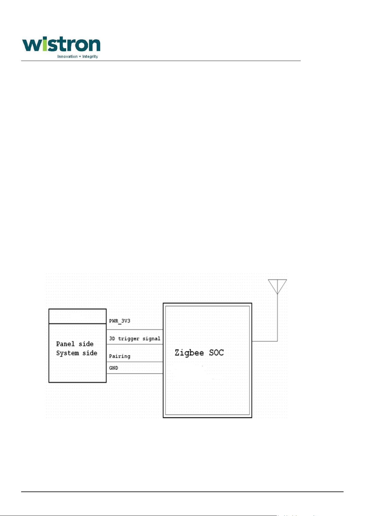
3D system
RF IC
Microprocessor.
Trigger signal.
2.4G RF circuitry
Power:
3.3V power source.
3D RF Tx Dongle Specification
Connector:
USB 2.0 type A connector: System power source and 3D trigger signal.
Electronics module:
Microprocessor.
Trigger signal.
2.4G RF circuitry
Power:
5V power source
1.3.2 Hardware Block Diagram
3D RF Tx Module Block Diagram
Page 6 27 October 2011
Page 8
. Wistron 3D RF Tx Module and Tx Dongle
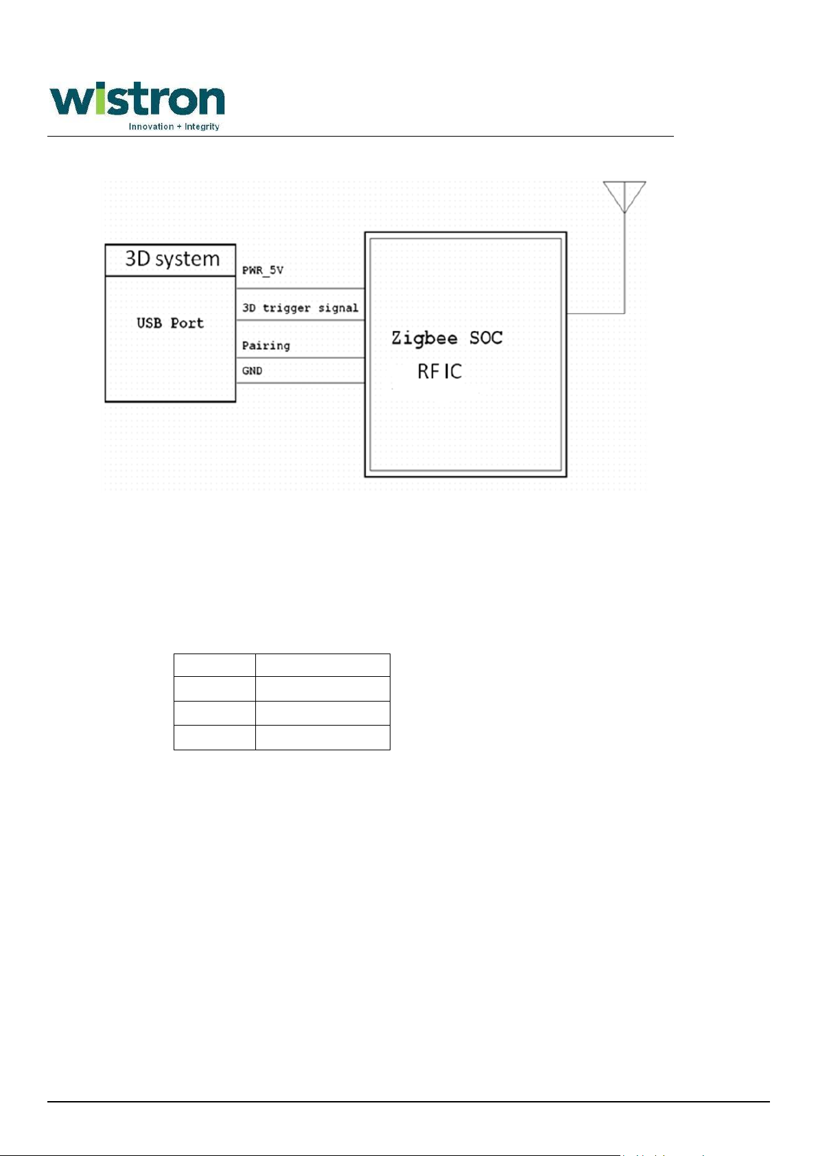
Pin1
3.3V
Pin2
3D trigger signal
Pin3
paring
Pin4
GND
3D RF Tx Dongle Block Diagram
1.3.3 Subsystem
3D RF Tx Module
Connector:
4 pin connector: System power source and 3D trigger signal.
Electronics module:
Microprocessor.
There shall be GPIO that is used to trigger 3D signal.
Immediately via 2.4G RF wireless output the 3D signal to radio.
Firmware and paring ID upgrades support.
Trigger signal.
Voltage : 3.3V +- 5%
Pulse
2.4G RF circuitry
Connectivity supporting: frequency hopping with 3 channels.
RF performance: 10 meters
1 3D RF Tx module can support up to 10 3D RF Rx module at one time
Page 7 27 October 2011
Page 9
. Wistron 3D RF Tx Module and Tx Dongle
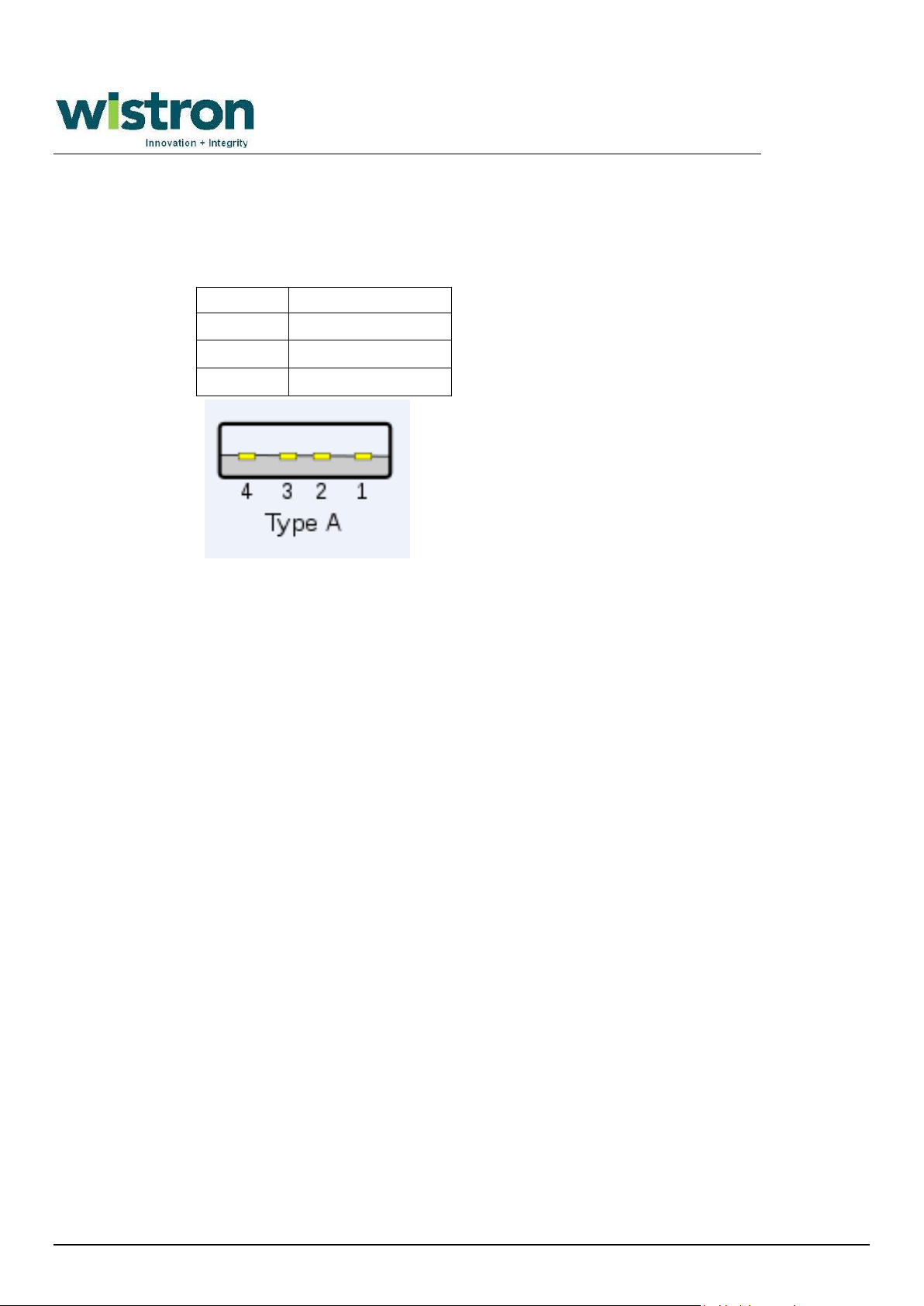
Pin1
5V
Pin2
3D Trigger Signal
Pin3
Paring
Pin4
GND
3D RF Tx Dongle
Connector:
USB 2.0 type A connector: System power source and 3D trigger signal.
Electronics module:
Microprocessor.
There shall be GPIO that is used to trigger 3D signal.
Immediately via 2.4G RF wireless output the 3D signal to radio.
Firmware and paring ID upgrades support.
Trigger signal.
Voltage : 3.3V +- 5%
Pulse
2.4G RF circuitry
Connectivity supporting: frequency hopping with 3 channel
RF performance: 10 meters
1 3D RF Tx dongle can support up to 10 3D RF Rx module at one time
Page 8 27 October 2011
Page 10
. Wistron 3D RF Tx Module and Tx Dongle
Description
Q'ty
Remark
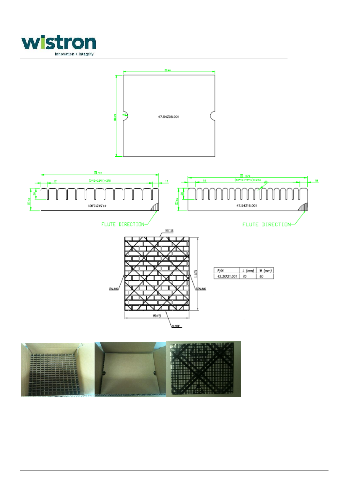
CTN AB B/R 323*290*136MM
0.0028
350 pcs in 1 carton
PAD B 310*275MM
0.0085
PARTITION B 312*52MM
0.0966
PARTITION B 279*52MM
0.6818
BAG CONDUCTIVE GRID 70*60MM
1
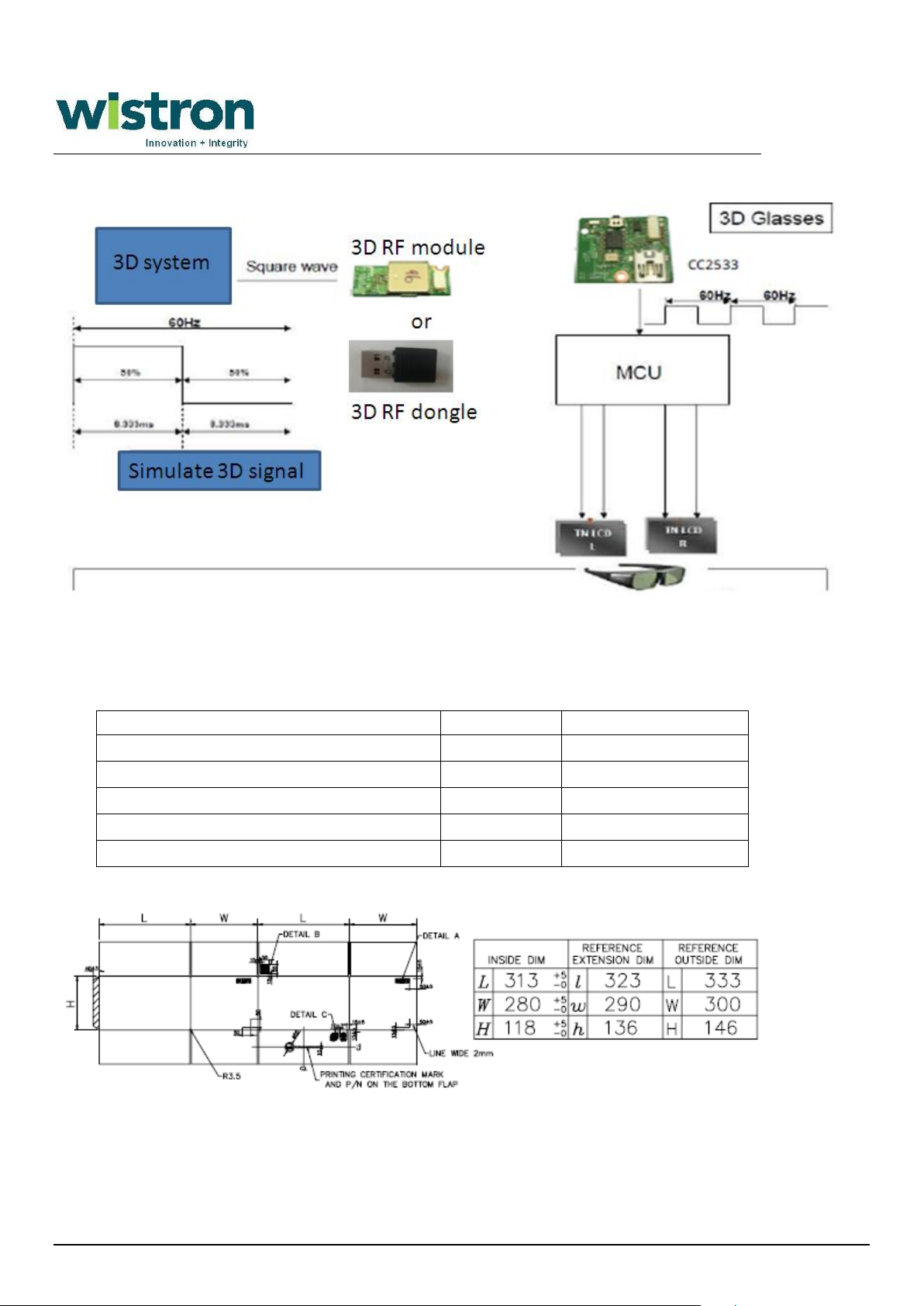
‧1.4 Operational Concept
1.5 Packing
3D RF Tx Module and 3D RF Tx Dongle Packing Material
Page 9 27 October 2011
Page 11
. Wistron 3D RF Tx Module and Tx Dongle
Packing photo
2 Reliability
2.1 Purpose
To insure the quality of Wistron 3D radio frequency product which developed, designed and
Page 10 27 October 2011
Page 12
. Wistron 3D RF Tx Module and Tx Dongle
Test item
Condition
1000mm for 1 worse case of concer 3 edges
cartons damage.
9 Antenna Performance Test
in band (2400~2483.5MHz)
- antenna efficiency
- Antenna Return loss
7 ESD Test
2 Cold and hot start Test
Cold start: Temp:0C, 5 times
Warm start: Temp:40C, 5 times
3 Climatic tests on non-packed product
(testing under non-operation)
–Cyclic humidity test
–Damp heat steady state test
–Dry heat test
–Cold test
4 Package Vibration Test
X,Y axis Test Time: 30 minutes
Random Vibration:Grms =1.04
8 RF Performance Test
RF performance-conductive & air test
10 EE Basic Function Test
Test coverage:
- Quick Scan
- System All Clock Check
- RF function
- DC Distribution At Device Power Line
- System Power consumption
- Room temperature System Long Run
- TX USB dongle - detect and remove on NB 20 times
1 Operation Temp/Hum Cycle Test
Temp: 0~40C, Humidity: 90%, Test duration : 24hrs
Follow up CE standard
Air Con Require
±8kV ±4kV Normal performance within the specification limits (B)
5 Package Drop Test
6 EMI Test
12 Button Test (Tx dongle)
Pairing mode by manual - 100 times
11 Angles of receive signal
Different angles from Tx or Tx dongle by 360 degrees
13 USB
15 FW & ID reflash
- Follow reflash SOP
14 RF performance
- Paired glasses and device distance 10M
- 1 Tx to 10 Rx and distance 10M
Power switch Button:20000times
16 Button and Switch Life Test
(only for Tx USB dongle paring button)
17 Tx Dongle Connector Life Test
Plug in and out system for 2000 times
produced meet requirements of customers.
2.2 Scope
This document defines an applicable set of tasks necessary for an effective 3D RF Tx module and 3D RF Tx
dongle verification qualification program.
2.3 Testing Condition
Page 11 27 October 2011
Page 13
Country logo Standard
FCC pasrt 15C
FCC ID fee
short term confidentiality
EN 300 440
EN 301 489-1-3
EN 62311 ( MPE)
notification 31 countries
LP0002
ID fee
China SRRC RF
Japan
Telec Telec
TW
NCC
USA
EU
CE
FCC
3 Certification
. Wistron 3D RF Tx Module and Tx Dongle
Page 12 27 October 2011
Page 14
Deral Communication Commission interference state-ment :
This equipment has been tested and found to comply with the limits for a Class B digital device, pursuant to part 15 of the FCC rules. These
limits are designed to provide reasonable protection against harmful interference in a residential installation. This equipment generates, uses and
can radiate radio frequency energy and, if not installed and used in accordance with the instructions, may cause harmful interference to radio
communications. However, there is no guarantee that interference will not occur in a particular installation. If this equipment does cause harmful
interference to radio or television reception, which can be determined by turning the equipment off and on, the user is encouraged to try to
correct the interference by one or more of the following measures:
-Reorient or relocate the receiving antenna.
-Increase the separation between the equipment and receiver.
-Connect the equipment into an outlet on a circuit different from that to which the receiver is connected.
-Consult the dealer or an experienced radio/TV technician for help.
FCC Caution
This device complies with Part 15 of the FCC Rules. Operation is subject to the following two conditions:
(1) this device may not cause harmful interference and
(2) this device must accept any interference received, including interference that may cause undesired operation
RF exposure warning: The equipment complies with RF exposure limits set forth for an uncontrolled
environment. The antenna(s) used for this transmitter must not be co-located or operating in conjunction
with any other antenna or transmitter.
You are cautioned that changes or modifications not expressly approved by the party responsible for compliance could void
your authority to operate the equipment.
 Loading...