

Page 1
Version 1.0
WISOL
page 1 of 9
Item
Vendor
Part Number
SigFox
BLE
WIFI
GPS(GLONASS)
ON semiconductor
NORDIC semiconductor
ESPRESSIF
UBLOX
AX-SFUS-1-01
nRF52832
ESP8285
UBX-G8020
User Manual of WSSFM20R2(Rev1.0)
1. Introduction
The WSSFM20R2 module is a quad mode module supporting Sigfox, BLE, WiFi and GPS.
This Module able to transmit and receive messages using the SIGFOX network.
The typical applications can be used as a low power tracking device.
The application use WIFI or GPS to determine location. It will then transmit the location information via SIGFOX.
It also will transmit other information like temperature, accelerometer, and so on.
2. Hardware Architecture:
2.1 Main Chipset Information
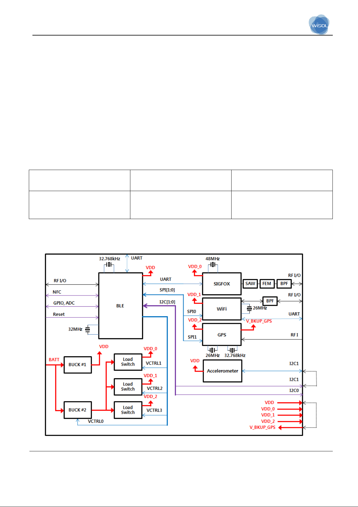
2.2 Circuit Block Diagram
The major internal and external block diagram of WSSFM20R2 is illustrated in Figure 1-1.
Figure 1-1 WSSFM20R2 block diagram and System Interface
Page 2

Version 1.0
WISOL
page 2 of 9
3. Operational Description
-SIGFOX
SIGFOX able to transmit and receive messages using the SIGFOX network.
This module address the RCZ2(North America).
-BLE
Bluetooth 4.2 optimized for low-power applications.
The RADIO contains a 2.4 GHz radio receiver and a 2.4 GHz radio transmitter that is compatible with
Nordic's proprietary 1 Mbps and 2 Mbps radio modes in addition to 1 Mbps Bluetooth® low energy mode.
-WIFI
ESP8285 implements TCP/IP, the full 802.11 b/g/n/e/i WLAN MAC protocol and Wi-Fi
Direct specification. It supports not only basic service set (BSS) operations under the distributed control function
(DCF) but also P2P group operation compliant with the latest Wi-Fi P2P protocol. Low level protocol functions
are handled automatically by ESP8285.
• RTS/CTS
• acknowledgement
• fragmentation and defragmentation
• aggregation
• frame encapsulation (802.11h/RFC 1042)
• automatic beacon monitoring / scanning, and
• P2P Wi-Fi direct
Passive or active scanning, as well as P2P discovery procedure is performed autonomously once initiated by
the appropriate command. Power management is handled with minimum interaction with host to minimize active
duty period.
-GPS (GLONASS)
The application use GPS(GLONASS) to determine location. It will then transmit the location information via
SIGFOX. It also will transmit other information like temperature, accelerometer, and so on.
3.1 Features
- SIGFOX
> Sigfox up-link and down-link functionality controlled by AT commands
> Temperature sensor
> Ultra-low power consumption
Page 3

Version 1.0
WISOL
page 3 of 9
> High performance narrow-band Sigfox
- BLE
> Based on Nordic Semiconductor nRF52832 Bluetooth Smart Soc
(ARM Cortex –M4F, 512KB flash, and 64KB RAM embedded)
> Ultra-low power multiprotocol support
> BLE Wireless application
> Bluetooth specification Version 4.2 (LE single mode) compliant
> External interface: 32 GPIO pins for NFC(tag), SPI, TWI, UART, Crystal (32.768 KHz) and ADC
-WIFI
> 2.4 GHz receiver
> 2.4 GHz transmitter
> High speed clock generators and crystal oscillator
> Real-Time Clock
> Bias and regulators
> Power management
-GPS (GLONASS)
blox 8 position engine featuring: ver 2 million effective correlators
> down to 1 s acquisition time
> up to 18 Hz navigation update rate in single GNSS mode
> Supports GPS and GLONASS as well as SBAS and QZSS
> Supports u-blox’s AssistNow Online / AssistNow Offline A-GNSS services and is OMA SUPL 1.0 compliant
> Supports u-blox’s AssistNow Autonomous (no connectivity required)
> Supports crystal oscillator and TCXO
> Supports a built-in DC/DC converter and an intelligent, user configurable power management
> Supports data logging, odometer, geo-fencing, spoofing detection, and message integrity protection.
3.2 Time base of the RF frequency
-SIGFOX
For Sigfox RF frequency, a TCXO(48MHz) is a clock reference.
-BLE
Using external 32.768 kHz crystal for RTC.
The 64 MHz crystal oscillator (HFXO) is controlled by a 32 MHz external crystal.
-WIFI
The high frequency clock on ESP8285 is used to drive both transmit and receive mixers.
This clock is generated from internal crystal oscillator and external crystal. The crystal frequency is 26 MHz.
Page 4

Version 1.0
WISOL
page 4 of 9
-GPS(GLONASS)
The RTC is driven internally by a 32.768 Hz oscillator, which makes use of an external RTC crystal.
For GPS(GLONASS) RF frequency, a TCXO(26MHz) is a clock reference.
3.3 Transmission
-SIGFOX
The Tx path produces a DBPSK-modulated signal. modulate RF signal generated by the synthesizer. The
modulated RF signal is fed to the integrated RX/TX switch and antenna interface and then out of the AX-SFUS1-01.
-BLE
The RADIO contains a 2.4 GHz radio receiver and a 2.4 GHz radio transmitter that is compatible with
Nordic's proprietary 1 Mbps and 2 Mbps radio modes in addition to 1 Mbps Bluetooth® low energy mode.
-WIFI
The 2.4 GHz transmitter up-converts the quadrature baseband signals to 2.4 GHz, and drives the antenna with
a high-power CMOS power amplifier. The function of digital calibration further improves the linearity of the
power amplifier, enabling a state of art performance of delivering +19.5 dBm average power for 802.11b
ransmission and +16dBm for 802.11n transmission.
Additional calibrations are integrated to offset any imperfections of the radio, such as:
• Carrier leakage
• I/Q phase matching
• Baseband nonlinearities
These built-in calibration functions reduce the product test time and make the test
equipment unnecessary.
3.4 Receiver
-SIGFOX
The Rx path is able to receive 905.2MHz signal and the noise amplifier is built in the inside of the chip, it
amplifies the received signal by the low noise amplifier according to the receiving intensity, and the amplified
signal is converted into the digital signal through the ADC, Packets will be interpreted.
-BLE
The RADIO contains a 2.4 GHz radio receiver and a 2.4 GHz radio transmitter that is compatible with
Nordic's proprietary 1 Mbps and 2 Mbps radio modes in addition to 1 Mbps Bluetooth® low energy mode.
-WIFI
The 2.4-GHz receiver down-converts the RF signals to quadrature baseband signals and converts them to the
digital domain with 2 high resolution high speed ADCs. To adapt to varying signal channel conditions, RF filters,
automatic gain control (AGC), DC offset cancelation circuits and baseband filters are integrated within ESP8285.
Page 5

Version 1.0
WISOL
page 5 of 9
Sigfox band
Uplink(TX)
Downlink(RX)
RC2
902.1375 ~ 904.6625 MHz
905.2MHz
RC4
920.1375 ~ 922.6625 MHz
922.3 MHz
Band
Output power
Tolerance
WIFi
19.5 dBm
+ 2.5 dB
Sigfox
22 dBm
+/- 1.5 dB
BT LE
0 dBm
+/- 4.0 dB
-GPS(GLONASS)
u-blox 8 GNSS chips are single GNSS receivers which can receive and track either GPS or GLONASS signals.
By default the u-blox 8 receivers are configured for GPS, including SBAS and QZSS reception. If power
consumption is a key factor, then QZSS and SBAS should be disabled.
3.5 Product Details
-SIGFOX
> Data Modulation
-TX : DBPSK
-RX : 2GFSK
> Frequency :
-BLE
> Data Modulation : GFSK
> Frequency : 2402-2480MHz
-WIFI
> Data Modulation :
-DSSS:CCK,BPSK,QPSK for 802.11b
-OFDM:BPSK,QPSK,16QAM,64QAM for 802.11g,n (HT20)
> Frequency Range : 2412-2484MHz
-GPS(GLONASS)
> Data Modulation : BPSK
> Frequency :
-GPS : 1575.42MHz
-GLONASS : Around 1602MHz
3.6 Output Power tolerance
Page 6

Version 1.0
WISOL
page 6 of 9
B LE
SIGFOX
2.4GHz WiFi
GPS
B LE O O O
SIGFOX
O N/A
N/A
2.4GHz WiFi
O
N/A N/A
GPS
O
N/A
N/A
3.7 WSSFM20R2 Category of signal
3.8 Simultaneous transmission
4. Installation Guide
- Contents
- Installation Figure
Page 7

Version 1.0
WISOL
page 7 of 9
<Warning Statements>
FCC Part 15.19 / RSS-GEN Sec.8.4 Statements:
This device complies with Part 15 of the FCC Rules. Operation is subject to the following two
conditions: (1) this device may not cause harmful interference, and (2) this device must
accept any interference received, including interference that may cause undesired operation.
Le présent appareil est conforme aux CNR d’Industrie Canada applicables aux appareils radio exempts de
licence. L’exploitation est autorisée aux deux conditions suivantes :
(1) l’appareil ne doit pas produire de brouillage, et
(2) l’utilisateur de l’appareil doit accepter tout brouillage radioélectrique subi, même si le brouillage est
susceptible d’en compromettre le fonctionnement.
FCC Part 15.21 statement
Any changes or modifications not expressly approved by the party responsible for
compliance could void the user's authority to operate this equipment.
RF Exposure Statement
The antenna(s) must be installed such that a minimum separation distance of at least 20 cm
is maintained between the radiator (antenna) and all persons at all times. This device must
not be co-located or operating in conjunction with any other antenna or transmitter.
l'exposition aux RF L’antenne (ou les antennes) doit être installée de façon à maintenir à tout instant une
distance minimum de au moins 20 cm entre la source de radiation (l’antenne) et toute personne physique.
End Product Labeling
The module is labeled with its own FCC ID. If the FCC ID is not visible when the module is
installed inside another device, then the outside of the device into which the module is
installed must also display a label referring to the enclosed module. In that case, the final
end product must be labeled in a visible area with the following:
“Contains FCC ID: 2ABA2SFM20R2
" Contains IC: 11534A-SFM20R2
Étiquetage du produit final Le module BT111 est étiqueté avec sa propre identification FCC et son propre
numéro de certification IC. Si l’identification FCC et le numéro de certification IC ne sont pas visibles lorsque le
module est installé à l’intérieur d’un autre dispositif, la partie externe du dispositif dans lequel le module est
installé devra également présenter une étiquette faisant référence au module inclus. Dans ce cas, le produit
final devra être étiqueté sur une zone visible avec les informations suivantes :
« Contient module émetteur identification FCC ID : 2ABA2SFM20R2
« Contient module émetteur IC : 11534A-SFM20R2
Page 8

Version 1.0
WISOL
page 8 of 9
OEM Responsibilities to comply with FCC Regulations
The module has been certified for integration into products only by OEM integrators under
the following condition:
- The antenna(s) must be installed such that a minimum separation distance of at least 20
cm is maintained between the radiator (antenna) and all persons at all times.
- The transmitter module must not be co-located or operating in conjunction with any other
antenna or transmitter except in accordance with FCC multi-transmitter product procedures.
As long as the two condition above is met, further transmitter testing may not be required.
However, the OEM integrator is still responsible for testing their end-product for any
additional compliance requirements required with this module installed (for example, digital
device emissions, PC peripheral requirements, etc.).
IMPORTANT NOTE: In the event that these conditions can ’ t be met (for certain
configurations or co-location with another transmitter), then the FCC authorization is no
longer considered valid and the FCC ID can’t be used on the final product. In these
circumstances, the OEM integrator will be responsible for re-evaluating the end product
(including the transmitter) and obtaining a separate FCC authorization.
Manual Information To the End User
The OEM integrator has to be aware not to provide information to the end user regarding
how to install or remove this RF module or change RF related parameters in the user manual of the end product.
RSS-GEN, Sec. 8.3
This radio transmitter (IC: 11534A-SFM20R4, Model: SFM20R4) has been approved by Innovation, Science
and Economic Development Canada to operate with the antenna types listed below with the maximum
permissible gain and required antenna impedance for each antenna type indicated. Antenna types not included
in this list, having a gain greater than the maximum gain indicated for that type, are strictly prohibited for use
with this device.
- List of approved antennas
1) For Sigfox antenna, INNO-EL9SWS-149 or similar part manufactured by Inno-Link. Co., Ltd. (Highest
permitted antenna gain: 2.01 dBi)
2) For Wi-Fi 2.4 GHz antenna, INNO-EL9SWS-151 or similar part manufactured by Inno-Link. Co., Ltd. (Highest
permitted antenna gain: 4.15 dBi)
3) For BT LE antenna, INNO-EL9SWS-151 or similar part manufactured by Inno-Link. Co., Ltd.
(Highest permitted antenna gain: 4.15 dBi)
Le présent émetteur radio (IC: 11534A-SFM20R4, Model: SFM20R4) a été approuvé par Industrie Canada pour
fonctionner avec les types d’antenne énumérés ci-dessous et ayant un gain admissible maximal et l’impédance
requise pour chaque type d’antenne. Les types d’antenne non inclus dans cette liste, ou dont le gain est
supérieur au gain maximal indiqué, sont strictement interdits pour l’exploitation de l’émetteur.
Page 9

Version 1.0
WISOL
page 9 of 9
- Liste des antennes approuvées
1) Pour l'antenne Sigfox, INNO-EL9SWS-149 ou une pièce similaire fabriquée par Inno-Link. Co., Ltd. (Plus
haut gain d'antenne autorisé: 2,01 dBi)
2) Pour antenne Wi-Fi 2,4 GHz, INNO-EL9SWS-151 ou une pièce similaire fabriquée par Inno-Link. Co., Ltd.
(Plus haut gain d'antenne autorisé: 4.15 dBi)
3) Pour l'antenne BT LE, INNO-EL9SWS-151 ou une pièce similaire fabriquée par Inno-Link. Co., Ltd. (Plus
haut gain d'antenne autorisé: 4.15 dBi)
Antenna Installation Requirement
The host manufacturer must meet the antenna requirements stated in operational description and must not give
to access to antenna connector to user when you install this module into devices to be compliance with FCC
section 15.203.
 Loading...