

Page 1
WISOL
page 1 of 9
Item
Vendor
Part Number
Sigfox
ON semiconductor
AX-SFUS-1-01
User manual of SFM11R2D
1. Introduction
The module is a SIGFOX only module able to transmit and receive messages using the SIGFOX network.
The Sigfox chipset is from ON semiconductor, part number AX-SFUS-1-01.
2. Hardware Architecture:
2.1 Main Chipset Information
2.2 Circuit Block Diagram
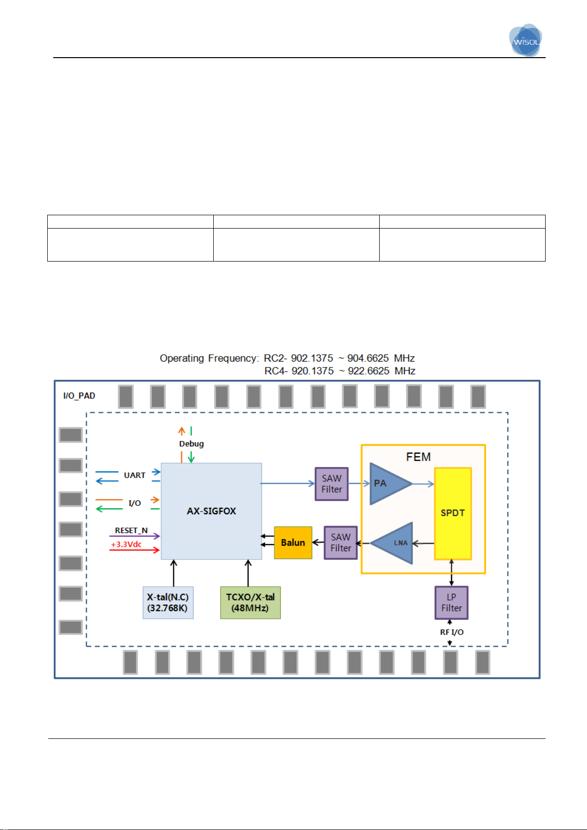
The major internal and external block diagram of Module is illustrated in Figure 1-1.
Figure 1-1 Module block diagram and Interface
Page 2

WISOL
page 2 of 9
3. Operational Description
This Module able to transmit and receive messages using the SIGFOX network.
This module addresses the RC2 and RC4 zone (North America and Australia).
- Features
> Sigfox up-link and down-link functionality controlled by AT commands
> Temperature sensor
> Ultra-low power consumption
> High performance narrow-band Sigfox
- Time base of the RF frequency
For Sigfox RF frequency, a TCXO(48MHz) is a clock reference.
- Transmission
The Tx path produces a DBPSK-modulated signal. modulate RF signal generated by the synthesizer. The
modulated RF signal is fed to the integrated RX/TX switch and antenna interface and then out of the AXSFEU-1-01.
- Receiver
The Rx path is able to receive 905.2MHz, 922.3MHz signal and the noise amplifier is built in the inside of
the chip, it amplifies the received signal by the low noise amplifier according to the receiving intensity, and
the amplified signal is converted into the digital signal through the ADC, Packets will be interpreted.
Page 3

WISOL
page 3 of 9
Sigfox zone
Uplink(TX)
Downlink(RX)
RC2(North America)
902.1375 ~ 904.6625 MHz
905.2MHz
RC4(Australia)
920.1375 ~ 922.6625 MHz
922.3MHz
- Product Details
> Data Modulation
Sigfox : TX- DBPSK
RX- 2GFSK
> Frequency :
Page 4

WISOL
page 4 of 9
Parameter
Min
Typ.
Max
Unit
RF Frequency
RC2
Tx 902.2
MHz
Rx 905.2
MHz
RC4
Tx 920.8
MHz
Rx 922.3
MHz
Tx output power(at “24” setting)
-
+22.5
+24
dBm
Frequency Error Tolerance(+25℃)
-2.5
-
+2.5
ppm
2nd Harmonics(conducted)
-
-44
-
dBm
3nd Harmonics(conducted)
-
-44
-
dBm
Rx Sensitivity(@600bps, GFSK)
-
-129
-
dBm
Rx Spurious Emission(30MHz~12.75GHz)
-54
dBm
Symbol
Parameter
Min
Typ.
Max
Unit
VDD
Power supply
2.7
3.3
3.6
V
Idd
current
-
170 - mA
Symbol
Parameter
Rating
Unit
Temp
Operating
-30 to +85
℃
TSTG
Storage Temperature
-40 to +125
℃
- Product Spec.
- Product pwr Spec.
- Product Temp. Spec.
Page 5

WISOL
page 5 of 9
4. Installation Guide
- Contents
- Installation Figure
Page 6

WISOL
page 6 of 9
5. Notice
Page 7

WISOL
page 7 of 9
<Warning Statements>
FCC Part 15.19 / RSS-GEN Sec.8.4 Statements:
This device complies with Part 15 of the FCC Rules. Operation is subject to the following two
conditions: (1) this device may not cause harmful interference, and (2) this device must
accept any interference received, including interference that may cause undesired operation.
Le présent appareil est conforme aux CNR d’Industrie Canada applicables aux appareils radio exempts de
licence. L’exploitation est autorisée aux deux conditions suivantes :
(1) l’appareil ne doit pas produire de brouillage, et
(2) l’utilisateur de l’appareil doit accepter tout brouillage radioélectrique subi, même si le brouillage est
susceptible d’en compromettre le fonctionnement.
FCC Part 15.21 statement
Any changes or modifications not expressly approved by the party responsible for
compliance could void the user's authority to operate this equipment.
RF Exposure Statement
The antenna(s) must be installed such that a minimum separation distance of at least 20 cm
is maintained between the radiator (antenna) and all persons at all times. This device must
not be co-located or operating in conjunction with any other antenna or transmitter.
l'exposition aux RF L’antenne (ou les antennes) doit être installée de façon à maintenir à tout instant une
distance minimum de au moins 20 cm entre la source de radiation (l’antenne) et toute personne physique.
End Product Labeling
The module is labeled with its own FCC ID. If the FCC ID is not visible when the module is
installed inside another device, then the outside of the device into which the module is
installed must also display a label referring to the enclosed module. In that case, the final
end product must be labeled in a visible area with the following:
“Contains FCC ID: 2ABA2SFM11R2D
" Contains IC: 11534A-SFM11R2D
Étiquetage du produit final Le module BT111 est étiqueté avec sa propre identification FCC et son propre
numéro de certification IC. Si l’identification FCC et le numéro de certification IC ne sont pas visibles lorsque le
module est installé à l’intérieur d’un autre dispositif, la partie externe du dispositif dans lequel le module est
installé devra également présenter une étiquette faisant référence au module inclus. Dans ce cas, le produit
final devra être étiqueté sur une zone visible avec les informations suivantes :
« Contient module émetteur identification FCC ID : 2ABA2SFM11R2D
« Contient module émetteur IC : 11534A-SFM11R2D
Page 8

WISOL
page 8 of 9
OEM Responsibilities to comply with FCC Regulations
The module has been certified for integration into products only by OEM integrators under
the following condition:
- The antenna(s) must be installed such that a minimum separation distance of at least 20
cm is maintained between the radiator (antenna) and all persons at all times.
- The transmitter module must not be co-located or operating in conjunction with any other
antenna or transmitter except in accordance with FCC multi-transmitter product procedures.
As long as the two condition above is met, further transmitter testing may not be required.
However, the OEM integrator is still responsible for testing their end-product for any
additional compliance requirements required with this module installed (for example, digital
device emissions, PC peripheral requirements, etc.).
IMPORTANT NOTE: In the event that these conditions can ’ t be met (for certain
configurations or co-location with another transmitter), then the FCC authorization is no
longer considered valid and the FCC ID can’t be used on the final product. In these
circumstances, the OEM integrator will be responsible for re-evaluating the end product
(including the transmitter) and obtaining a separate FCC authorization.
Manual Information To the End User
The OEM integrator has to be aware not to provide information to the end user regarding
how to install or remove this RF module or change RF related parameters in the user manual of the end product.
RSS-GEN, Sec. 8.3
This radio transmitter (IC: 11534A-SFM11R2D, Model: SFM11R2D has been approved by Innovation, Science
and Economic Development Canada to operate with the antenna types listed below with the maximum
permissible gain and required antenna impedance for each antenna type indicated. Antenna types not included
in this list, having a gain greater than the maximum gain indicated for that type, are strictly prohibited for use
with this device.
- List of approved antennas
1) For Sigfox antenna, INNO-EL9SWS-149 or similar part manufactured by Inno-Link. Co., Ltd. (Highest
permitted antenna gain: 2.01 dBi)
Le présent émetteur radio (IC: 11534A-SFM20R4, Model: SFM20R4) a été approuvé par Industrie Canada pour
fonctionner avec les types d’antenne énumérés ci-dessous et ayant un gain admissible maximal et l’impédance
requise pour chaque type d’antenne. Les types d’antenne non inclus dans cette liste, ou dont le gain est
supérieur au gain maximal indiqué, sont strictement interdits pour l’exploitation de l’émetteur.
- Liste des antennes approuvées
1) Pour l'antenne Sigfox, INNO-EL9SWS-149 ou une pièce similaire fabriquée par Inno-Link. Co., Ltd. (Plus
haut gain d'antenne autorisé: 2,01 dBi)
Page 9

WISOL
page 9 of 9
Antenna Installation Requirement
The host manufacturer must meet the antenna requirements stated in operational description and must not give
to access to antenna connector to user when you install this module into devices to be compliance with FCC
section 15.203.
 Loading...