

Page 1
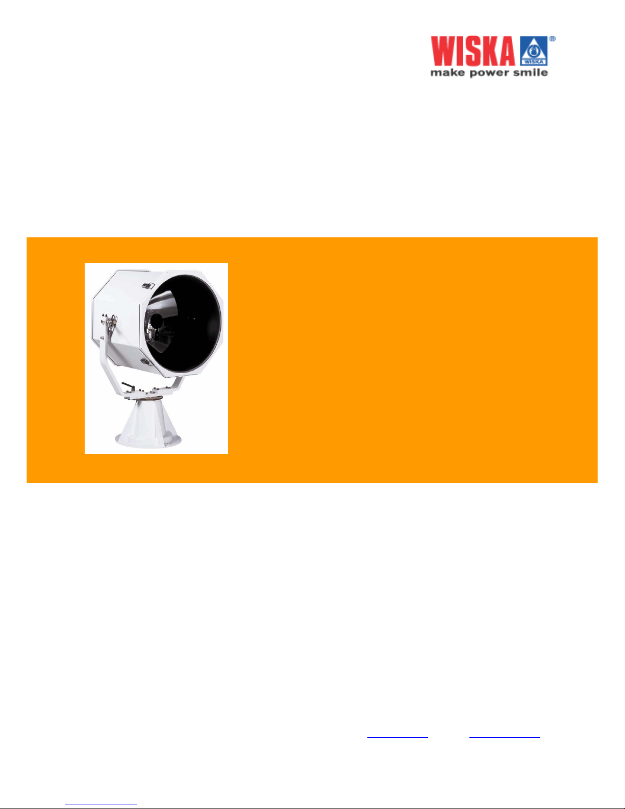
OPERATING INSTRUCTIONS
SEARCHLIGHT
SH400/575
230 V 50/60 Hz
WISKA Hoppmann & Mulsow GmbH
Kisdorfer Weg 28 • D-24568 Kaltenkirchen
Tel. +49 (0) 4191/508-100 • Fax +49 (0) 4191/508-249
Internet www.wiska.de
• E-Mail [email protected]
SH400-575 Rev.230903E
Page 2

About this manual SH400-575 Rev.230903E
2
SH400-575 Rev.230903E
Page 3

Contents
1. ABOUT THIS MANUAL ...................................................... 4
1.1 Warning symbols and markings used in this manual .... 4
1.2 Who should read this instructions ................................. 4
2. SAFETY............................................................................... 5
2.1 General information ...................................................... 5
2.2 Working with Metal Halid lamps .................................... 5
2.3 In case the lamp breaks................................................ 6
2.4 Protective measures..................................................... 7
2.5 Operating requirements ................................................ 7
2.6 Maintenance / cleaning................................................. 8
3. OVERVIEW ......................................................................... 9
3.1 Assembly drawings....................................................... 9
3.2 Technical specifications .............................................. 10
3.3 Unit nameplates .......................................................... 12
3.4 Dimensions ................................................................. 12
3.5 Circuit diagram............................................................ 16
4. INSTALLATION................................................................. 18
4.1 Unpacking the unit ...................................................... 18
4.2 Installation................................................................... 18
4.3 Electrical connections ................................................. 20
5. OPERATION...................................................................... 21
5.1 Control unit RCU......................................................... 21
5.2 Turning on the searchlight .......................................... 21
5.3 Turning off the searchlight .......................................... 22
6. MAINTENANCE ................................................................ 23
6.1 Cleaning...................................................................... 23
7. REPLACING DEFECTIVE PARTS ................................... 23
7.1 Before you begin......................................................... 23
7.2 Construction overview................................................. 24
7.3 Changing the lamp...................................................... 25
7.4 Changing the primary reflector.................................... 27
7.5 Replacing the secondary reflector .............................. 28
7.6 Replacing the ignition unit........................................... 29
8. DISPOSAL ........................................................................ 30
9. SPARE PARTS ................................................................. 31
SH400-575 Rev.230903E About this manual
3
SH400-575 Rev.230903E
Page 4
1. About this manual
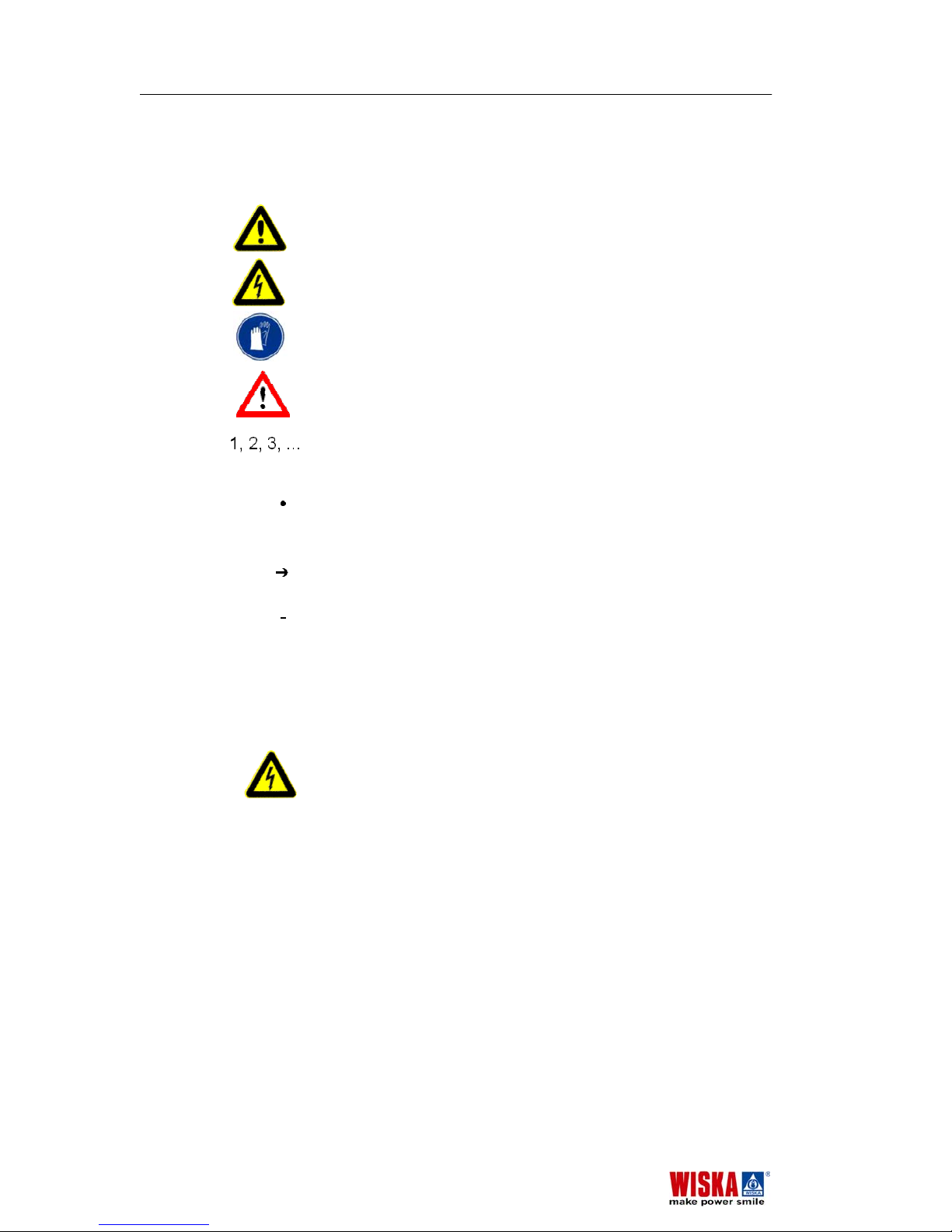
1.1 Warning symbols and markings used in this manual
Danger! Failure to observe this warning poses the risk of
personal injury or death.
Danger of electrical shock! Failure to observe this warning
poses the risk of personal injury or death from electrocution.
Gloves are recommended to fulfil this step in order to protect
yourself or the material handled
Attention! Failure to observe this precaution poses risk of
damage to environment and the product.
Operating instruction which are to be followed in a certain
order are numbered.
Operating instructions consisting of only a single step or of
steps which can be carried out in any order are set off by a
bullet point.
Confirmation messages in response to completed operation
steps are preceded by an arrow.
Listing items are preceded by a dash.
1.2 Who should read this instructions
These operating instructions are intended for all personal
assigned to install maintain and operate the searchlight.
Danger of electrical shock! All electrical work related to
installing and repairing the searchlight should only be carried
out by qualified electricians.
About this manual SH400-575 Rev.230903E
4
SH400-575 Rev.230903E
Page 5
2. Safety
Be sure to observe the following safety instructions. Failure to
do so will pose danger to yourself and others.
2.1 General information
Intended use
The searchlight SH400/575 is designed to shine a spotlight on
distant objects. The searchlight has a range of up to 3460m.
The searchlight is designed for use on ships, in particular for
polar voyages through icy waters.
Due to its high intensity, the searchlight is not to be used to
illuminate persons near the searchlight.
It is not designed for lighting rooms on the ship or in buildings.
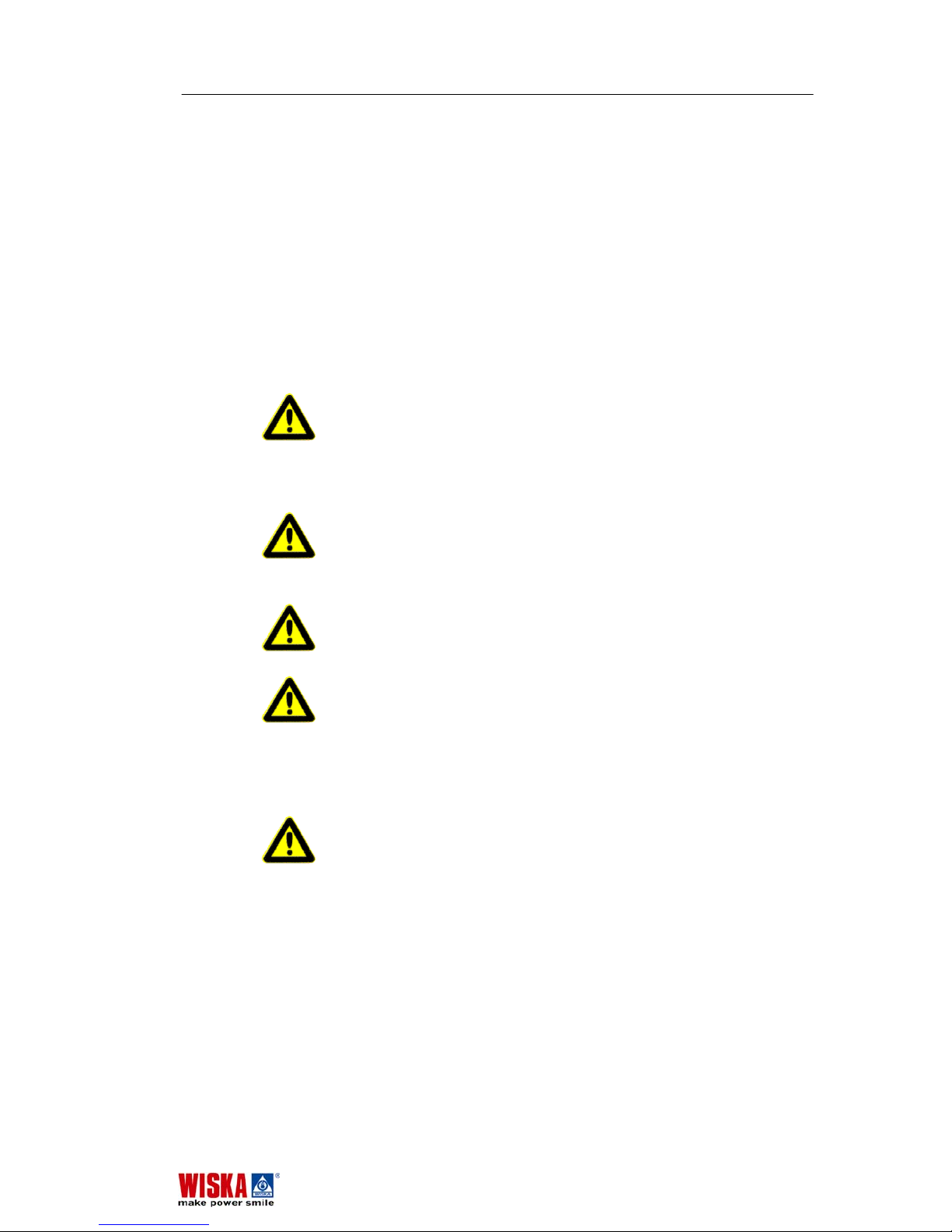
Danger! The searchlight should not be altered or modified in
any way due to the danger this poses to persons and
damages which may occur to the searchlight. Failure to
observe this will void the approval certificate.
Only original spare parts may be used.
Use of unauthorised spare parts will void any warranty.
Danger of burns! Never touch the searchlight during
operation. The housing may reach temperatures as high as
180 °C. Always allow the searchlight to cool down before
carrying out maintenance work or repairs. In case of burns,
immediately cool the burned area and get medical help.
Danger of blinding! Never look into the source of light during
operation. This poses a danger to your eyesight. Never point
the searchlight at people.
Danger of crushing! Dander of cutting! Be sure that there
are no persons directly next to the searchlight before rotating
or tilting the searchlight. Persons standing near the searchlight
may get limbs caught between the searchlight and base and
serious injuries may result.
2.2 Working with Metal Halid lamps
Danger of explosion! Metal Halid lamps carry a high internal
pressure during operation. The internal pressure during
operation may be in an extend of 200 bar.
For this reason the following safety precautions must be
observed when working with Metal Halid lamps:
SH400-575 Rev.230903E Safety
5
SH400-575 Rev.230903E
Page 6
Transport
• Always store and transport Metal Halid lamps in a way
that the glass body of the lamp can not break.
• Also, after you have replaced a defective lamp store the
used one in a safe place that it does not break.
• In case a lamp has broken follow the guidelines given in
chapter 2.3
In case the lamp breaks.
Operating the lamp
• Never touch the lamp bulb with your bare fingers. Before
mounting the lamp, remove any fingerprints smudges
using a non-abrasive, lint-free cloth and alcohol solution.
Use one way gloves to handle the bulb.
• Check the lamp for any scratches, cracks or signs of
damage. Do not use damage lamps.
Service life
Metal Halid lamps have a average life of about 750 operating
hours. The real service life depends on the relation between
duty cycle and on-time.
Disposal
Metal Halid lamps contain toxic materials such as mercury,
which are toxic for the environment and for human health. For
this reason they may be disposed only under the European
rule:
EWC-Code 2001 21 “Fluorescent tubes and other
mercury containing waste”
as hazardous waste, in Europe. They must be delivered to the
Hazardous waste disposal centres.
In other countries you must follow appropriate rules of that
country.
Metal Halid lamps may not be destroyed under any
circumstances.
Risk of health
Breathe in of mercury or mercury derivatives as dust or vapour
may seriously damage your health. Beside of breathing in
mercury can also be absorbed via your skin.
2.3 In case the lamp breaks
To minimise the risk of health in case that a lamp breaks or
explodes we recommend the following guideline
• Every person in the direct proximity should leave the room
quickly in order to avoid to inhale in mercury vapour.
• Carefully vent the room for about 20 to 30 minutes.
• After the lamp has cool down and, in any case before turn
on the searchlight again, all remainder of mercury inside
of the searchlight must be cleaned off mechanically.
Safety SH400-575 Rev.230903E
6
SH400-575 Rev.230903E
Page 7

To avoid skin contact use one-way gloves. Liquid mercury can
also be taken away with off-the shelf absorption media (based
on activated carbon).
2.4 Protective measures
Temperature
- To avoid moisture accumulation and facilitate ignition, a
minimum temperature of 6 °C inside the lamp housing is
required. To ensure that the minimum temperature is
maintained, the searchlight housing is equipped with a
thermostat- controlled heater. The heater also protect the
searchlight from freezing.
- To protect the optional drive unit from freezing, the FL51 or
FL20 pan and tilt unit can also be equipped with a
thermostat-controlled heating unit.
Attention! To ensure that the minimum temperature is
maintained during cold weather conditions:
• Keep the searchlight ready for operation by leaving the
main switch S8 in ON condition. Turn on the searchlight
only by means of the switch S1, which may be located on
the remote control unit or may exist as a separate switch.
• Do not turn on the searchlight immediately if power has
been cut off for a prolonged period of time while the
temperatures were at 6 °C or less. First, place the
searchlight in standby mode by switch S8 and wait until
the minimal internal operating temperature has been
reached inside the housing.
Radiation/ Emission of dangerous particles
- Metal Halid lamps emit UV light which is hazardous to your
eyes. The special design of the searchlight prevent direct
eye contact with the arc searchlight.
- If a Metal Halid lamp should explode during operation, the
robust housing will stay intact and prevent hot glass
shards from being expelled.
2.5 Operating requirements
Protection Class
The searchlight, power supply unit and the optional drive unit
have an IP 56 protection class rating (dust-protected, heavy
seas and powerful water jets). To maintain this protection
class, all electrical cables may only be led in through
appropriate screw- connected cable fittings.
Requirement for placement
Where to install
- the searchlight: under normal operating conditions the
SH400-575 Rev.230903E Safety
7
SH400-575 Rev.230903E
Page 8

housing of the searchlight will reach temperatures up to
180 °C. Mount the searchlight only in an environments
which can resist this heat. To rule out all potential danger:
do not store any explosive or easily inflammable materials
in the immediate area of the searchlight. Such materials
include gasoline, paper and paint.
- The power supply unit PSUH: Install the PSUH at a cool
place which is not exposed to direct sunlight, vented hot
air or other dissipated heat from fuel tanks
Attention! The searchlight and power supply unit PSUH are
operating under high voltage. To prevent electromagnetic
interference with the compass, make sure an appropriate
distance is maintained between the searchlight, the power
supply unit PSUH and the compass. Also, do not run cables in
the direct proximity of the compass.
2.6 Maintenance / cleaning
Before carrying out maintenance or cleaning work:
• Turn off the main switch.
• Make sure the entire electrical system is dead.
• Wait until the searchlight has cooled down.
Safety SH400-575 Rev.230903E
8
SH400-575 Rev.230903E
Page 9
3. Overview
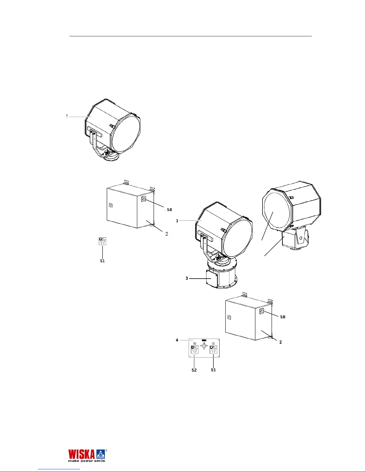
3.1 Assembly drawings
Basic configuration
Configuration with drive unit FL51
and FL20 and with remote control unit
RCU
1 Searchlight
2 Power supply unit PSUH
3 Drive unit FL51
4 Control unit RCU for FL51 /FL20
S1 ON/OFF switch for searchlight
S8 Main power switch
S2 ON/OFF switch for drive unit
5 alternative drive unit FL20
1
5
SH400-575 Rev.230903E Overview
9
SH400-575 Rev.230903E
Page 10
3.2 Technical specifications
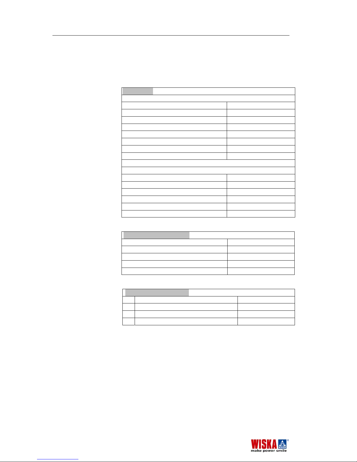
Type SH400/575, FL51 230 V 50/60 Hz
Manufacturer WISKA Hoppmann & Mulsow GmbH
Searchlight
Lamp:
Type of lamp Metal Halid lamp
Illumination 12 Mio. cd
Range 3460 m
Diffusion angle 6 ° I/10
Lamp power 575 W
Average service life of lamp 750 h
Glass parabolic reflector 400 mm
Secondary reflector 100 mm
Fixed focus
Housing:
Material steal 1.4301
Colour RAL 9016
Diameter 472 mm
Depth 505 mm
Weight 25,5 kg
Protection class IP 56
Power supply unit PSUH
Supply voltage 230 V 50/60 Hz
Fuse 16 A
Dimensions w/d/h 330 x 355 x 225
Weight 20 kg
Protection class IP 54
Lamp ignition sequence
1. Developing of ignition voltage on power ON
2. Warm up ca. 45 seconds
3. Restrict current consumption while operating
4. Reignition without cooling period immediate
Overview SH400-575 Rev.230903E
10
SH400-575 Rev.230903E
Page 11
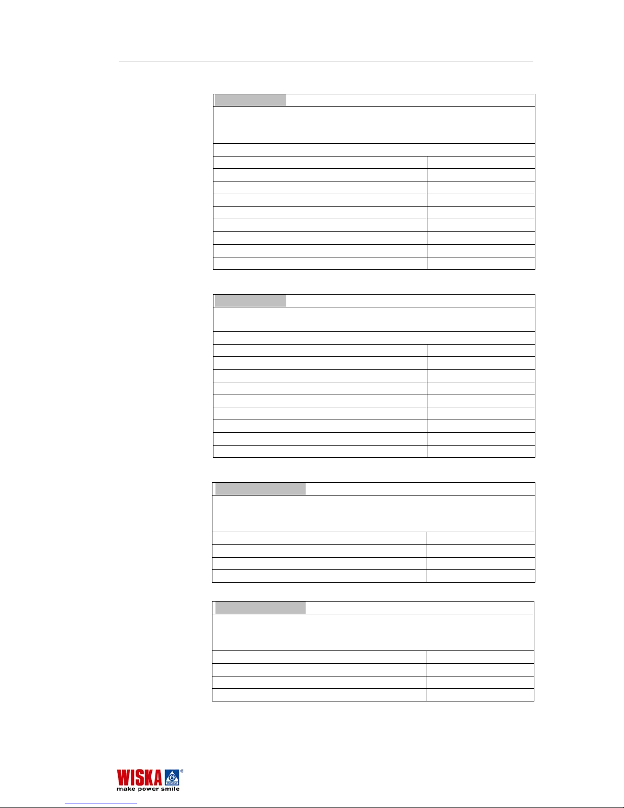
Drive unit FL51
Rotation and tilt drive unit made of salt water-resistant cast
aluminium with stainless steel grips to hold and operate the
searchlight.
Standby heater
Power cable 3 m
Power consumption 280 W
Horizontal rotation 360°; 12,8°/s
Vertical tilt +20°...-30°; 2,7°/s
Height of drive unit with search unit ca. 968 mm
Base plate diameter 360 mm
Weight 29,8 kg
Protection Class IP 56
Colour RAL 9016
Drive unit FL20
Rotation and tilt drive unit made of salt water-resistant cast
aluminium with adapter plate to hold and operate the searchlight.
Standby heater optional
Power cable 3 m
Power consumption 50 W
Horizontal rotation 330°; 5°/s
Vertical tilt +25°, 2,4°/s
Height of drive unit with search unit ca. 736 mm
Base plate diameter 120 mm
Weight 13,8 kg
Protection Class IP 67
Colour RAL 9016
Control unit RCU-E
Remote control with ON/OFF switch for searchlight and drive unit,
position control switch (joystick) and indicator lamps for installation
in a control panel.
Front 120 x 200 mm
Height + Joystick 90 x 170 mm
Weight 2,1 kg
Protection class IP 23
Control unit RCU-A
Remote control with ON/OFF switch for searchlight and drive unit,
position control switch (joystick) and indicator lamps for wall mount
installation.
Front 200 x 200 mm
Height + Joystick 80+ 85 mm
Weight 2,5 kg
Protection class IP 23
SH400-575 Rev.230903E Overview
11
SH400-575 Rev.230903E
Page 12
3.3 Unit nameplates
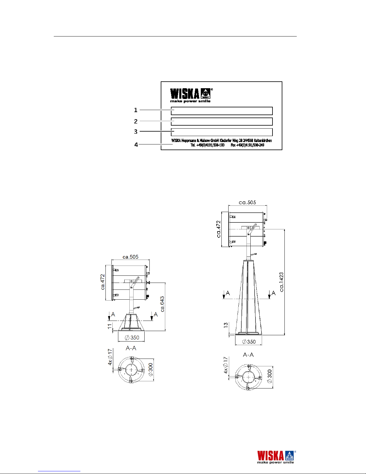
Nameplate
1 Product designation
2 Product specification
3 Product serial number
4 Manufacturer
3.4 Dimensions
Searchlight with foot and on a column
If the searchlight is equipped with the lamp
focus adjustment its depth is about 511 mm
instead of 505 mm.
Overview SH400-575 Rev.230903E
12
SH400-575 Rev.230903E
Page 13
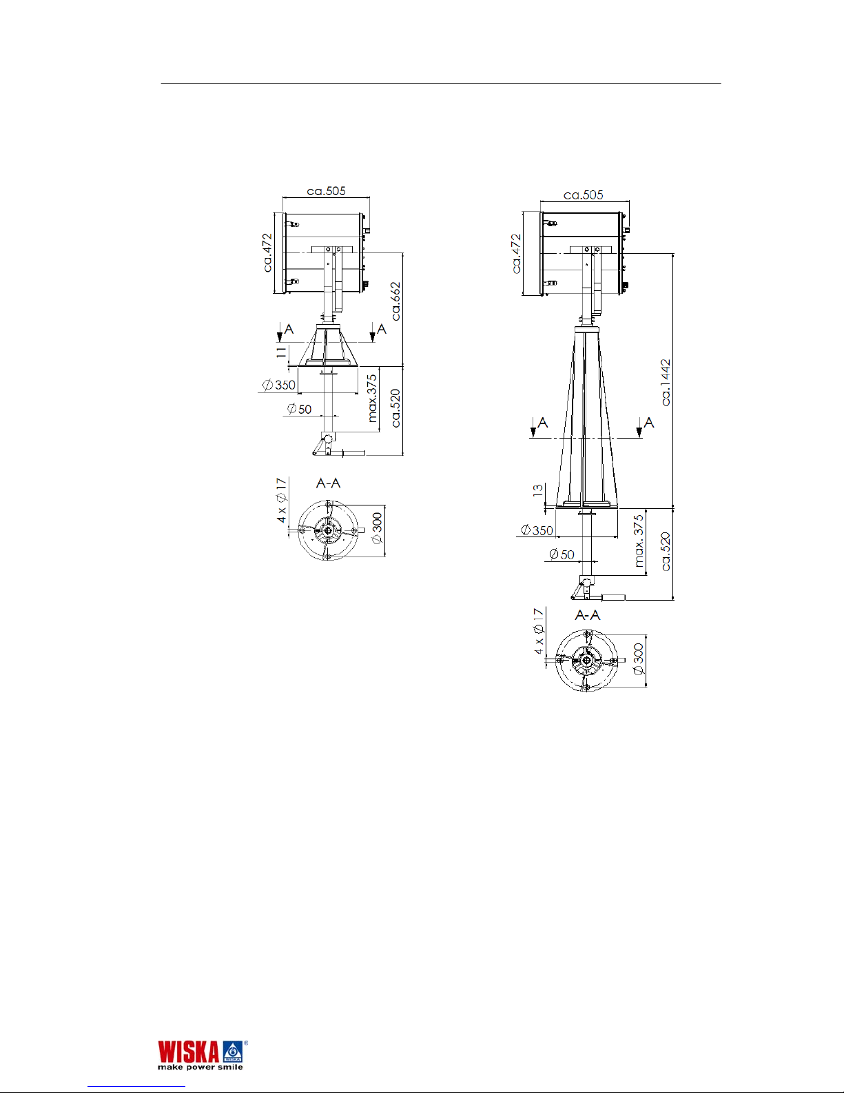
Searchlight with foot and on a column with internal mechanical
operation
If the searchlight is equipped with the lamp
focus adjustment its depth is about 511 mm
instead of 505 mm.
SH400-575 Rev.230903E Overview
13
SH400-575 Rev.230903E
Page 14
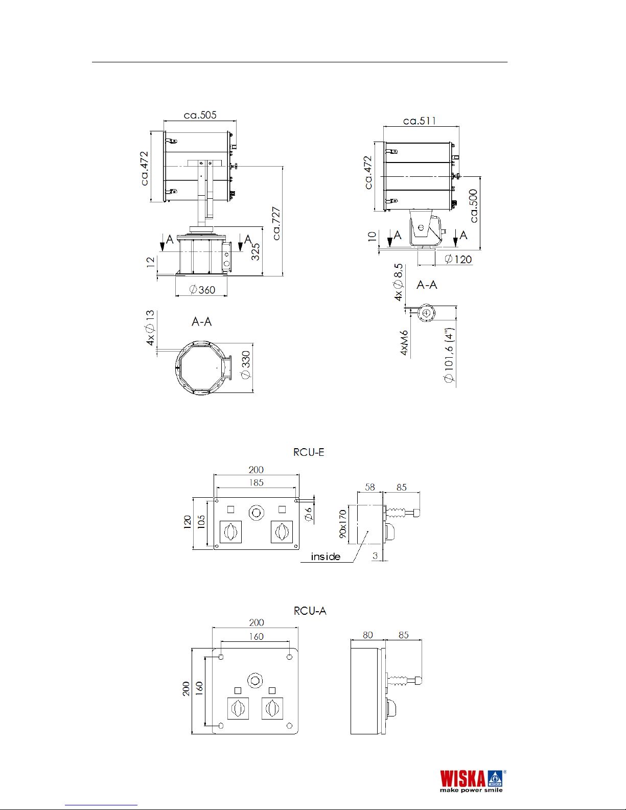
Searchlight with drive unit FL51 and FL20
Remote control unit RCU
If the searchlight is equipped
with the lamp focus adjustment
its depth is about 511 mm
instead of 505 mm.
Overview SH400-575 Rev.230903E
14
SH400-575 Rev.230903E
Page 15
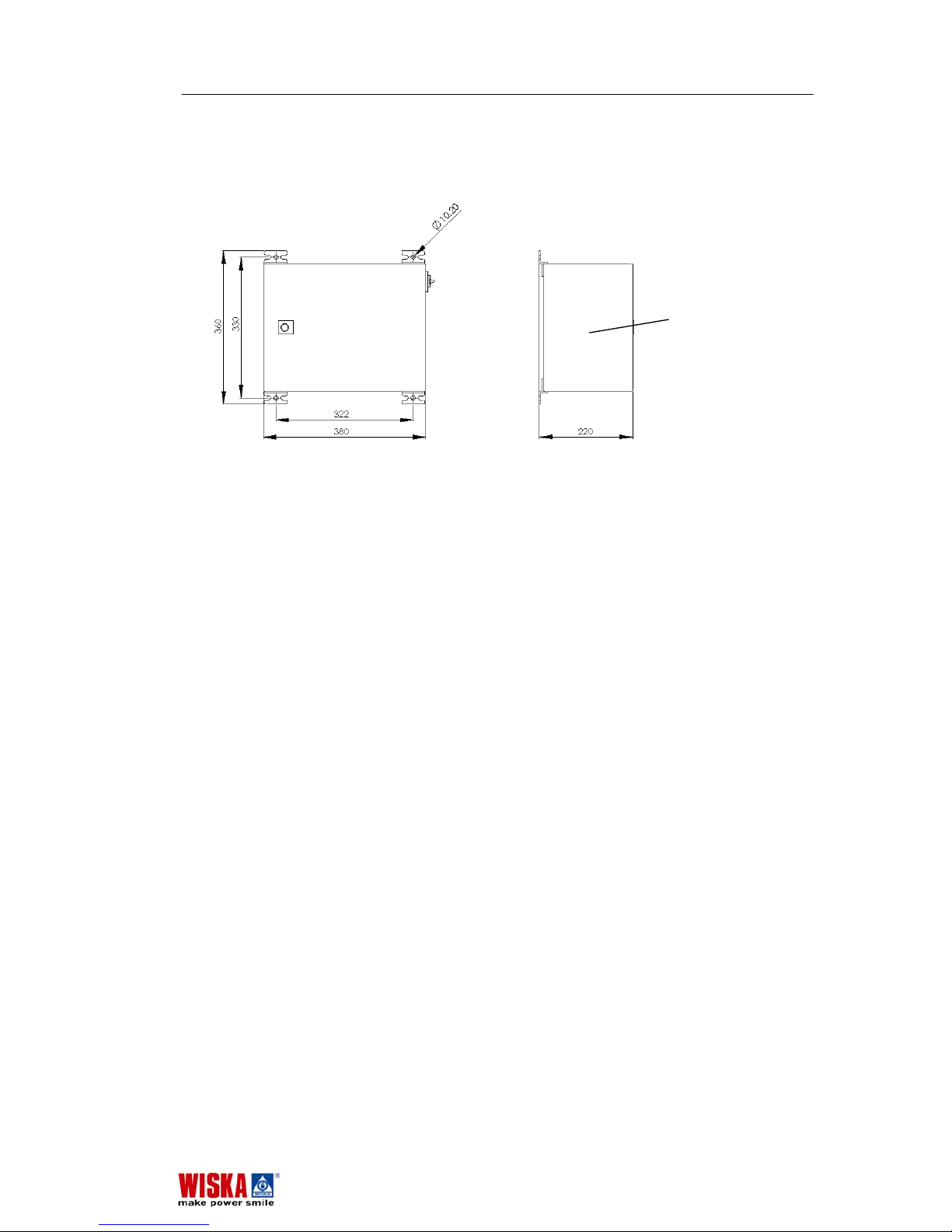
Power supply unit PSUH
inside
SH400-575 Rev.230903E Overview
15
SH400-575 Rev.230903E
Page 16
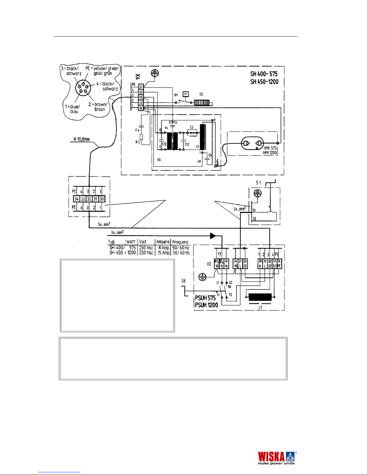
3.5 Circuit diagram
Warning! If the searchlight and the optional drive unit is switched off, the STANDBY-HEATER is still UNDER
POWER !!!
Bei abgeschaltetem Scheinwerfer und Getriebe steht die STILLSTANDHEIZUNG WEITER UNTER
SPANNUNG !!!
Flexible cables should be used to connect SW.. and FL51.
Zum Anschluss von SW.. und FL51 flexible Kabel benutzen.
A
3 Ignitionunit, Zündgerät
B1 Thermostat for Heater, Heizungsthermost
a
C4 Booster condenser,
Boosterkondensatoren
E2 Standby heater, Stillstandheizung
E3 Sparc gap, Funkenstrecke
F2 Main fuse, Hauptsicherung
L1 Choke, Drosselspule
R3 Booster resistor, Boosterwiderstand
S1 Searchlight switch, Scheinwerferschalter
S8 System main switch, System Hauptschalt
e
X… Terminal blocks, Klemmleisten
nicht im Lieferumfang enthalten
not part of delivery
Principle diagram after drawing Nr.: W 03- 032 of 30.06.03
Overview SH400-575 Rev.230903E
16
SH400-575 Rev.230903E
Page 17
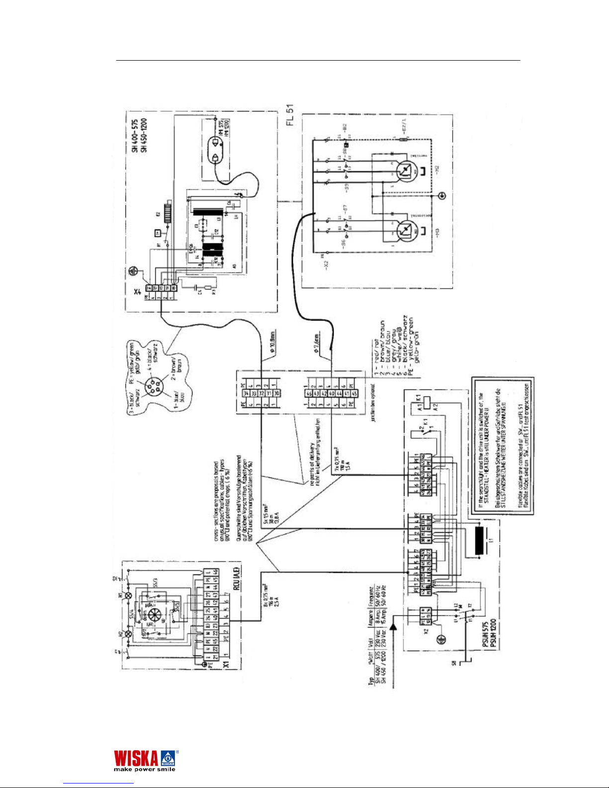
Circuit diagram with drive unit and Remote control
SH400-575 Rev.230903E Overview
17
SH400-575 Rev.230903E
Page 18

4. Installation
4.1 Unpacking the unit
Check that all parts have been included in the package. Do
not operate the searchlight if there has been damage during
transportation or parts are missing. Please contact your
WISKA agent or our distribution partner in your country. You
will find the address on the back of these operating
instructions or go to www.wiska.de
.
Remember to protect the environment and recycle the
packaging.
4.2 Installation
Installing the searchlight with FL51 drive unit
If your searchlight was ordered with its electromechanical
drive unit FL51 the searchlight comes pre-assembled on the
FL51 drive unit.
At least two persons are required for installation due to the
weight of the searchlight.
1. Drill four holes along a ø 330 mm circle in diameter. For
more information see chapter 3.4
Dimensions.
2. Place the drive unit at desired location and tighten screws.
3. Connect earth cable.
Installing the searchlight with FL20 drive unit
If your searchlight was ordered with its electromechanical
drive unit FL20 the searchlight comes also pre-assembled with
the FL20 drive unit.
At least two persons are required for installation due to the
weight of the searchlight.
1. Drill four holes along a ø 101,6 mm circle in diameter. For
more information see chapter 3.4
Dimensions.
2. Place the drive unit at desired location and tighten screws.
3. Connect earth cable.
Installing the searchlight on a low base or a column
As an alternative, the searchlight can be mounted on a low
base or a column.
At least two persons are required for installation due to the
weight of the searchlight.
1. To mount it, four holes have to be drilled in a circle of ø
300 mm in diameter, see chapter 3.4
Dimensions.
2. Place the drive unit at desired location and tighten screws.
3. Connect earth cable.
Installation SH400-575 Rev.230903E
18
SH400-575 Rev.230903E
Page 19

Installing on a low base or a column equipped with
internal mechanical operation
As an option the configuration with low base or column can be
equipped with an additional internal mechanical operation.
The mechanical linkage runs in an internal pipe of the low
base or column. Consequently the pipe must be brought
down. To do so, an additional hole for the ø 50 mm pipe has
to be drilled in the middle of the ø 300 mm circle.
See also chapter 3.4
Dimensions.
Installing the remote control unit RCU
If the searchlight is equipped with an electromechanical drive
unit, a remote control unit is required also.
The control unit is available as panel mount unit RCU-E and
as wall mount unit RCU-A. Electrically and functionally both
units are identical.
To install the units drill the required holes and make opening
if required as shown in chapter 3.4
Dimensions.
Be sure to provide wire of sufficient size (cross-section) for the
cable length.
Installing the power supply unit PSUH
At least two persons are required for installation due to the
weight of the PSUH.
Be sure to observe the instructions in chapter 2.4
Operating
requirements
on where to install the power supply unit.
The Power supply unit comes with four brackets for wall
mounting.
The searchlight and the drive unit come with a 3 m power
cable. If the PSUH is installed farther away from the
searchlight, bear in mind that the supply voltage for the PSUH
must be 230 V.
Installing the remote control unit RCU
If the searchlight is equipped with an electromechanical drive
unit, a control unit is required also.
The control unit is available as panel mount unit RCU-E and
as wall mount unit RCU-A. Electrically and functionally both
units are identical.
To install the units drill the required holes and make opening
if required, as shown in chapter 3.4
Dimensions.
Be sure to provide wire of sufficient size (cross-section) for the
cable length.
SH400-575 Rev.230903E Installation
19
SH400-575 Rev.230903E
Page 20
4.3 Electrical connections
Danger of electrical shock! Electrical connections may only
be completed by qualified personal. Be sure the power cord is
dead and nobody can accidental resume the power supply
during installation!
The circuit diagram is enclosed separately or you find it in
chapter 3.5
Diagram.
Connected load values
Supply voltage: 230 V, 50/60 Hz.
Unit Fuse: 1 x 16A included.
Waterproof (IP56) installation of all cables
1. Unscrew the cover on the underside of the PSUH power
supply unit and remove.
2. Drill holes matching the cable size and insert cable fittings
into holes.
3. Feed cable through the cable fittings and fasten firmly.
Attention! To ensure that the protection class IP56 is
maintained:
The cable sheathing must have a waterproof seal: pull the
fittings firmly into place so that the seals are wrapped tightly
around the cable fitting!
4. Connect cables in accordance with the circuit diagram
(see separate circuit diagram or chapter 3.5
Circuit
diagram).
Note: The cable from the searchlight and FL51 drive unit can
be connected directly to the power supply unit (PSUH) or via a
junction box.
Power supply
• Be sure to observe any applicable international or local
country regulations! Connect to the power supply while
ensuring reverse polarity protection!
Before first use:
• Check that installation has been carried out correctly.
Wrong connections may destroy the searchlight unit as
well as the Metal Halid lamp.
• Check to be sure that grounding and zero current works
properly!
• Reinsert fuses.
Installation SH400-575 Rev.230903E
20
SH400-575 Rev.230903E
Page 21
5. Operation
Further on, operation will described together with the electromechanical drive unit FL51 an its remote control unit RCU.
If your configuration is not equipped with such operating
features you should have a special attention to the following
points:
- To direct the searchlight, only use the appropriate
handles. Do not touch the housing of the searchlight
during operation, - Danger of burns!
- Ensure that at power on and during operation nobody is in
front of the searchlight, - Danger of blinding!
- Switch S1 to turn on the searchlight as described in
chapter 5.2 is a separate switch in your configuration and
is not located in the RCU. Because there is no electromechanical drive unit, switch S2 and the joy stick are not
available.
- Continue reading with chapter 5.2 Turning on the
searchlight
.
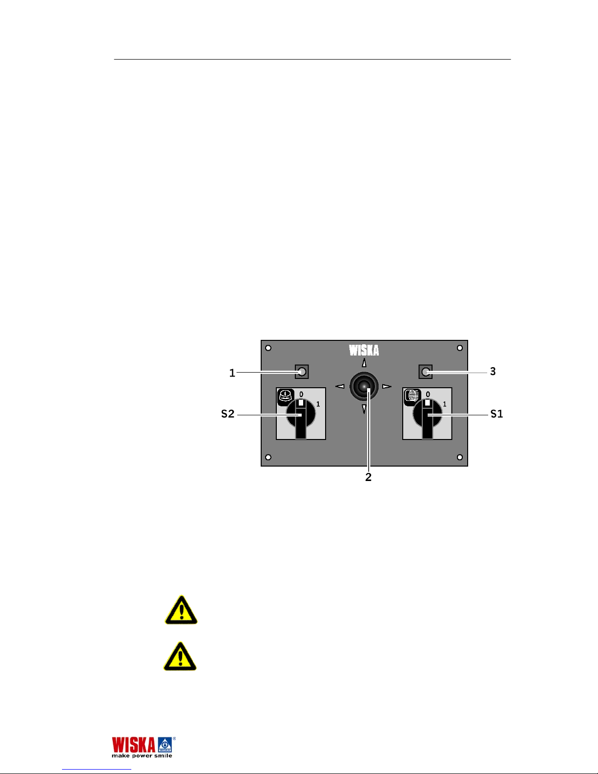
5.1 Control unit RCU
1 Drive unit indictor lamp
S2 ON/OFF switch for drive unit
2 Joystick for drive unit
S1 On/off Switch for Searchlight
3 Searchlight indicator lamp
5.2 Turning on the searchlight
Danger of burns! Never touch the searchlight during
operation. The housing may reach temperatures as high as
180 °C. In case of burns, immediately cool the burned area
and get medical aid.
Danger of blinding! Never look into the light source during
operation. This poses a danger to your eyesight. Never point
SH400-575 Rev.230903E Operation
21
SH400-575 Rev.230903E
Page 22
the searchlight at people. Before you turn on the searchlight
make sure that nobody is in front of the searchlight.
1. Turn the main power switch S8 on the PSUH power supply
unit to position ON. This supplies power to the searchlights
internal heating system and the heater of the optional drive
unit.
Attention! If ambient temperatures are below 6°C, wait until
housing interior has been heated to at least 6 °C before
igniting the lamp.
Before you ignite the lamp make sure that all work has been
completed and nobody is in front of the searchlight.
2. Turn on switch S1. The lamp will ignite
3. In case you operate the searchlight by means of an
electromechanical drive unit, you should turn it on with
switch S2, which is also located on the RCU. The drive
unit in now operational and can be controlled by means of
the joystick on the RCU.
→ If the lamp does not initiate or if it flashes a number of
times, there is either insufficient ignition voltage for the
lamp or the lamp is defective.
See chapter 7.3
Changing the lamp for more information on
replacing the lamp.
5.3 Turning off the searchlight
Attention! To ensure operational readiness: only turn off the
searchlight using the S1 and, if you work with an RCU, with
the S2 switch on the control unit.
Do not turn off the S8 switch on the power supply unit
because the internal heaters should stay on all the time.
Operation SH400-575 Rev.230903E
22
SH400-575 Rev.230903E
Page 23

6. Maintenance
6.1 Cleaning
Clean the front glass panel of the searchlight when required.
When cleaning, check if the fasteners are firmly in place and
check for rusting/corrosion.
No cleaning of searchlight interior is required. In the course of
use, slight discoloration of the reflector surface will occur. This
has no adverse effect on the unit and does not diminish the
power of the lamp.
Danger of blinding! Make sure that nobody can turn on the
searchlight while cleaning.
7. Replacing defective parts
7.1 Before you begin
1. Turn the main switch S8 to OFF.
2. Make sure the entire electrical system is dead and it can
not be turned on accidentally.
3. Wait until the searchlight has cooled down.
4. Read the chapter 2.2
Using Metal Halid lamps
5. Be careful when handling the Metal Halid lamp and do not
break it.
SH400-575 Rev.230903E Maintenance
23
SH400-575 Rev.230903E
Page 24
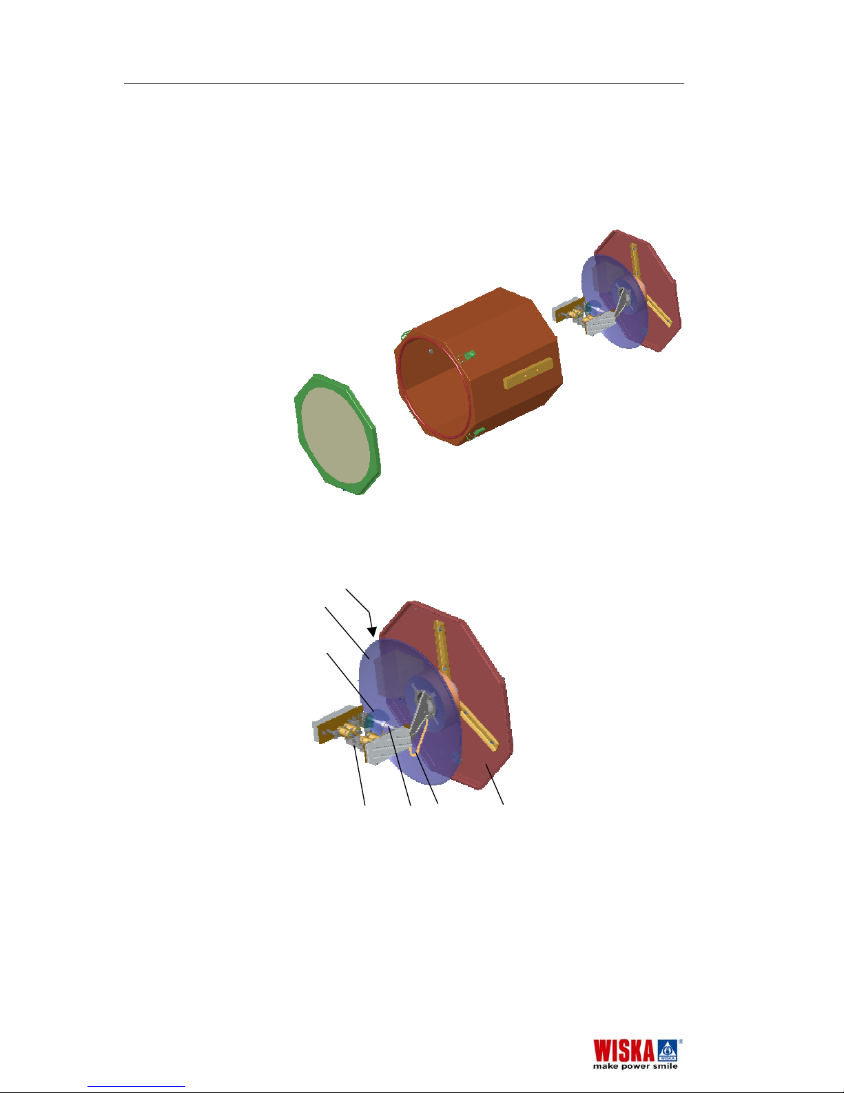
7.2 Construction overview
The following figure should help to understand the assembly of the
searchlight before you begin with replacement work.
To do the actual replacement work follow the instructions on the
following pages!
All functional components are assembled on the inside chassis
and the backplane. The inside chassis is mounted to the
backplane and can be taken out of the housing together with the
backplane.
1
Construction
2
3
4
1 Back plane
2 Inside chassis
3 Housing
4 Front panel with quick-release clamps
Inside chassis
1 Primary reflector
2 Ignition unit
3 Secondary reflector
4 Lamp carrier
5 Lamp (light source)
6 Lamp cable
7
Backplane
2
1
3
4 5 6 7
Replacing defective parts SH400-575 Rev.230903E
24
SH400-575 Rev.230903E
Page 25
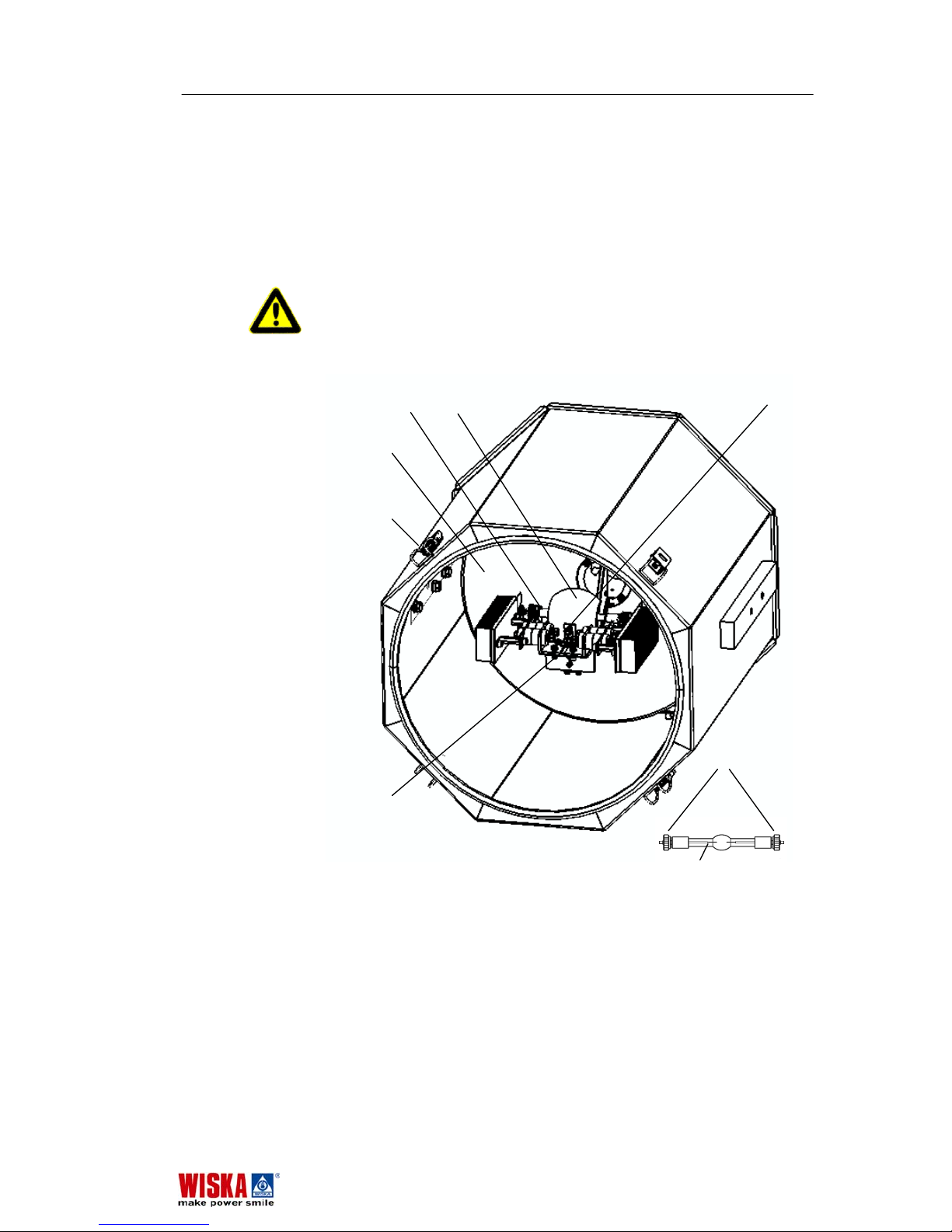
7.3 Changing the lamp
The lamp is defective if it
- only flashes a number of times without lighting up
- the lamp electrodes have burned out
- if the glass body is blackened.
Be sure to also replace the lamp if its average service life of
750 hours has been exceeded.
Danger! Any personnel carrying out repairs and maintenance
must have been properly instructed by a qualified specialist
about the dangers and required safety precautions!
Be sure to read chapter 7.1
Before you begin.
R
e
Removal:
1. Loosen the quick-release clamps 20, carefully remove
front plane and place safely out of the way.
Note: The lamp 2 is installed in the lamp carrier 1 horizontally
and is partly hidden by the secondary reflector 3. You can see
the lamp in the primary reflector 5 and observe removal and
installation in this mirror.
2. Loosen screws 8 of the defective lamp until you can lift it
1
3
20
4 2
5
8
2 3 10
5
20
8
1
SH400-575 Rev.230903E Replacing defective parts
25
SH400-575 Rev.230903E
Page 26

from its position in the lamp socket without force.
3. Put away the defective lamp without breaking it.
Attention! Should the lamp have been broken for any reason,
follow the guidelines described under 2.3
When a lamp
breaks
for the sake of your personal health and the
environment.
Installation:
Attention! Before installing in the new lamp, check it for any
fingerprint marks or damage as such as scratches and
cracking. Do not use the lamp if there are any signs of
damage. Remove any fingerprint smudges using a nonabrasive, lint-free cloth and alcohol solution.
1. Open the protective shroud of the new lamp. Be careful
not to touch the glass with your fingers. When you handle
the lamp use one-way gloves to avoid fingerprints.
2. Loosen the screws 8 far enough so you can insert the
lamp in the lamp socket 1.
3. Put the lamp in the slot of the lamp socket 1 to its rest.
4. Tighten the screws 8 in this lamp position.
5. Put the front panel back in place and close the quickrelease clamps.
6. The defective lamp must be disposed in the proper way
following the rules described in chapter 2.2
How to use
Metal Halid lamps
.
Replacing defective parts SH400-575 Rev.230903E
26
SH400-575 Rev.230903E
Page 27
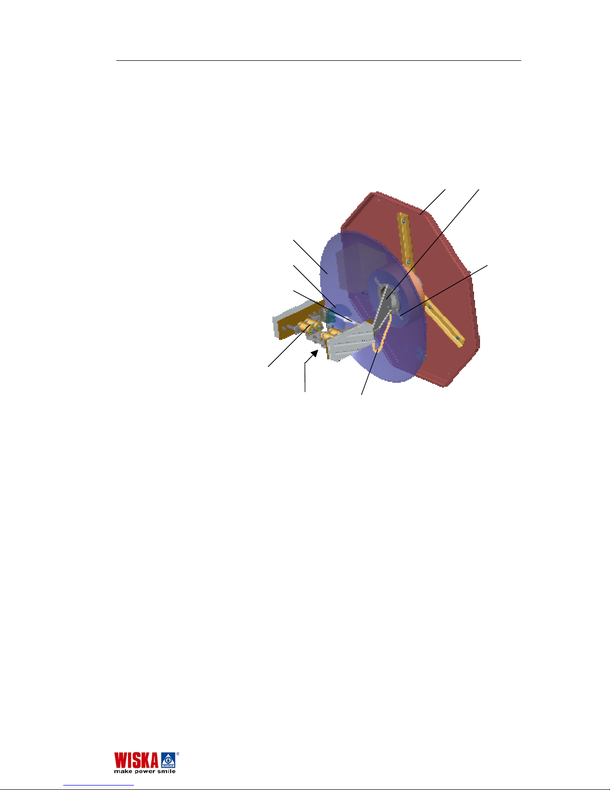
9 7
5
3 4
2
7.4 Changing the primary reflector
Danger! This repair work must be completed by a qualified
electrical technician!
Be sure to read chapter 7.1
Before you begin first.
Removal:
1. Loosen the screws on the back of the searchlight and take
out the back plane 9 together with the inside chassis.
2. Disconnect the external cable to get the assembly free.
3. Place the assembly on a safe and clean work surface.
4. Take out the lamp 2 and store it in a safe place. See
chapter
7.3 Changing the lamp.
5. Disconnect the two lamp cables 6 from the lamp carrier 1.
6. Loosen the two screws 8 underneath the lamp carrier,
which hold the lamp carrier 1 on its support 7 and take off
the lamp carrier.
7. Take off the whole lamp carrier assembly and place it out
of the way.
8. Loosen the leaf springs 4 on the reflector 5.
9. Cut open silicone seam on the back with a knife and
remove the reflector 5 from its retaining ring.
1
8 6
SH400-575 Rev.230903E Replacing defective parts
27
SH400-575 Rev.230903E
Page 28
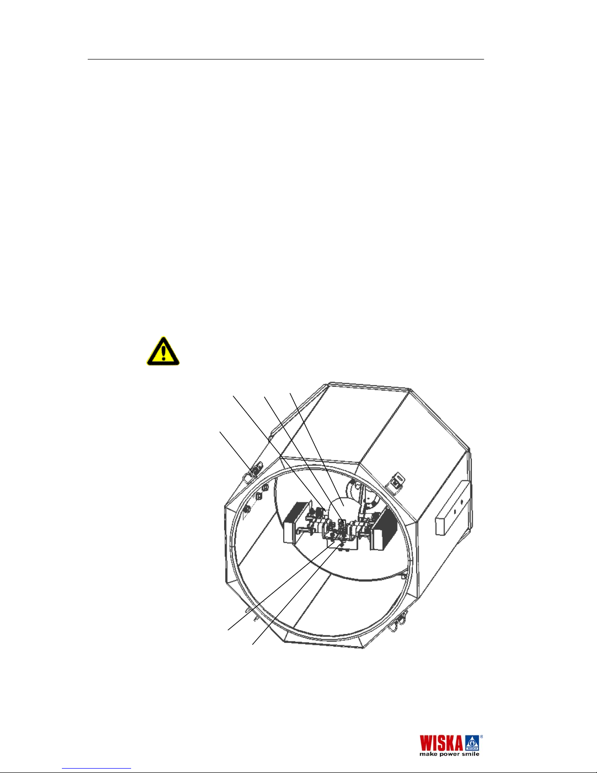
Installation:
Attention! Only use degassed silicone gel. Vapour from
silicone which has not been degassed will collect on the lamp
and destroy it.
1. Glue the new reflector onto the retaining ring using silicone
gel. Allow to dry for one day!
2. Place the reflector onto its support and re-fasten using the
leaf springs 4.
3. Check that the reflector is properly seated.
4. Take the lamp carrier and screw it back on to its support.
Be careful not to damage the new reflector!
5. Reconnect the lamp cables 6 to the lamp carrier, don’t
forget the washers.
6. Reinstall the lamp to the lamp carrier, see chapter
7.3
Changing the lamp.
7. Reconnect the external power cable.
8. Push the assembly of back plane and inside chassis back
into the searchlight housing and screw the back plane on
to it.
7.5 Replacing the secondary reflector
Danger! This repair work must be completed by a qualified
electrical technician!
Be sure to read chapter 7.1
Before you begin.
2 10 3
20
1
8
Replacing defective parts SH400-575 Rev.230903E
28
SH400-575 Rev.230903E
Page 29

Removal:
1. Loosen the quick release clamps 20 of the front plane and
put it away.
2. Take out the lamp, see chapter
7.3 Changing the lamp.
3. The secondary reflector 3 is fastened to the lamp carrier 1
with a single screw 10. Unscrew the secondary reflector
and take it out.
Installation:
1. Place the new reflector to its position on the lamp carrier.
Fasten it with screw 10.
2. Reinstall the lamp, see chapter
7.3 Changing the lamp.
3. Put back the front plane and fasten it with the quick
release clamps.
7.6 Replacing the ignition unit
Danger! This repair work must be completed by a qualified
electrical technician!
Be sure to read chapter 7.1
Before you begin.
Removal:
1. Loosen the 8 screws which hold the back plane.
2. Take out the inside chassis with the back plane from the
searchlight housing.
3. Take out the lamp and keep at on a save place.
4. The ignition unit is mounted on the back plane. To
disconnect the cables you have to disassemble the unit
from the back plane first. Loosen the three screws which
hold the ignition unit on its stand-offs.
5. To pull off the ignition unit from its position you have to
loosen one of the lamp cables on the lamp carrier and the
cable which connects to the thermostat.
6. Now, pull out the ignition unit to a more convenient
position and disconnect all cables from it. Make sure you
can reconnect them to the new ignition unit correctly, see
chapter 3.4
Circuit diagram.
Installation:
1. Take the new ignition unit and connect all cables, see
chapter 3.4
Circuit diagram.
2. Place the new ignition unit on its stand-offs and screw it
tight.
3. Reconnect the lamp cable on the lamp carrier and the
cable to the thermostat.
4. Reinstall the lamp.
5. Close the back plane.
SH400-575 Rev.230903E Replacing defective parts
29
SH400-575 Rev.230903E
Page 30

8. Disposal
Electrical parts contain toxic substances. Be sure to dispose
these components properly or send defective parts to WISKA.
The mailing address is found on the back cover of these
operating instructions.
Special care must be taken to dispose the Metal Halid lamps.
Read chapter 2.2
How to use Metal Halid lamps.
Risk of Health
Metal Halid lamps may not be destroyed in any case. Read
chapter 2.3
In case a lamp breaks.
Disposal SH400-575 Rev.230903E
30
SH400-575 Rev.230903E
Page 31
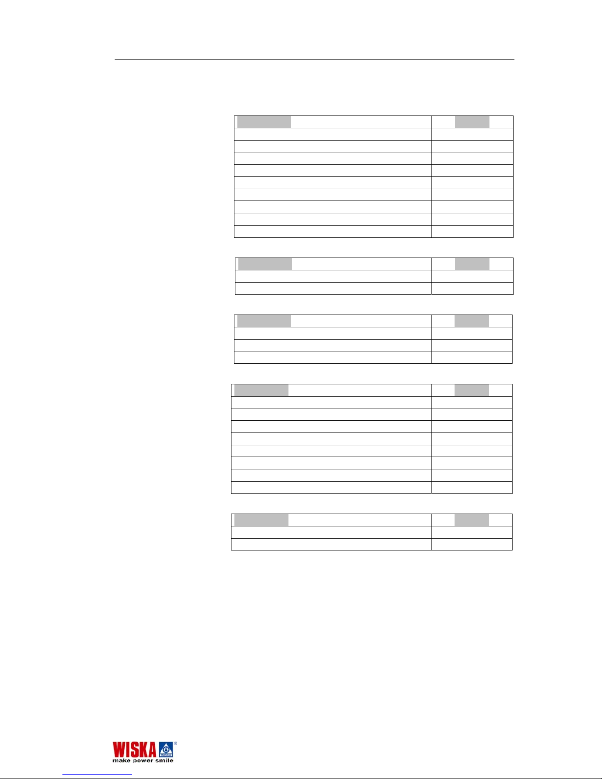
9. Spare parts
Searchlight head SH400
Designation Art. No.
Front frame + front glass 77815
Primary reflector 87080
Silicone gel 88019
Secondary reflector 87784
Metal Halid lamps 575 W 87504
SH400 lamp carrier 77285
Ignition unit type 210 87770
Standby heating unit 87276
Thermostat for standby heating unit 82174
Power supply unit PSUH
Designation Art. No.
Choke for 575W lamp 87794
Fuse 16 A 87782
Remote control unit RCU
Designation Art. No.
Position control switch (XD2-GE3) 87342
ON/ OFF Switch 87341
Lamp on indicator 87494
Drive unit FL51
Designation Art. No.
FL51 bearing kit 21015
FL51 Z hub kit 21016
Motor bearing kit 21017
Motor Z hub kit 21018
O-ring housing 85598
O-ring bearing 89013
Drive unit seal 89021
Cover for terminal box 77892
Drive unit FL20
Designation Art. No.
Tilt Motor Kit 230VAC 21581
Pan Motor Kit 230VAC 21582
All other parts should only be ordered after consulting
with WISKA sales staff.
SH400-575 Rev.230903E Spare parts
31
SH400-575 Rev.230903E
Page 32

WISKA Hoppmann & Mulsow GmbH
Kisdorfer Weg 28 • D-24568 Kaltenkirchen
Tel. +49 (0) 4191/508-100 • Fax +49 (0) 4191/508-249
Internet www.wiska.de
• E-Mail [email protected]
Please locate a Wiska representative for your country by visiting
our web-site.
 Loading...