

Page 1
- 1 -
Betriebsanleitung
Operating instructions
WISI TOPLINE HEADEND
OV 75M Grundmodul / Basic module
- Statischer / statically Remultiplexer REMUX (XX11)
2)
- Dual QAM channel transmodulator - mit/with NIT1) CS 76 (XX21)
2)
ohne/without NIT (XX31)
2)
- COFDM channel transmodulator (XX41)
2)
- Dual QAM channel transmodulator - mit/with CI, NIT, Service-Filter (X061)
2)
- Dual COFDM channel transmodulator - mit/with CI, NIT, Service-Filter (X071)
2)
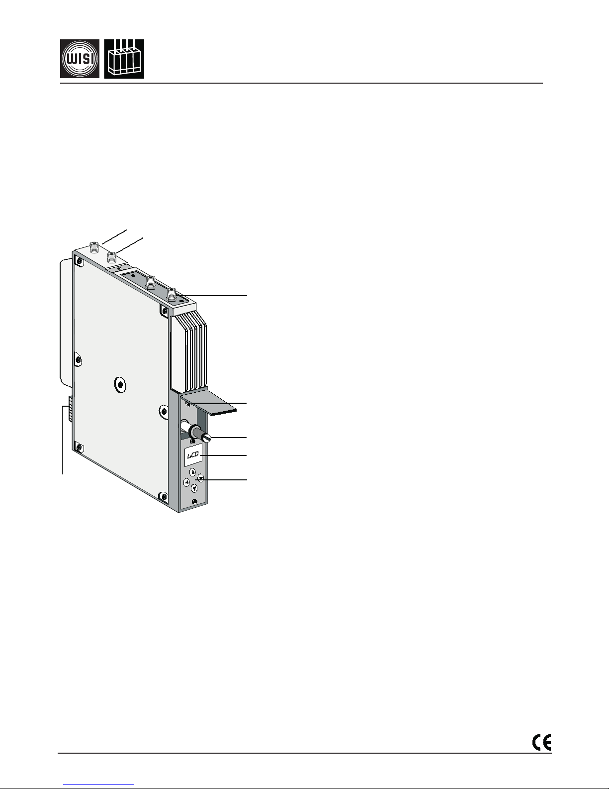
1. Durchschleifeingang F
Looped-through input F
2. Durchschleifausgang F
Looped-through output F
3. Optional / Option
abhängig vom Eingangsmodul
dep. on input module
4. Programmier-Schnittstelle
Mini-DIN
Programming interface
5. Befestigungsschraube
Fixing screw
6. Anzeige / Display
7. Bedienfeld / Control panel
8. DC-Versorgungsstecker
DC connector
2 module slots for input modules3)
- DVB-S, - DVB-S2,
- DVB-T, - DVB-C,
- Audio/Video Encoder, - ASI in-/ output,
- ASI dual input, - Fast Ethernet input (IP)
- SDI
Integrated stuffing unit for constant output data rate
Integrated transportstream (SI, NIT) handling
Output configuration loop/single switchable
Connector for remote management (OV51A / 52).
1)
256 PID filter, NIT handling, Stuffing with PCR correction
2)
Refer to ordering informations
3)
Factory setting!
3
4
5
6
7
1
2
8
2 Modulsteckplätze zur Aufnahme der Eingangsmodule3)
- DVB-S, - DVB-S2,
- DVB-T, - DVB-C,
- Audio/Video Encoder, - ASI in-/ output,
- ASI dual input, - Fast Ethernet input (IP)
- SDI
Stuffing zur Einstellung einer konstanten Ausgangs Datenrate
Transportstrom (SI, NIT) Handling
Einzel -/ Durchschleifbetrieb schaltbar
Anschluß für Remote management (OV51A / 52)
1)
256 PID-Filter, NIT-Bearbeitung, Stuffing mit PCR-Korrekt.
2)
siehe Bestellinformationen
3)
Im Werk voreingestellt!
046 319 b
Upgrade: www.wisi.de - Service - Download (password login)
Page 2
- 2 -
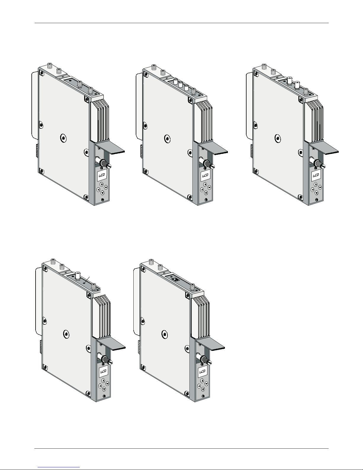
Anschlussübersicht / Connections
Kanal B
Channel
Kanal A
Channel
F-Anschlüsse / Connectors
DVB-S / DVB-S2 / DVB-T / DVB-C
Module / Modules
Audio rechts / right (rot / red)
Audio links / left (weiss / white)
Video (gelb / yellow)
Kanal A
Channel
Cinch-Anschlüsse / Connectors
AV-MPEG Modul / Module
BNC-Anschlüsse / Connectors
ASI Modul / Module
out
in
Kanal A
Channel
ASI
BNC, Klinke 3,5 mm Anschlüsse /
BNC, phone jack 3.5 mm Connectors
SDI Modul / Module
Serial Digital Video
Audio (Klinke 3,5mm
phone jack
)
Kanal A
Channel
RJ-Anschluss / Connector
IP Modul / Module
Kanal A Channel
RJ 45
Page 3

- 3 -
? ? ? ? ? ?
Signal ?
Warnhinweis
Dieses kann folgende Ursachen haben:
1. kein Eingangssignal.
2. Eingangsfrequenz falsch.
3. QPSK-Symbolrate falsch.
Inhaltsverzeichnis / Index
Beschreibung Anschlüsse / Tasten 1
- Beschreibung optionale Anschlüsse 2
Auflistung der Geräteeigenschaften 1
Werkseitige Einstellungen 1
Blockdarstellung 51-52
Bedienung Grundmodule
- Anschlussübersicht 2
- Dual QAM 4
- REMUX 5
- COFDM Remux-Mode 6-7
Hierarchical-Mode 8-9
NonHierarchical-Mode 10-11
DVB-T-Repeater-Mode 12
- Dual QAM mit CI 13-15
- Dual COFDM mit CI 16-18
Bedienung Eingangsmodule
- DVB-S 19
- DVB-S2 19
- DVB-T 20
- DVB-C 20
- AV-MPEG 21
- ASI in/out 21
- IP (100 Mb) 22
- SDI - MPEG 23
Technische Daten
- Dual QAM - COFDM 44
- REMUX 45
- DVB S 46
- DVB S2 46
- DVB-T 46
- DVB-C 47
- AV-MPEG 47
- ASI in/out 48
- IP (100 Mb) 48
- SDI - MPEG 49
Bestellhinweise 50
- Kanalschlüssel 50
Description of connectors / buttons 1
- Description of option. connectors 2
Feature list 1
Factory settings 1
Block diagram 51-52
Operation basic modules
- Connections 2
- Dual QAM 24
- REMUX 25
- COFDM Remux-Mode 26-27
Hierarchical-Mode 28-29
NonHierarchical-Mode 30-31
DVB-T-Repeater-Mode 32
- Dual QAM with CI 33-35
- Dual COFDM with CI 36-38
Operation input modules
- DVB-S 39
- DVB-S2 39
- DVB-T 40
- DVB-C 40
- AV-MPEG 41
- ASI in/out 41
- IP (100 Mb) 42
- SDI - MPEG 43
Specifications
- Dual QAM - COFDM 44
- REMUX 45
- DVB S 46
- DVB S2 46
- DVB-T 46
- DVB-C 47
- AV-MPEG 47
- ASI in/out 48
- IP (100 Mb) 48
- SDI - MPEG 49
Ordering information 50
- Key code 50
? ? ? ? ? ?
Signal ?
Note
Displaying :
1. No input signal.
2. Input frequency incorrect.
3. QPSK symbol rate incorrect.
Overfl siehe Bedienung REMUX
busy blinkt während des Init-Laufes. Keine
Eingabe möglich, bis busy erlischt.
Overfl refer to operation REMUX
While initialising, busy flashes. Control panel
locked till Busy is off: Control panel unlocked.
Page 4
- 4 -
nur bei
Kanal A*
Kanal B**
OV75M A/B=Kanal
1237MHz= Eingangsfrequenz A/B
479.00=Ausgangsfrequenz A/B,
<1.0e-4=BER, Anzeige alternierend
Channel
OV75M
V1.00
busy
Kanal
A/B
F-Out*
Offset**
45-862 MHz,
1-MHz-Schritte
4-8 MHz-
Ausgangskanalabstand,
Bsp.:Kanal A = 471,25 MHz + 8MHz Offset=Kanal B
loop =
Durchschleifbetrieb
single
= Einzelausgang
1.000-7.499 kBaud
?Symbolrate?
Wert liegt ausserhalb des Einstellbereiches
?????
siehe Warnhinweis
auto/on/off
: auto:QAM-Signal schaltet ab, wenn
Bedingung im Warnhinweis erfüllt ist. on: Signal schaltet
nicht ab; off: Signal schaltet ab.
OUT-Att*
0-10 dB Augangspegel, 1-dB-Schritte
OutConf*
Stuffin
on, off
- autom. Einfügen von Datenbits
QAMRate
QAMCarr
QAMSpec
normal / inverse
PIDFlt 0-9
0-9,
10 Filter, Eingabe in Hex / off
Modules*
Anzeige der eingesetzten Module
A: DVBS
- Modul
B: DVBS
- Modul
Dual-QAM
Mod-No*
Anzeige Modulnummer
0-9
Version*
Anzeige Version Grundgerät,
Software Modul
Software version QAM-Modul
interne Daten
ModVers
Anzeige Hard- Softwareversion Eingangsmodule
A: DVBS
- Modul
S1.0003
- Softwareversion
H1.0000
- Hardwareversion
OV75M
V1.00
Ch. A
Hier - Einstellungen für Eingangsmodul einfügen
16, 32, 64, 128, 256 QAM
Modulationsart
QAMMode
Op-ID
Operator ID,
0x0001-0xFFFF, Eingabe in Hex / off
(1)
(1)
(2)
(2)
Version
V 1.00
1607020
00
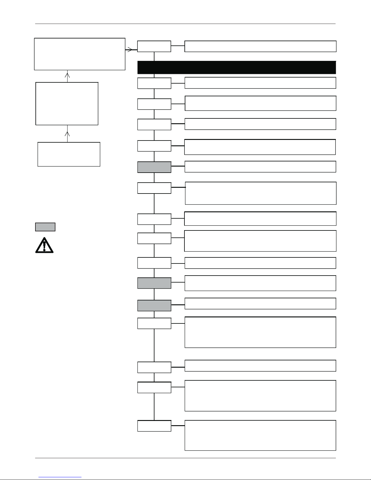
Einstellungen Dual QAM (Kanalschlüssel XX2/3X mit/ohne Transportstream handling)
Bedienung
Auswahl des Menüpunktes und Einstellen der Ziffern in entsprechender Menüzeile mit den UP/DOWNTasten . Eingabe der Werte
und Ein- Ausstieg in die Menüzeile
Speichern: Automatisch nach dem
Einstellen. Nach einem Netzausfall
bleiben alle Daten erhalten
.
Module mit TS-Handling
1) OP-ID und PIDFlt werden
bei Wechsel der Eingangsfrequenz auf OFF gesetzt!
2) nur in Dual QAM mit TS
handling und DVB-S und/oder
ASI, DVB-S2 Modulen!
Page 5
- 5 -
OV75M A/B=Kanal
1237 MHz= Eingangsfrequenz A/B
471.00=Ausgangsfrequenz
BER <1.0e-4=Bitfehlerrate
Channel
OV75M
V1.00
busy
Eingangskanal A/B
F-Out*
45-862 MHz,
1-MHz-Schritte
loop =
Durchschleifbetrieb
single
= Einzelausgang
1.000-7.499 kBaud
?Symbolrate?
Wert liegt ausserhalb des Einstellbereiches
????? siehe Warnhinweis
auto/on: auto:QAM-Signal schaltet ab, wenn Bedingung
im Warnhinweis erfüllt ist. on: Signal schaltet nicht ab
Out-Att*
0-10 dB
Augangspegel, 1-dB-Schritte
OutConf*
QAMRate*
QAMCarr*
QAMSpec*
normal / inverse
Modules*
Mod-No*
Anzeige Modulnummer
0-9
Version*
Overflow-Zähler zeigt die Häufigkeit des "Überlaufens"an.
Reset des Zählers mit
ModVers
Program
Die Liste zeigt die Programmnamen des empfangenen
Transponders an. Auswahl der Programme mit Pfeiltaste
.
Ein
*
bestätigt die Selektion.
Je Kanal muß mindestens
1 Programm selektiert sein.
Ist die Summendatenrate zu hoch, kommt die Meldung:
!Overfl
.nach Verlassen des Menüs. Programmanzahl
reduzieren.
MUXStat
Anzahl der selektierten Programme auf Kanal A/B
MUX on
- Statusanzeige
Hier - Einstellungen für Eingangsmodul einfügen
OV75M
V1.00
Mod No /
Mod init /
REMUX init
!Overflow
QAMMode*
16, 32, 64, 128, 256 QAM Modulationsart
Anzeige der eingesetzten Module
A:DVBS
- Modul
B:DVBS
- Modul
Remux
T=TV
R=Radio
= verschlüsselt
Version Grundmodul,
Softwareversion Modul
Softwareversion QAM-Modul
Overflow Zähler
Version
V 1.00
1607020
00...99
Anzeige Hard- Softwareversion Eingangsmodule
A: DVBS
- Modul
S1.0003
- Softwareversion
H1.0000
- Hardwareversion
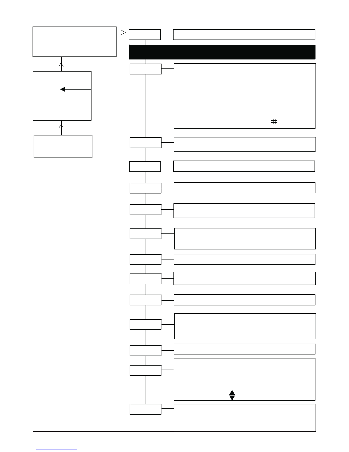
Bedienung
Auswahl des Menüpunktes und
Einstellen der Ziffern in entsprechender Menüzeile mit den
UP/DOWN-Tasten . Eingabe
der Werte und Ein- Ausstieg in die
Menüzeile
Speichern: Automatisch nach dem
Einstellen. Nach einem Netzausfall
bleiben alle Daten erhalten
.
Einstellungen Remux-QAM (Kanalschlüssel XX11)
nur bei
Kanal A*
Kanal B**
Hinweis:
Verschlüsselte Programme werden
nur im Kanal A durchgereicht.
Page 6
- 6 -
Einstellungen COFDM Remux-Mode (Kanalschlüssel XX41)
OV75M A/B=Kanal
476MHz= Eingangsfrequenz A/B
479.00=Ausgangsfrequenz A/B,
<1.0e-4=BER, Anzeige alternierend
Channel
OV75M
V1.00
busy
Kanal A/B
Mode*
Remux,
Betriebsart Remultiplexer
NonHier
, Betriebsart: NonHierarchischer
Hier
, Betriebsart: Hierarchischer
DVBTRep,
Repeater-Mode, wenn DVB-T-Modul gesteckt
OV75M A
V1.00
busy
Hier - Einstellungen für Eingangsmodul einfügen
F-Out*
45-862 MHz, 0.25-MHz-Schritte
loop =
Durchschleifbetrieb,
single
= Einzelausgang
auto/on
: auto:COFDMCarrier-Signal schaltet ab, wenn
Bedingung im Warnhinweis erfüllt ist. on: Schaltet nicht ab
Out-Att*
0-16 dB Augangspegel, 1-dB-Schritte
OutConf*
Out-BW*
COFDMCa*
COFDMSp*
normal / inverse COFDM-Spektrum
Program
Die Liste zeigt die Programmnamen des empfangenen
Transponders an. Auswahl der Programme mit Pfeiltaste .
Ein
*
bestätigt die Selektion.
Je Kanal muß mindestens
1 Programm selektiert sein.
Summendatenrate zu hoch:
!Overfl
.nach Verlassen des
Menüs erscheint. Programmanzahl reduzieren.
Anzeigen:
T=TV; R=Radio; = verschlüsselt
MUXStat
Anzahl der selektierten Programme auf Kanal A/B
MUX on - Statusanzeige
QAMMode*
16 QAM, 64 QAM, QPSK
Modulationsart
5, 6, 7, 8 MHz = Ausgangsbandbreite
Coderat
1/2, 2/3, 3/4, 5/6, 7/8
Coderate
k-Mode*
2k, 8k
k-Mode
Guardin*
1/4, 1/8, 1/16, 1/32 Guard-Intervall
NIT-Ins
On, off
Network Information Table Eingabe
NetName
Netzwerkname
7stellig
off oder HEX code 0 x 0000 Network identifier
F F F F
OrgTsId
NetwId
offoder HEX code
0 x 0000 Transport Stream identifier
F F F F
TsId
A
off oder HEX code
0 x 0000 Original Transport Stream
F F F F Identifier
nur bei
Kanal A*
Kanal B**
B
Hinweis: Einstellungen, die
mit A markiert sind.
Einige SetTopBoxen benötigen Zugriff auf die NITInformationen, um den
Transportstrom korrekt darzustellen. Ab COFDM-Version
11...
Werkseitig: auf on
Page 7
- 7 -
F-Out*
45-862 MHz,
0.25-MHz-Schritte
loop =
Durchschleifbetrieb,
single
= Einzelausgang
auto/on
: auto:COFDMCarrier-Signal schaltet ab, wenn
Bedingung im Warnhinweis erfüllt ist. on: Schaltet nicht ab
Out-Att*
0-16 dB
Augangspegel, 1-dB-Schritte
OutConf*
Out-BW*
COFDMCa*
COFDMSp*
normal / inverse
COFDM-Spektrum
Modules*
Mod-No*
Anzeige Modulnummer
0-9
Version*
Overflow-Zähler zeigt die Häufigkeit des "Überlaufens"an.
Reset des Zählers mit
ModVers
Program
Die Liste zeigt die Programmnamen des empfangenen
Transponders an. Auswahl der Programme mit Pfeiltaste .
Ein
*
bestätigt die Selektion.
Je Kanal muß mindestens
1 Programm selektiert sein.
Summendatenrate zu hoch:
!Overfl
.nach Verlassen des
Menüs erscheint. Programmanzahl reduzieren.
Anzeigen:
T=TV; R=Radio; = verschlüsselt
MUXStat
Anzahl der selektierten Programme auf Kanal A/B
MUX on
- Statusanzeige
QAMMode*
16 QAM, 64 QAM, QPSK
Modulationsart
A:DVBT
- Modul - Anzeige der eingesetzten Module
B:DVBS
- Modul
Version Grundmodul,
Softwareversion Modul
interne Daten
Overflow Zähler
Version
V 1.00
1109012
00...99
Anzeige Hard- Softwareversion Eingangsmodule
A: DVBS
- Modul
S1.0003
- Softwareversion
H1.0000
- Hardwareversion
5, 6, 7, 8 MHz =
Ausgangsbandbreite
Coderat
1/2, 2/3, 3/4, 5/6, 7/8
Coderate
k-Mode*
2k, 8k
k-Mode
Guardin*
1/4, 1/8, 1/16, 1/32
Guard-Intervall
NIT-Ins
On, off
Network Information Table Eingabe
NetName
Netzwerkname
7stellig
off oder HEX code
0 x 0000 Network identifier
F F F F
OrgTsId
NetwId
offoder HEX code
0 x 0000 Transport Stream identifier
F F F F
TsId
off oder HEX code
0 x 0000 Original Transport Stream
F F F F Identifier
B
Page 8
- 8 -
Einstellungen COFDM Hierarchical-Mode (Kanalschlüssel XX41)
OV75M A/B=Kanal
476 MHz= Eingangsfrequenz A/B
479.00=Ausgangsfrequenz A/B,
<1.0e-4=BER, Anzeige alternierend
Channel
OV75M
V1.00
busy
Kanal
A/B
Mode*
Remux, Betriebsart Remultiplexer
NonHier, Betriebsart Hierarchischer Betrieb AUS
Hier, Betriebsart Hierarchischer Betrieb EIN
OV75M A
V1.00
busy
Hier - Einstellungen für Eingangsmodul einfügen
F-Out*
45-862 MHz,
0.25-MHz-Schritte
loop =
Durchschleifbetrieb,
single
= Einzelausgang
Out-Att*
0-16 dB
Augangspegel, 1-dB-Schritte
OutConf*
Out-BW*
HPProgr
MUXStat
Anzahl der selektierten Programme auf Kanal A/B
MUX on
- Statusanzeige
QAMMode*
16 QAM, 64 QAM, QPSK
Modulationsart
5, 6, 7, 8 MHz =
Ausgangsbandbreite
LPProgr**
Die Liste zeigt die Programmnamen des empfangenen
Transponders an. Auswahl der Low Priority
Programme mit Pfeiltaste
.
LP CR**
1/2, 2/3, 3/4, 5/6, 7/8
Low Priority Coderatee
Die Liste zeigt die Programmnamen des empfangenen
Transponders an. Auswahl der High priority Programme
mit Pfeiltaste
. Ein
*
bestätigt die Selektion.
Je Kanal
muß mindestens 1 Programm selektiert sein.
Ist die Summendatenrate zu hoch, kommt die Meldung:
!Overfl
.nach Verlassen des Menüs. Programmanzahl
reduzieren. Anzeigen:
T=TV; R=Radio; = verschlüsselt
NIT-Ins
On, off
Network Information Table Eingabe
NetName
Netzwerkname
7stellig
off oder HEX code
0 x 0000 Network identifier
F F F F
OrgTsId
NetwId
offoder HEX code
0 x 0000 Transport Stream identifier
F F F F
TsId
A
off oder HEX code
0 x 0000 Original Transport Stream
F F F F Identifier
B
nur bei
Kanal A*
Kanal B**
Hinweis: Einstellungen, die
mit A markiert sind.
Einige SetTopBoxen benötigen Zugriff auf die NITInformationen, um den
Transportstrom korrekt darzustellen.
Ab COFDM-Version
11...
Werkseitig: auf on
Bei zwei Frontend-Modulen
kann einem Modul die Priorität zugewiesen werden.
Page 9
- 9 -
B
nur bei
Kanal A*
Kanal B**
auto/on
: auto:COFDMCarrier-Signal schaltet ab, wenn
Bedingung im Warnhinweis erfüllt ist. on: Schaltet nicht ab
COFDMCa*
COFDMSp*
normal / inverse
COFDMSpektrum
Modules*
Mod-No*
Anzeige Modulnummer
0-9
Version*
Overflow-Zähler zeigt die Häufigkeit des "Überlaufens"an.
Reset des Zählers mit
ModVers
A:DVBT
- Modul - Anzeige der eingesetzten Module
B:DVBS
- Modul
Version Grundmodul,
Softwareversion Modul
interne Daten
Overflow Zähler
Version
V 1.00
1109012
00...99
Anzeige Hard- Softwareversion Eingangsmodule
A/B: DVBS
- Modul
S1.0003
- Softwareversion
H1.0000
- Hardwareversion
HP CR*
1/2, 2/3, 3/4, 5/6, 7/8
High Priority Coderate
k-Mode*
2k, 8k
k-Mode
Guardin*
1/4, 1/8, 1/16, 1/32
Guard-Intervall
Alpha*
alpha 1, 2, 4
Spreizung Constellationsdiagramm
Page 10
- 10 -
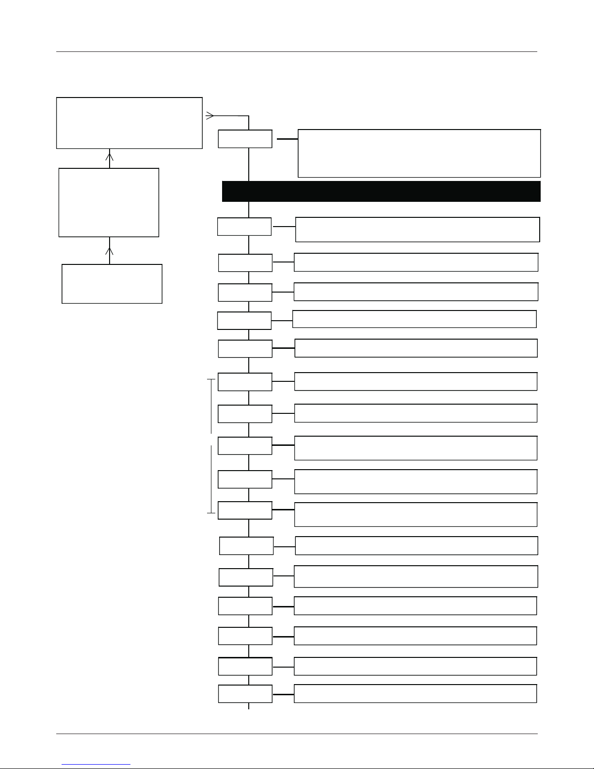
Einstellungen COFDM NonHierarchical-Mode (Kanalschlüssel XX41)
OV75M A=Kanal
476 MHz= Eingangsfrequenz A
479.00=Ausgangsfrequenz A,
<1.0e-4=BER, Anzeige alternierend
OV75M
V1.00
busy
Mode*
Remux,
Betriebsart Remultiplexer
NonHier
, Betriebsart: NonHierarchischer für ein
Frontend-Modul ch A
Hier
, Betriebsart: Hierarchischer
OV75M A
V1.00
busy
Hier - Einstellungen für Eingangsmodul einfügen
F-Out*
45-862 MHz,
0.25-MHz-Schritte
loop =
Durchschleifbetrieb,
single
= Einzelausgang
auto/on
: auto:COFDMCarrier-Signal schaltet ab, wenn
Bedingung im Warnhinweis erfüllt ist. on: Schaltet nicht ab
Out-Att*
0-16 dB
Augangspegel, 1-dB-Schritte
OutConf*
Out-BW*
COFDMCa*
COFDMSp*
normal / inverse
COFDMSpektrum
MUXStat
Anzahl der selektierten Programme auf Kanal A
MUX on
- Statusanzeige
QAMMode*
16 QAM, 64 QAM, QPSK
Modulationsart
5, 6, 7, 8 MHz =
Ausgangsbandbreite
k-Mode*
2k, 8k
k-Mode
Guardin*
1/4, 1/8, 1/16, 1/32
Guardintervall
Coderat
1/2, 2/3, 3/4, 5/6, 7/8
Coderate
NIT-Ins
On, off
Network Information Table Eingabe
NetName
Netzwerkname
7stellig
off oder HEX code
0 x 0000 Network identifier
F F F F
OrgTsId
NetwId
offoder HEX code
0 x 0000 Transport Stream identifier
F F F F
TsId
A
off oder HEX code
0 x 0000 Original Transport Stream
F F F F Identifier
nur bei
Kanal A*
Kanal B**
B
Hinweis: Einstellungen,
die mit A markiert sind.
Einige SetTopBoxen benötigen Zugriff auf die NITInformationen, um den
Transportstrom korrekt darzustellen. Ab COFDM-Version
11...
Werkseitig: auf on
Page 11
- 11 -
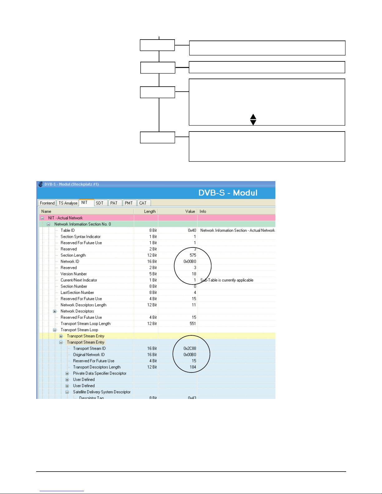
Mode*
Remux,
Betriebsart Remultiplexer
NonHier
, Betriebsart: NonHierarchischer für ein
Frontend-Modul ch A
Hier
, Betriebsart: Hierarchischer
Hier - Einstellungen für Eingangsmodul einfügen
F-Out*
45-862 MHz,
0.25-MHz-Schritte
loop =
Durchschleifbetrieb,
single
= Einzelausgang
auto/on
: auto:COFDMCarrier-Signal schaltet ab, wenn
Bedingung im Warnhinweis erfüllt ist. on: Schaltet nicht ab
Out-Att*
0-16 dB
Augangspegel, 1-dB-Schritte
OutConf*
Out-BW*
COFDMCa*
COFDMSp*
normal / inverse
COFDMSpektrum
Modules*
Mod-No*
Anzeige Modulnummer
0-9
Version*
Overflow-Zähler zeigt die Häufigkeit des "Überlaufens"an.
Reset des Zählers mit
ModVers
MUXStat
Anzahl der selektierten Programme auf Kanal A
MUX on
- Statusanzeige
QAMMode*
16 QAM, 64 QAM, QPSK
Modulationsart
A:DVBT
- Modul - Anzeige der eingesetzten Module
Version Grundmodul,
Softwareversion Modul
interne Daten
Overflow Zähler
Version
V 1.00
1109012
00...99
Anzeige Hard- Softwareversion Eingangsmodule
A: DVBT
- Modul
S1.0003
- Softwareversion
H1.0000
- Hardwareversion
5, 6, 7, 8 MHz =
Ausgangsbandbreite
k-Mode*
2k, 8k
k-Mode
Guardin*
1/4, 1/8, 1/16, 1/32
Guardintervall
Coderat
1/2, 2/3, 3/4, 5/6, 7/8
Coderate
NIT-Ins
On, off
Network Information Table Eingabe
NetName
Netzwerkname
7stellig
off oder HEX code
0 x 0000 Network identifier
F F F F
OrgTsId
NetwId
offoder HEX code
0 x 0000 Transport Stream identifier
F F F F
TsId
off oder HEX code
0 x 0000 Original Transport Stream
F F F F Identifier
B
Die NIT - Network Information Table enthält die Spezifikationen
der Transponder und der Programme, die in einem Datenstrom
übertragen werden, wie z. Bsp
- Sendefrequenz
- Symbolrate
- Informationen für Receiver und Settop-Boxen
NIT - Information
Abb. Auszug aus TS-Analyse
mit OTxxxx Transport Stream
Multiplexer
Page 12
- 12 -
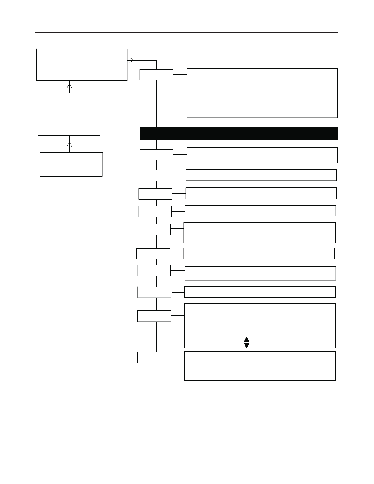
Einstellungen COFDM DVB-T-Repeater-Mode (Kanalschlüssel 4041)
OV75M A/B=Kanal
1237MHz= Eingangsfrequenz A/B
479.00=Ausgangsfrequenz A/B,
<1.0e-4=BER, Anzeige alternierend
OV75M
V1.00
busy
Mode
DVBTRep, Repeater-Mode, wenn DVB-T-Modul
gesteckt ist. Eingangsparameter werden an
COFDM weitergereicht!
Remux, Betriebsart Remultiplexer
NonHier, Betriebsart: NonHierarchischer
Hier, Betriebsart: Hierarchischer
OV75M A
V1.00
busy
Hier - Einstellungen für DVB-T-Eingangsmodul einfügen
F-Out
45-862 MHz,
0.25-MHz-Schritte
loop =
Durchschleifbetrieb,
single
= Einzelausgang
auto/on
: auto:COFDMCarrier-Signal schaltet ab, wenn
Bedingung im Warnhinweis erfüllt ist.
on: Signal schaltet nicht ab.
Out-Att
0-16 dB
Augangspegel, 1-dB-Schritte
OutConf
COFDMCa
COFDMSp
normal / inverse
COFDMSpektrum
Modules
Mod-No
Anzeige Modulnummer
0-9
Version
Overflow-Zähler zeigt die Häufigkeit des "Überlaufens"an.
Reset des Zählers mit
ModVers
MUXStat
Anzahl der selektierten Programme
MUX on
- Statusanzeige
A:DVBT - Modul - Anzeige der eingesetzten Module
Version Grundmodul,
Softwareversion Modul
interne Daten
Overflow Zähler
Version
V 1.00
1109012
00...99
Anzeige Hard- Softwareversion Eingangsmodule
A: DVBT
- Modul
S1.0003
- Softwareversion
H1.0000
- Hardwareversion
Page 13
- 13 -
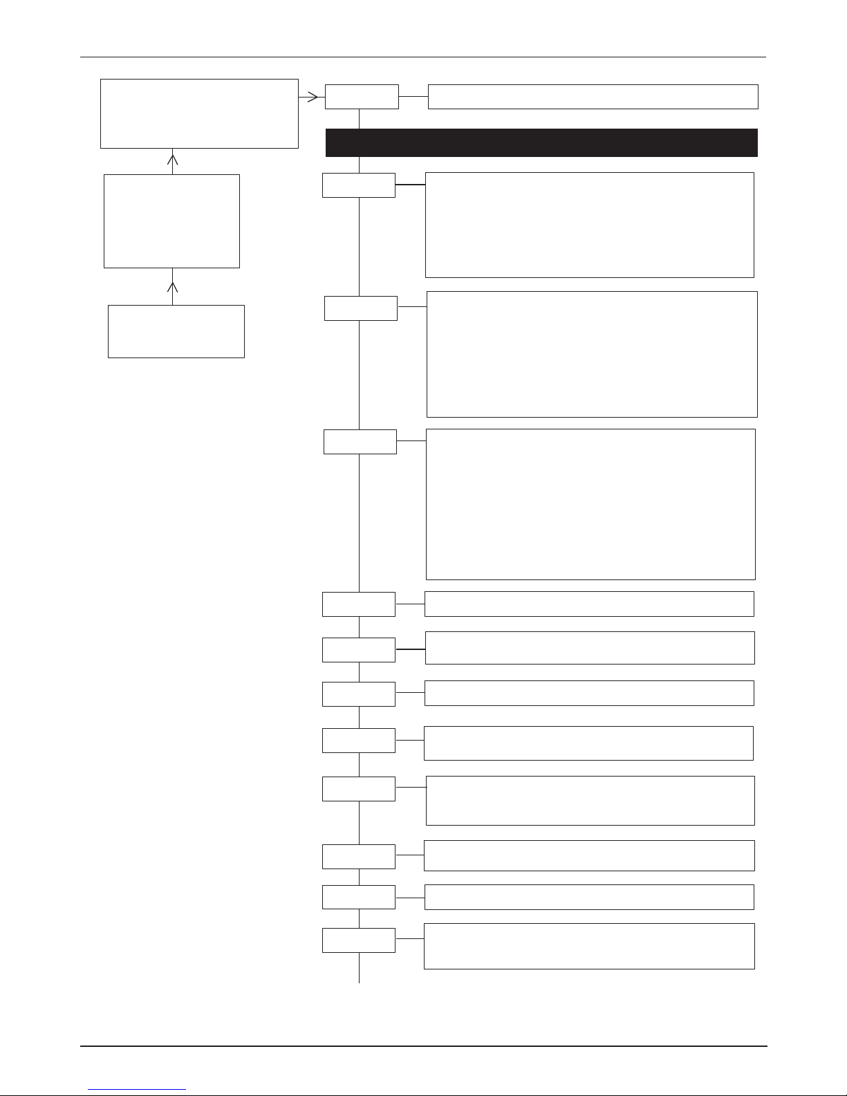
OV75M A/B=Kanal
1237MHz= Eingangsfrequenz A/B
479.00=Ausgangsfrequenz A/B,
<1.0e-4=BER, Anzeige alternierend
Channel
OV75M
V1.00
busy
Kanal
A/B
FE-all: Der komplette Transportstrom des Frontends
wird verwendet
FE-sel: Nur die im Menü “Prog” ausgewählten
Programme werden verwendet
ASI-all***: Der komplette Transportstrom des ASI-Modules
OV 67 wird verwendet
ASI-sel***: Nur die im Menü “Prog” ausgewählten
Programme werden verwendet
Source
OV75M
V1.00
Ch. A
Hier - Einstellungen für Eingangsmodul einfügen
F-Out*
Offset**
45-862 MHz,
1-MHz-Schritte
4-8 MHz - Ausgangskanalabstand,
Bsp.:Kanal A = 471,25 MHz + 8MHz Offset=Kanal B
loop =
Durchschleifbetrieb
single
= Einzelausgang
1.000-7.499 kBaud
?Symbolrate?
Wert liegt ausserhalb des Einstellbereiches
?????
siehe Warnhinweis
on/off
on: Signal eingeschaltet
off: Signal ausgeschaltet
OUT-Att*
0-15 dB Augangspegel, 1-dB-Schritte
OutConf*
QAMRate
Carrier**
QAMSpec
normal / inverse
16, 32, 64, 128, 256 QAM
Modulationsart
QAMMode
(2)
Prog****
Die Liste zeigt die Programmnamen des empfangenen
Transponders an. Auswahl der Programme mit Pfeiltaste
Ein
*
bestätigt die Selektion.
Je Kanal muß mindestens
1 Programm selektiert sein.
Ist die Summendatenrate zu hoch, kommt die Meldung:
!Overfl
.nach Verlassen des Menüs. Programmanzahl
reduzieren.
T=TV
R=Radio
#= verschlüsselt
CI
Die Liste zeigt die Programmnamen des empfangenen
Transponders an.
Auswahl der zu entschlüssenden Programme mit
Pfeiltaste
.
Ein
*
bestätigt die Selektion.
T=TV
R=Radio
#= verschlüsselt
Einstellungen Dual QAM mit CI (Kanalschlüssel X061 mit Transportstream handling)
Bedienung
Auswahl des Menüpunktes und
Einstellen der Ziffern in entsprechender Menüzeile mit den UP/
DOWN-Tasten . Eingabe der
Werte und Ein- Ausstieg in die
Menüzeile .
Ausstieg aus der 2. Ebene mit .
Speichern: Automatisch nach dem
Einstellen. Nach einem Netzausfall
bleiben alle Daten erhalten
.
* nur bei Kanal A
** nur bei Kanal B
*** nur bei einbegautem
ASI-Modul OV67
**** nur wenn im Menü
"Source" "FE-sel" oder
"ASI-sel" angewählt sind
B
Page 14
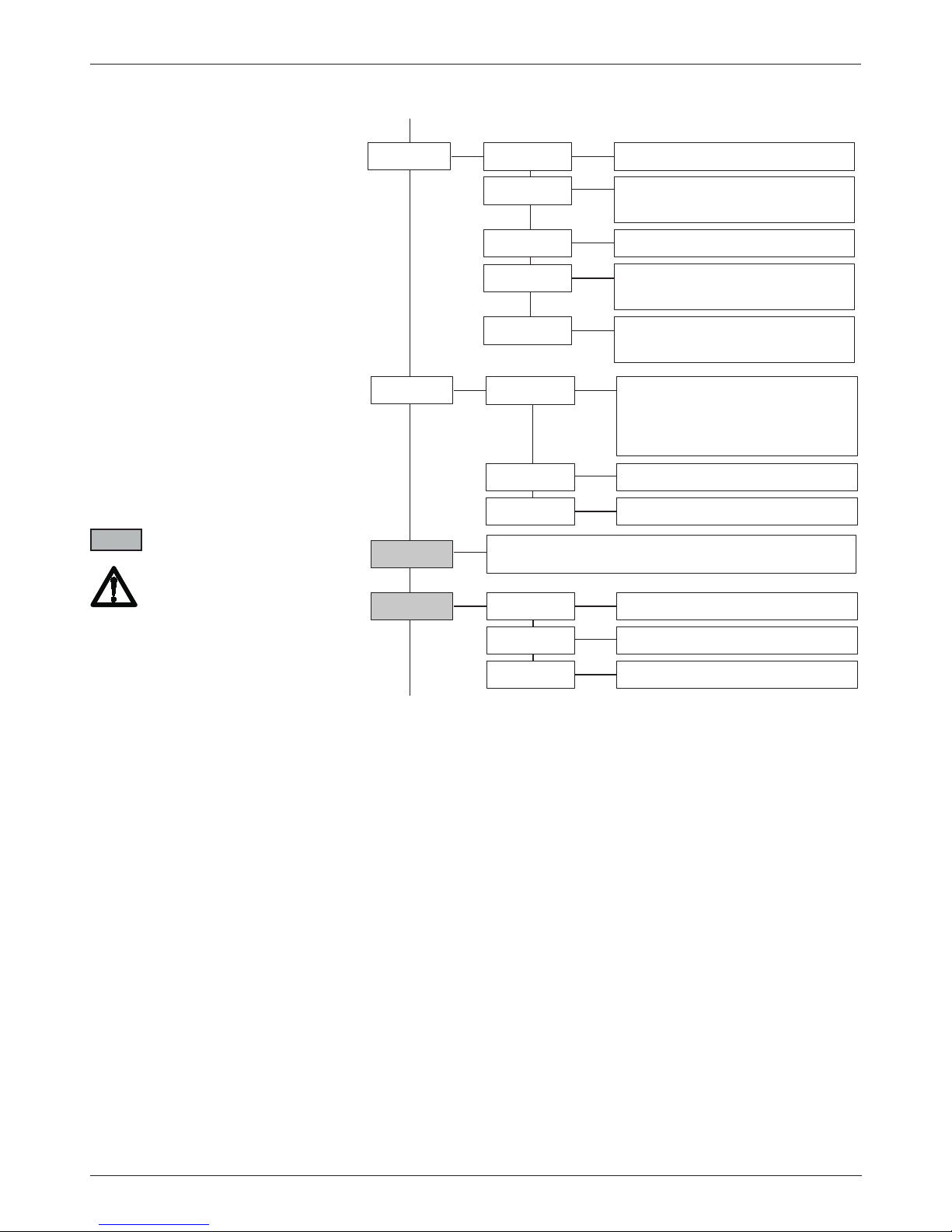
- 14 -
Einstellungen Dual QAM mit CI (Kanalschlüssel X061 mit Transportstream handling)
Op-ID
Operator ID,
0x0001-0xFFFF, Eingabe in Hex / off
(1)
PIDFltr
off oder Hex-Code 0x000 - 0x1FFF
(1)
PIDFlt0
off oder Hex-Code 0x000 - 0x1FFF
...
...
PIDFlt9
PIDAdd****
off oder Hex-Code 0x000 - 0x1FFF
Eingegebene PID wird von der
Filterung ausgeschlossen und
durchgelassen
PIDAdd0
off oder Hex-Code 0x000 - 0x1FFF
PIDAdd9
...
...
NIT-set
on/off Network Information Table
NIT-Gen
Netzwerkname 7stellig
NETName
off oder Hex-Code 0x000 - 0x1FFF
Transport Stream Identifier
TSID
off oder Hex-Code 0x000 - 0x1FFF
Original Transport Stream Identifier
O-NetID
off oder Hex-Code 0x000 - 0x1FFF
Network Identifier
NetID
Module mit TS-Handling
1) OP-ID und PIDFltr werden
bei Wechsel der Eingangsfrequenz auf OFF gesetzt!
2) nur in Dual QAM mit TS
handling und DVB-S und/oder
ASI, DVB-S2 Modulen!
B
C
**** nur wenn im Menü
"Source" "FE-sel" oder
"ASI-sel" angewählt sind
Page 15
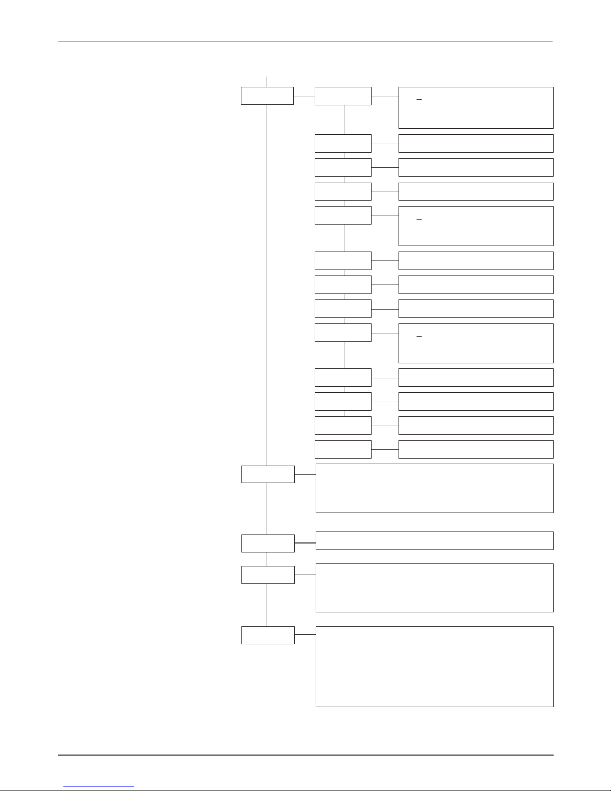
- 15 -
Einstellungen Dual QAM mit CI (Kanalschlüssel X061 mit Transportstream handling)
Modules
Anzeige der eingesetzten Module
A: DVBS2
- Modul
B: -------
- Modul
Dual-QAM
Mod-No
Anzeige Modulnummer
0-9
Version
Anzeige Version Grundgerät,
Software Modul
Software version QAM-Modul
interne Daten
ModVers
Anzeige Hard- Softwareversion Eingangsmodule
A: DVBS
- Modul
S1.0003
- Softwareversion
H1.0000
- Hardwareversion
M: MPEG2
- Modul
S1.0003
- Softwareversion
H1.0000
- Hardwareversion
Version
V 1.00
1607020
00
IP-sett
172 Cursor unter die einzustellende
Zahl schieben und mit ändern.
IP-Adresse einstellen
IPAddr0
29 IP-Adresse einstellen
IPAddr1
1 IP-Adresse einstellen
IPAddr2
91 IP-Adresse einstellen
IPAddr3
255 Cursor unter die einzustellende
Zahl schieben und mit ändern.
Netzwerkmaske einstellen
Mask0
255 Netzwerkmaske einstellen
Mask1
0 Netzwerkmaske einstellen
Mask2
0 Netzwerkmaske einstellen
Mask3
172 Cursor unter die einzustellende
Zahl schieben und mit ändern.
Gateway-Adresse einstellen
GWAddr0
29 Gateway-Adresse einstellen
GWAddr1
1 Gateway-Adresse einstellen
GWAddr2
92 Gateway-Adresse einstellen
GWAddr3
00039800000E Anzeige MAC-Adresse
MACAddr
C
Page 16
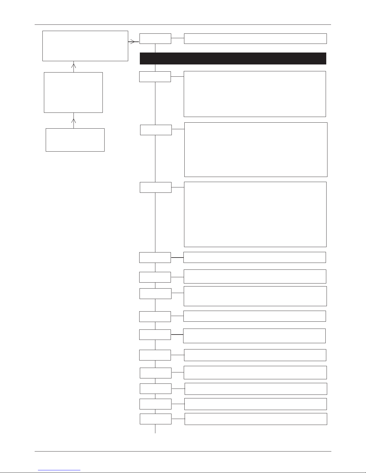
- 16 -
OV75M A/B=Kanal
1237MHz= Eingangsfrequenz A/B
479.00=Ausgangsfrequenz A/B,
<1.0e-4=BER, Anzeige alternierend
Channel
OV75M
V1.00
busy
Kanal
A/B
FE-all: Der komplette Transportstrom des Frontends
wird verwendet
FE-sel: Nur die im Menü “Prog” ausgewählten
Programme werden verwendet
ASI-all***: Der komplette Transportstrom des ASI-Modules
OV 67 wird verwendet
ASI-sel***: Nur die im Menü “Prog” ausgewählten
Programme werden verwendet
Source
OV75M
V1.00
Ch. A
Hier - Einstellungen für Eingangsmodul einfügen
F-Out*
Offset**
45-862 MHz,
1-MHz-Schritte
4-8 MHz - Ausgangskanalabstand,
Bsp.:Kanal A = 471,25 MHz + 8MHz Offset=Kanal B
5, 6, 7, 8 MHz = Ausgangsbandbreite
on/off
on: Signal eingeschaltet
off: Signal ausgeschaltet
OUT-Att*
0-15 dB Augangspegel, 1-dB-Schritte
Durchschleifbetrieb
loop
=
single
= Einzelausgang
OutConf*
Out-BW
Carrier**
1/2, 2/3, 3/4, 5/6, 7/8 CoderateHP CR
2k, 8k k-Modek-Mode
16 QAM, 64 QAM, QPSK
QAMMode
Modulationsart
.
Prog****
Die Liste zeigt die Programmnamen des empfangenen
Transponders an. Auswahl der Programme mit Pfeiltaste
Ein
*
bestätigt die Selektion.
Je Kanal muß mindestens
1 Programm selektiert sein.
Ist die Summendatenrate zu hoch, kommt die Meldung:
!Overfl
.nach Verlassen des Menüs. Programmanzahl
reduzieren.
T=TV
R=Radio
#= verschlüsselt
CI
Die Liste zeigt die Programmnamen des empfangenen
Transponders an.
Auswahl der zu entschlüssenden Programme mit
Pfeiltaste
.
Ein
*
bestätigt die Selektion.
T=TV
R=Radio
#= verschlüsselt
1/4, 1/8, 1/16, 1/32 GuardintervallGuardin
Einstellungen Dual COFDM mit CI NonHierarchical-Mode (Kanalschlüssel X071)
Bedienung
Auswahl des Menüpunktes und
Einstellen der Ziffern in entsprechender Menüzeile mit den UP/
DOWN-Tasten . Eingabe der
Werte und Ein- Ausstieg in die
Menüzeile .
Ausstieg aus der 2. Ebene mit .
Speichern: Automatisch nach dem
Einstellen. Nach einem Netzausfall
bleiben alle Daten erhalten
.
* nur bei Kanal A
** nur bei Kanal B
*** nur bei einbegautem
ASI-Modul OV67
**** nur wenn im Menü
"Source" "FE-sel" oder
"ASI-sel" angewählt sind
B
Page 17
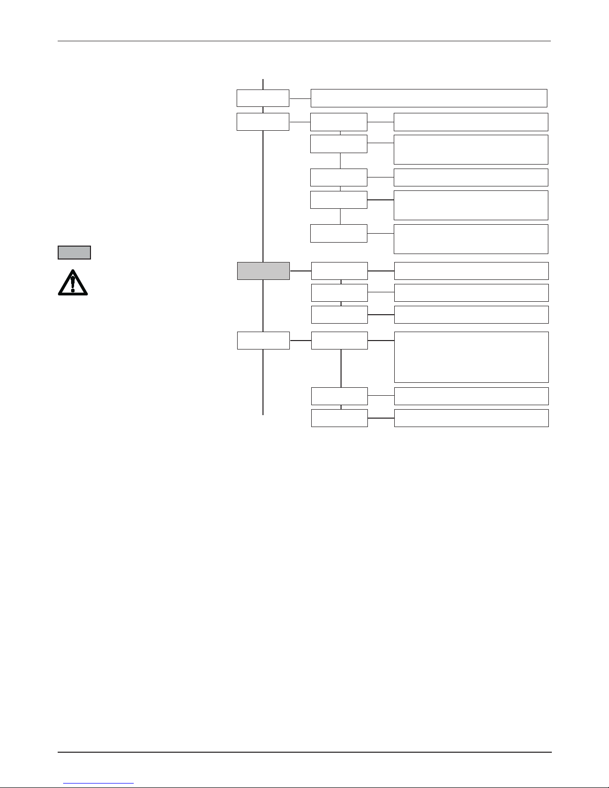
- 17 -
Einstellungen Dual COFDM mit CI NonHierarchical-Mode (Kanalschlüssel X071)
PIDAdd****
off oder Hex-Code 0x000 - 0x1FFF
Eingegebene PID wird von der
Filterung ausgeschlossen und
durchgelassen
PIDAdd0
off oder Hex-Code 0x000 - 0x1FFF
PIDAdd9
...
...
NIT-set
on/off Network Information Table
NIT-Gen
Netzwerkname 7stellig
NETName
off oder Hex-Code 0x000 - 0x1FFF
Transport Stream Identifier
TSID
off oder Hex-Code 0x000 - 0x1FFF
Original Transport Stream Identifier
O-NetID
off oder Hex-Code 0x000 - 0x1FFF
Network Identifier
NetID
PIDFltr
off oder Hex-Code 0x000 - 0x1FFF
(1)
PIDFlt0
off oder Hex-Code 0x000 - 0x1FFF
...
...
PIDFlt9
COFDMSp
normal / inverse COFDM-Spektrum
C
B
Module mit TS-Handling
1) OP-ID und PIDFltr werden
bei Wechsel der Eingangsfrequenz auf OFF gesetzt!
Page 18
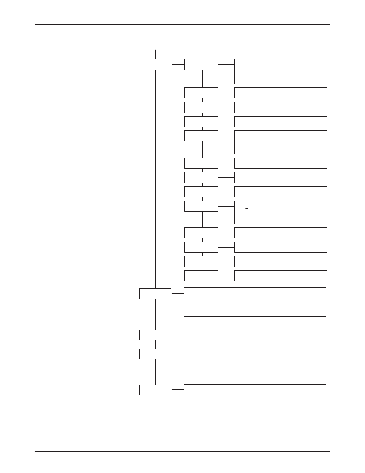
- 18 -
Einstellungen Dual COFDM mit CI NonHierarchical-Mode (Kanalschlüssel X071)
Modules
Anzeige der eingesetzten Module
A: DVBS
- Modul
B: DVBS
- Modul
Dual-QAM
Mod-No
Anzeige Modulnummer
0-9
Version
Anzeige Version Grundgerät,
Software Modul
Software version QAM-Modul
interne Daten
ModVers
Anzeige Hard- Softwareversion Eingangsmodule
A: DVBS
- Modul
S1.0003
- Softwareversion
H1.0000
- Hardwareversion
M: MPEG2
- Modul
S1.0003
- Softwareversion
H1.0000
- Hardwareversion
Version
V 1.00
1607020
00
IP-sett
172 Cursor unter die einzustellende
Zahl schieben und mit ändern.
IP-Adresse einstellen
IPAddr0
29 IP-Adresse einstellen
IPAddr1
1 IP-Adresse einstellen
IPAddr2
91 IP-Adresse einstellen
IPAddr3
255 Cursor unter die einzustellende
Zahl schieben und mit ändern.
Netzwerkmaske einstellen
Mask0
255 Netzwerkmaske einstellen
Mask1
0 Netzwerkmaske einstellen
Mask2
0 Netzwerkmaske einstellen
Mask3
172 Cursor unter die einzustellende
Zahl schieben und mit ändern.
Gateway-Adresse einstellen
GWAddr0
29 Gateway-Adresse einstellen
GWAddr1
1 Gateway-Adresse einstellen
GWAddr2
92 Gateway-Adresse einstellen
GWAddr3
00039800000E Anzeige MAC-Adresse
MACAddr
C
Page 19
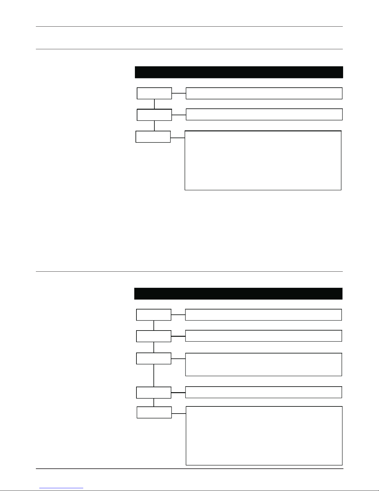
- 19 -
Sat-IF
950-2150 MHz
Auswahl der SAT-ZF, 1-MHz-Schritte
SymRate
BerRate
2.000-45.000 kSps
Symbolrate
<1.0 e-4
Die BER ist ein Mass für die Übertragungsfehler und
damit für die Signalqualität.
<1.0 e-4 = sehr geringe Fehler
1.0 e-3 = geringe Anzahl von Fehlern
1.0 e-2 = Schaltschwelle für Anzeige:
Signal?
Signal zu schlecht!
41,25 Mb = Eingangsdatenrate
DVBmode
S QPSK
- 1/2, 2/3, 3/4, 5/6, 7/8
S2 8QPSK
- 3/5, 2/3, 3/4, 5/6, 8/9, 9/10
S2 QPSK
- 1/2, 3/5, 2/3, 3/4, 4/5, 5/6, 8/9, 9/10
Pilot
on / off
Einstellungen für Eingangsmodul
Sat-IF
950-2150 MHz
Auswahl der SAT-ZF, 1-MHz-Schritte
SymRate
2.000-45.000 kSps
Symbolrate
Einstellungen für Eingangsmodul
BerRate
<1.0 e-4
Die BER ist ein Mass für die Übertragungsfehler und
damit für die Signalqualität.
<1.0 e-4 = sehr geringe Fehler
1.0 e-3 = geringe Anzahl von Fehlern
1.0 e-2 = Schaltschwelle für Anzeige:
Signal?
Signal zu schlecht!
41,25 Mb = Eingangsdatenrate
Einstellungen DVB-S (Kanalschlüssel 1XXX)
Einstellungen DVB-S2 (Kanalschlüssel 3XXX)
Eingangsmodule
Page 20
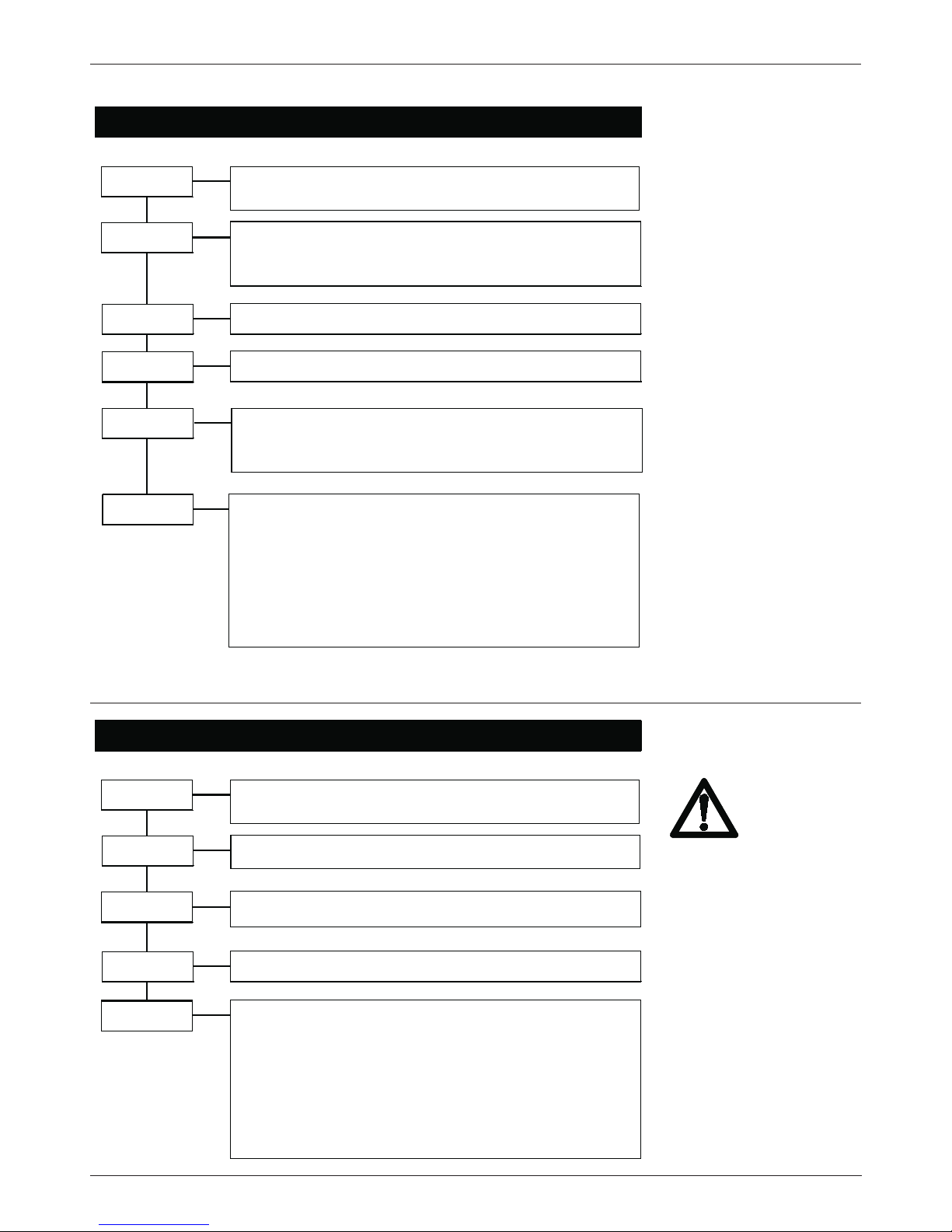
- 20 -
In-Freq
146-858 MHz
Auswahl der Eingangsfrequenz,
0.25-MHz-Schritte
In-Offs
BerRate
Eingangs-Offset
-166 kHz, 0, +166 kHz
bei 8 MHz
-125 kHz, 0, +125 kHz
bei 7 MHz
<1.0 e-4
Die BER ist ein Mass für die Übertragungsfehler und
damit für die Signalqualität.
<1.0 e-4 = sehr geringe Fehler
1.0 e-3 = geringe Anzahl von Fehlern
1.0 e-2 = Schaltschwelle für Anzeige:
Signal?
Signal zu schlecht!
14,46 Mb = Eingangsdatenrate
In-BW
Bandbreite 7 / 8 MHz
Einstellungen für Eingangsmodul
HierMod
Hierarchie-Auswahl (ab "ModVers":H2.000)
high (Priority)
low (Priority)
In-ATT
0 dB, 20 dB
Eingangsdämpfglied
(ab "ModVers":H2.000)
Einstellungen DVB-T (Kanalschlüssel 4XXX)
Einstellungen DVB-C (Kanalschlüssel 5XXX)
In-Freq
50-862 MHz
Auswahl der Eingangsfrequenz,
0.5-MHz-Schritte
In-Mode
BerRate
16, 32, 64, 128, 256 QAM
<1.0 e-4
Die BER ist ein Mass für die Übertragungsfehler und
damit für die Signalqualität.
<1.0 e-4 = sehr geringe Fehler
1.0 e-3 = geringe Anzahl von Fehlern
1.0 e-2 = Schaltschwelle für Anzeige:
Signal?
Signal zu schlecht!
38,15 Mb = Eingangsdatenrate
In-Att
0 dB, 20 dB
Eingangsdämpfglied
Einstellungen für Eingangsmodul
SymRate
1750-7125 kSps
Eingangssymbolrate
Bei zu hoher Kanallast,
selektives Kanalfilter in
den HF-Eingang schalten.
Page 21
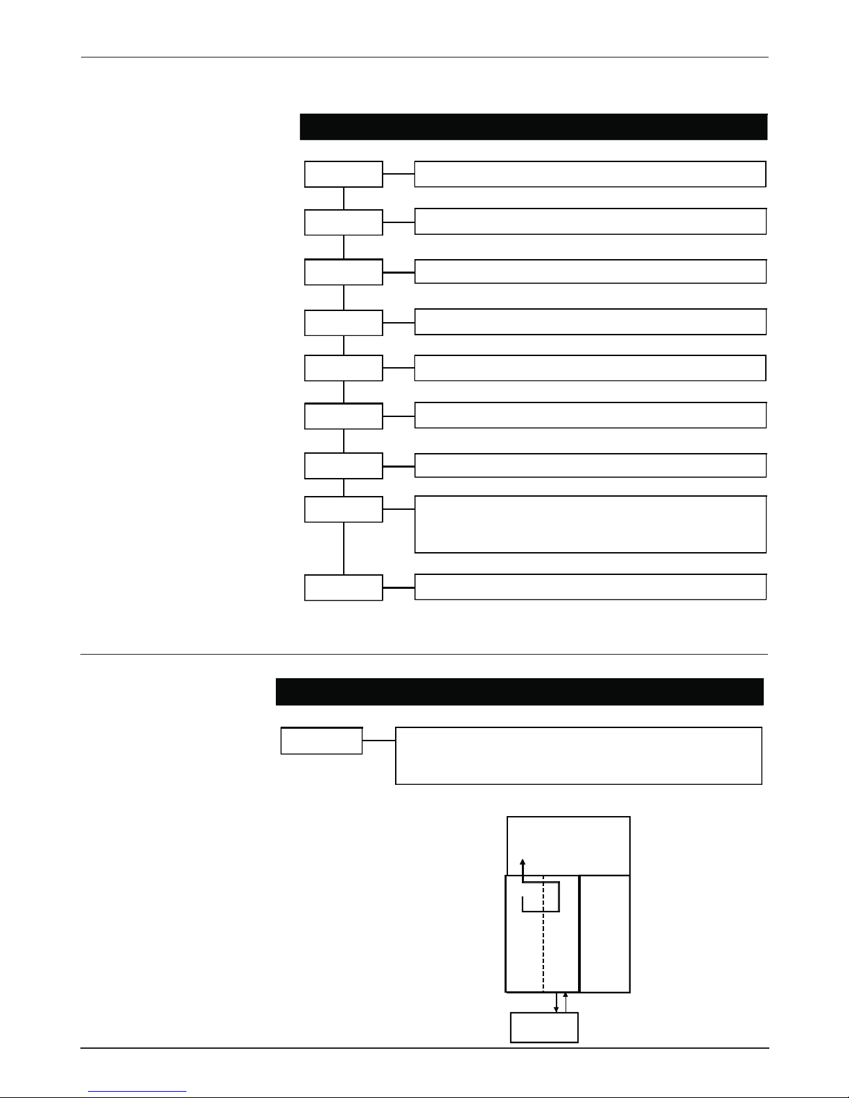
- 21 -
VidRate
3,0: 4,5; 6,0; 9,0
Mbit/s Ausgangs-Videodatenrate
A-Mode
Stereo, JointSt, Dual, Single
Name
Eingabe des Programm-Namens 7 stellig
Provid.
Einstellungen für Eingangsmodul
TP-Gen
on / off
blaues Testbild
Eingabe des Provider-Namens 7 stellig
TSID
Transport Stream Identifier; Eingabe in HEX
0 x FFFF
SID
Service Identifier; Eingabe in HEX 0 x FFFF
VidNorm
PAL, NTSC, SECAM
Videonorm auswählen!
Encode
Aud/Vid = Eintrag in die TV-Liste des Kabelreceivers
Audio = Eintrag in die Radio-Liste des Kabelreceivers
Encodiert nur das Audiosignal
Einstellungen AV-MPEG (Kanalschlüssel 6XXX)
Einstellungen ASI in/out (Kanalschlüssel 7XXX)
ASI loop
Einstellungen für Eingangsmodul
on /
schaltet das ASI-Modul zwischen Frontend und
QAM-Modulator (Kanal A). (B) wird abgeschaltet.
off
A
B
DVB-S
ASI
Descrambler
A=
on
QAM
B=
off
Hinweis: Sind mehrere AV-MPEG-oder
SDI Module eingebaut, dürfen keine gleichen HEX-Adressen verwendet werden.
Dies gilt auch für mehrere Module in
einer Kopfstelle!
Beispiel: ASI loop: on
Page 22
- 22 -
Einstellungen IP (100 Mb) (Kanalschlüssel 9XXX)
IPAddr 0
17
2
Cursor unter die einzustellende Zahl schieben und mit
ändern. IP-Adresse einstellen
29
IP-Adresse einstellen
1
IP-Adresse einstellen
Einstellungen für Eingangsmodul
Port
0-65535
Port-Adresse einstellen
91
IP-Adresse einstellen
IPAddr 1
IPAddr 2
IPAddr 3
MCAddr 0
MCAddr 1
MCAddr 2
MCAddr 3
ARPTime
Menü wird eingeblendet, wenn Multicast auf off steht.
ARPTime: off / 2-255s einstellbar.
MCast
23
9
Cursor unter die einzustellende Zahl schieben und mit
ändern. Multi-Cast-Adresse einstellen
255
Multi-Cast-Adresse einstellen
off/on
Multi-Cast on/off
255
Multi-Cast-Adresse einstellen
255
Multi-Cast-Adresse einstellen
MACAddr.
00039800000E
- Anzeige MAC-Adresse
0.9905 - Anzeige FPGA-Version
Page 23
- 23 -
Einstellungen SDI - MPEG (Kanalschlüssel AXXX)
VidRate
3,0: 4,5; 6,0; 9,0
Mbit/s Ausgangs-Videodatenrate
A-Mode
Stereo, JointSt, Dual, Single
Name
Eingabe des Programm-Namens 7 stellig
Provid.
Einstellungen für Eingangsmodul
TP-Gen
on / off
blaues Testbild
Eingabe des Provider-Namens 7 stellig
TSID
Transport Stream Identifier; Eingabe in HEX
0 x FFFF
SID
Service Identifier; Eingabe in HEX 0 x FFFF
Encode
Aud/Vid
= Eintrag in die TV-Liste des Kabelreceivers
Audio
= Eintrag in die Radio-Liste des Kabelreceivers
Encodiert nur das Audiosignal
Aud-Grp
analog, 7/8; 5/6; 3/4; 1/2 Auswahl der Audio-Gruppe
Aud-Vol
-18 ... +18 dB
6-dB-Schritte
Hinweis: Sind mehrere AV-MPEG-oder
SDI Module eingebaut, dürfen keine gleichen HEX-Adressen verwendet werden.
Dies gilt auch für mehrere Module in
einer Kopfstelle!
Page 24
- 24 -
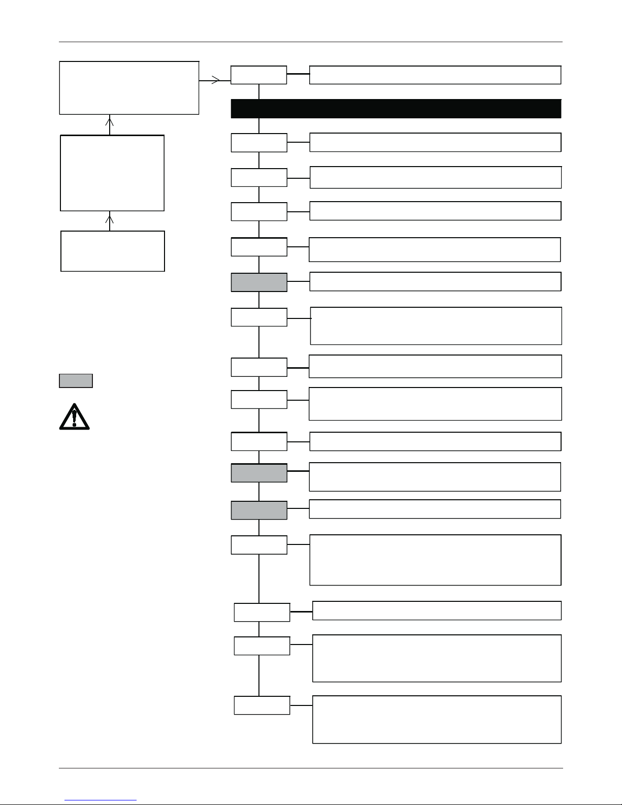
only at
Channel A*
Channel B**
OV75M A/B= channel
1237MHz=Input frequency A/B
479.00=output frequency A/B
<1.0e-4=BER, alternating
Channel
OV75M
V1.00
busy
Channel
A/B
F-Out*
Offset**
45-862 MHz,
1 MHz steps
4-8 MHz-Offset
Exp.: Ch A = 471,25 MHz + 8-MHz-Offset = Ch B
loop =
Loop through mode
single
= Single output
1.000-7.499 kBaud
?Symbol rate?
Incorrect symbole rate
????? refer to note
auto/on/off
: auto:QAM signal switches off autom.
on: signal doesn't switch off automatically.
off: signal switches to off
Out-Att*
0-10 dB
Output level, 1dB steps
OutConf*
Stuffin
on, off
- autom. insert of data bits
QAMRate
QAMCarr
QAMSpec
normal / inverse
PIDFlt 0-9
0-9,
10 filter, Hex code / off
Modules*
Displaying: modules
A: DVBS
- module
B: DVBS
- module
Dual-QAM
Mod-No*
Displaying: module number
0-9
Version*
version of basic unit,
software version module
software version QAM module
undocumented command
ModVers
Displaying: hard and software version of input modules
A: DVBS
- module
S1.0003
- software version
H1.0000
- hardware version
Insert here - input modules settings
16, 32, 64, 128, 256 QAM type of modulation.
QAMMode
OV75M
V1.00
Ch. A
(1)
(1)
Op-ID
Operator ID, 0x0001-0xFFFF, Hex. / off
(2)
(2)
Version
V 1.00
1607020
00
Settings Dual QAM (Key code XX2/3X with/without transport stream handling)
Operation
Select the menu item and
adjust the values in a menu line
with the UP/DOWN keys .
Enter values and enter and exit
from menu lines with the LEFT/
RIGHT keys.
Saving: Data are saved
automatically. Data are retained
in the case of a power failure.
GB
Modules with TS handling
1) Setting the input frequency:
the "OP-ID" and "PIDFlt turns
to OFF
2) Only for Dual QAM with TS
handling and DVB-S and/or
ASI, DVB-S2 modules
Page 25
- 25 -
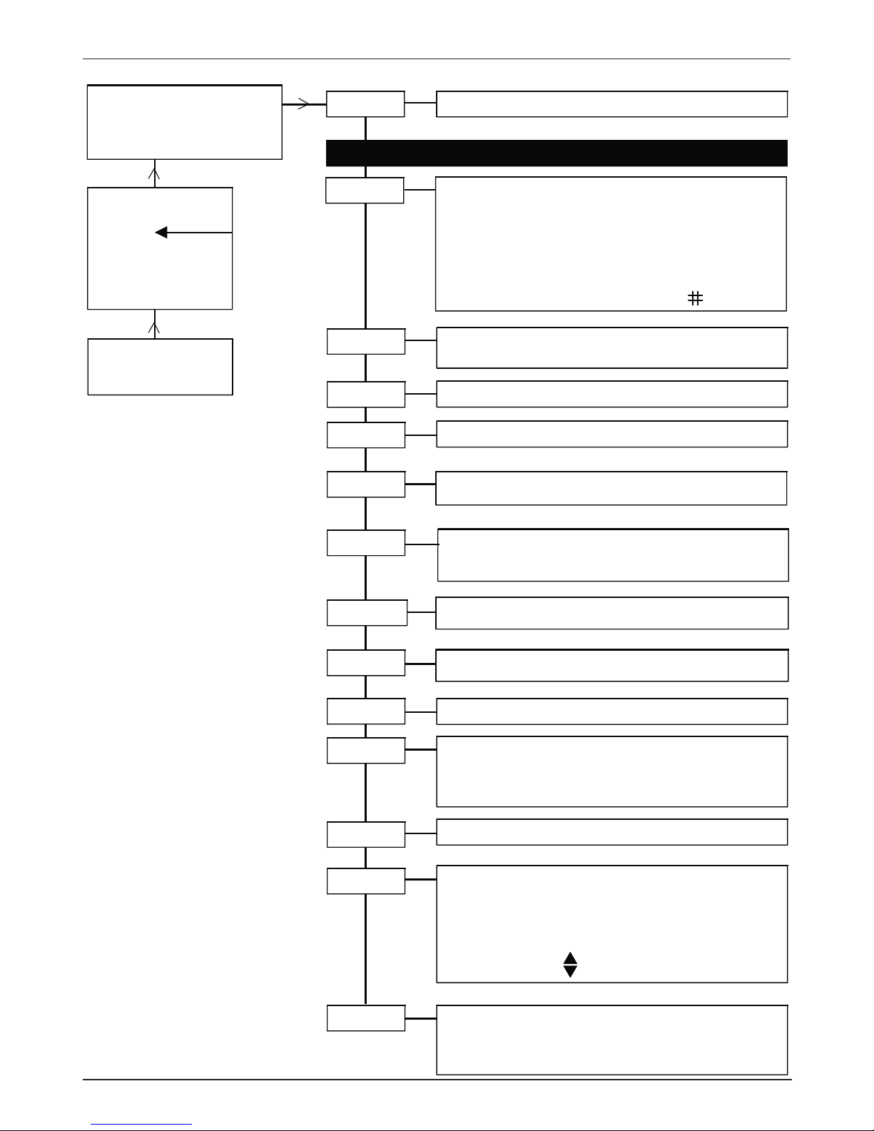
OV75M A/B= channel
1237MHz=Input frequency A/B
471.00=output frequency,
BER <1.0 e-4= Bit error rate
Channel
OV75M
V1.00
busy
Input channel A/B
Program
Displays the list of transponder name. Select program
with
A * confirms the selected programmes.
Important: Select one programme per channel
If
!Overfl
is displayed, (total data rate to high)
reduce the program numbers.
loop =
Loop through mode
Single
= Single output
1.000-7.499 kBaud
?Symbol rate?
Incorrect symbole rate
?????
refer to note
auto/on
: auto:QAM signal switches off atom. (see note),
on: signal doesn't switch off automatically.
Out-Att*
0-10 dB
Output level, 1dB steps
OutConf*
QAMRate*
QAMCarr*
QAMSpec*
normal / inverse
Modules*
Displaying: modules
A:DVBS
- module
B:DVBS
- module
Remux
Mod-No*
Displaying: module number
0-9
Version*
ModVers
Displaying: hard and software version of input modules
A:DVBS
- module
S1.0003
- software version
H1.0000
- hardware version
F-Out*
45-862 MHz,
1 MHz steps
MUXStat
Sum of selected programmes channel A/B
Mux on
- displaying status of Remux
Insert here - input module settings
OV75M
V1.00
Mod No/
Mod init/
REMUX init
!Overflow
16, 32, 64, 128, 256 QAM
type of modulation
QAMMode*
Overflow counter shows the account of "overflows".
Counter reset: press simultaneously
version of basic unit,
software version module
software version QAM module
Overflow counter
Version
V 1.00
1607020
00...99
T=tv
R=radio
= encrypted
Operation
Select the menu item and
adjust the values in a menu line
with the UP/DOWN keys .
Enter values and enter and exit
from menu lines with the LEFT/
RIGHT keys.
Saving: Data are saved
automatically. Data are retained
in the case of a power failure.
GB
Settings Remux-QAM (Key code XX11)
only at
Channel A*
Channel B**
Note:
Encryted programmes are passed
through only via channel A!
Page 26
- 26 -
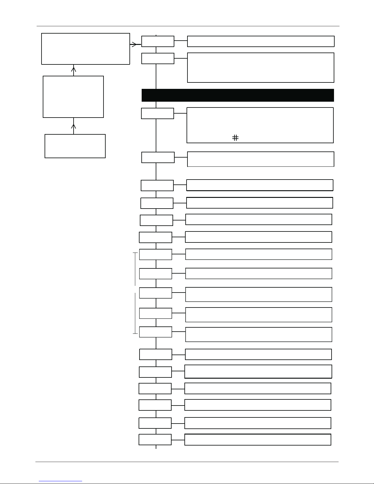
Settings COFDM Remux mode (Key code XX41)
only at
Channel A*
Channel B**
OV75M A/B=channel
1237MHz= input frequency A/B
479.00=output frequency A/B,
<1.0e-4=BER, alternating display
Channel
OV75M
V1.00
busy
Input channel
A/B
Mode*
Remux,
Remultiplexer mode
NonHier
, NonHierarchical mode
Hier
, Hierarchical mode
DVBTRep,
Repeater mode (available with DVB-T modul)
OV75M A
V1.00
busy
Please set all parameters of the frontend module settings
F-Out*
45-862 MHz,
0.25-MHz steps
loop =
Loop thru mode ,
single
= single output
auto/on
: auto:COFDMCarrier signal switches off.
On: signal doesn't switch off.
Out-Att*
0-16 dB
output level, 1-dB steps
OutConf*
Out-BW*
COFDMCa*
COFDMSp*
normal / inverse
COFDMSpectrum
Program
Displays the list of transponder name. Select program with
. A * confirms the selection . Select programme per
channel.
Indication of
!Overfl
.shows: (total data rate to high)
T=TV; R=R
adio; = encrypted
MUXStat
Sum of selected programmes ch A/B
MUX on
- displaying status of Remux
QAMMode*
16 QAM, 64 QAM, QPSK
type of modulation
5, 6, 7, 8 MHz =
output bandwidth
Coderat
1/2, 2/3, 3/4, 5/6, 7/8
Code rate
k-Mode*
2k, 8k
k mode
Guardin*
1/4, 1/8, 1/16, 1/32
Guard intervall
NIT-Ins
On, off
Network Information Table insertion
NetName
network name
7 digits
off or set HEX code
0 x 0000 Network identifier
F F F F
OrgTsId
NetwId
off or set HEX code
0 x 0000 Transport Stream Identifier
F F F F
TsId
off or set HEX code
0 x 0000 Original Transport Stream
F F F F Identifier
A
Output settings
GB
B
Note: Settings marked with A
Some SetTopBoxes on the market requires additional informations about NIT to scan correct
Transport Stream.
Available from
COFDM version 11
..
Factory setting: on
Page 27
- 27 -
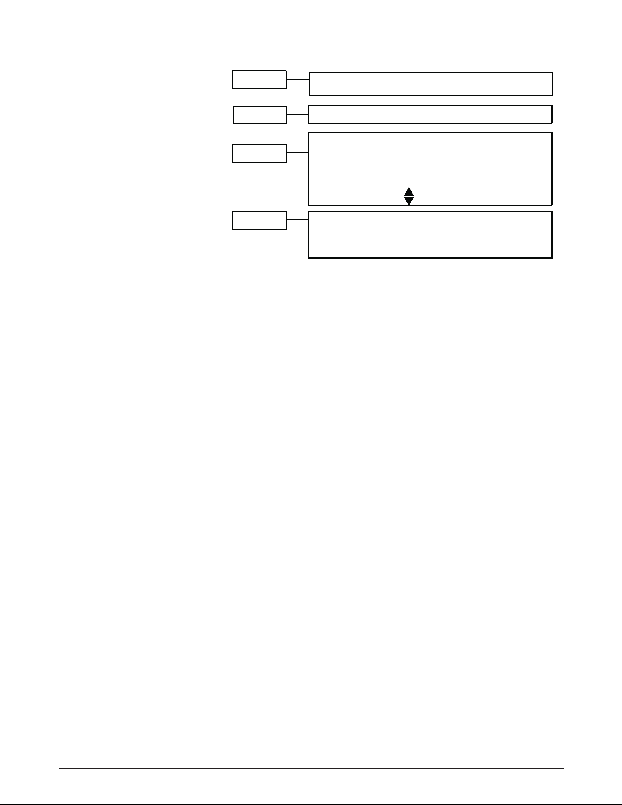
Please set all parameters of the frontend module settings
F-Out*
45-862 MHz,
0.25-MHz steps
loop =
Loop thru mode ,
single
= single output
auto/on
: auto:COFDMCarrier signal switches off.
On: signal doesn't switch off.
Out-Att*
0-16 dB
output level, 1-dB steps
OutConf*
Out-BW*
COFDMCa*
COFDMSp*
normal / inverse
COFDMSpectrum
Modules*
Mod-No*
Displaying module number
0-9
Version*
Overflow counter shows the account of "overflows".
Counter reset: press simultaneously
ModVers
Program
Displays the list of transponder name. Select program with
. A * confirms the selection . Select programme per
channel.
Indication of
!Overfl
.shows: (total data rate to high)
T=TV; R=R
adio; = encrypted
MUXStat
Sum of selected programmes ch A/B
MUX on
- displaying status of Remux
QAMMode*
16 QAM, 64 QAM, QPSK
type of modulation
A:AV-MPEG
- module - displaying modules
B:AV-MPEG
- module - displaying modules
basic unit version,
software version module
undocumented command
Overflow counter
Version
V 1.00
1109012
00...99
Displaying: hard and software version of input modules
A: AV-MPEG
- module
S1.0003
- software version
H1.0000
- hardware version
5, 6, 7, 8 MHz =
output bandwidth
Coderat
1/2, 2/3, 3/4, 5/6, 7/8
Code rate
k-Mode*
2k, 8k
k mode
Guardin*
1/4, 1/8, 1/16, 1/32
Guard intervall
NIT-Ins
On, off
Network Information Table insertion
NetName
network name
7 digits
off or set HEX code
0 x 0000 Network identifier
F F F F
OrgTsId
NetwId
off or set HEX code
0 x 0000 Transport Stream Identifier
F F F F
TsId
off or set HEX code
0 x 0000 Original Transport Stream
F F F F Identifier
A
Output settings
B
Page 28
- 28 -
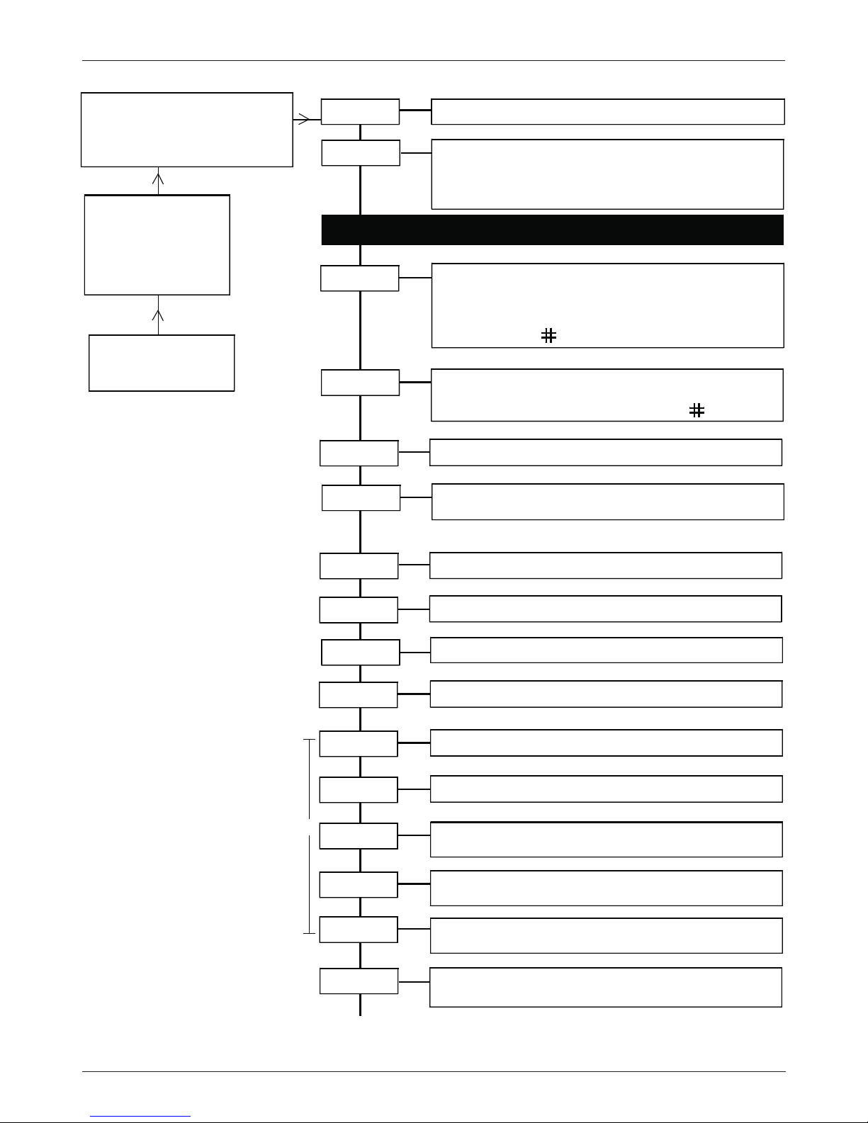
Settings COFDM Hierarchical mode (Key code XX41)
only at
Channel A*
Channel B**
OV75M A/B=channel
476 MHz= input frequency A/B
479.00=output frequency A/B,
<1.0e-4=BER, alternating display
Channel
OV75M
V1.00
busy
Input channel
A/B
Mode*
Remux,
Remultiplexer mode
NonHier
, NonHierarchical mode
Hier
, Hierarchical mode. chA/B one of the modules gets
the priority
OV75M A
V1.00
busy
Please set all parameters of the frontend modules
F-Out*
45-862 MHz,
0.25-MHz steps
loop =
Loop thru mode,
single
= single output
Out-Att*
0-16 dB
output level, 1-dB steps
OutConf*
Out-BW*
HP Progr*
MUXStat
Sum of selected programmes ch A/B
MUX on
- displaying status
QAMMode*
5, 6, 7, 8 MHz =
output bandwidth
LP Progr**
Displays the list of transponder name. Select low priority
program with
. A
*
confirms the selection. Select
programme per channel.
T=TV; R=R
adio; = encrypted
LP CR**
1/2, 2/3, 3/4, 5/6, 7/8,
Low Priority Code Rate
Displays the list of transponder name. Select high priority
program with
. A * confirms the selection. Select
programme per channel. Indication of
!Overfl
.shows:
(total data rate to high)
T=TV; R=R
adio; = encrypted
16 QAM, 64 QAM, QPSK
type of modulation
Output settings
NIT-Ins
On, off
Network Information Table insertion
NetName
network name
7 digits
off or set HEX code
0 x 0000 Network identifier
F F F F
OrgTsId
NetwId
off or set HEX code
0 x 0000 Transport Stream identifier
F F F F
TsId
A
off or set HEX code
0 x 0000 Original Transport Stream
F F F F Identifier
B
GB
Note: Settings marked with A
Some SetTopBoxes on the market requires additional informations about NIT to scan correct
Transport Stream.
Available from
COFDM version 11
..
Factory setting: on
Hierarchical mode supports two
frontend modules ch A/B. Set
priority to one of them.
Page 29
- 29 -
GB
B
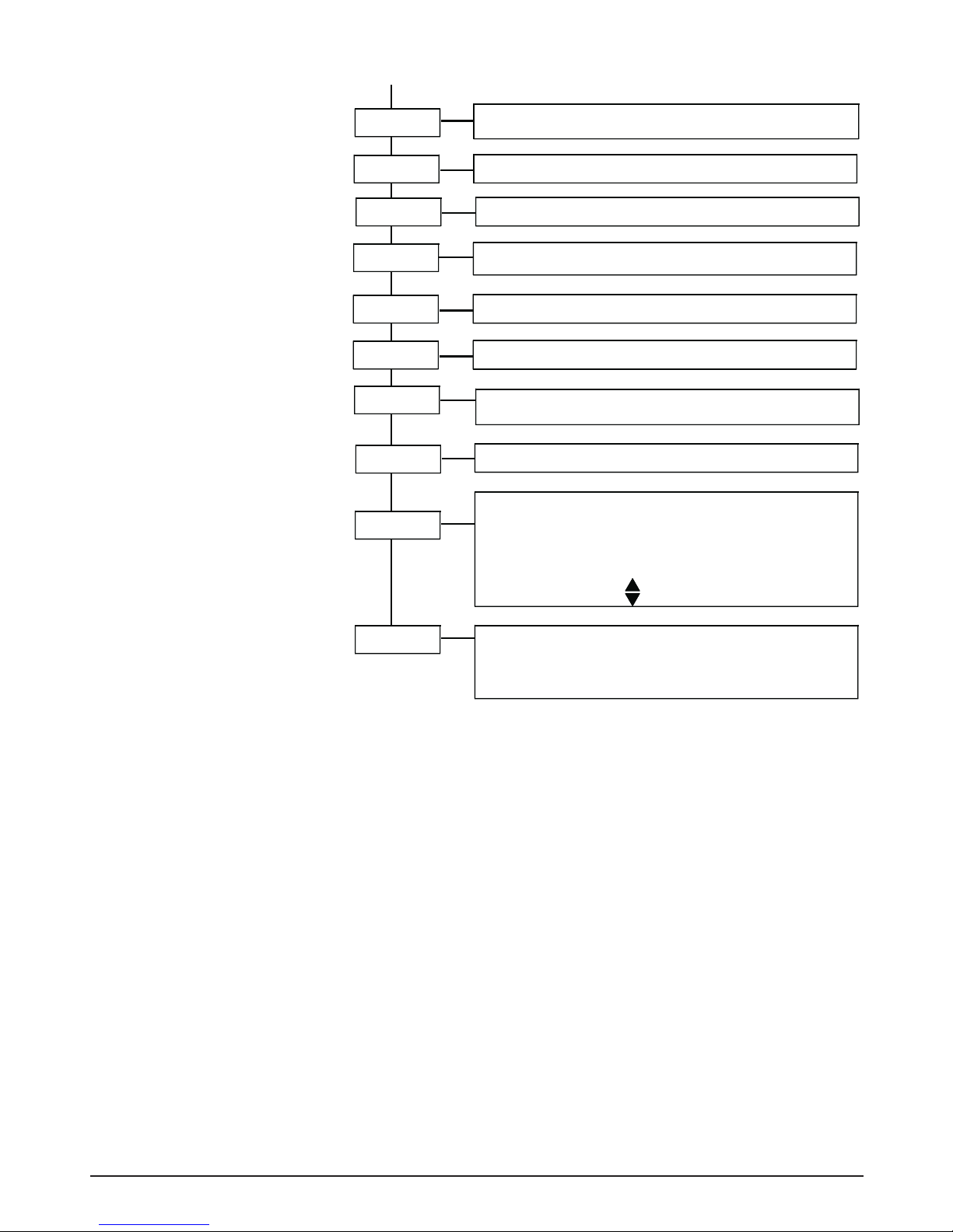
auto/on
: auto:COFDMCarrier signal switches off autom.
on: signal doesn't switch off automatically.
COFDMCa*
COFDMSp*
normal / inverse
COFDMSpectrum
Modules*
Mod-No*
Displaying module number
0-9
Version*
Overflow counter shows the account of "overflows".
Counter reset: press simultaneously
ModVers
A:AV-MPEG
- module - displaying modules
B:AV-MPEG
- module - displaying modules
basic unit version,
software version module
undocumented command
Overflow counter
Version
V 1.00
1109012
00...99
Displaying: hard and software version of input modules
A: AV-MPEG
- module
S1.0003
- software version
H1.0000
- hardware version
k-Mode*
2k, 8k
k mode
Guardin*
1/4, 1/8, 1/16, 1/32
Guard intervall
HP CR*
1/2, 2/3, 3/4, 5/6, 7/8
High Priority Coderate
Alpha*
alpha 1, 2, 4
Spreding of constellation diagram
Page 30
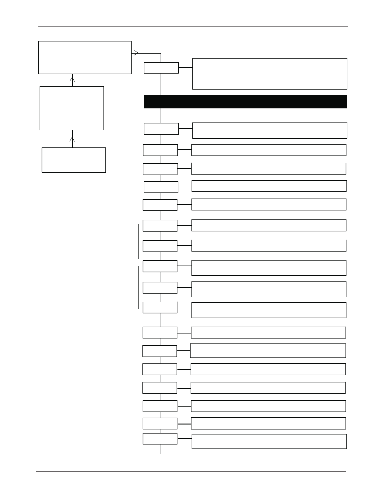
- 30 -
GB
Settings COFDM NonHierarchical mode (Key code XX41)
only at
Channel A*
Channel B**
OV75M A=channel
476 MHz= input frequency A
479.00=output frequency A,
<1.0e-4=BER, alternating display
OV75M
V1.00
busy
Mode*
Remux,
Remultiplexer mode
NonHier
, NonHierarchical mode (channel A -
one frontend module)
Hier
, Hierarchical mode
OV75M A
V1.00
busy
F-Out*
45-862 MHz,
0.25-MHz steps
loop =
Loop thru mode,
single
= single mode
Out-Att*
0-16 dB
output level, 1-dB steps
OutConf*
Out-BW*
MUXStat
Sum of selected programmes ch A
MUX on
- displaying status of Remux
5, 6, 7, 8 MHz =
output bandwidth
Please set all parameters of the DVB-T frontend module
Output settings
auto/on
: auto:COFDMCarrier signal switches off.
On: signal doesn't switch off.
COFDMCa*
COFDMSp*
normal / inverse
COFDMSpectrum
Modules*
QAMMode*
16 QAM 64 QAM, QPSK
type of modulation
DVBT-MPEG
- module - displaying modules
k-Mode*
2k, 8k
k mode
Guardin*
1/4, 1/8, 1/16, 1/32
Guard intervall
Coderat
1/2, 2/3, 3/4, 5/6, 7/8
Coderate
NIT-Ins
On, off
Network Information Table insertion
NetName
network name
7 digits
off or set HEX code
0 x 0000 Network identifier
F F F F
OrgTsId
NetwId
off or set HEX code
0 x 0000 Transport Stream identifier
F F F F
TsId
A
off or set HEX code
0 x 0000 Original Transport Stream
F F F F Identifier
B
NonHierarchical mode supports
one frontend module ch A
Note: Settings marked with A
Some SetTopBoxes on the market requires additional informations about NIT to scan correct
Transport Stream.
Available from
COFDM version 11
..
Factory setting: on
Page 31
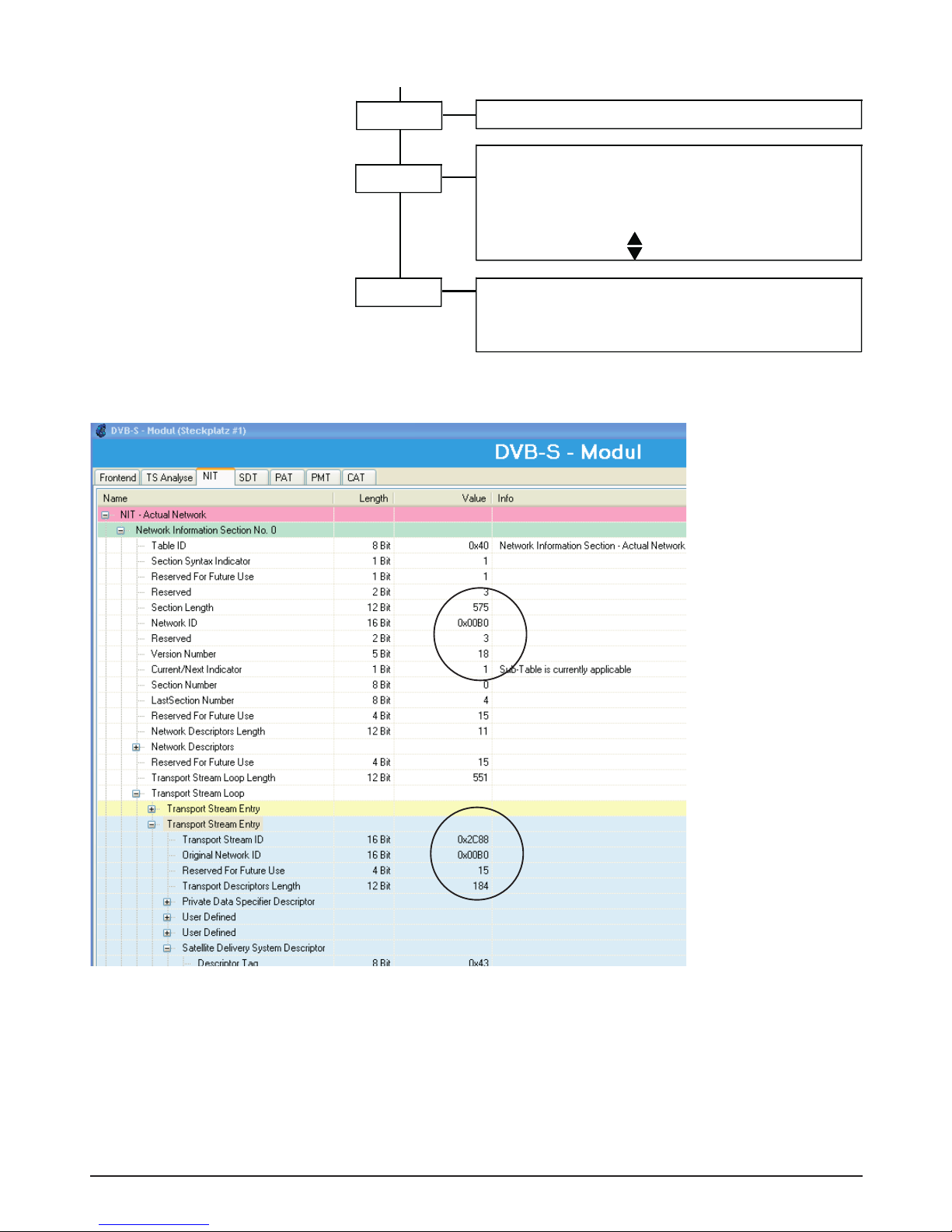
- 31 -
Mode*
Remux,
Remultiplexer mode
NonHier
, NonHierarchical mode (channel A -
one frontend module)
Hier
, Hierarchical mode
F-Out*
45-862 MHz,
0.25-MHz steps
loop =
Loop thru mode,
single
= single mode
Out-Att*
0-16 dB
output level, 1-dB steps
OutConf*
Out-BW*
MUXStat
Sum of selected programmes ch A
MUX on
- displaying status of Remux
5, 6, 7, 8 MHz =
output bandwidth
Please set all parameters of the DVB-T frontend module
Output settings
auto/on
: auto:COFDMCarrier signal switches off.
On: signal doesn't switch off.
COFDMCa*
COFDMSp*
normal / inverse
COFDMSpectrum
Modules*
Mod-No*
Displaying module number
0-9
Version*
Overflow counter shows the account of "overflows".
Counter reset: press simultaneously
ModVers
QAMMode*
16 QAM 64 QAM, QPSK
type of modulation
DVBT-MPEG
- module - displaying modules
basic unit version,
software version module
undocumented command
Overflow counter
Version
V 1.00
1109012
00...99
Displaying: hard and software version of input modules
A: DVBT
- module
S1.0003
- software version
H1.0000
- hardware version
k-Mode*
2k, 8k
k mode
Guardin*
1/4, 1/8, 1/16, 1/32
Guard intervall
Coderat
1/2, 2/3, 3/4, 5/6, 7/8
Coderate
NIT-Ins
On, off
Network Information Table insertion
NetName
network name
7 digits
off or set HEX code
0 x 0000 Network identifier
F F F F
OrgTsId
NetwId
off or set HEX code
0 x 0000 Transport Stream identifier
F F F F
TsId
off or set HEX code
0 x 0000 Original Transport Stream
F F F F Identifier
B
NIT - Information
Fig. extract of TS Analyzer
OTxxxx Transport Stream Multiplexer
The NIT – Network Information Table – contains the specifications
of the transponders and the programs transmitted in the data
stream, e.g.
- Transmission frequency
- Symbol rate
- Information for receivers and set-top boxes
Page 32
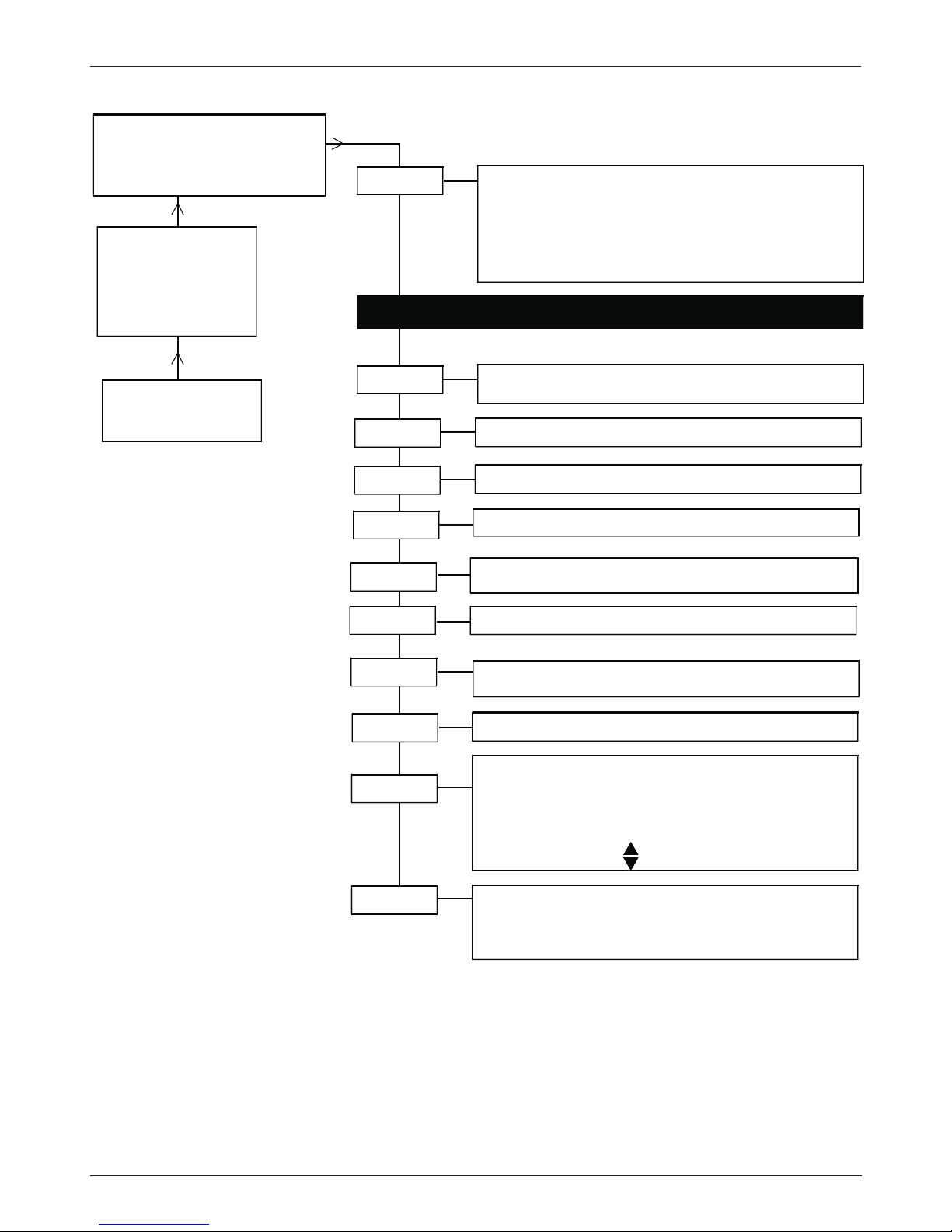
- 32 -
Setting COFDM DVB-T-Repeater mode (Key code 4041)
OV75M A/B=channel
476 MHz= input frequency A/B
479.00=output frequency A/B,
<1.0e-4=BER, alternating display
OV75M
V1.00
busy
Mode*
DVBTRep,
Repeater mode (available with DVB-T
module). Input parameters are passed on to
COFDM
Remux, Remultiplexer mode
NonHier, NonHierarchical mode
Hier, Hierarchical mode
OV75M A
V1.00
busy
Please set all parameters of the DVB-T frontend module
F-Out
45-862 MHz,
0.25-MHz steps
loop =
Loop thru mode,
single
= single output
auto/on
: auto:COFDMCarrier signal switches off.
On: signal doesn't switch off.
Out-Att
0-16 dB output level, 1-dB steps
OutConf
COFDMCa
COFDMSp
normal / inverse
COFDMSpectrum
Modules
Mod-No
Displaying module number
0-9
Version
Overflow counter shows the account of "overflows".
Counter reset: press simultaneously
ModVers
MUXStat
Sum of selected programmes
MUX on - displaying status of Remux
A:DVBT
- module - displaying modules
basic unit version,
software version module
undocumented command
Overflow counter
Version
V 1.00
1109012
00...99
Displaying: hard and software version of input modules
A: DVBT
- module
S1.0003
- software version
H1.0000
- hardware version
Output settings
GB
You require this mode when
only one DVB-T front-end module is plugged in. In this mode
input parameters as e.g. BW
and all other parameters are copied to the output. Advantage:
You have to set only the output
frequency/attenuation parameters.
Page 33
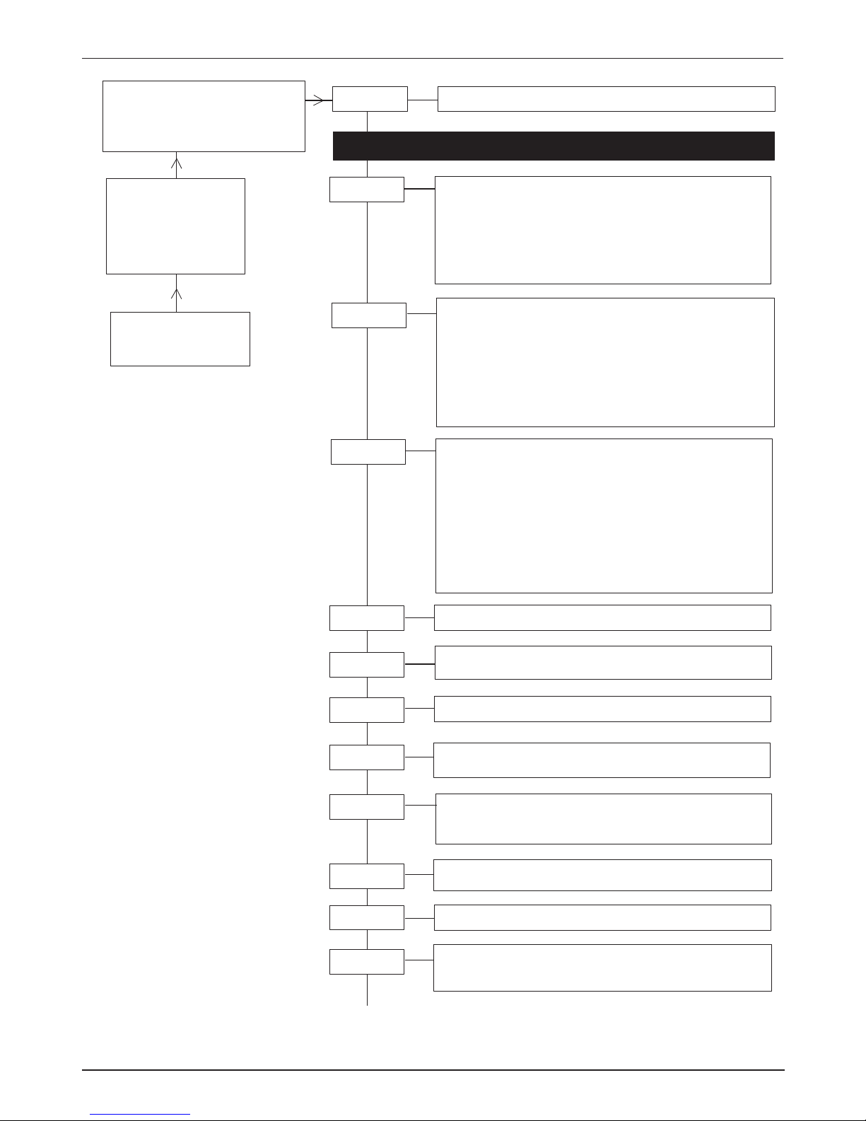
- 33 -
Settings Dual QAM with CI (Key code X061 with transport stream handling)
OV75M A/B=channel
1237MHz=input frequency A/B
479.00=output frequency A/B,
<1.0e-4=BER, alternating display
Channel
OV75M
V1.00
busy
channel
A/B
FE-all: The complete transport stream of the front end
is used
FE-sel: Only programmes selected in the “Prog” menue
are used
ASI-all***: The complete transport stream of the
ASI module OV 67 is used
ASI-sel***: Only programmes selected in the “Prog” menue
are used
Source
OV75M
V1.00
Ch. A
Insert here - input modules settings
F-Out*
Offset**
45-862 MHz,
1MHz steps
4-8 MHz - Offset,
Bsp.:Ch A = 471,25 MHz + 8MHz-Offset=Ch B
loop =
Loop through mode
single
= Single output
1.000-7.499 kBaud
?Symbol rate?
Incorrect symbol rate
?????
refer to note
on/off
on: Signal switched on
off: Signal switched off
OUT-Att*
0-15 dB Output level, 1dB steps
OutConf*
QAMRate
Carrier**
QAMSpec
normal / inverse
16, 32, 64, 128, 256 QAM
type of modulation
QAMMode
(2)
Prog****
Displays the list of transponder name.
Select programme with
.
A * confirms the selected programmes.
Important: Select one programme per channel
If !Overfl. is displayed , (total data rate to high)
reduce the programme numbers.
T=tv
R=radio
#=encrypted
CI
Displays the list of transponder name.
Select the programme to be decrypted with
.
A* confirms the selection.
T=tv
R=radio
#= encrypted
* only at channel A
** only at channel B
*** only with integrated
ASI module OV67
**** only when "FE-sel" or
"ASI-sel" are selected in
the "Source" menue
Operation
Select the menu item and
adjust the values in a menu line
with the UP/DOWN keys .
Enter values and enter and exit
from menu lines with the LEFT/
RIGHT keys .
Exit the second level with .
Saving: Data are saved
automatically. Data are retained
in the case of a power failure.
Page 34
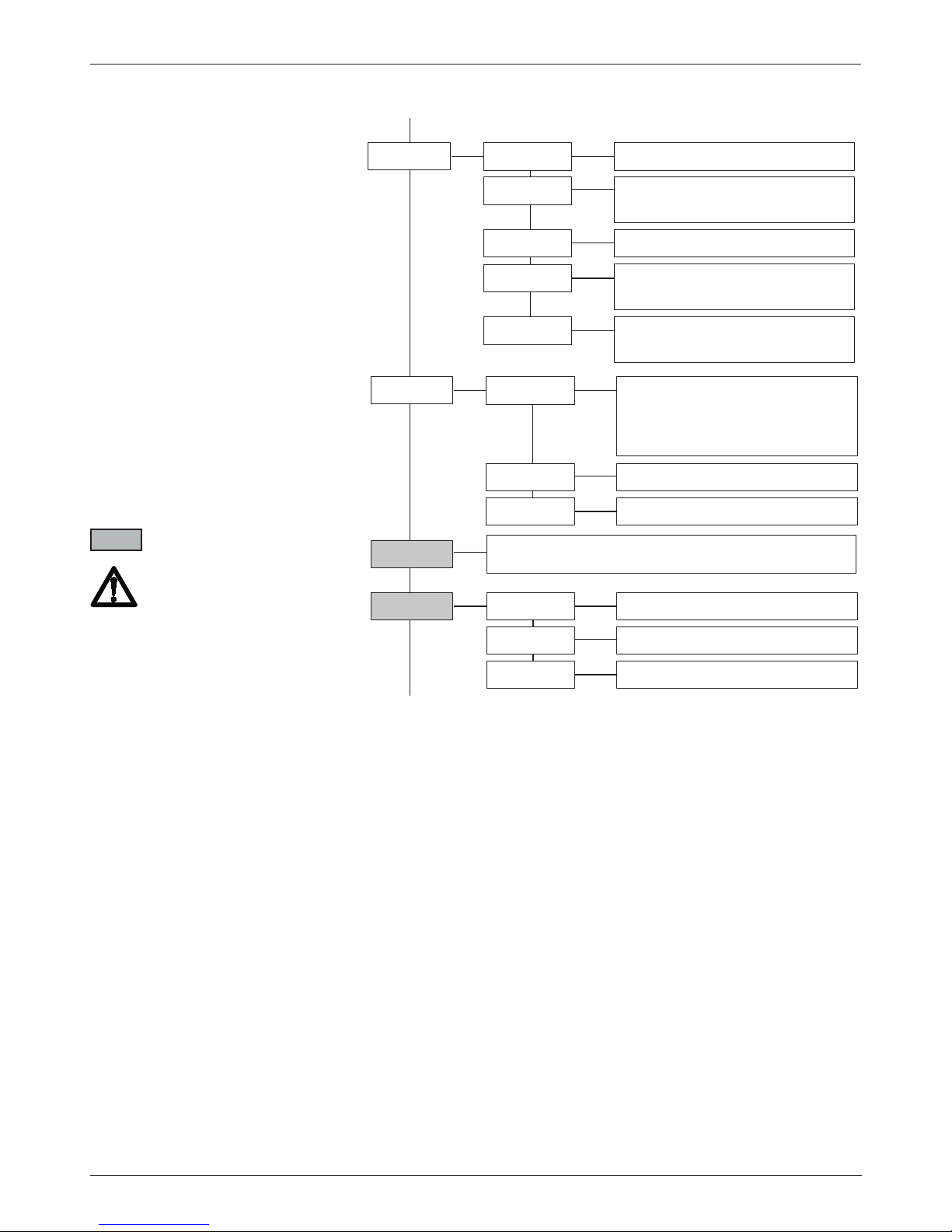
- 34 -
Settings Dual QAM with CI (Key code X061 with transport stream handling)
Op-ID
off or set Hex code 0x000 - 0x1FFF, Operator ID
(1)
PIDFltr
off or Hex-Code 0x000 - 0x1FFF
(1)
PIDFlt0
off or Hex-Code 0x000 - 0x1FFF
...
...
PIDFlt9
PIDAdd****
off or set Hex code 0x000 - 0x1FFF
The entered PID is not filtered
but allowed to pass through
PIDAdd0
off or set Hex code 0x000 - 0x1FFF
PIDAdd9
...
...
NIT-set
on/off Network Information Table
NIT-Gen
network name 7 digits
NETName
off or set Hex code 0x000 - 0x1FFF
Transport Stream Identifier
TSID
off or set Hex code 0x000 - 0x1FFF
Original Transport Stream Identifier
O-NetID
off or set Hex code 0x000 - 0x1FFF
Network Identifier
NetID
Modules with TS handling
B
C
**** only when "FE-sel" or
"ASI-sel" are selected in
the "Source" menue
1) Setting the input frequency:
the "OP-ID" and "PIDFlt turns
to OFF
2) Only for Dual QAM with TS
handling and DVB-S and/or
ASI, DVB-S2 modules
Page 35
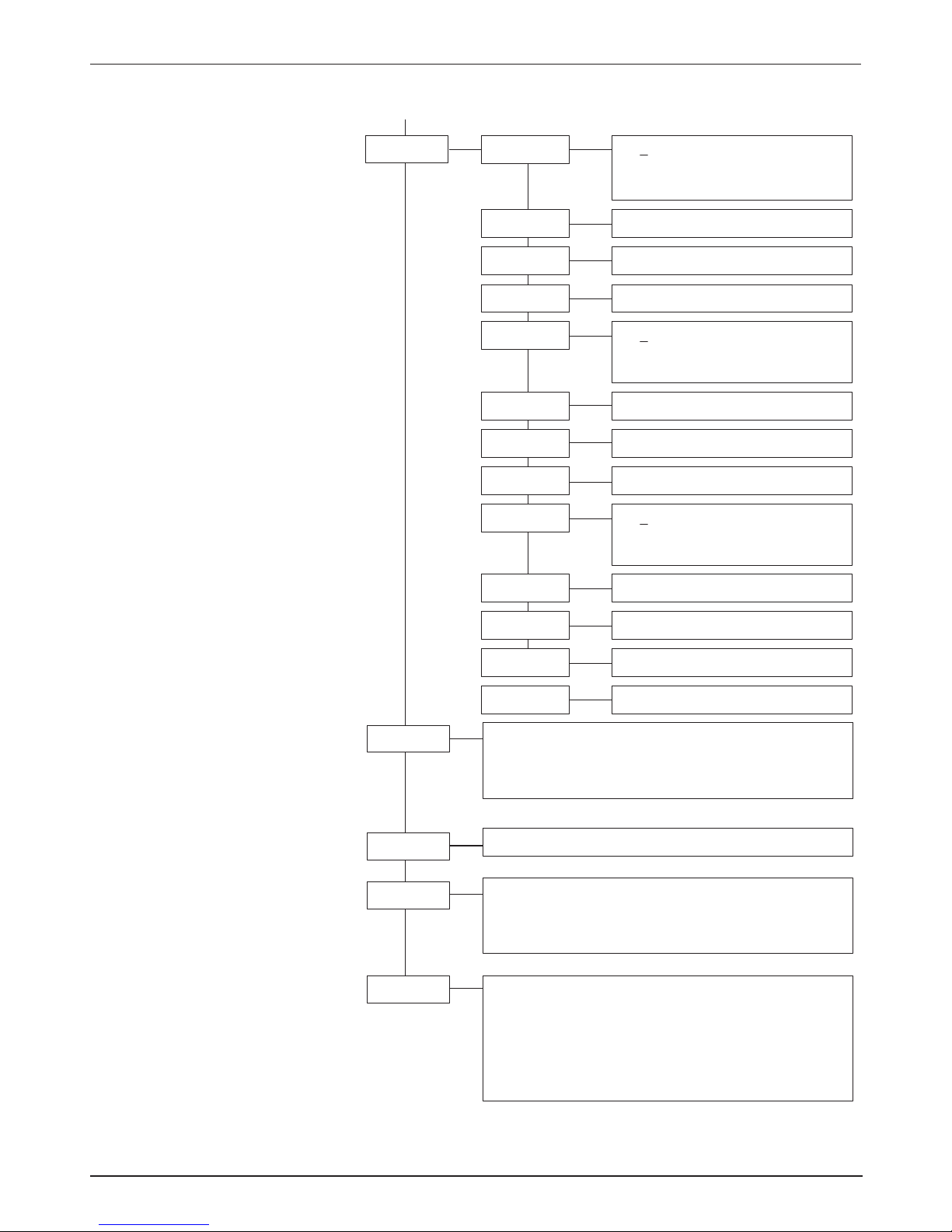
- 35 -
Settings Dual QAM with CI (Key code X061 with transport stream handling)
Modules
Displaying: modules
A: DVBS2
- module
B: -------
- module
Dual-QAM
Mod-No
Displaying: module number
0-9
Version
basic unit version,
software version module
software version QAM module
undocumented command
ModVers
Displaying: hard and software version of input modules
A: DVBS
- module
S1.0003
- software version
H1.0000
- hardware version
M: MPEG2
- module
S1.0003
- software version
H1.0000
- hardware version
Version
V 1.00
1607020
00
IP-sett
172 Move cursor under digit and
select with .
Set IP address
IPAddr0
29 Set IP address
IPAddr1
1 Set IP address
IPAddr2
91 Set IP address
IPAddr3
255 Move cursor under digit and
select with .
Set network mask
Mask0
255 Set network mask
Mask1
0 Set network mask
Mask2
0 Set network mask
Mask3
172 Move cursor under digit and
select with .
Set Gateway address
GWAddr0
29 Set Gateway address
GWAddr1
1 Set Gateway address
GWAddr2
92 Set Gateway address
GWAddr3
00039800000E display MAC address
MACAddr
C
Page 36
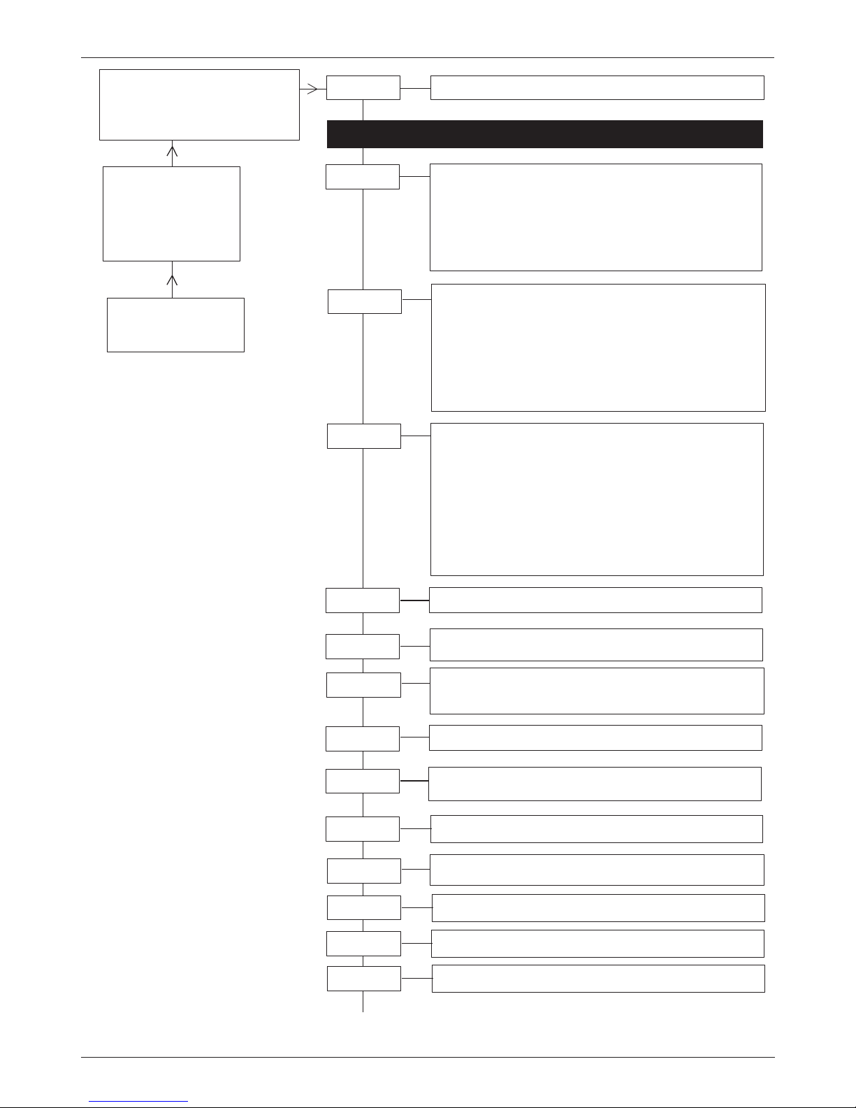
- 36 -
Settings Dual COFDM with CI NonHierarchical mode (Key code X071)
OV75M A/B=channel
1237MHz=input frequency A/B
479.00=output frequency A/B,
<1.0e-4=BER, alternating display
Channel
OV75M
V1.00
busy
Channel
A/B
FE-all: The complete transport stream of the front end
is used
FE-sel: Only programmes selected in the “Prog” menue
are used
ASI-all***: The complete transport stream of the
ASI module OV 67 is used
ASI-sel***: Only programmes selected in the “Prog” menue
are used
Source
OV75M
V1.00
Ch. A
Insert here - input modules settings
F-Out*
Offset**
45-862 MHz,
1MHz steps
4-8 MHz - Offset
Exp.:Ch A = 471,25 MHz + 8MHz-Offset=Ch B
5, 6, 7, 8 MHz = Output bandwith
on/off
on: Signal switched on
off: Signal switched off
OUT-Att*
0-15 dB Output level, 1dB steps
Loop through mode
loop
=
single
= Single output
OutConf*
Out-BW
Carrier**
1/2, 2/3, 3/4, 5/6, 7/8 Code rateHP CR
2k, 8k k-Modek-Mode
16 QAM, 64 QAM, QPSK
QAMMode
type of modulation
Prog****
Displays the list of transponder name.
Select program with
.
A * confirms the selected programmes.
Important: Select one programme per channel
If !Overfl. is displayed , (total data rate to high)
reduce the programme numbers.
T=tv
R=radio
#=encrypted
CI
Displays the list of transponder name.
Select the programme to be decrypted with
A* confirms the selection.
.
T=tv
R=radio
#=encrypted
1/4, 1/8, 1/16, 1/32 Guard intervallGuardin
B
* only at channel A
** only at channel B
*** only with integrated
ASI module OV67
**** only when "FE-sel" or
"ASI-sel" are selected in
the "Source" menue
Operation
Select the menu item and
adjust the values in a menu line
with the UP/DOWN keys .
Enter values and enter and exit
from menu lines with the LEFT/
RIGHT keys .
Exit the second level with .
Saving: Data are saved
automatically. Data are retained
in the case of a power failure.
Page 37
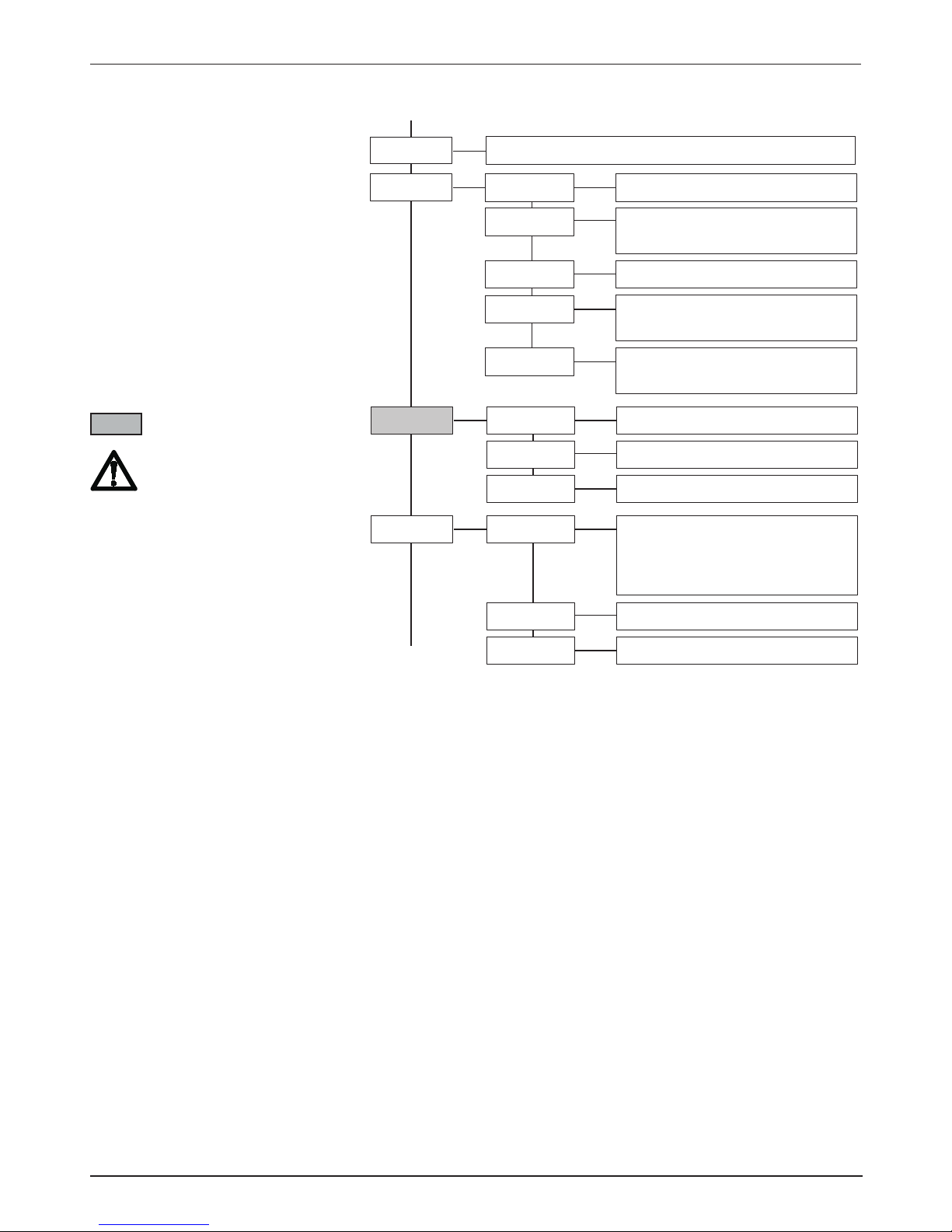
- 37 -
Settings Dual COFDM with CI NonHierarchical mode (Key code X071)
PIDAdd****
off or set Hex code 0x000 - 0x1FFF
The entered PID is not filtered
but allowed to pass through
PIDAdd0
off or set Hex code 0x000 - 0x1FFF
PIDAdd9
...
...
NIT-set
on/off Network Information Table
NIT-Gen
network name 7 digits
NETName
off or set Hex code 0x000 - 0x1FFF
Transport Stream Identifier
TSID
off or set Hex code 0x000 - 0x1FFF
Original Transport Stream Identifier
O-NetID
off or set Hex code 0x000 - 0x1FFF
Network Identifier
NetID
PIDFltr
off or set Hex code 0x000 - 0x1FFF
(1)
PIDFlt0
off or set Hex code 0x000 - 0x1FFF
...
...
PIDFlt9
COFDMSp
normal / inverse COFDM spectrum
C
B
Modules with TS handling
**** only when "FE-sel" or
"ASI-sel" are selected in
the "Source" menue
1) Setting the input frequency:
the "OP-ID" and "PIDFlt turns
to OFF
Page 38
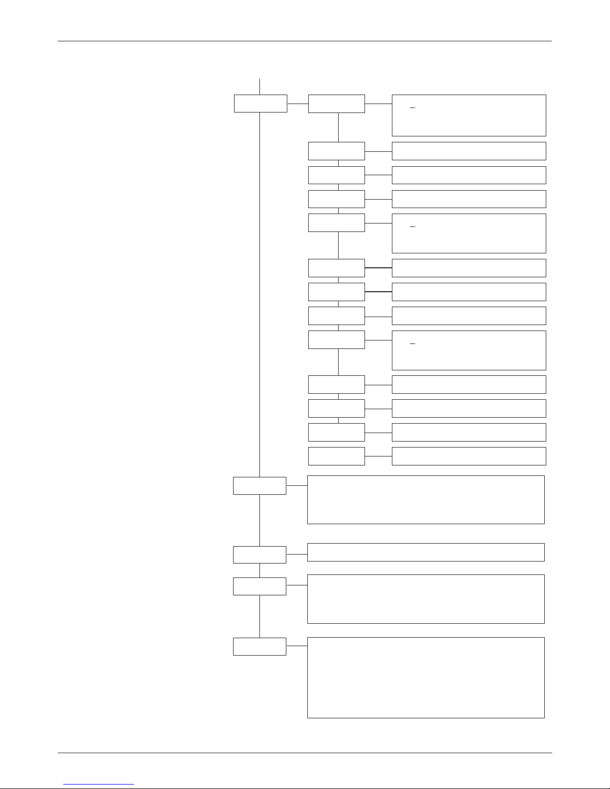
- 38 -
Settings Dual COFDM with CI NonHierarchical mode (Key code X071)
Modules
Displaying: modules
A: DVBS2
- module
B: -------
- module
Dual-QAM
Mod-No
Displaying: module number
0-9
Version
basic unit version,
software version module
software version QAM module
undocumented command
ModVers
Displaying: hard and software version of input modules
A: DVBS
- module
S1.0003
- software version
H1.0000
- hardware version
M: MPEG2
- module
S1.0003
- software version
H1.0000
- hardware version
Version
V 1.00
1607020
00
IP-sett
172 Move cursor under digit and
select with .
Set IP address
IPAddr0
29 Set IP address
IPAddr1
1 Set IP address
IPAddr2
91 Set IP address
IPAddr3
255 Move cursor under digit and
select with .
Set network mask
Mask0
255 Set network mask
Mask1
0 Set network mask
Mask2
0 Set network mask
Mask3
172 Move cursor under digit and
select with .
Set Gateway address
GWAddr0
29 Set Gateway address
GWAddr1
1 Set Gateway address
GWAddr2
92 Set Gateway address
GWAddr3
00039800000E display MAC address
MACAddr
C
Page 39
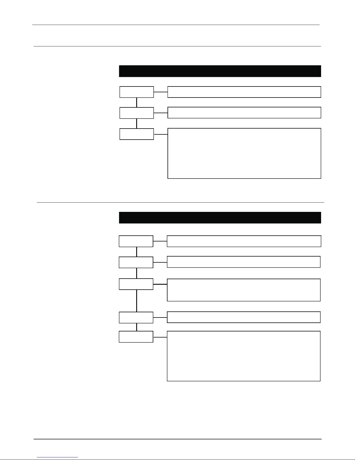
- 39 -
DVB-S module settings
Sat-IF
950-2150 MHz
Selection of Sat-IF, 1 MHz steps
SymRate
BerRate
2.000-45.000 kSps
symbol rate
<1.0 e-4
The BER is an indication of the number of transmission
errors and thus of the signal quality.
<1.0 e-4 = very low numbers of errors
1.0 e-3 = low number of errors
1.0 e-2 = threshold for display:
Signal?
bad signal
41.25 Mb = Input data rate
Sat-IF
950-2150 MHz
Selection of Sat-IF, 1 MHz steps
SymRate
BerRate
2.000-45.000 kSps
symbol rate
<1.0 e-4
The BER is an indication of the number of transmission
errors and thus of the signal quality.
<1.0 e-4 = very low numbers of errors
1.0 e-3 = low number of errors
1.0 e-2 = threshold for display:
Signal?
bad signal
41.25 Mb = Input data rate
DVBmode
S QPSK
- 1/2, 2/3, 3/4, 5/6, 7/8
S2 8QPSK
- 3/5, 2/3, 3/4, 5/6, 8/9, 9/10
S2 QPSK
- 1/2, 3/5, 2/3, 3/4, 4/5, 5/6, 8/9, 9/10
Pilot
on / off
DVB-S2 module settings
GB
Settings DVB-S (Key code 1XXX)
Settings DVB-S2 (Key code 3XXX)
Input modules
Page 40
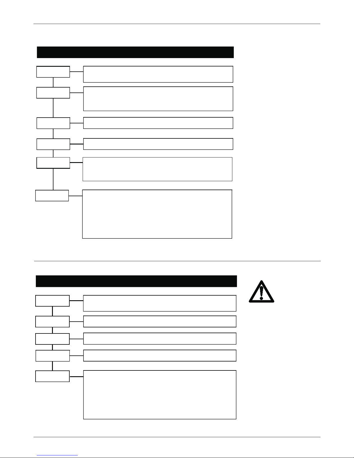
- 40 -
BerRate
<1.0 e-4
The BER is an indication of the number of transmission
errors and thus of the signal quality.
<1.0 e-4 = very low numbers of errors
1.0 e-3 = low number of errors
1.0 e-2 = threshold for display:
Signal?
bad signal
14.46 Mb = Input data rate
In-Freq
146-858 MHz
Selection of input frequency,
0.25 MHz steps
In-Offs
Input offset
-166 kHz, 0, +166 kHz
@
8 MHz
-125 kHz, 0, +125 kHz
@ 7 MHz
In-BW
Bandwidth 7 / 8 MHz
HierMod
Hierarch mode (available from "ModVers: H2.000)
high (Priority)
low (Priority)
In-ATT
0 dB, 20 dB
input attenuator
(available from "ModVers: H2.000)
DVB-T frontend module settings
GB
Channel overload, insert
selective channel filter
into RF input signal
BerRate
<1.0 e-4
The BER is an indication of the number of transmission
errors and thus of the signal quality.
<1.0 e-4 = very low numbers of errors
1.0 e-3 = low number of errors
1.0 e-2 = threshold for display:
Signal?
bad signal
38.15 Mb = Input data rate
In-Freq
50-862 MHz
Selection of input frequency,
0.5 MHz steps
SymRate
1750-7125 kSps
input symbol rate
In-ATT
0 dB, 20 dB
input attenuator
In-Mode
16, 32, 64, 128, 256 QAM
DVB-C frontend module settings
Settings DVB-T (Key code 4XXX)
Settings DVB-C (Key code 5XXX)
Page 41
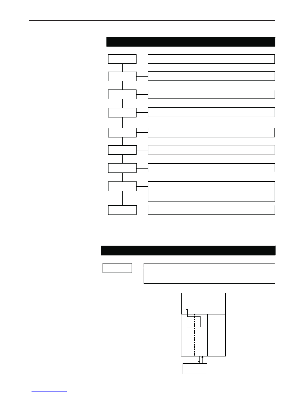
- 41 -
VidRate
3,0: 4,5; 6,0; 9,0
Mbit/s output videodatarate
A-Mode
Stereo, JointSt, Dual, Single
Name
Programme name 7 digits
Provid.
Provider name 7 digits
TP-Gen
on / off
blue screen
TSID
Transport Stream Identifier; settings in HEX code
0 x FFFF
SID
Service Identifier; settings in HEX code
0 x FFFF
VidNorm
PAL, NTSC, SECAM;
Video norm selection
Encode
Aud/Vid
= stored in TV list of the cable receiver
Audio
= stored in Radio list of the cable receiver -
encoding of the audio signal
AV frontend module settings
Settings AV-MPEG (Key code 6XXX)
GB
Settings ASI in/out (Key code 7XXX)
ASI loop
ASI frontend module settings
on /
the ASI module is set in between Frontend and
QAM modulator (ch A). Ch B is set to "off"
off
A
B
DVB-S
ASI
Descrambler
A=
on
QAM
B=
off
Ex: ASI loop: on
Note: Do not use same HEX address
twice.
OV 75 M 6641 with 2 AV front-end
modules
SID mode: set Service identifier in HEX
e.g. AV modul 1 HEX 0x002F
AV modul 2 HEX 0x003F
Page 42
- 42 -
Settings IP 100 Mb (Key code 9XXX)
IPAddr 0
17
2
Move cursor under digit and select with
Set IP address
29
Set IP address
1
Set IP address
Port
0-65535
Set Port address
91
Set IP address
IPAddr 1
IPAddr 2
IPAddr 3
MCAddr 0
MCAddr 1
MCAddr 2
MCAddr 3
MACAddr.
00039800000E
- display MAC address
0.9905 - display FPGA version
MCast
23
9
Move cursor under digit and select with
Set Multicast address
255
Set Multicast address
off/on
Multicast on/off
255
Set Multicast address
255
Set Multicast address
ARPTime
Menue is displayed when Multicast is set to off.
ARPTime: off / adjustable from 2 to 255s.
IP frontend module settings
Page 43
- 43 -
Settings SDI - MPEG (Key code AXXX)
VidRate
3,0: 4,5; 6,0; 9,0
Mbit/s output videodatarate
A-Mode
Stereo, JointSt, Dual, Single
Name
Programme name 7 digits
Provid.
Provider name 7 digits
TP-Gen
on / off
blue screen
TSID
Transport Stream Identifier; settings in HEX code
0 x FFFF
SID
Service Identifier; settings in HEX code 0 x FFFF
Encode
Aud/Vid
= stored in TV list of the cable receiver
Audio
= stored in Radio list of the cable receiver
encoding of the audio signal
Aud-Grp
analogue, 7/8; 5/6; 3/4; 1/2
selection of the audio group
Aud-Vol
-18 ... +18 dB in 6 dB steps
SDI frontend module settings
Note: Do nut use HEX address twice
Page 44

- 44 -
Eingang / Input
Siehe Eingangsmodule / Refer to input modules
QAM modulator
Ausgangskanalbandbreite / Output channel bandwidth 8 MHz
(abhängig von der QAM-Symbolrate / depends on QAM symbolrate)
Ausgangspegel / Output level loop (16-128 QAM) 64–74 dBµV
(256 QAM) 70–80 dBµV
single (16-128 QAM) 74–84 dBµV
(256 QAM) 80–90 dBµV
Ausgangspegelsteller / Output level 1 dB steps 0-10 dB
Modulation / Modulation type 16-, 32-, 64-, 128-, 256-QAM
Symbolrate / Symbol rate 1,0–7,499 MS/s
MER gemessen bei 256 QAM / measurement conditions 256 QAM typ. 42 dB
Filtering Nyquist
√ cos
Roll-off 15 %
Fehlercode / FEC outer code RS (204,188,16)
Spectral inversion normal/inverted
Interleaving Conv., I=12
Nebenaussendungen / Spurious emissions
-innerhalb TV-Kanäle / inside TV-channels > 50 dB
-ausserhalb eines TV-Kanals / outside a TV-channel > 50 dB
COFDM modulator
Output channel bandwidth 5, 6, 7, 8 MHz
Output level loop 58 – 74 dBµV
single 68 – 84 dBµV
Output attenuation 1 dB steps 0-16 dB
Modulation QPSK, QAM 16, QAM 64
MER > 36 dB
FEC 1/2, 2/3, 3/4, 5/6, 7/8
Guard interval 1/4, 1/8, 1/16, 1/32
FFT mode 2k, 8k
Shoulder attenuation > 50 dB
Standard compliance
- ETSI EN 300744 V1.51 Digital Video Broadcasting (DVB); Framing structure, channel
coding and modulation for digital terrestrial television
Ausgang / Output
Ausgangsimpedanz / Output impedance 75 Ohm
Ausgangsfrequenz / Output frequency (ch A) 45 –862 MHz
Abstimmschritte / Output frequency steps (ch A) 250 kHz
Kanalabstand A-B / Offset (ch A - B) 1 MHz steps 4–8 MHz
nur bei Dual-QAM / only in Dual QAM mode
Rückflußdämpfung / Return loss > 14 dB
Technische Daten Dual-QAM Modul / Specifications Dual-QAM module
Page 45

- 45 -
Technische Daten REMUX-QAM Modul / Specifications REMUX-QAM module
Eingang / Input
Siehe Eingangsmodule / Refer to input modules
QAM-Ausgang / QAM output
Ausgangsimpedanz / Output impedance 75 Ohm
Ausgangsfrequenz / Output frequency (ch A) 45–862 MHz
Abstimmschritte / Output frequency steps (ch A) 250 kHz
Bandbreite / Bandwidth
(abhängig von der QAM-Symbolrate / depends on QAM symbolrate)
Ausgangspegel / Output level loop (16-128 QAM) 64–74 dBµV
(256 QAM) 70–80 dBµV
single (16-128 QAM) 74–84 dBµV
(256 QAM) 80–90 dBµV
Ausgangspegelsteller / Output level 10 dB
- Einstellschritte / Output level steps 1 dB
Rückflußdämpfung / Return loss > 14 dB
Modulation / Modulation type 16-, 32-, 64-, 128-, 256-QAM
Symbolrate / Symbol rate 1,0–7,499 MS/s
MER gemessen bei 256 QAM / measurement conditions 256 QAM typ. 43 dB
Filtering Nyquist
√ cos
Roll-off 15 %
Fehlercode / FEC outer code RS (204,188)
Spectral inversion normal/inverted
Interleaving Conv., I=12
Nebenaussendungen / Spurious emissions (45-862 MHz) > 50 dB
Ausgang / Output
Ausgangsimpedanz / Output impedance 75 Ohm
Ausgangsfrequenz / Output frequency (ch A) 45 –862 MHz
Abstimmschritte / Output frequency steps (ch A) 250 kHz
Rückflußdämpfung / Return loss > 14 dB
Page 46

- 46 -
QPSK-Eingang / Input
Eingangsimpedanz / Input impedance 75 Ohm
Eingangsfrequenz / Input frequency 950–2150 MHz
Abstimmschritte / Input frequency steps 1 MHz
Eingangspegel / Input level 44-84 dBµV
Modulationsart / Type of modulation QPSK
Fehlerkorrektur / FEC 1/2, 2/3, 3/4, 5/6, 7/8
Symbolrate / Symbol rate 2–45 MS/s
Transportstrom-Ausgang / Transport stream output
Technische Daten DVB-S Modul / Specifications DVB-S module
QPSK-Eingang / Input
Eingangsimpedanz / Input impedance 75 Ohm
Eingangsfrequenz / Input frequency 950–2150 MHz
Abstimmschritte / Input frequency steps 1 MHz
Eingangspegel / Input level 47-70 dBµV
Modulationsart / Type of modulation DVB-S QPSK
DVB-S2 QPSK / 8 QPSK
Fehlerkorrektur / FEC DVB-S 1/2, 2/3, 3/4, 5/6, 7/8
DVB-S2 1/4, 1/3, 2/5, 1/2, 3/5, 2/3,
3/4, 4/5, 5/6, 8/9, 9/10
Symbolrate / Symbol rate DVB-S 2–45 MS/s
DVB-S2 10-30 MS/s
Transportstrom-Ausgang / Transport stream output
Technische Daten DVB-S2 Modul / Specifications DVB-S2 module
DVB-T-Eingang / Input
Eingangsimpedanz / Input impedance 75 Ohm
Eingangsfrequenz / Input frequency 146–858 MHz
Abstimmschritte / Input frequency steps 0,25 MHz
Bandbreite / Bandwidth 7 / 8 MHz
Frequenz-Offset / Frequency offset 8 MHz + 166 kHz
7 MHz + 125 kHz
Eingangspegel / Input level 40-90 dBµV
Modulationsart / Type of modulation QPSK, 16, 64 QAM
COFDM 2k-FFT, 8k-FFT
Guard intervall 1/4, 1/8, 1/16, 1/32
Fehlerkorrektur / FEC 1/2, 2/3, 3/4, 5/6, 7/8
Transportstrom-Ausgang / Transport stream output
Technische Daten DVB-T Modul / Specifications DVB-T module
Page 47

- 47 -
Video-Eingang / Video input
Eingangsimpedanz / Input impedance 75 Ohm
Eingangsformat / Input format Composite PAL
Eingangspegel / Input level 1 Vpp
Encoder-Standard / Encoding Standard ISO / IEC 13818-2
MP@ML (4:2:0)
Bitrate / Bit rate 1,5 Mbit/s-9 Mbit/s
Unterstützte Auflösung / Supported resolutions Full D1
Betriebsart / Operation mode CBR, VBR
Audio-Eingang / Audio input
Eingangsformat / Input format Analog (left, right) 83-9
Eingangspegel / Input level 0 dBm / 600 Ohm
Abtastrate / Sampling frequency 48 kHz
Encoder-Standard / Encoding Standard MPEG1 Layer 2
Bitrate / Bit rate 192 kbit/s
Entzerrung / Emphasis none
Betriebsart / Mode stereo, join stereo, dual, single channel
Technische Daten AV Modul / Specifications AV module
Eingang / Input
Eingangsimpedanz / Input impedance 75 Ohm
Eingangsfrequenz / Input frequency 50–862 MHz
Abstimmschritte / Input frequency steps 0,5 MHz
Eingangspegel / Input level 45-90 dBµV
- Dämpfungssteller auf 20 dB geschaltet / Attenuator set to 20 dB 65-110 dBµV
Eingangsdämpfungssteller schaltbar / Input signal attenuator 0 dB / 20 dB
Modulationsart / Type of modulation 16, 32, 64, 128, 256-QAM
Symbolrate / Symbol rate 1.75–7.125 MS/s
Transportstrom-Ausgang / Transport stream output
Technische Daten DVB-C Modul / Specifications DVB-C module
Page 48

- 48 -
ASI-Transmitter
LVTTL - Eingang / LVTTL input
Datenformat / Data format DVB-SPI (LVTTL), EN50083-9
Packete / Packet framing 188 / 204 byte per packet
ASI-Ausgang / ASI output
Datenformat / Data format DVB A010 ASI-C, EN50083-9
Packete / Packet framing 188 / 204 byte per packet
Bitrate 270 Mb/s
ASI-Betriebsart / ASI mode Burst
Signalpegel / Signal level 800mV (p-p)
Deterministic jitter 10%
ASI-Eingang / ASI input
Eingangsimpedanz / Input impedance 75 Ohm
Datenformat / Data format DVB A010 ASI-C, EN50083-9
Bitrate 270 Mb/s
ASI-Betriebsart / ASI mode Burst or continuous
Packete / Packet framing 188 / 204 byte per packet
Empfindlichkeit / Sensitivity 200mV (p-p)
Max. Signalpegel / Max. signal level 880mV(p-p)
Eingangs-Rückflussdämpfung / Input return loss > 17 dB (27-270 MHz)
LVTTL-Ausgang / output
Datenformat / Data format DVB-SPI (LVTTL), EN50083-9
Packete / Packet framing 188 / 204 byte per packet
Technische Daten ASI-Modul / Specifications ASI module
Technische Daten IP-Modul / Specifications IP module
Ethernet-Eingang / Ethernet input
Interface 10/100 Base (RJ45)
Frame Format Ethernet II
Rate 10/100 Mbps autosensing
Protokoll / Protocol UDP/IP, ARP, ICMP(ping), IGMPv2
Ethernet Übertragung / Ethernet tansmitting Unicast, Multicast
Page 49

- 49 -
Technische Daten SDI-Modul / Specifications SDI module
Video-Eingang / Video input
Eingangsformat / Input format SDI SMPTE 259M-C 270Mb/s 625Z
with embedded audio SMPTE 272M-A
Eingangspegel / Input level 200 mVpp ohne / without equalizer
Eingangsimpedanz / Input impedance 75 Ohm
Encodingstandard / Encoding standard MPEG 2 ISO/IEC 13818-2
MP@ML (4:2:0)
Bitrate / Bit rate 1,5 Mbit/s up to 9 Mbit/s
Unterstütze Auflösungen / Supported resolutions Full D1
Bildgröße / Frame format horizontal/vertical 720/576 pixel
Audio-Eingang / Audio input
Eingangsformat / Input format Analog (left,right) or digital (SDI with
embedded Audio)
Eingangspegel / Input level 0 dBm / 600 Ohm
Encodingstandard / Encoding standard MPEG 1 L1/2 ISO/IEC 13818-3
Bitrate / Bit rate up to 192 kbit/s
Emphasis keine / none
Audiomode stereo, joint stereo, dual, single
Abtastfrequenz / Sampling frequency 48 kHz
Transportstrom-Ausgang / Transport stream output
Stream type MPEG 2 transport stream
Elementary streams Video. Audio,
System multiplexing ISO/IEC 13818-1
Tabellen / Tables PAT, PMT
System Bitrate / System bit rate 1,6875 … 13,5 MB/s
Betriebsart / Operation mode CBR, VBR
Allgemeines / General
Gehäuse / Housing Zinkdruckguss / Zinc die-cast
Abmessungen / Dimensions 30 x 260 x 200 mm
Anschlüsse / Sockets HF-Ein-Ausgang / RF input and output F-type
Betriebsspannung / Operating voltage 5,2 VDC / 1350 mA max.*
12,5 VDC / 400 mA max.*
Betriebstemperaturbereich / Operating temperatur range 0°C ... +50°C
Lagertemperatur / Storage temperatur -25°C ...+75°C
Max. Luftfeuchte, nicht kondensierend / Max. humidity, non condensing 95%
EMV / EMC EN 50083-2
*je nach Konfiguration
dep. on config
Page 50

- 50 -
Beispiel / Example
OV 75 M 11 21 = 2 x DVB-S Dual-QAM
OV 75 M 44 11 = 2 x DVB-T Remux-QAM
OV 75 M 47 11 = DVB-T / ASI Remux-QAM
OV 75 M 66 41 = 2x AV-Encoder Remux-COFDM
OV 75 M 40 41 = DVB-T-COFDM Repeater
0 - n.a.
1 - DVB-S
2 - n.a.
3 - DVB-S2
4 - DVB-T
5 - DVB-C
6 - AV-MPEG
7 - ASI - Input/Output
8 - n.a.
9 - Ethernet - Input (IP)
A - SDI - MPEG
1 - Remux QAM
2 - Dual QAM (with transportstream handling*)
3 - Dual QAM (without transportstream handling)
4 - Remux COFDM
6 - Dual QAM (with CI, NIT and Service-Filter)
7 - Dual COFDM (with CI, NIT and Service-Filter)
O V 7 5 M x x x 1
Kanalschlüssel
Key code
Ausgang
Output
Eingang
Input
1 2
Option 1
Bestellinformationen / Ordering informations
Hinweis: *SI table editor mit CS 76 (separat bestellen)!!
Note: SI table editor with CS 76 (Order separately)
Bestellbeispiele / Ordering samples
Remux QAM
Eingangsmodule slot 1/2
Input modules slot 1/2
7111 ASI In,Out / DVB-S
7611 ASI In,Out / AV-MPEG
7711 ASI In,Out / ASI In/Out
6611 AV-MPEG / AV-MPEG
5311 DVB-C / DVB-S2
5511 DVB-C / DVB-C
5611 DVB-C / AV-MPEG
1111 DVB-S / DVB-S
1411 DVB-S / DVB-T
1611 DVB-S / AV-MPEG
1711 DVB-S / ASI In/Out
3011 DVB-S2 / —
3111 DVB-S2 / DVB-S
3711 DVB-S2 / ASI In/Out
4411 DVB-T / DVB-T
4511 DVB-T / DVB-C 4611
9511 Ethernet In (IP) / DVB-C
Dual QAM + NIT
Eingangsmodule slot 1/2
Input modules slot 1/2
7021 ASI In,Out / —
6621 AV-MPEG / AV-MPEG
6721 AV-MPEG / ASI In/Out
7621 ASI In/Out / AV-MPEG
7721 ASI In,Out / ASI In/Out
5021 DVB-C / —
5521 DVB-C / DVB-C
5721 DVB-C / ASI In,Out
1021 DVB-S / —
1121 DVB-S / DVB-S
1321 DVB-S / DVB-S2
1421 DVB-S / DVB-T
1721 DVB-S / ASI In/Out
3021 DVB-S2 / —
3721 DVB-S2 / ASI In/Out
4021 DVB-T / —
4421 DVB-T / DVB-T
4721 DVB-T / ASI In,Out
9121 Ethernet In (IP) / DVB-S
9421 Ethernet In (IP) / DVB-T
9721 Ethernet In (IP) / ASI
In, Out
9921 Ethernet In (IP) / Ethernet
In (IP)
Page 51
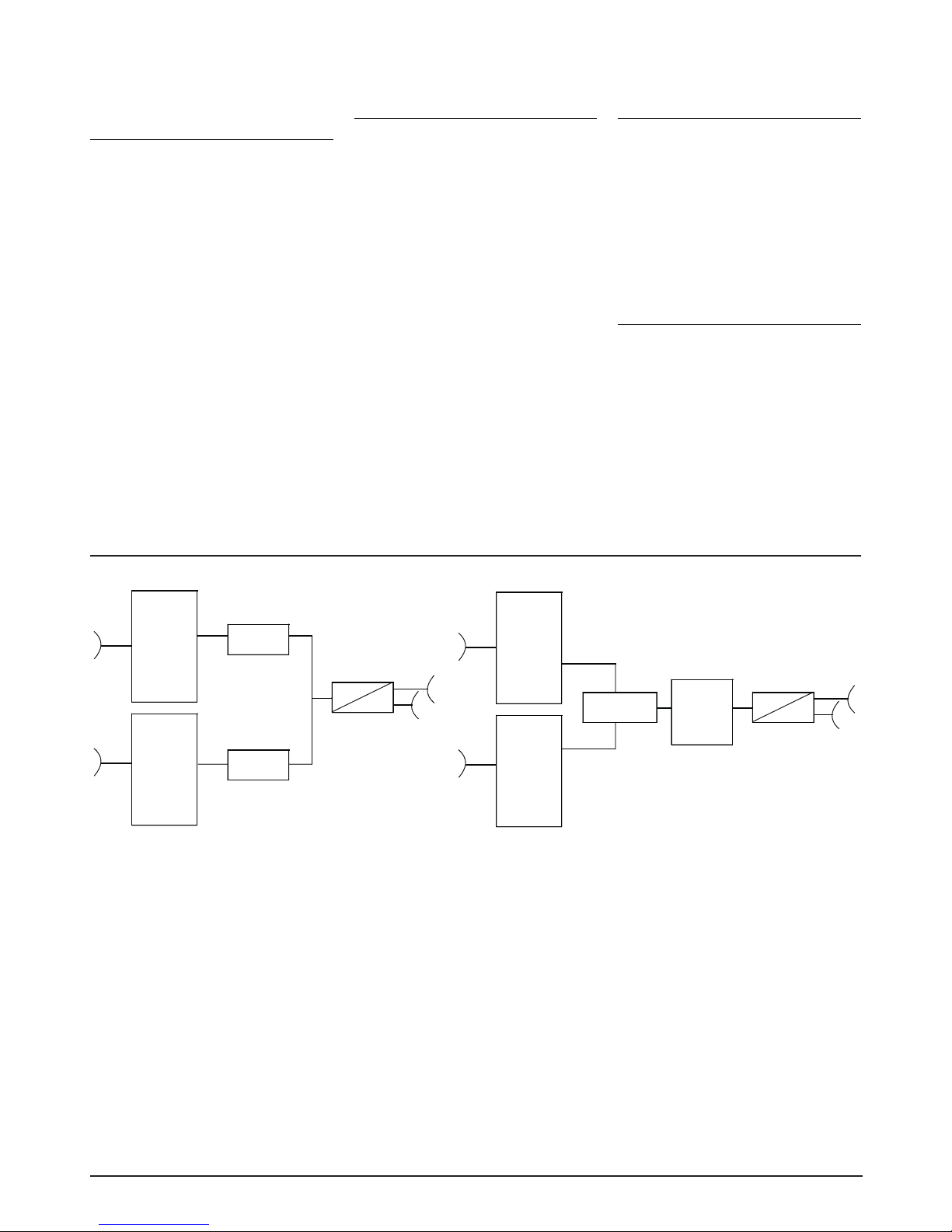
- 51 -
Dual QAM ohne / without
NIT
Eingangsmodule slot 1/2
Input modules slot 1/2
7731 ASI In,Out / ASI In/Out
1131 DVB-S / DVB-S
3031 DVB-S2 / —
Remux COFDM
Eingangsmodule slot 1/2
Input modules slot 1/2
7041 ASI In/Out / —
7741 ASI In,Out / ASI In,Out
9741 Ethernet In (IP) / ASI In,
Out
1041 DVB-S / —
1141 DVB-S / DVB-S
3141 DVB-S2 / DVB-S
4041 DVB-T / —
(
COFDM Repeater)
4441
DVB-T / DVB-T
AA41 SDI / SDI
Dual QAM mit/with CI
Eingangsmodule slot 1/2
Input modules slot 1/2
3061 DVB-S2 / —
4061 DVB-T / —
5061 DVB-C / —
9061 Ethernet In (IP) / —
Dual COFDM mit/with CI
Eingangsmodule slot 1/2
Input modules slot 1/2
3071 DVB-S2 / —
4071 DVB-T / —
5071 DVB-C / —
9071 Ethernet In (IP) / —
Blockdarstellung / Block diagram
DVB - S
DVB - S2
DVB - T
ASI
IP
AV
SDI
DVB - S
DVB - S2
DVB - T
ASI
IP
AV
SDI
QAM
Modulator
*
*
QAM
Modulator
IF
RF
DVB - S
DVB - S2
DVB - T
ASI
IP
AV
SDI
DVB - S
DVB - S2
DVB - T
ASI
IP
AV
SDI
Multiplexer
*
*
QAM
or
COFDM
Modulator
IF
RT
*Required front end:
please specify with your order
*Required front end:
please specify with your order.
1xDVB-T input module is required for
Repeater mode.
Note: 2x DVB-S2 - no application
Page 52
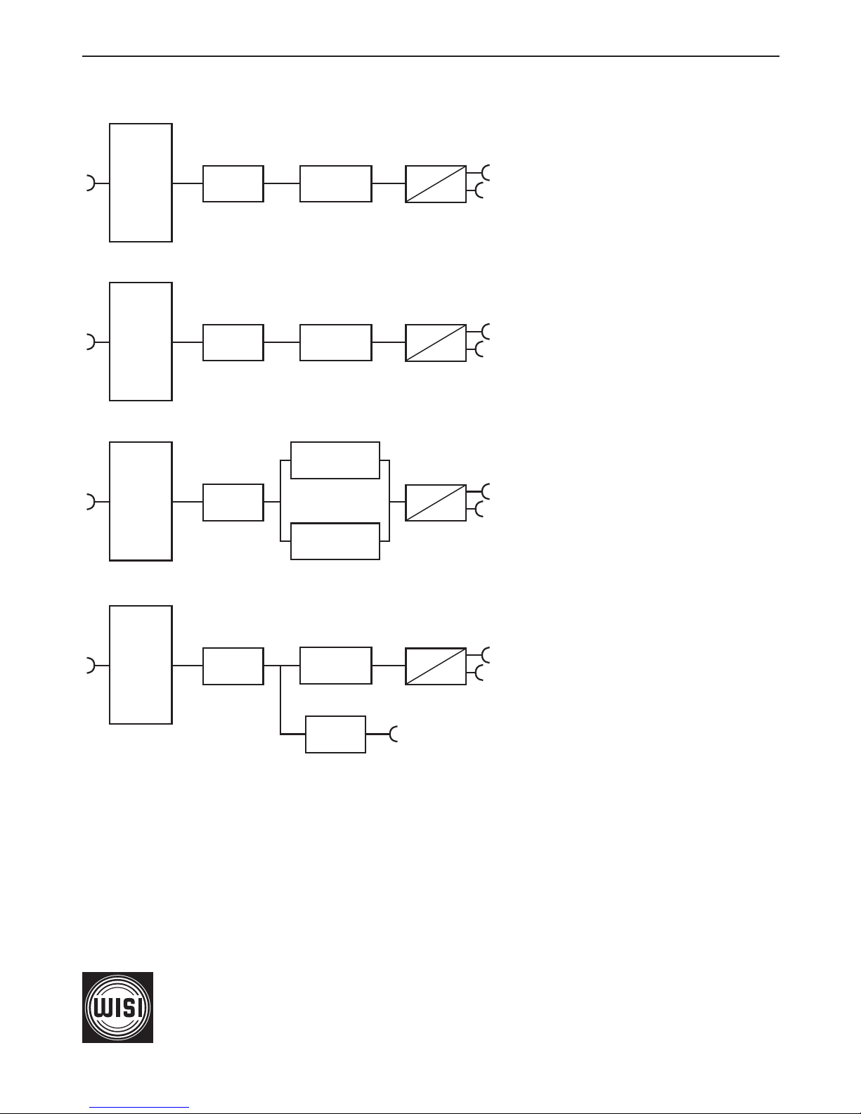
- 52 -
06/10
WISI Communications GmbH & Co. KG
Empfangs- und Verteiltechnik
Wilhelm-Sihn-Straße 5-7, 75223 Niefern-Öschelbronn
Tel . 07233 / 66-0, Fax. 66-320, http://www.wisi.de
Technische Änderungen und Druckfehler vorbehalten!
Technical Modifications reserved. WISI cannot be held
liable for any printing error.
excellence in digital ...
QAM
Modulator
COFDM
Modulator
...
Modulator
OV 75 M CI
IF
RF
Common
Interface
IF
RF
Common
Interface
IF
RF
Common
Interface
IF
RF
Common
Interface
COFDM/QAM
Modulator
COFDM/QAM
Modulator
OV 67
ASI out
DVB - S2
DVB-T/C
IP
DVB - S2
DVB-T/C
IP
*
*
*
*
DVB - S2
DVB-T/C
IP
DVB - S2
DVB-T/C
IP
Blockdarstellung mit CI / Block diagram with CI
*Required front end:
please specify with your order
 Loading...