

Page 1
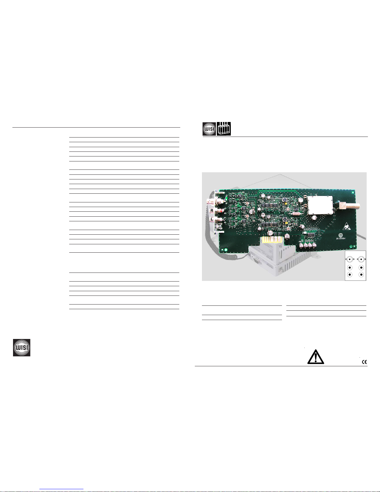
Betriebsanleitung
Operating instructions
WISI MINI HEADEND
OM 10 TWIN AV-Modulator stereo / TWIN AV modulator stereo
045 093
Modulation von zwei Video- und Audiosignalen
in den Frequenzbereich 470 -862 MHz
Bis zu 12 Kanäle mit 6 Twin-Modulatoren
möglich
Einstellungen über Handset OK 41A
Modulation of two video- and audio signals into
the frequency range of 470 -862 MHz
Modulation of max. 12 ch via 6 Twin modulators
Settings via handset OK 41A
R
L
A
B
WISI Communications GmbH & Co. KG
Empfangs- und Verteiltechnik
Wilhelm-Sihn-Straße 5-7, 75223 Niefern-Öschelbronn
Tel . 07233 / 66-292, Fax. 66-320, http://www.wisi.de
Video / Video
Impedanz / Impedance 75 Ω
Videopegel / Video level 1 Vss
Einstellbereich / Tuning steps 1-dB-Schritte / steps -6 dB...+6 dB
Videobandbreite / Video bandwidth 20 Hz – 5 MHz
S/N, (CCIR-rec.567-1) >52 dB, typ.54 dB
Audio / Audio
Impedanz / Impedance 600 Ω / 20 kΩ
Audiopegel / Audio level 500 mVeff
Einstellbereich / Tuning steps 3-dB-Schritte / steps -6 dB...+6 dB
Frequenzbereich / Frequency range 40 Hz-15 kHz
S/N (mit Farb-Testbild) / S/N (with color test pattern) >45 dB
Ausgang / Output
Impedanz / Impedance 75 Ω
Frequenz / Frequency 470 – 862 MHz
Einstellbereich / Tuning steps 250-kHz-Schritte / steps
Modulation / Modulation Zwei-Seitenband / Double sideband
Nebenaussendungen innerhalb AM-TV Kanal / inside AM-TV channel > 60 dB
Nebenaussendungen ausserhalb TV-Kanal / outside a TV channel > 56 dB
Pegel pro Kanal / Level per channel 78 dBµV
TV-Standard / TV standard *stereo B/G*, D/K*, M, I, L
Testbild-Generator / Test pattern generator s/w; black/white
Allgemeine Daten / General datas
Anschlüsse / Connectors
- HF-Ausgang / RF output F
- Video
BNC
- Audio
Rot / red R-ch
Cinch
weiß / white L-ch
Betriebsspannungen / Operating voltages 3.3 V DC 7 mA
5 V DC 180 mA
Leistungsaufnahme / Power consumption < 1 W
Betriebstemperaturbereich / Operating temperature 0°C ... +55°C
Lagertemperatur/ Storage temperatur -25°C ... +75°C
Max. Luftfeuchte nicht kondensierend / 95 %
Max. humidity non condensing
Abmessungen / Dimensions 90 x 200 x 33 mm
... a link to the future
Technische Daten / Specifications
02/06
Servicearbeiten / Service work
Dürfen nur von autorisiertem Fachpersonal durchgeführt werden.
Service work may be carried out only by qualified personnel.
Video
Audio
Technische Änderungen und Druckfehler vorbehalten!
Technical Modifications reserved. WISI cannot be held
liable for any printing error.
Page 2
OUT 470-862 MHz
IN-4
Netzteil
Power supply
Alimentation
IN-1 +5VDC 110mA
Module anschrauben
Tighten moduls
230 VAC
(A) (A)
Modul 1
OM 10
IN-6
Modul 3
Modul 4
Modul 5
Modul 6
IN-2
Gain
Adj.
IN-3 IN-5
Modul 2
OM 10
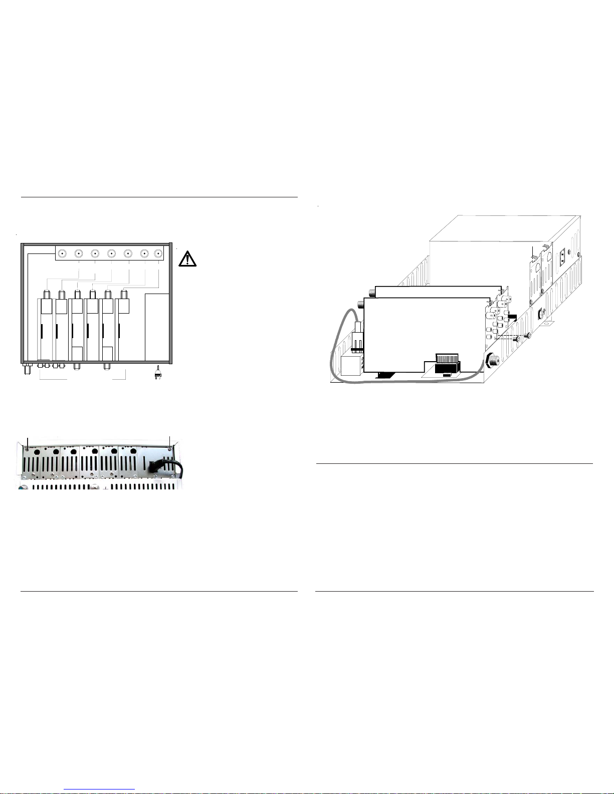
Einbau Modul / Installation of module
Werkseitige Einstellungen/ Factory settings
Videopegel / Video level 0 dB
Audiopegel / Audio level 0 dB
TV standard B/G (Stereo)
Ausgangskanal / Output ch Kanal A = ch 21
Kanal B = ch 23
Spannungsfrei schalten!
Switch off power supply!
Deckel
Die zwei oberen Kreuzschlitzschrauben (A) entfernen. Deckel leicht nach hinten schieben und abnehmen.
Cover
Unscrew the two upper Philips screws (A). Lift up the cover and remove.
(A)
(A)
Modul eindrücken; anschrauben und anschliessen.
Insert the module into the slot and press down. Tighten and connect it.
Teilbestückung / Partial assembly
Hinweis: bei Teilbestückung, (z.B. 3 Module), darauf achten, daß der Modulplatz 1+2 bestückt sind, da
über diese Modulplätze der Ausgangssammelverstärker mit Betriebsspannung versorgt wird.
Note: Please make sure that slot number 1+2 of the basic unit is equipped with a module (OM 14...
17) in any case (particularly if not all slots are to be used) because this first slot feeds the
booster amplifier of the base unit.
Modul 1
Modul 2
Anschluß / Connection
Page 3
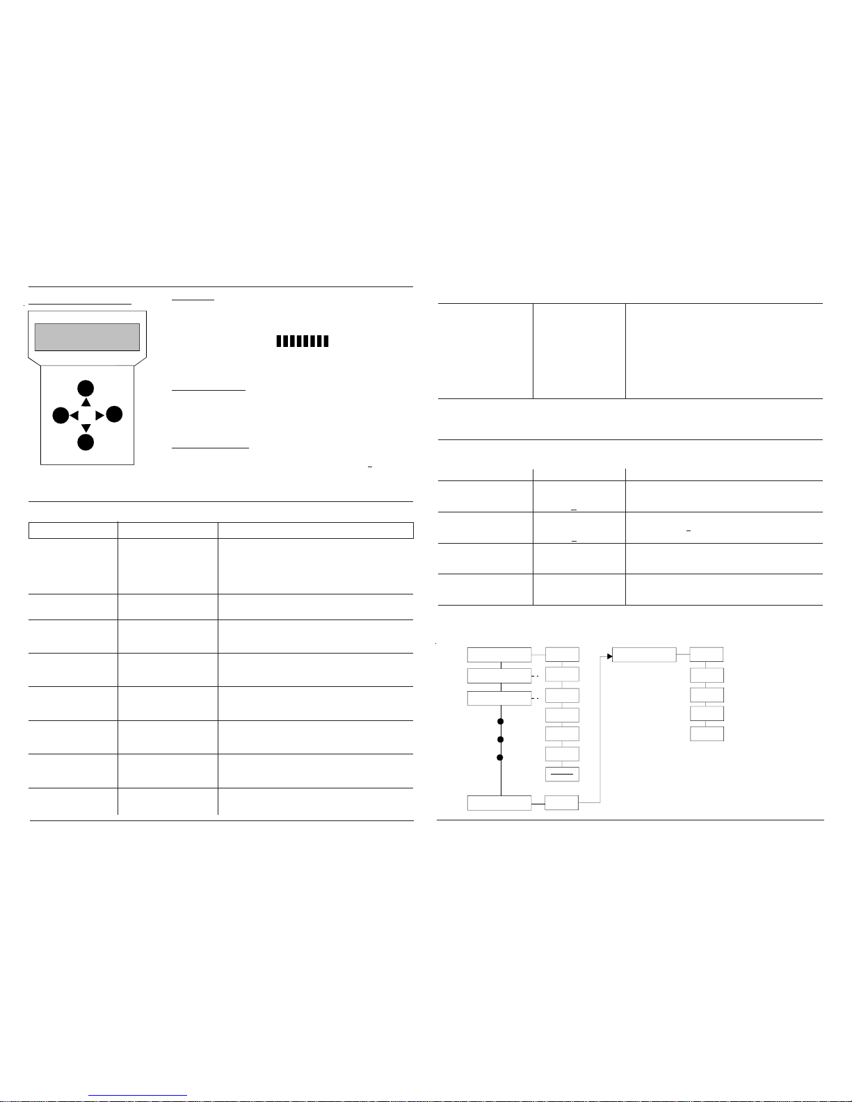
Parameter settings with handset
Operation Display Settings
Select modul 1-6 Example Two modules OM 10 are displayed with
two separate inputs.
Modul 1 1 OM 10 Ch 42 Input (A) – Output ch. 42
1 OM 10 Ch 44 Input (B) – Output ch. 44
Modul 2 2 OM 10 Ch 46 Input (A) – Output ch. 46
2 OM 10 Ch 48 Input (B) – Output ch. 48
Audio impedance AudImp Select with UP/DOWN buttons and confirm
600 Ohm, 20 kOhm 600 Ohm with R button.
Audio level AudLev Select with UP/DOWN buttons and confirm
-6 dB...+ 6 dB 0 dB (3 dB steps) with R button.
Video level VidLev Select with UP/DOWN buttons and confirm
-6 dB...+ 6 dB 0 dB (1 dB steps) with R button.
Test pic TstPic: off off=test picture
off / sw s/w=black/white bars with 1 kHz signal ton
TV standard
TV-Std: BG Ster Select with UP/DOWN buttons and confirm
B/G*, D/K*, M, I, L with R button. *B/G,*D/K = Stereo
Output channel/freq OutFreq: Ch 42 Select channel/freq. (refer to system parameters)
ch 21-69
Connection
Plug the handset into socket .
Connect the supply voltage.
Display shows information WISI OM Startup.
Press any button. „Search modules“with rotating „\“ is displayed.
Display shows the modules:
1 OM 10 Ch 42
1 OM 10 Ch 44
Operation selection
ST keys — Select Operation.
X ke y — Open sub-menu.
W ke y — Back to operation. Select with buttons
ST
next operation.
Parameter sub-menu
WX keys — Select display or value to be changed.
Cursor stands under the value, e.g.
89
ST keys — Change the value.
Left
Right
Down
Up
WISI OM V1.00
Mini Headend
Handset
System settings
System settings 3 OM 10 Ch 52 Select with UP/DOWN buttons to „System
System settings settings“ as ex. 3 modules OM 10:
1 OM 10 Ch 42
1 OM 10 Ch 44
2 OM 10 Ch 46
2 OM 10 Ch 48
3 OM 10 Ch 50
3 OM 10 Ch 52
System settings
Not required by outfitting with modules OM 10 or 11
LNB settings LNBSet System Select with UP/DOWN buttons.
Ch/Frq settings
LNB power System Settings Select with UP/DOWN buttons.
14V 0kHz, 14V -22 kHz LNBSet: 14V 0kHz
18V 0kHz, 18V -22 kHz
Output frequency
System Settings Select with UP/DOWN buttons: Display
Channel / Freq. Ch/Frq: Channel channel or frequency.
Output Attenuator
System Settings Move cursor with L/R keys to digit to be
0...10 dB OutAtt: 3 changed and adjusted with UP/DOWN keys.
Software-Version Sw-Ver Module1 Select with UP/DOWN buttons and confirm
(only displayed) with R button.
Hardware-Version Hw-Ver Module1 Select with UP/DOWN buttons and confirm
(only displayed) with R button.
Handset OK... (Accessory)
First Start-Up of basic unit OM 01: Set "System settings" first
Modul 1
Modul 2
Modul 3
Modul 4
Modul 5
Modul 6
1 OM 10 Ch 42
1 OM 10 Ch 44
2 OM 10 Ch 46
2 OM 10 Ch 48
3 OM 10 Ch 50
3 OM 10 Ch 52
System-Settings
Audimp
AudLev
VidLev
TstPic
TV-Std
OutFreq
LNBSet
Ch/Frq
OutAtt
SW-Ver
HW-Ver
LNBSet
System-Settings
SW-Ver
HW-Ver
Main menu
Parameter
menu
Main menu
Parameter
menu
Menu structure
Page 4
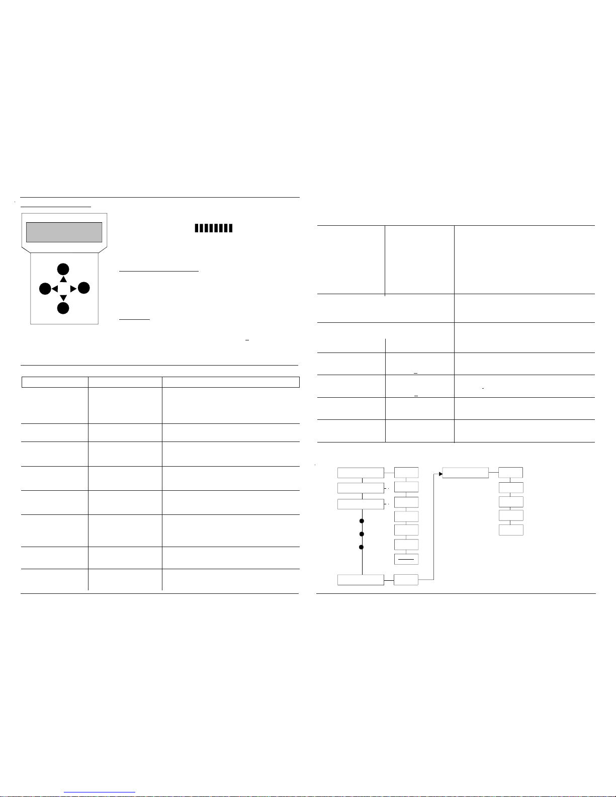
Handset an Buchse einstecken.
Betriebsspannung anschließen.
Display zeigt Information: WISI OM Startup.
Ein zunehmender Balken zeigt den Initialisierungsvorgang an.
Beliebige Taste drücken. „Search modules“mit rotierendem„\“ erscheint.
Display erscheinen die gefundenen Module z. B.:
1 OM 10 Ch 42
1 OM 10 Ch 44
Erklärung der Tastenfunktion
ST Tas ten — Bedienschritt wählen.
X Taste — Weiter zum Untermenü.
W Taste — Zurück zum Bedienschritt und mit Tasten
ST
nächsten Bedienschritt wählen.
Untermenü
WX T asten — Anzeige oder zu ändernden Wert wählen.
Cursor steht unter dem Wert
89
ST Tas ten — Wert ändern.
Handset OK... (Zubehör)
Parametereinstellung mit Handset
Left
Right
Down
Up
WISI OM V1.00
Mini Headend
Bedienschritte Display Einstellungen
Einzustellendes Beispiel Angezeigt sind 2 x Module OM 10 mit je 2 Ein-
Modul 1-6 wählen gängen.
Modul 1 1 OM 10 Ch 42 Eingang (A) – Ausgangskanal 42
1 OM 10 Ch 44 Eingang (B) – Ausgangskanal 44
Modul 2 2 OM 10 Ch 46 Eingang (A) – Ausgangskanal 46
2 OM 10 Ch 48 Eingang (B) – Ausgangskanal 48
Audioimpedanz AudImp Mit UP/DOWN-Taste wählen und mit R-
600 Ohm, 20 kOhm 600 Ohm Taste bestätigen.
Audiopegel AudLev Mit UP/DOWN-Taste wählen und mit R-
-6 dB...+ 6 dB 0 dB (3-dB-Schritte) Taste bestätigen.
Videopegel VidLev Mit UP/DOWN-Taste wählen und mit R-
-6 dB...+ 6 dB 0 dB (1-dB-Schritte) Taste bestätigen.
Testbild TstPic: off Mit UP/DOWN-Taste wählen.
off / sw off=kein Testbild
s/w=Balken mit 1-kHz-Signalton
TV-Standard
TV-Std: BG Ster Mit UP/DOWN-Taste wählen und mit R-
B/G*, D/K*, M, I, L Taste bestätigen. *B/G,* D/K in Stereo
Ausgangskanal/ Freq. OutFreq: Ch 42 Auswahl zwischen Frequenz- oder Kanal (siehe
ch 21-69 System-Einstellungen)
Legende: L/R-Taste =Left/Right
Handset
System-Einstellungen
System-Einstellungen 3 OM 10 Ch 52 Zu dieser Einstellung gelangt
man über die Menü-
wählen System settings Punkte Beispiel 3 x Module OM 10:
1 OM 10 Ch 42
1 OM 10 Ch 44
2 OM 10 Ch 46
2 OM 10 Ch 48
3 OM 10 Ch 50
3 OM 10 Ch 52
System settings mit den UP/DOWN-Tasten.
Bei OM 10, 11 nicht notwendig
LNB-Einstellung LNBSet System Mit UP/DOWN-Tasten auswählen.
wählen Ch/Frq settings
LNB-Spannung System Settings Mit UP/DOWN-Tasten auswählen.
14V 0kHz, 14V -22 kHz LNBSet: 14V 0kHz
18V 0kHz, 18V -22 kHz
Ausgangsfrequenz
System Settings Mit UP/DOWN-Tasten Kanal- oder Frequenz-
Channel / Freq. Ch/Frq: Channel anzeige auswählen.
Ausgangs-Attenuator
System Settings Cursor mit L/R-Taste auf Dezimalstelle
0...10 dB OutAtt: 3 schieben und mit UP/DOWN-Tasten einstellen.
Software-Version Sw-Ver Module1 Mit UP/DOWN-Tasten Modul wählen und mit R-
(nur Anzeige) Taste bestätigen.
Hardware-Version Hw-Ver Module1 Mit UP/DOWN-Tasten Modul wählen und mit R-
(nur Anzeige) Taste bestätigen.
Notwendige System-Einstellungen am Grundgerät OM 01 bei Erstinbetriebnahme
Modul 1
Modul 2
Modul 3
Modul 4
Modul 5
Modul 6
1 OM 10 Ch 42
1 OM 10 Ch 44
2 OM 10 Ch 46
2 OM 10 Ch 48
3 OM 10 Ch 50
3 OM 10 Ch 52
System-Settings
Audimp
AudLev
VidLev
TstPic
TV-Std
OutFreq
LNBSet
Ch/Frq
OutAtt
SW-Ver
HW-Ver
LNBSet
System-Settings
SW-Ver
HW-Ver
Haupt-Menü
ParameterMenü
Haupt-Menü
ParameterMenü
Menü-Struktur
 Loading...