

Page 1
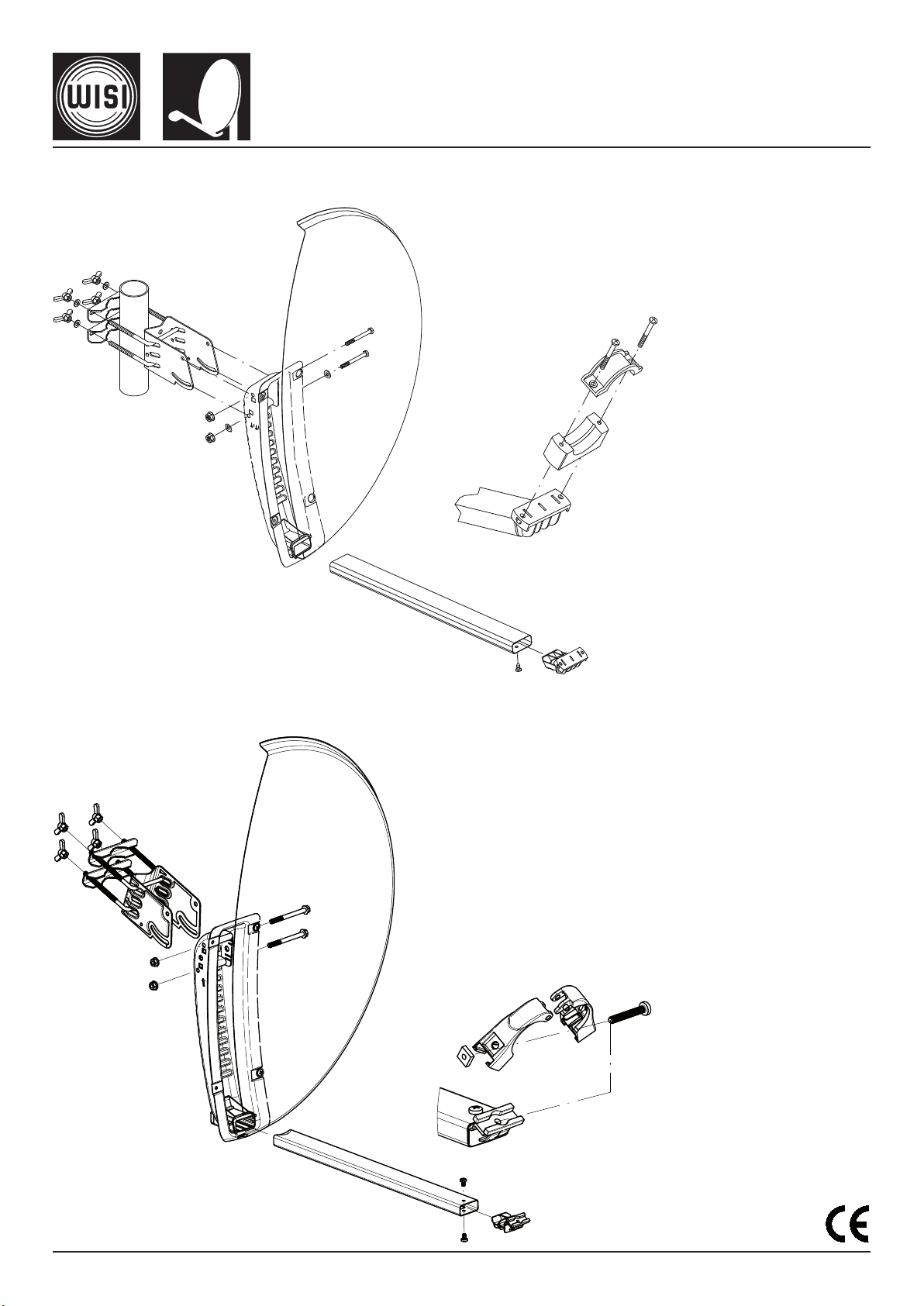
Montageanleitung
Mounting instructions
Instructions de montage
OA 36 WISI ORBIT Offsetantenne/Offset antenna/Antenne offset
OA 38 WISI ORBIT Offsetantenne/Offset antenna/Antenne offset
(D) (GB)
(F)
411 545
Page 2
- 2 -
Diese Informationen sind für Sie als Endkon su ment bestimmt. Bedie-
l
f
le
2m
1,5m
1 m
1 m
1 m
nung und Montage können unter Berücksichtigung der Aufstell- und
Gefahrenhin weise gefahrlos erfolgen. Sollten Sie dennoch Fragen
haben, steht Ihnen Ihr Fach händler bzw. Verkäufer zur Verfügung.
This information has been compiled for you as the end user. The
equipment will be safe to install and operate so long as you follow the
installation instructions and heed the warnings. If you should have any
further questions, your dealer or supplier will be pleased to assist.
Cette information a été recueillie à votre attention et à celle de
l'utilisateur final. L'équipement sera installé et fonctionnera en
toute sécurité pour autant que vous respectiez les instructions de
montage et que vous observiez les avertissements.
Pour toutes questions supplémentaires, veuillez vous adresser à
votre fournisseur o à votre distributeur qui se fera le plaisir de vous
aider.
(D) Aufstell- und Gefahrenhinweise
Standort bestimmen!
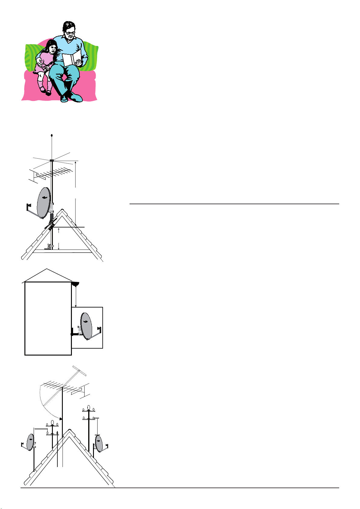
Wegen der auftretenden Windlast sollte die Antenne am Fußpunkt
einer Antennenanlage (siehe Abb.) montiert werden.
Bei einem Mastrohr ø von 40-76 mm beträgt die Mindest-Wandstärke 3,2 mm. Das Material besteht aus verzinktem Stahlrohr.
Wasser- und Gasrohre sind als Mastersatz unzulässig und
stellen eine potentielle Gefahr dar.
Einspannlänge: Der eingespannte Teil (l
stens ein sechstel der freien Länge (lf) betragen.
Verdrehen: Antennenmaste und alle Rohrverbindungen müssen
zuverlässig gegen Verdrehung gesichert sein.
Erdung: Die Antennenanlage muß nach EN 50 083 geerdet sein.
Von der Erdung ausgenommen sind:
Außenantennen, die mehr als 2 m unterhalb der Dachkante und
weniger als 1,5 m vom Gebäude angebracht sind (siehe Abb. ).
) des Mastes sollte wenig-
e
Hochspannung: Achten Sie darauf, daß Ihre Anlage von Starkstromfreileitungsnetzen den Mindestabstand einhält.
***
Page 3

- 3 -
(GB) Installation instructions and warnings
Select the installation location!
Due to the wind forces which may occur, the antenna is best installed
at the base of an aerial mast, since this usually still provides a clear
line of sight to the satellite. The mast should have a diameter of 4076 mm, with a minimum material thickness of 3.2 mm, and should
be made of galvanized steel tube.
Water or gas pipes are naot suitable materials for aerial masts
and may result in injury.
Clamped length the clamped length of the mast (l
) should be at
e
least one sixth of the free length (lf).
Twisting: aerial masts and all pipe connections must be secured to
prevent twisting.
Grounding: your aerial system must be correctly grounded. Consult
an electrician or your dealer for advice.
The following do not need to be grounded:
aerial systems which are at least 2m below the upper edge of the
roof and less than 1.5m away from the building (see fig.)
High voltages: take care that your aerial system is sufficiently far
away from overhead high-voltages lines.
***
(F) Dangers et consignes d'installation
Déterminer l'emplacement du montage!
Du fait de la force du vent, le antenne doit être montée sur le pied
d'une antenne qui présente également une vue dégagée vers le satellite.
Il est interdit d'utiliser les tuyaux d'eau et de gaz comme substitute du mât car ils représentent un danger potentiel.
Longueur de haubanage La partie de haubanée (l
une longueur minimale de un sixième de la longueur libre (l
) du mât doit avoir
e
).
f
Rotation:Le mât de l'antenne et tous les raccords tubulaires doivent
être parfeitement bloqués contre toute rotation.
Mise à la terre: Votre antenne doit être mise à la terre de façon
conforme. Faites appel à un professionnel.
Ne nécessitent pas de mise à la terre:
Les mâts d'antenne qui sont montés à plus de 2m sous la gouttière
et à moins de 1,5 du bâtiment (voir fig.)
Haute tension: Veillez à ce que votre installation respecte la distance minimale par rapport au réseau des lignes aériennes haute
tension voir fig.)
Page 4
- 4 -
Allgemeine Hinweise
7
10
Süden
South
Sud
Elevation
Süden
South
Sud
Azimut
OST
EAST
EST
ASTRA
1A-1E
Süden
South
Sud
EUTELSAT II-F1
+ Hot Bird 1
WEST
WEST
OUEST
Reflektorfläche
Schatten
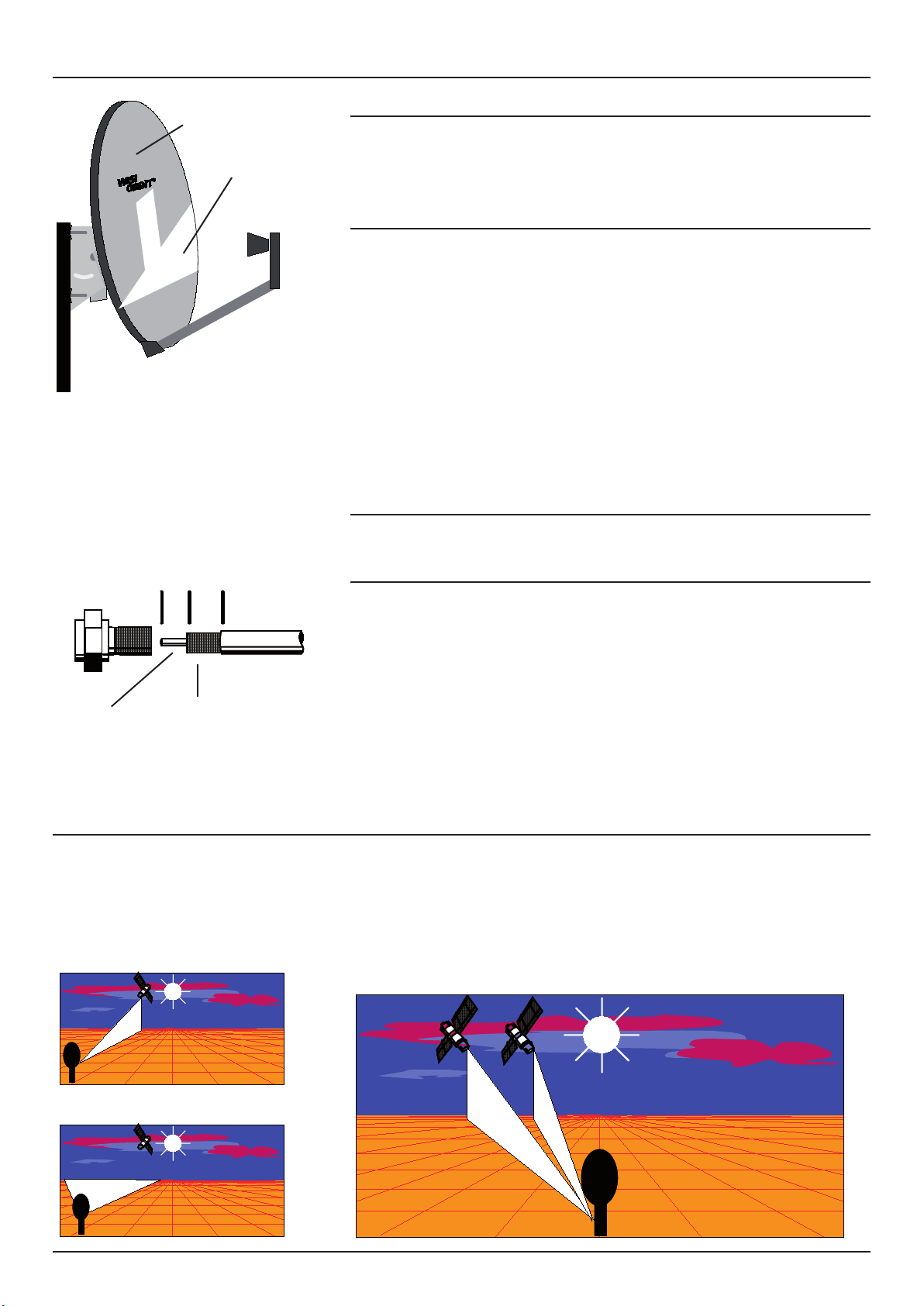
Bei der Montage vorkommende Fehler
1. Montageort abgeschattet
2. Falsches Antennenkabel
3. Kurzschluß, da Stecker falsch montiert.
Montageort sorgfältig auswählen
Empfangsqualität beeinträchtigt.
Der Montageort muß auch auf freie Sicht zum Satelliten ausgewählt werden. Abschattungen durch Gebäude, Bäume, Sträucher, Balkondecken und vorstehende Dachkanten beeinträchtigen den Empfang enorm.
Tip zur Abschattung: Eine Abschattung liegt dann vor, wenn
Sie am Montageort bei Sonnenlicht zwischen 12-13 Uhr Ihre
Anlage ausgerichtet haben und sich in der Reflektorfläche ein
Schatten zeigt. Sie müssen dann einen anderen Montageort auswählen.
Antennenkabel
Verwenden Sie ein hochwertiges Kabel aus der WISI MK-Serie.
mm
DV...
Kupferdraht
blank
Abschirmung
Anlage einstellen
MK...
PVC
Antennenkabel MK... und F-Stecker DV...korrekt montieren
Kabel abisolieren.
Achten Sie darauf, daß die Abschirmung (in der Zeichnung mit
10 gekennzeichnet) mit dem Innenleiter (in der Zeichnung mit 7
gekennzeichnet) keinen Kurzschluß bilden.
Stecker DV... auf das abisolierte Koaxialkabel MK... aufschrauben.
Wo finde ich ASTRA oder EUTELSAT?
Die Sonne steht mittags (annähernd 12-13 Uhr) im Süden (0°).
Die beiden Satelliten befinden sich links der Sonne (siehe Abb.).
(D)
Page 5
- 5 -
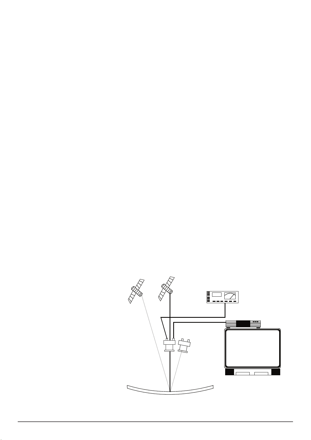
Benötigte Geräte: SAT-Receiver z. B. OR... und TV-Gerät oder
ASTRA 19,2° HOTBIRD 13°
1744
OR...
TV
selektives Meßgerät WA ... (Zubehör).
Visuelle Einstellung mit TV-Gerät und SAT-Receiver
1. Stellen Sie über SCART-Kabel die Verbindung Fernseher zum Sa-
tellitenreceiver her.
2. Drücken Sie die AV-Taste Ihrer Fernsehfernbedienung
3. Wählen Sie an Ihrem Satellitenreceiver den Pro gramm platz für ein
TV-Programm (z.B. ARD).
4. Schließen Sie den SAT-Receiver an den LNC-Anschluß
(Quadro = LH ) an.
5. Drehen Sie nun die Antenne auf den Satelliten und stellen die
Elevation (Neigung) und den Azimut (Drehen) ein, bis das TVProgramm an Ihrem TV-Gerät erscheint. Eine Elevationsskala am
Halter erleichtert die Einstellung.
Ist der Bildeindruck gut: alle Schrauben festziehen.
Einstellung mit Meßgerät WA ...
ARD wird auf 11.494 GHz gesendet. LO = 9.75 GHz.,
ZF = 1744 MHz.
1. Am WA ... stellen Sie 1744 MHz ein und schließen es an den LNCAnschluß (Quadro = LH) an.
2. LNC-Betriebsspannung am Meßinstrument einschalten und Antenne ausrichten, bis WA ... das Maximum
anzeigt.
Polarisationsentkopplung einstellen.
Bei leicht gelockerter Halteschelle den LNC gering verdrehen, bis ein
optimales Bild (Maximum am WA ...) erreicht wird.
(D)
Page 6
- 6 -
OST
EAST
EST
ASTRA
1A-1E
Süden
South
Sud
EUTELSAT II-F1
+ Hot Bird 1
WEST
WEST
OUEST
7
10
General information
Süden
South
Sud
Elevation
Süden
South
Sud
Azimut
Reflektor
obstacle
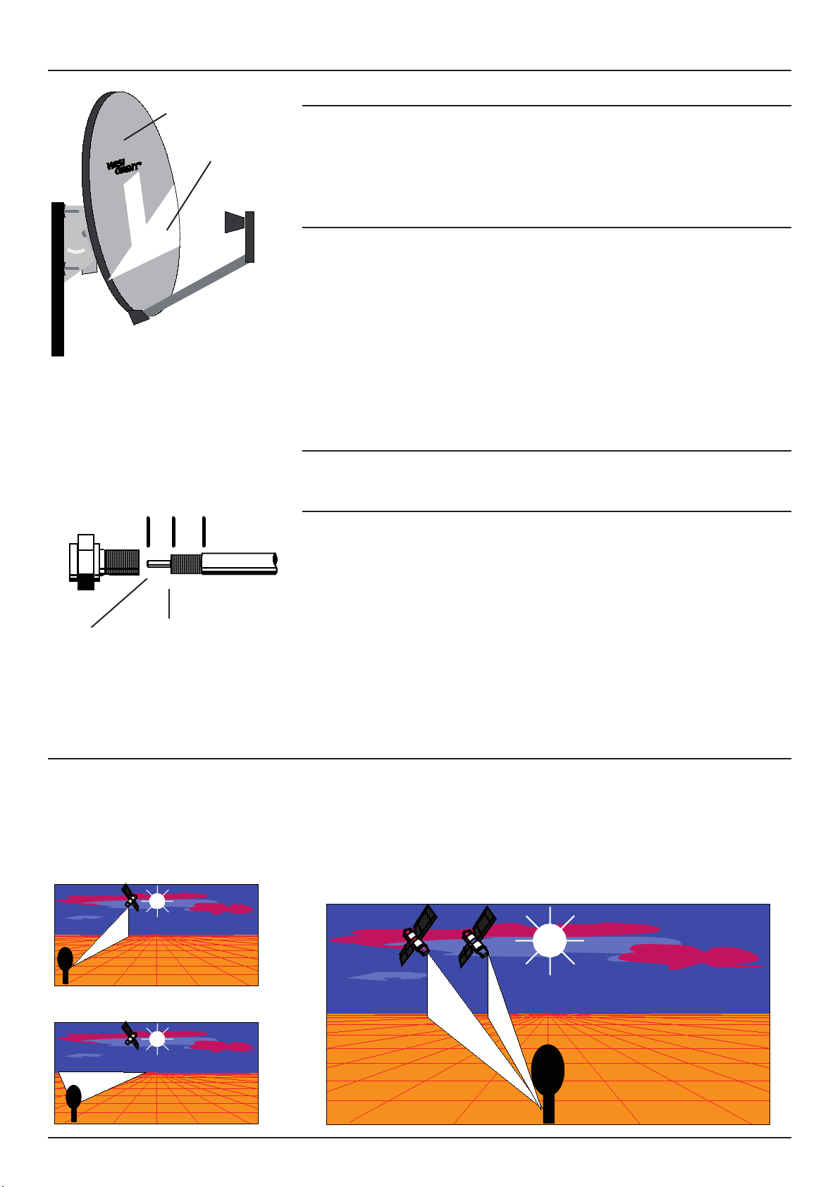
Incorrect mounting
1. Receiving location does not has free line of sight to the
satellite location. Obstractionn affect the receiption.
2. Used coaxial cable is not suitable for sat signal distribution.
3. Short circuit F-type plug is incorrect mounted.
Select the installation location carefully
Poor reception quality.
The installation location must ensure a free line of sight to the
satellite. Obstacles such as trees, buildings, bushes etc. between the
aerial and the satellite result in very bad reception.
How to check for obstacles: if, after installation and alignment,
sunlight casts a shadow on the reflector (at 1200 hours to 1300 hours)
this shadow is caused by obstacle which will impair reception. Select
a different installation location.
Antenna cable
Use low loss antenna cable from WISI a. ex. MK ...
mm
DV...
MK...
PVC
Cu-core
bare
Screening
Adjust the outdoor unit
Screw on plug DV... on the antenna cable MK... correctly
Stripe with a knife. Make sure that the screening (area 10 in the
drawing) does not produce a short circuit with the inner conductor
(aera 7 in the drawing),
Screw on F-type plug DV... onto stripped antenna cable MK...
Where do I find ASTRA and EUTELSAT?
The sun is in the South (0°) at 12hours to 13 hours. The two
satellites are to the left of the sun.
(GB)
Page 7
- 7 -
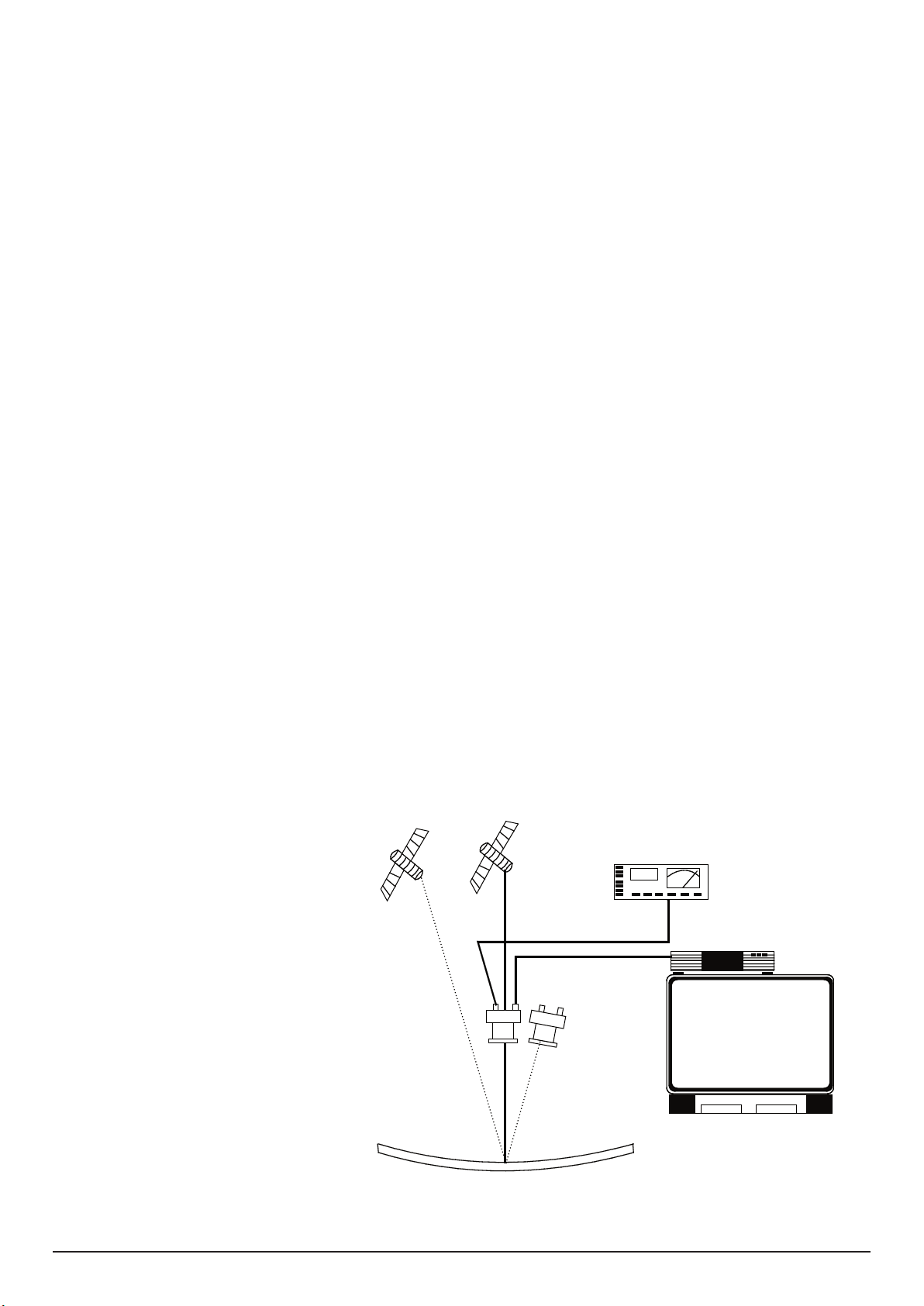
Equipment required: Sat Receiver OR... and TV set or selective measu-
ASTRA 19,2° HOTBIRD 13°
1744
OR...
TV
ring device WA ... .
Visual adjustment via TV set and SAT-Receiver
1. Connect the TV set to the satellite receiver with the SCART
cable.
2. Press the AV-button on your TV remote control.
3. Preselect the program place for your tv program (ARD) on your
satellite receiver..
4. Connect the SAT receiver to the LNC port (Quadro= LH)
5. Set the antenna to the satellite and adjust elevation and azimuth
(rotation). Check wether ARD appears on your TV set. Refer to the
elevation skale on the bracket.
Noisefree screen: Finally tighten all screws.
Adjustment with measuring device WA ...
ARD transponder at 11.494 GHz. LO = 9.75 GHz,
IF = 1744 MHz.
1.Set 1744 MHz on your WA ... and connect to the LNC port (Quadro = LH).
2.Switch on the operating voltage at WA ... and set to maximum
on WA ... .
Polarization decoupling.
Loosen the screws and turn the feed slightly until noisefree screen
(maximum at WA ... is achieved).
(GB)
Page 8
- 8 -
Information general
7
10
OST
EAST
EST
ASTRA
1A-1E
Süden
South
Sud
EUTELSAT II-F1
+ Hot Bird 1
WEST
WEST
OUEST
Süden
South
Sud
Elevation
Süden
South
Sud
Azimut
Reflecteur
obstacle
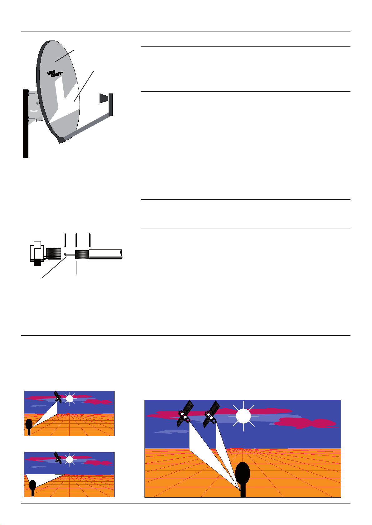
Erreurs pouvant être commises lors du montage
1. Lieu de montage en zone d'obstacle.
2. Câble d'antennes non adéquat.
3. Court-circuit, la fiche est mal montée.
Déterminer l'emplacement du montage
Le qualité de réception est mauvaise.
L'emplacement de montage doit être choisi de façon à affrir une
vue dégagée vers le satellite. Les obstacles tels que les arbres, les
buissons, les dalles en béton et les gouttières réduisent considérablement la qualité de l'image.
Comment savoir su la vue est bien dégagée: La vue est génée
si, après avoir aligné votre installation, vous pouvez constater une
ombre sur la surface du réflecteur à midi (à 13 heures, heure d'hiver).
Vous devez alors choisir un emplacement de montage différent.
Câble antenne
Utiliser le câble antenne de WISI MK ....
mm
DV...
MK...
PVC
Cu-core
bare
Screening
Ajustage le systéme
Montage de câble antenne MK.... et de Fiche F DV...
Veiller à ce que le blindage (10 sur le dessin) ne forme aucun courtcircuit avec le conducteur intérieur (7 sur le dessin)
Visser le connecteur DV... sur le câble coaxial MK... préalablement dénudé.
Où puis-je trouver ASTRA et EUTELSAT?
A midi (12.00 en heure ... 13.00 en heure d), le soleil est au sud (0°).
Les deus satellites se trouvent à gauche du soleil (voir fig.).
(F)
Page 9
- 9 -
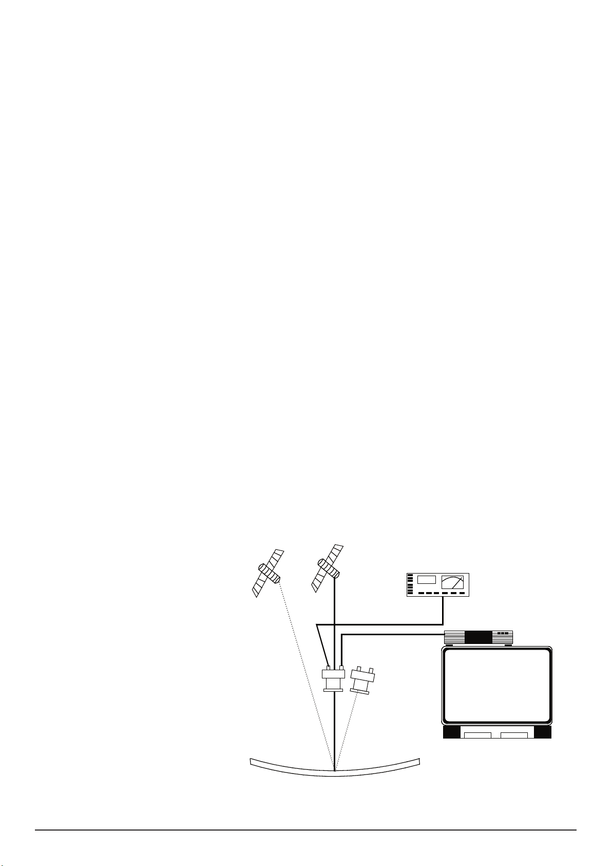
Appareils nécessaires: démodulateur Sat, par ex. OR 49 et téléviseur,
ASTRA 19,2° HOTBIRD 13°
1744
OR...
TV
ou mesureur sélectif WA ... .
Réglage visuel par démodulateur Sat
1. Réalisez la liaison entre téléviseur et démodulateur SAT, par
cordon Péritel.
2. Appuyez sur la touche AV de votre télécommande.
3. Sélectionnez sur votre démodulateur le numéro d'emplacement
du programme ARD.
4. Raccordez le démodulateur Sat à la sortie du LNC (Quadro = LH).
5. Tournez la parabole vers le satellite, et réglez l'elevation
(inclinaison) et l'azimut (rotation) jusqu'à ce que ARD apparaisse
sur votre téléviseur.
Voir marque de elevation.
Réglage avec le mesureur WA ...
ARD émet sur la fréquence11.494 GHz. O.L. = 9.75 GHz,
FI = 1744 MHz.
1. Réglez la WA ... sur 1744 MHz et reliez le à la sortie du LNC (Quadro = LH).
2. Brancher la tension de commande du LNC sur le mesureur, et régler
la parabole jusqu'à ce que l'aiguille du WA ... soit au maximum.
Serrer définitivement toutes les vis et remettre le capot.
Découplage de la polarisation
Uniquement en cas d'échange du LNC: régler le . Si le LNC est un peu
trop serré, le tourner légèrement, jusqu'à obtenir une image optimale
(aiguille du WA ... au maximum).
(F)
Page 10
- 10 -
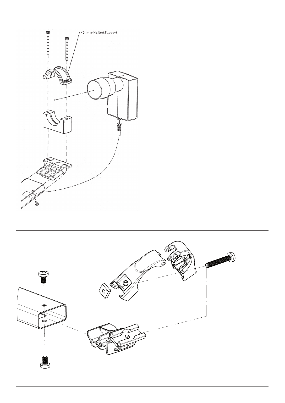
LNB Montage/mounting/montage OA 36
F-Anschluß abdichten!
Seal F connector !
Connection F (calfeutrer) !
LNB Montage/mounting/montage OA 38
Page 11
- 11 -
Cod.95090047
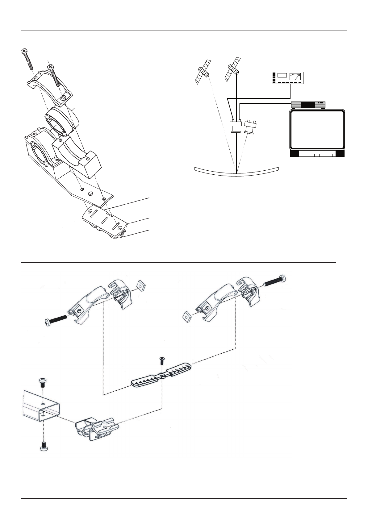
Duo-Feed für/for/pour OA 36 (optional/optionnel)
ASTRA 19,2° HOTBIRD 13°
1744
OR...
TV
ø 23 / 40 mm
OP 08 C Duo-Feedhalterung für 2 LNBs
OP 08 C Duo-Feed bracket for 2 feed systems
OP 08 C Fixation double pour 2 têtes SHF
Multi-Feed für/for/pour OA 38 (optional/optionnel)
OF 85 0002 Multifeedschiene für 2 LNBs,
inkl. Feedhalter
OF 85 0002 Multifeed bracket for 2 feed systems,
incl. feed holders
OF 85 0002 Fixation quatruple pour 2 têtes SHF,
braf pour LNB inclus
OF 85 0004 Multifeedschiene für 4 LNBs,
inkl. Feedhalter
OF 85 0004 Multifeed bracket for 4 feed systems,
incl. feed holders
OF 85 0004 Fixation quatruple pour 4 têtes SHF,
braf pour LNB inclus
Page 12
Technische Daten - Specifications - Caractéristiques techniques
Offsetantennen
Offset antennas
Antenne offset
OA 36 OA 38
60 cm 80 cm
Reflektor Aluminium Aluminium
3-dB-Öffnungswinkel 3,0° 2,5°
Gewinn 34,6 dB 34,6 dB
Einstellbereich Elevation 16-50° 16-50°
Windlast bis 20m Montagehöhe 280 N 525 N
Gewicht 1,6 kg 3,8 kg
Reflector Aluminium Aluminium
3dB aperture angle 3,0° 2,5°
Gain 34,6 dB 34,6 dB
Setting range, elevation 16-50° 16-50°
Windload up to 20m mounting height 280 N 525 N
Weight 1,6 kg 3,8 kg
Réflecteur Aluminium Aluminium
Angle d'ouverture 3 dB 3,0° 2,5°
Gain 34,6 dB 34,6 dB
Amplitude du réglage d'élévation 16-50° 16-50°
Charge au vent jusqu'à 20m de hauteur 280 N 525 N
Poids 1,6 kg 3,8 kg
WISI Communications GmbH & Co. KG
Empfangs- und Verteiltechnik
Wilhelm-Sihn-Straße 5-7, 75223 Niefern-Öschelbronn
Tel . 07233 / 66-292, Fax. 66-320, http://www.wisi.de
excellence in digital ...
Technische Änderungen und Druckfehler vorbehalten!
Technical Modifications reserved. WISI cannot be held
liable for any printing error.
Sous réserve de modifications techniques et d‘erreurs
d‘impressions.
02/10
 Loading...