

Page 1
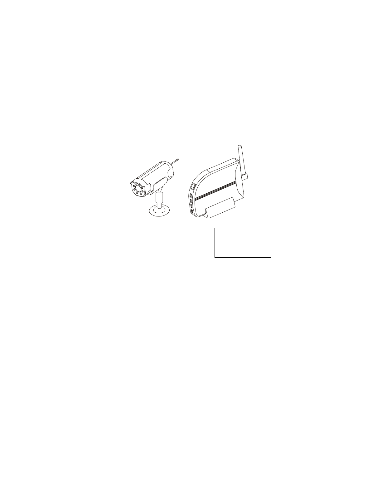
USER’S
INSTRUCTIONS
2.4 GHz WIRELESS
COLOR CAMERA SYSTEM
PORTABLE WIRELESS
COLOR CAMERA & RECEIVER
MODEL CW3510
WISECOMM
LOGO
Page 2

IMPORTANT SAFETY PRECAUTIONS
■ To prevent fire or shock hazard, do not expose this product to
rain or moisture.
■ To avoid electrical shock, do not open the case of this product.
■ Operate this product using only the power supply included.
■ Do not overload electrical outlets or extension cords, this can
result in fire or electric shock.
■ Keep this product away from the microwave oven, near high
voltage and high temperature area, otherwise the battery inside
the camera may cause explosion or fire.
■ Do not expose this product in direct sunlight or strong reflected
rays.
■ Refer servicing to qualified personnel only.
■ Do not change or modify this product, the warranty terms will
be voided.
NOTE
This equipment has been tested and found to comply with the limits for
Class B digital device, pursuant to part 15 of the FCC rules. These
limits are designed to provide reasonable protection against harmful
interference in a residential installation.
This equipment generates, uses and can radiate radio frequency energy
and, if not installed and used in accordance with the instructions, may
cause harmful interference to radio communications.
Page 3

However, there is no guarantee that interference will not occur in a
particular installation. If this equipment does cause harmful
interference to radio or television reception, which can be determined
by turning the equipment off and on, the user is encouraged to try to
correct the interference by one or more of the following measures:
■ Reorient or relocate the receiving antenna.
■ Increase the separation between the equipment and receiver.
■ Connect the equipment into an outlet on a circuit different
from that to which the receiver is connected.
■ Consult the dealer or an experienced radio/TV technician for help.
HOW TO USE CW3510 FOR OPTIMAL PERFORMANCE
1 CW3510 should be placed on a flat, stable surface to prevent
damage to it from falling.
2 For maximum operating range, try to minimize the number of
obstacles (TV, other electronics, large steel structures) between the
transmitter and the receiver units.
3. Avoid pointing the camera directly into light or extreme sunlight.
This will interfere with your ability to obtain a proper image
4. To receive optimum image performance, always make sure lenses
are kept clean.
5. This camera is not waterproof. Do not use in wet or high humidity
environments, as this can cause damage or electrical
shock.
Page 4
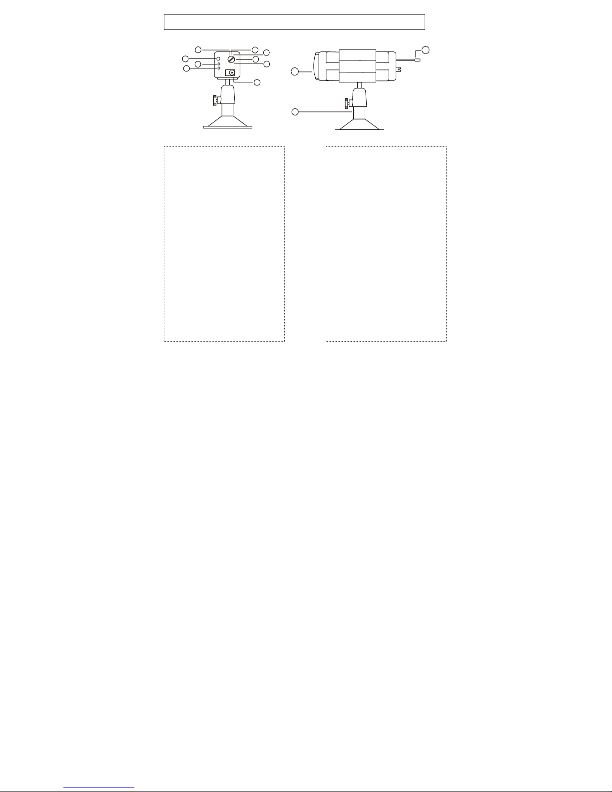
WIRLESS CAMERA
-------CW3510TX
6
4
3
1
5
9
7
8
2
1.CHARGE LED (RED)
Indicates that the built-in
battery is being charged.
2.POWER JACK (DC 5V)
Plug the 5V adapter
(supplied).
3.POWER ON LED
(GREEN)
Indicates that the power is
ON or OFF.
4.ANTENNA
Sends audio and video
signals.
5.POWER OFF
When the switch is at this
position, the power is off.
6-9. CHANNEL SELECTION KNOB
Must select the same channel on both
transmitter and receiver.
12
10
11
10.IR LED
Help work at night and dark
Place.
11.Universal mounting bracket
Make the camera to work at
any .direction.
12. Antenna
Sends audio and video
signals.
Page 5
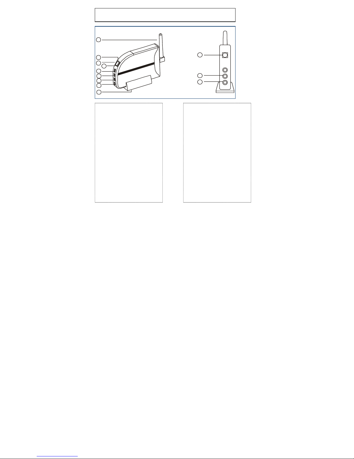
WIRELESS RECEIVER---CW3510RX
1
2
3
4
5
6
7
8
9
1.ANTE NNA
Receives the audio and video
signals.
2. POWER INDICATOR
The red LED is lit when
the power is on.
3.CHANNEL SELECTION BUTTON
Use to find optimal reception. Must select
the same channel on both transmitter and
receiver.
4.AUTO SWITCHING
INDICATOR
The yellow LED is lit when in the
sequencing mode.
5.CH 1
This light is lit when CH1 has been selected
6.CH 2
This light is lit when CH2 has been selected
10
11
12
7.CH 3
This light is lit when CH3 has been selected.
8.CH 4
This light is lit when CH4 has been selected.
9. BRACKET
For the receiver to stand
10.POWER ON/OFF SWITCH
Switch for the power On/off.
11.DC IN
Plug the 8V adapter (Supplied).
12.AV (AUDIO/VIDEO) OUTPUT JACK
Connect the supplied A/V cable to the jack.
Plug the yellow colored RCA to the VIDEO
IN on the monitor/TV and the white colored
RCA to the AUDIO IN respectively.
Page 6
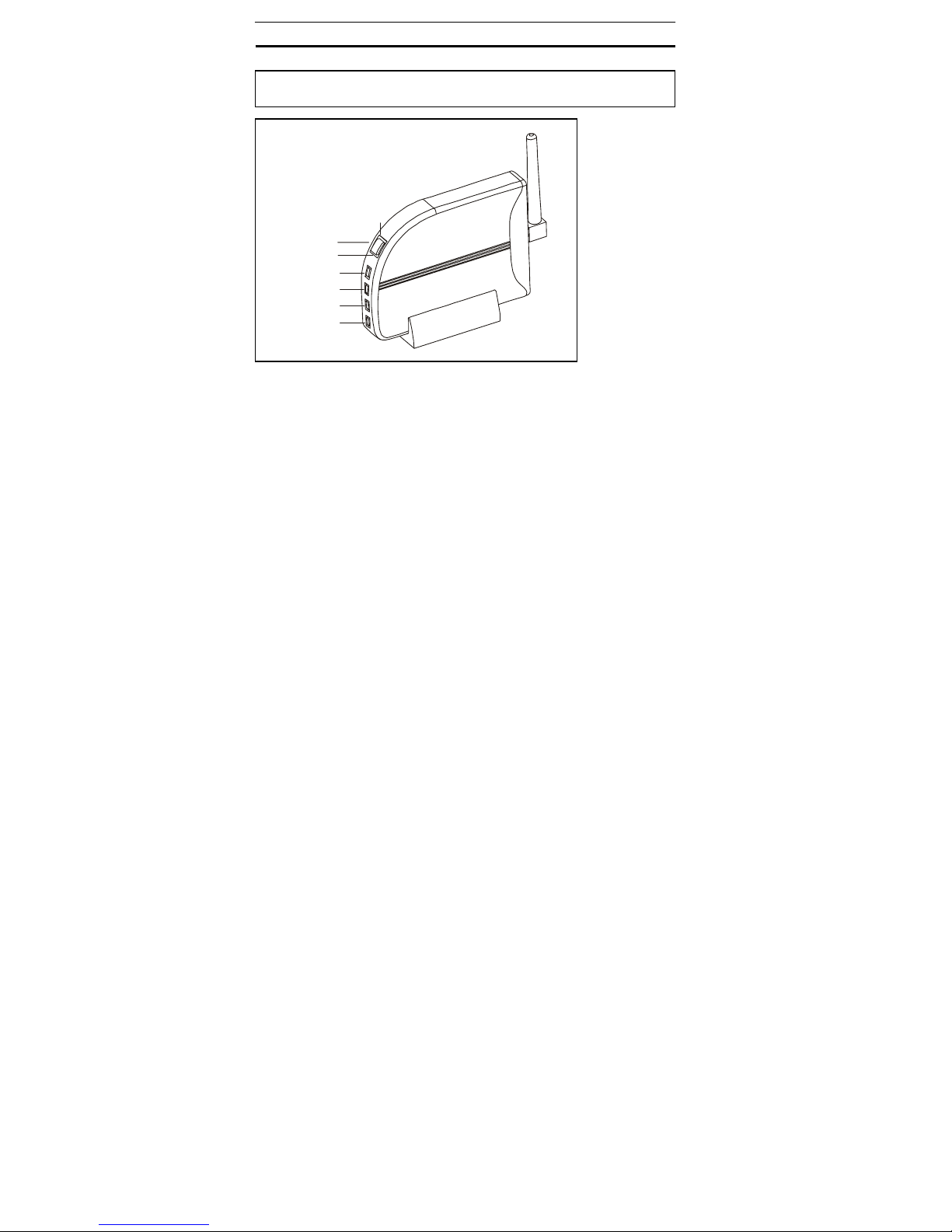
INSTALLATION
WIRELESS CAMERA---CW3510TX
AUTO SWITCHING
Change the picture above from RX to TX(camera)
1. Connect the supplied adaptor (DC 5V 700mA) to the DC IN jack on
POWER INDICATOR
SEL
INDICATOR
CH1
CH2
CH3
CH4
the rear of the camera and plug it into AC power outlet. The red LED
(power indicator light) on the back of the camera will be lit and the
battery (inside the camera) will be charging (green LED).
2. Charge the battery first for 2 hours prior to use.
3. Select the channel you wish to view.
Page 7
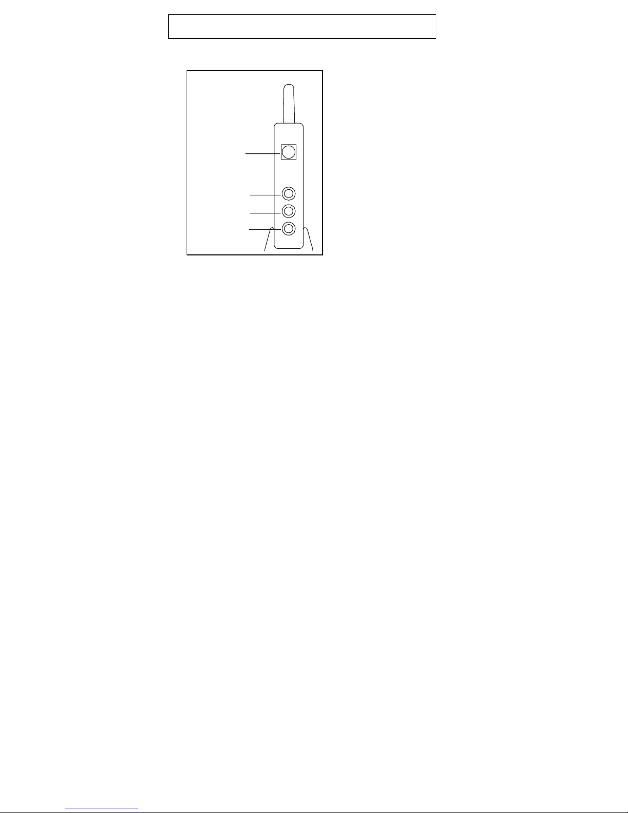
WIRELESS RECEIVER---CW3510RX
POWER ON/OFF
ANTENNA
DC IN
AV O U T
1.
Connect the supplied AC adaptor (DC 8V 200 mA to the DC IN jack
of the receiver and plug it into AC outlet.
2. Connect the supplied A/V cable to the jack. Plug the yellow colored
RCA to the VIDEO IN on the monitor/TV and the white colored
RCA to the AUDIO IN respectively.
3. Turn on the power switch.
4. Press the SEL button to select the same channel as the camera.
Page 8

OPERATION
■ MANUAL MODE
Select the same channel with the SEL button on receiver as the
channel of camera.
■
AUTOMATIC MODE
Press SEL button on the receiver after CH 4 indicator is lit. It will
be in the sequencing mode. Please check the explanation.
■ OPERATION WITH TV /MONITOR
1. If your color TV/MONITOR has A/V jacks, connect the
supplied A/V cable to TV’s A/V jacks and to the A/V jack on
the receiver. Be sure to connect the white connector of the
A/V cable to the AUDIO IN jack and the yellow connector of the
A/V cable to the VIDEO IN jack on the TV or MONITOR.
2. Plug the provided AC adapter (DC 8V 200mA) into the DC
jack on the receiver and the other end into AC outlet.
Make sure the POWER switch is in the OFF position beforehand.
3.Locate and orient the receiver to get optimal performance.
4.Be sure the TV/monitor and the receiver are turned on.
REDRAW THE PICTURE
TV/MONITOR
Page 9
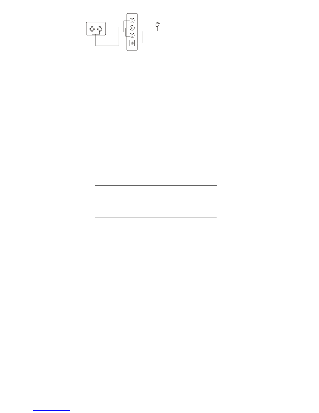
A
AUDIO VI DEO
INPUT
/V CABLE
VIDEO
OUT
AUDIO
DC
TO POWER
OUTLET
L
R
■ OPERATION WITH TV/MONITOR AND VCR
1.Connect the provided A/V (audio/video) cable to the A/V jack
on the receiver and to the jacks on your VCR’s A/V jacks.
Be sure to connect the white connector of the A/V cable to the
AUDIO IN jack and the yellow connector of the A/V cable to the
VIDEO IN jack on the VCR, if the VCR has only a single jack for
video input, connect the yellow plug to it.
2.Connect the other A/V cable (not supplied) to the VIDEO OUT
and AUDIO OUT jacks on your VCR. Connect the other ends to
VIDEO IN and AUDIO IN jacks on your TV/monitor.
3. Plug the provided AC adapter (DC 8V 200mA) into the DC
jack on the receiver and the other end into AC outlet.
Make sure the POWER switch is in the OFF position beforehand.
4.Locate and orient the receiver to get optimal performance.
5.Be sure the TV/monitor and the receiver are turned on.
▪ Each VCR manufacturer uses different recording
method. Refer to VCR’s instructions if it is
impossible to setup the menu.
Page 10
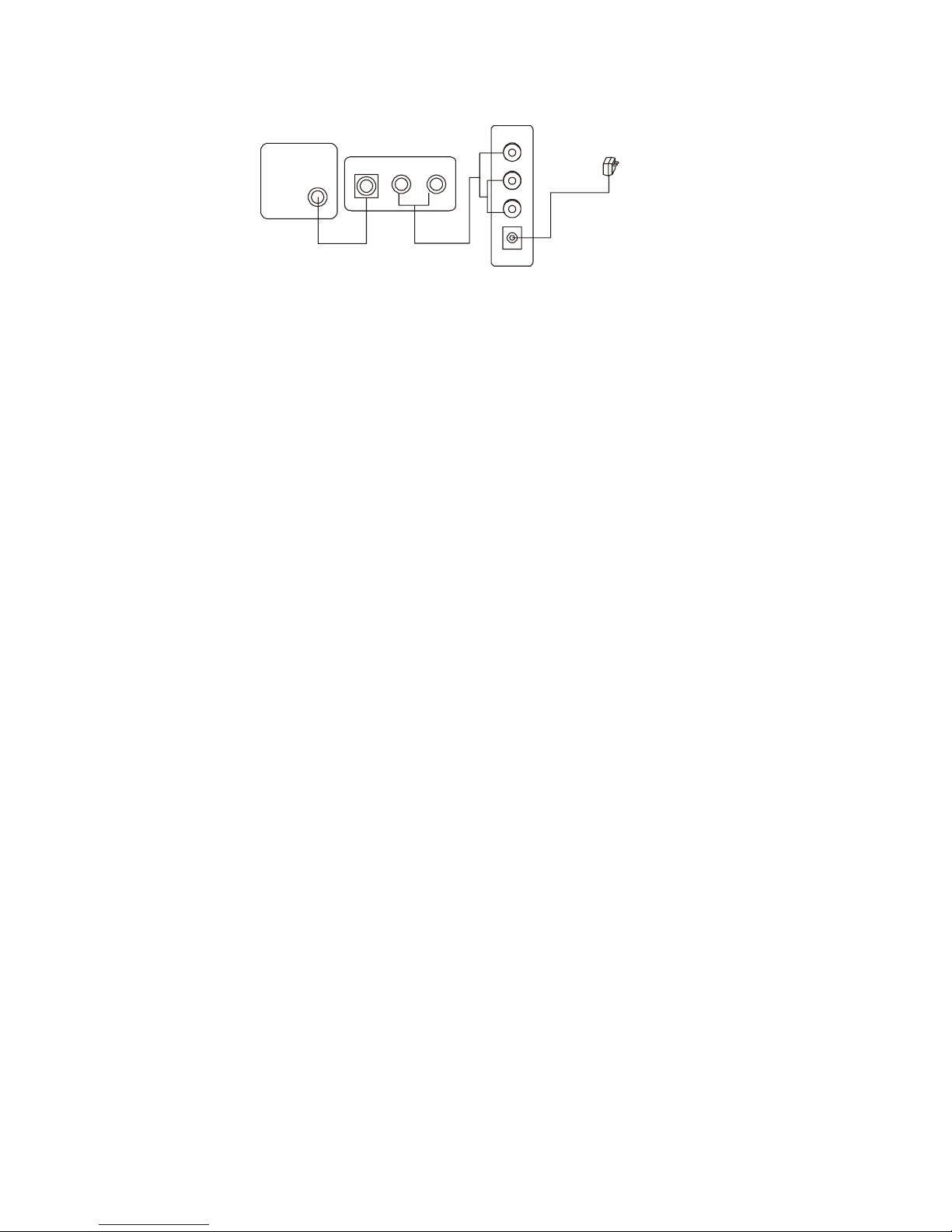
REDRAW THE PICTURE
TV VCR
AUDIO VI DEO
OUT
INPUT
COAXIAL CABLE
A/V CABLE
RECEIVER
SIDE PANEL
VIDEO
L
OUT
AUDIO
R
DC
TO POW ER
OUTLET
Page 11
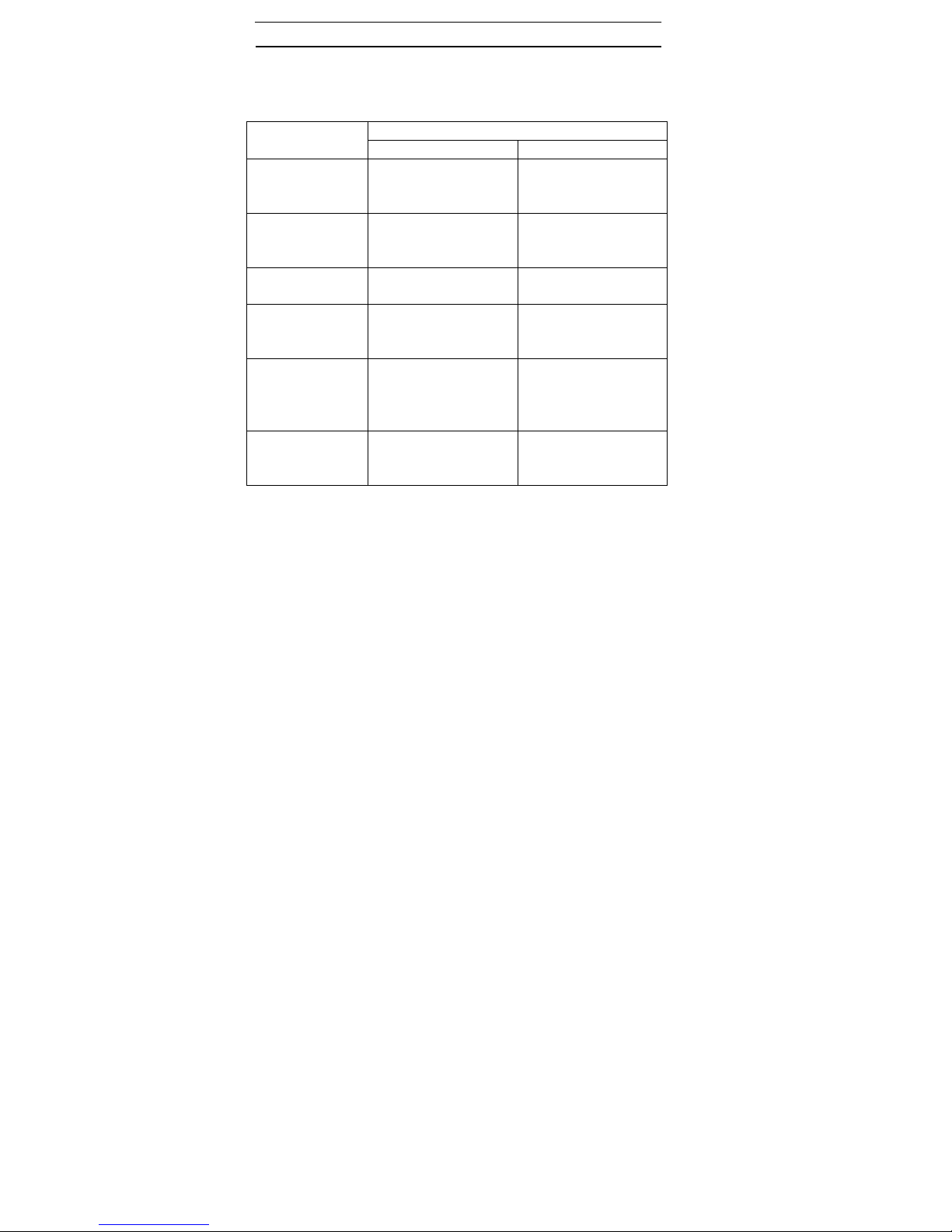
TROUBLE SHOOTING
789
If the system does not function properly, check the following
points before contacting the service center.
Problems
No power(no
picture/sound)
Poor reception
Picture flicking
Dim picture,
picture too
bright, too dark
Picture rolls and
Jumps.
scrambled
picture
Picture smaller
than screen or
volume weak
Receiver Camera
AC adaptor was not
plugged into the
outlet properly.
Improper antenna
direction. Improper
channel setting
------ Strong spotlight in
Improper brightness
control setting on
your TV/Monitor
Improper V-hold
control setting on
your TV/Monitor
House current may
be too low
Cause and remedies
AC adaptor was not
plugged into the
outlet properly.
Check the distance
and blocks.
the field of view
Lighting source in
The field of view
-----
House current may
be too low
1.CHARGE LED (RED)
Indicates that the built-in
battery is being charged.
2.POWER JACK (DC 5V)
Plug the 5V adapter
(supplied).
3.POWER ON LED
(GREEN)
Indicates that the power is
working or not.
4.ANTENNA
Page 12

SPECIFICATIONSS
WIRELESS RECEIVER
Receiving frequency 4CH 2,400 to 2,483MHz
Demodulation FM
Antenna 50 ohm SMA
Receiving sensitivity -85dbm
Video output 1VP-P @75 ohm
Audio output 1VP-P @600 ohm
Power supply DC 8V
Current consumption 180 mA
Lithium battery 500 mAH
Dimensions ???????
Weight ????????
WIRELESS CAMERA
Output level 90db microvolts/meter @3 meter
Operating frequency band 4CH 2,400 to 2,483MHZ
Modulation FM
Video input level 1.0VP-P @75 ohm
Audio input level 1.0VP-P @600 ohm
Image sensor 1/3” C-MOS sensor
Page 13

Number of pixels NTSC, 510 x 492
Resolution 380 TV lines
Scanning system 525 lines, 60 fields/sec
Sync system Internal sync
Minimum illumination 1.5 Lux/F1.5 & IR LED on: 0 Lux
S/N ratio More than 45db
Gamma characteristics 0.45
Electronic shutter speed 1/60 to 1,500 sec
Lens 78º wide angle lens
Microphone Condenser
Lithium battery 500 mAH
Charging time 2 hour
Working time 5 hour
Operating temperature 14ºF to 122ºF
Dimensions ????????
Weight ????????
Specifications are subject to change without notice.
Basic System Includes
1- 2.4 GHz wireless receiver
1-2.4 GHz wireless camera
2-UL approved AC adapter
Page 14

1-A/V (audio/video) cable
1-User’s instruction
1-Warranty registration card
1-Camera bracket
1-Receiver bracket
LIMITED 1YEAR WARRANTY
This warranty gives the original purchaser specific legal rights and
may also have other rights, which vary from state to state. If our
products do not function because of any defect in material or
workmanship, we will repair free of charges for 1 year on parts and
labor from the date of original purchase. This warranty does not
cover modification, abuse, incidental or consequential damages
unless the state of owner’s residence specially prohibits limitations
on incidental or consequential damages.
HOW TO OBTAIN FACTORY SERVICE
1. Original purchaser must fill out a warranty card and mail it to
the factory with model number, serial number and the date of
purchase.
2. We will repair or replace, and return to the owner the system
under this limited warranty.
3. Please pack the system carefully and securely using the
original packing materials, and send it prepaid and insured to:
13073 E. 166
th
St. Cerritos, CA 90703
Page 15

4. Please include a check for $20.00 to cover the cost of return
postage and handling. If the system is returned within the
warranty period, please include a proof of purchase. If the
system is out of warranty, you will receive an estimate of the
repair cost for your approval before repair work will be started.
 Loading...