

Operating Instructions
Vacuum based lifting device
for prefabricated glass and cladding elements
OKTOPUS® GLASS-Jack
GL-RN 400/600/800
Serial no.: A 810 772
Technical documentation
BA 000 101
07/2016
The present technical documentation corresponds to the status as per the date of issue.
WIRTH GMBH
INSTALLATION SYSTEMS DIVISION
Brehnaer Straße 1
D-06188 Landsberg
Phone: +49 (0) 34 602 / 70 88 - 0
Fax +49 (0) 34 602 / 70 88 - 111
www.wirth-gmbh.com
Original instructions
Proprietary notice as per ISO 16016

O p e r a t i n g I n s t r u c t i o n s
OKTOPUS® GLASS-Jack
GL-RN 400/600/800
Technical Documentation
BA 000 101
Page 2 of 27
Page
Table of Contents 2
1 General information regarding the OKTOPUS® 4
1.1 Manufacturer’s information 4
1.2 Service workshop 4
1.3 Scope of application 4
2 Proper use of the OKTOPUS
®
5
2.1 Mode of operation and safety concept of the OKTOPUS
®
system 5
2.2 Safety instructions 6
2.3 Symbols and markings 7
2.4 Design and application of the OKTOPUS
®
8
2.5 Conditions and restrictions of application 11
2.6 Transport and storage 12
3 Instructions for use of the OKTOPUS® 13
3.1 Power supply 13
3.2 Vacuum supply 14
3.3 Control panel/switch 15
3.4 Start-up 15
3.5 Handling of glass and cladding elements 16
3.5.1 Handling of lying glass and cladding elements 16
3.5.2 Handling of glass and cladding elements standing upright 17
3.5.3 Rotating a load hanging in a vertical position with
the OKTOPUS
®
GLASS-Jack GL-RN 400/600/800 with a crane arm 18
3.5.4 Rotating a load hanging in a vertical position with
the OKTOPUS
®
GLASS-Jack GL-RN 400/600/800 with guide ring 18
3.5.5 Swivelling a load hanging in a vertical position with
the OKTOPUS
®
GLASS-Jack GL-RN 400/600/800 with crane arm 19
3.5.6 OKTOPUS
®
GLASS-Jack GL-RN 400/600/800 slung to the basic frame 20
3.6 Converting the OKTOPUS
®
into its different versions 20
3.6.1 Assembly of the guide ring 20
3.6.2 Mounting of the crane arm 21
3.6.3 Mounting of the extension arms (4 suction pads) 21
3.6.4 Mounting of the extension arms (6 resp. 8 suction pads) 22
4 Servicing and Maintenance 23
4.1 General 23
4.2 Mechanical components 23
4.3 Vacuum system 24
4.3.1 Cleaning the suction pads 24
4.4 Electrics and electrical components 25
5 Conduct in the event of hazardous incidents 27
6 Disposal and Recycling 27
Annex 1: Short summary of operating instructions
OKTOPUS
®
GLASS-Jack GL-RN 400/600/800
Annex 2: Functional dimensions
Annex 3: EC Declaration of conformity
Annex 4: Test badge pursuant to the directive 2006/42/EU
Annex 5: Electrical Circuit Diagram

O p e r a t i n g I n s t r u c t i o n s
OKTOPUS® GLASS-Jack
GL-RN 400/600/800
Technical Documentation
BA 000 101
Page 3 of 27
Page
Table of Figures
3
Fig. 1: OKTOPUS® GLASS-Jack GL-RN 400 with crane arm 8
Fig. 2: OKTOPUS
®
GLASS-Jack GL-RN 400 with crane arm and extensions 9
Fig. 3: OKTOPUS® GLASS-Jack GL-RN 600 with crane arm and extensions 9
Fig. 4: OKTOPUS
®
GLASS-Jack GL-RN 800 with crane arm and extensions 9
Fig. 5: OKTOPUS® GLASS-Jack GL-RN 400/600/800 with guide ring 9
Fig. 6: Load lifting attachment OKTOPUS® GLASS-Jack GL-RN 400/600/800 10
Fig. 7: Transport rack 12
Fig. 8: Charge indicator 13
Fig. 9: Vacuum gauge 14
Fig. 10: Control panel 15
Fig. 11: OKTOPUS
®
GLASS-Jack GL-RN 400 and 800 with glass element 17
Fig. 12: OKTOPUS
®
GLASS-Jack GL-RN 400/600/800 with guide ring resp. crane arm 18
Fig. 13: OKTOPUS® GLASS-Jack GL-RN 400/600/800 with guide ring, with crane arm,
and with crane arm and extension arms (6 or 8 suction pads respectively) 19
Fig. 14: OKTOPUS
®
GLASS-Jack GL-RN 800 during swivelling 19
Fig. 15: Guide ring mounting 20
Fig. 16: Mounting of the extensions (4 suction pads) 21
Fig. 17: Mounting of the extension arms (ex. 8 suction pads) 22
Fig. 18: Suction pad 24
Fig. 19: Battery charger (sample) 25
Fig. 20: Warning devices 27

O p e r a t i n g I n s t r u c t i o n s
OKTOPUS® GLASS-Jack
GL-RN 400/600/800
Technical Documentation
BA 000 101
Page 4 of 27
1 General information regarding the OKTOPUS®
1.1 Manufacturer’s information
Manufacturer’s name and registered office:
WIRTH GMBH
Installation Systems Division
Brehnaer Straße 1
D-06188 Landsberg
Germany
Device characteristics:
Product description: OKTOPUS
®
GLASS-Jack GL-RN 400/600/800
Type: OKTOPUS® GLASS-Jack GL-RN 400/600/800 R M B24 P 110
Serial number: (see type plate)
Year of manufacture: (see type plate)
Weight:
approx. 55 kg (basic unit, crane arm, 4 suction pads)
approx. 60 kg (basic unit, crane arm, 4 suction pads, 4 extensions)
approx. 70 kg (basic unit, crane arm, 6 suction pads, 4 extensions)
approx. 80 kg (basic unit, crane arm, 8 suction pads, 4 extensions)
approx. 60 kg (basic unit, guide ring, 4 suction pads)
Working Load Limit: max. 300 kg (guide ring, 4 suction pads ∅ 400 mm)
max. 400 kg (crane arm, 4 suction pads ∅ 400 mm)
max. 600 kg (crane arm, 6 suction pads ∅ 400 mm)
max. 800 kg (crane arm, 8 suction pads ∅ 400 mm)
CE mark: pursuant to EC Declaration of conformity Annex 3
Test badge as per Annex 4 on the unit.
1.2 Service workshop
WIRTH GMBH Telefon: +49 (0) 34 602 / 70 88 - 0
Brehnaer Str. 1 Fax-Nr.: +49 (0) 34 602 / 70 88 - 111
D-06188 Landsberg E-Mail:
info@wirth-gmbh.com
1.3 Scope of application
The operating instructions on hand represent the state-of-the-art and the safety measures defined by the European Machinery Directive valid at the editing date of the manual.
Diverging or amending national regulations may not be considered eventually.
The user is exclusively responsible to observe such regulations.

O p e r a t i n g I n s t r u c t i o n s
OKTOPUS® GLASS-Jack
GL-RN 400/600/800
Technical Documentation
BA 000 101
Page 5 of 27
2 Proper use of the OKTOPUS®
2.1 Mode of operation and safety concept of the OKTOPUS® system
The devices of the OKTOPUS® system are „Load lifting attachments“ following the principle
of a „Vacuum lifter“. They are installed to a hoist or work as a stand-alone unit, and are used
for handling and positioning large-size construction elements.
The basic functions of the OKTOPUS
®
system comprise:
⇒ Controlled suction and release of large-size construction elements having sufficient inherent
stability by use of one or more vacuum suction pads of the OKTOPUS
®
,
⇒ transport and positioning of the sucked construction elements by manipulating the OK-
TOPUS,
⇒ fine positioning of the construction elements using the control of the OKTOPUS
®
-axes (if
available).
The OKTOPUS
®
system is offered in various types of design and models for different fields of
application. These differ depending on the used hoist, the loads to be lifted, the necessary positioning movements and the used controls.
For further information please do not hesitate to contact us (
www.wirth-gmbh.com).
Specific safety requirements, which have been taken into account during construction, execution, technical documentation and in drawing up the operating instructions for the OKTOPUS
®
system, arise due to the special function of the OKTOPUS system as a “load lifting attachment”.
Therefore, strict compliance with the instructions and information for proper and safe use of the
device given in the operating instructions is a prerequisite for the manufacturer’s warranties during the agreed warranty period.
The OKTOPUS
®
user is responsible for combining the OKTOPUS® system to a hoist. The user
himself is responsible for proper implementation of the relevant guidelines and instructions. The
information provided by the manufacturer of the OKTOPUS
®
system through these operating in-
structions shall be considered as an additional support for the user.
Before initial start-up of the system, skilled staff shall check at the user’s premises, whether the
combination of OKTOPUS
®
system / crane or hoist is suitable for use.
Moreover, the OKTOPUS® shall be subject to tests by an expert at regular intervals (please refer to pt. 4.1). Experts are persons who have sufficient knowledge in the field of load lifting attachments on account of their education and experience in the concerned subject and who are
being highly acquainted with the relevant safety-at-work instructions and safety precautions,
guidelines and generally accepted engineering standards, so that they can evaluate the state of
the load lifting attachments as being safe for operation.
Initial testing of the crane or lifting device/OKTOPUS
®
combination as well as the successful
completion of the annual test of the OKTOPUS® system by an expert shall be documented.
The manufacturer of the OKTOPUS® system offers expert testing as a service and documents
testing of the OKTOPUS® by placing the test badge on the test card in accordance with Annex 4
together with the indication of the date for the next test.

O p e r a t i n g I n s t r u c t i o n s
OKTOPUS® GLASS-Jack
GL-RN 400/600/800
Technical Documentation
BA 000 101
Page 6 of 27
2.2 Safety instructions
(1) Only employ cranes with a Working Load Limit that exceeds the live weight of the
OKTOPUS® GLASS-Jack GL-RN 400/600/800 in all working positions by at least 90 kg!
(2) Never use a damaged, not fully functioning or incomplete OKTOPUS
®
!
(3) Have your combination crane/OKTOPUS
®
tested and documented by an expert prior to
initial start-up!
(4) Operate the crane with an operating license only!
(5) Only operate the OKTOPUS
®
and the crane, if you are familiar with the operating and
display elements as well as with the operating instructions. You shall be aware of the
impact of a function on the entire unit!
(6) Before operating the OKTOPUS
®
and the crane, test the function of the operating and
display elements as well as the alarm unit!
(7) Make sure that the crane operator has a sufficient view over the sling and assembly site!
(8) Arrange hand signals with the installer and fitter for the necessary crane operations!
(9) It is absolutely necessary to observe the maximum Working Load Limit of the OKTOPUS
®
GLASS-Jack GL-RN 400/ 600/800 stipulated in section 2.3 Symbols and markings!
These specifications only apply to a working height up to 400m above sea level!
(10) If there are any protection hoods on the suction pads, remove them before initial start-up!
(11) Only work in wind strengths less than 30 km/h, otherwise the load will be endangered
by swinging uncontrollably!
(12) Check the suction pads daily for damage; if necessary replace with new pads
(13) Clean the suction surfaces on the elements. Do not place the suction pads on protective
film, instead, remove the film before – at least at the contact areas of the suction pads
(14) Never stand or walk under the suspended load!
(15) Ensure that nobody attempts to mount or ride on the OKTOPUS® GLASS-Jack GL-RN
400/600/800 or the suspended construction elements.
(16) Stop work immediately when the acoustic alarm sounds and/or the warning light
flashes up! In this case, danger of severe damage to the system exists, and the sucked
load might drop down. Carefully put down the OKTOPUS® together with the sucked load
by the used hoist until the load is rested safely. Find and remove the cause for the alarm.
If the defects cannot be removed, finish working with the OKTOPUS
®
immediately. The
OKTOPUS
®
has to be secured against further use!
(17) In the event of faults and during servicing and maintenance work, always switch off the
OKTOPUS
®
. Therefore, turn the main switch to the OFF position!
(18) Please note that low temperatures and humidity can cause freezing of the vacuum
system!
(19) Never use the OKTOPUS® within highly explosive ranges or within the range of ag-
gressive substances!
(20) Never attempt to lift damaged glass or cladding elements!
(21) Do not lift the load higher than necessary!
(22) Wet components must not be sucked, because
a. this reduces the safe work load capacity considerably and
b. the vacuum system and/ or the control system of the OKTOPUS
®
might be damaged!
(23) Protect the suction pads of the OKTOPUS
®
against damage by using protection hoods af-
ter use!
(24) Always wear suitable protection clothes, helmets, gloves and industrial safety shoes!
(25) Never leave a lifted load unsupervised!
(26) Never lift more than one glass or cladding element at the same time!
O p e r a t i n g I n s t r u c t i o n s
OKTOPUS® GLASS-Jack
GL-RN 400/600/800
Technical Documentation
BA 000 101
Page 7 of 27
(27) Always stick to the prescribed maintenance instructions:
• daily visual and functional test (charge level of the battery, vacuum gauges, suction
cups, warning light, signal light, acoustic alarm, manual control)!
• depending on the operating conditions, at least annually, inspection by a qualified ex-
pert !
(28) Never modify the OKTOPUS
®
in such a way, that its safety is impaired. Otherwise the
manufacturer's warranty is rescinded!
(29) Never remove information signs, safety signs and test card (with test badge) from
the OKTOPUS
®
! Otherwise the manufacturer's warranty is rescinded!
2.3 Symbols and markings
Signal word Meaning Consequences of non-compliance
Warns of imminent
threat of danger
Death or serious injury or substantial
material damage as consequence.
Warns of potential
threat of danger
Death or serious injury or substantial
material damages are possible.
Warns of possibly
dangerous situation
Light injury or material damages are
possible.
Next to the type plate the following safety-related signs and pictographs are attached to the
OKTOPUS®:
(Inspection card)
(Working Load Limit OKTOPUS
®
)
(Before operating, r
ead and comply
with operating manual as well as
safety instruction!)
(Warning signs / General information)

O p e r a t i n g I n s t r u c t i o n s
OKTOPUS® GLASS-Jack
GL-RN 400/600/800
Technical Documentation
BA 000 101
Page 8 of 27
2.4 Design and application of the OKTOPUS®
The OKTOPUS® GLASS-Jack GL-RN 400/600/800 is a load lifting attachment of modular design for large glass and cladding elements of sufficient inherent stability with a surface that is, at
least on one side, partially smooth and airtight. It is designed for wall and roof assemblies on
building sites.
The OKTOPUS
®
is equipped with a load lifting eye to be hooked into a lifting device provided by
the customer. The basic frame can be rotated manually by 360° and swivelled by 90°.
By dismounting the crane arm the overall height of OKTOPUS
®
is minimized to 140 mm only.
The low overall height allows - in combination with the guide ring optionally available - the installation of elements weighing up to 300 kg in clearances of normally max 300 mm only between
the building front and the scaffolding in front of it. The arrangement of the guide ring allows rotating the lifting attachment with the sucked load by 360°.
Depending on the load class the following OKTOPUS
®
models are distinguished:
Max. Working Load Limit 400 kg: OKTOPUS
®
GLASS-Jack GL-RN 400
(4 suction pads on the unit)
Max. Working Load Limit 600 kg: OKTOPUS® GLASS-Jack GL-RN 600
(6 suction pads on the unit)
Max. Working Load Limit 800 kg: OKTOPUS
®
GLASS-Jack GL-RN 800
(8 suction pads on the unit)
Each of the models mentioned above can be equipped with a guide ring. In case of using the
guide ring, the Working Load Limit of the OKTOPUS® is limited to 300 kg.
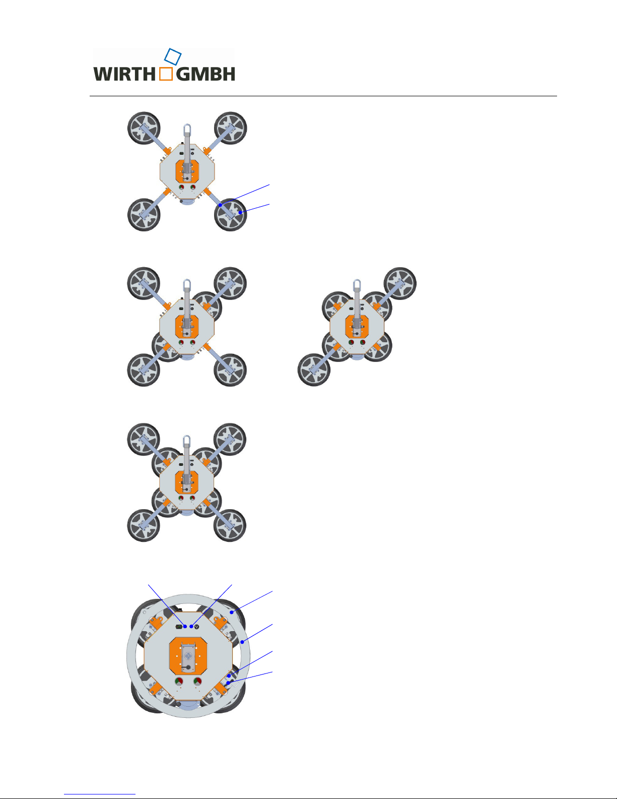
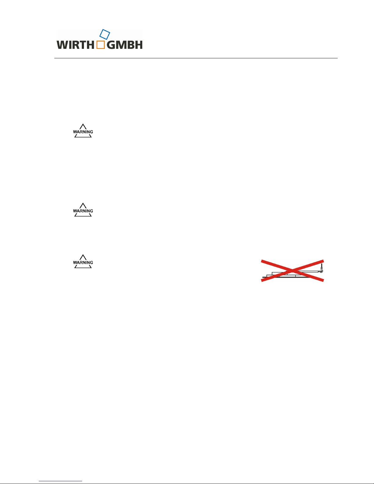
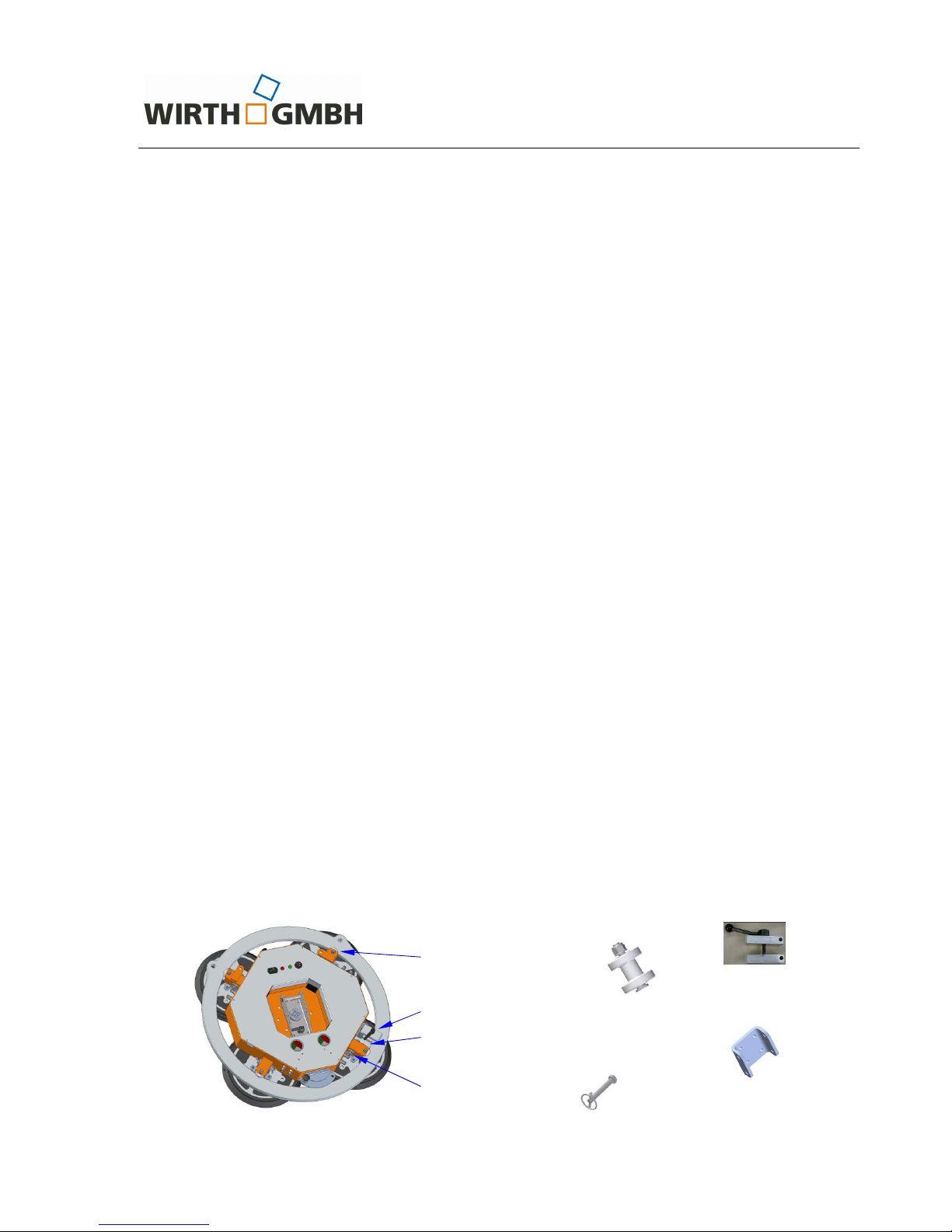
The functional main groups of components are (see fig. 1 to 5):
− the crane eyes (1, 12, 19) to connect the OKTOPUS
®
to the crane,
− the red signal light (17) indicating hazardous situations and the green signal light (18) defin-
ing the working area,
− the vacuum gauge (7) indicating the vacuum level,
− the basic frame (5) and the extension arms (17) with the suction pads fixed thereto (8),
− the charge indicator (11) permanently showing the actual charge of battery,
− the main switch (10) for switching on and the switch „Suction/Release“ (15) to operate the
OKTOPUS®.
Fig. 1: OKTOPUS
®
GLASS-Jack GL-RN 400 with crane arm
1 Crane eye of the crane arm
2 Crane arm
3 Release „Swivelling“
4 Alarm buzzer
5 Basic frame
6 Swivel joint
7 Vacuum gauge
8 Suction pad
9 Cover sheet
10 Main switch
11 Charge indicator
12 Crane eye basic frame
13 Release „Rotating“
14 Battery charge socket
15 Switch „Suction/Release“
16 Button “Blow-off“ (optional)
1
2
3
4
6
7
8
9
11
10
12
13
14
15
5
16
O p e r a t i n g I n s t r u c t i o n s
OKTOPUS® GLASS-Jack
GL-RN 400/600/800
Technical Documentation
BA 000 101
Page 9 of 27
Fig. 2: OKTOPUS
®
GLASS-Jack GL-RN 400 with crane arm and extensions
Fig. 3: OKTOPUS
®
GLASS-Jack GL-RN 600 with crane arm and extensions
Fig. 4: OKTOPUS
®
GLASS-Jack GL-RN 800 with crane arm and extensions
Fig. 5: OKTOPUS
®
GLASS-Jack GL-RN 400/600/800 with guide ring
17
8
17 Extension arm
18 Signal light red
19 Signal light green
20 Crane eye guide ring
21 Guide ring
22 Shoe brake
23 Locking lever guide ring
19 18
21
20
22
23

O p e r a t i n g I n s t r u c t i o n s
OKTOPUS® GLASS-Jack
GL-RN 400/600/800
Technical Documentation
BA 000 101
Page 10 of 27
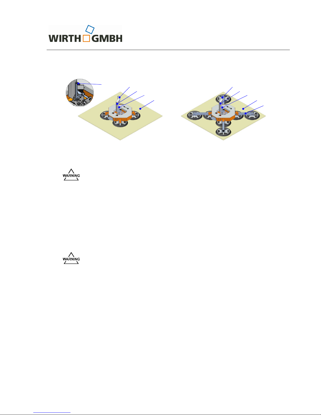
The load lifting attachment OKTOPUS® GLASS-Jack GL-RN 400/600/800 is designed as an attachment and is mounted to the crane as per fig. 6.
Fig. 6: Load lifting attachment OKTOPUS
®
GLASS-Jack GL-RN 400/600/800
Applying the load lifting attachment system OKTOPUS
®
will have the following effects on the in-
stallation of large-size glass and cladding elements:
• rapid, efficient and effective assembling procedure,
• small-sized assembly team,
• high process quality through material-preserving handling,
• low physical stress for the assembler as heavy carrying and lifting works is avoided,
• high occupational safety.
Crane arm
Lifting device
Suction pad
OKTOPUS® GLASS-Jack GL-RN 400/600/800 OKTOPUS® GLASS-Jack GL-RN 400/600/800
with crane arm
slung at the basic frame
Lifting device
Lifting device
Guide ring
OKTOPUS® GLASS-Jack GL-RN 400/600/800
with guide ring
Glass/cladding
element
Suction pad
Glass/cladding
element

O p e r a t i n g I n s t r u c t i o n s
OKTOPUS® GLASS-Jack
GL-RN 400/600/800
Technical Documentation
BA 000 101
Page 11 of 27
2.5 Conditions and restrictions of application
The glass and cladding elements to be processed with the OKTOPUS® GL-RN 400/600/800
have to fulfil the following criteria in the suction areas:
•
they have to be airtight,
• they must have a smooth, dry, oil-free and clean surface and
• they must not be equipped with a protective plastic film.
The OKTOPUS® shall be delivered with suction pads for smooth glass and cladding elements.
Generally, no statements can be made on the length and the width of the elements to be in-
stalled with the OKTOPUS
®
, as this depends - upon observing of the safe work load criteria almost exclusively on the inherent rigidity and the deformation behaviour of the construction elements connected thereto.
The suction of oil, water, vapours or aggressive gases shall be avoided. The ambient temperature shall be min 0 °C and may be max 40 °C (valid for 1013 mbar and sea level). At low temperatures the capacity of the batteries in use is reduced. The airborne sound deriving from the
OKTOPUS
®
GLASS-Jack GL-RN 400/600/800 is < 70 dB(A), vibrations are at < 2.5 m/s2, so
that no special protective measures are required.
Limitations of application arise from the limited Working Load Limit of the OKTOPUS® GLASS-
Jack GL-RN 400/600/800 (see section 2.3 Symbols and markings) as well as from the capacity
data, the conditions of application of the crane to be used and the building site conditions. Furthermore, it shall be taken into account that the element to be installed should be of sufficiently
inherent stability and appropriate for mounting by vacuum lifting attachments (to be clarified with
the elements‘ manufacturer if so).
Due to the large number of the elements existing in the market and their surface coatings, we
cannot take over liability in case of possible material incompatibilities between suction pad and
surface coating.
The maximum Working Load Limit stipulated on the OKTOPUS® only applies to the use of the
original suction pads and a working height of maximum 400 m above sea level. Employing the
OKTOPUS
®
in heights above 400 m leads to a decreased Working Load Limit of the OKTOPUS® on the one hand, on the other hand the OKTOPUS® control system needs to be adjusted. If you want to employ the OKTOPUS
®
in heights above 400 m, please contact the Wirth
Service Team beforehand.
Employing the OKTOPUS
®
at heights above 400 m leads to a decreased Work-
ing Load Limit! The Working Load Limits stipulated on the OKTOPUS
®
and in
this operating manual do not apply in this case!
Never carry out unauthorized adjustments at the control system of the OK-
TOPUS® as it may lead to serious malfunctions of the device! It means danger
to life and limb! Consult with the OKTOPUS
®
manufacturer if it is necessary to
adjust the control system of the OKTOPUS®, e.g. for height adjustment.

O p e r a t i n g I n s t r u c t i o n s
OKTOPUS® GLASS-Jack
GL-RN 400/600/800
Technical Documentation
BA 000 101
Page 12 of 27
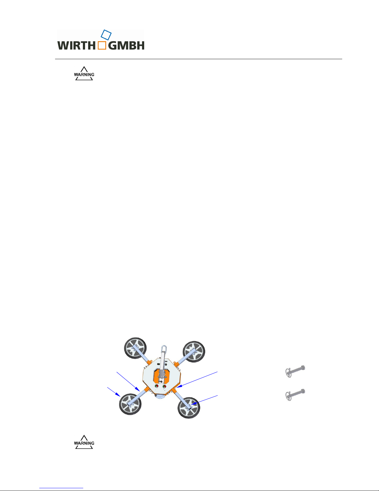
2.6 Transport and storage
The OKTOPUS® may be moved only by a suitable lifting device/means of transport of appropriate Working Load Limit.
Shut down the OKTOPUS
®
for transport! Turn the main switch to the OFF po-
sition!
Protect the rubber lip of the suction pad from pollution and damage by protec-
tion covers!
To avoid damage to the batteries by deep discharge during storage, the OK-
TOPUS
®
shall be charged every two weeks at least.
Transport rack
The transport rack shown in figure 7 is optionally available. It allows:
⇒ space-saving storage of the OKTOPUS
®
GLASS-Jack GL-RN 400/600/800 and
⇒ protecting the suction pads, especially the rubber lip during transport and storage.
Fig. 7: Transport rack
Always completely secure the OKTOPUS
in the transport rack using the
screws, washers and locking bolts with lynch pins provided in the delivery!
Locking bolt with
lynch pin
Screw M16,
washer

O p e r a t i n g I n s t r u c t i o n s
OKTOPUS® GLASS-Jack
GL-RN 400/600/800
Technical Documentation
BA 000 101
Page 13 of 27
3 Instructions for use of the OKTOPUS®
3.1 Power supply
The electrical power is provided by a battery 24 V / 7 Ah (two 12-V batteries in series connection).
The charge level is controlled by a charge indicator according to fig. 8. After switching on the
OKTOPUS
®
, light-emitting diodes (LED) in the signal colours green, yellow and red indicate the
current charging level.
The charge indicator shows the following charging status:
⇒ If one of the green LED lights up, the battery is charged. Now you can work with the OK-
TOPUS
®
.
⇒ If the third LED from the left (yellow LED) lights up, the battery should be charged.
⇒ If the second LED from the left (yellow LED) lights up or if the second LED from the left
and the red LED are alternately flashing, the battery shall be charged immediately to avoid
a deep discharge and damages.
The charge indicator is arranged according to fig. 1.
Fig. 8: Charge indicator
Do not use the OKTOPUS
®
, if the yellow LED flashes or the yellow and the red
LED are flashing alternately. An eventually sucked load should be lowered.
The OKTOPUS
®
should be immediately charged to avoid a deep discharge and
damages.
The user shall ensure that the battery of the OKTOPUS® is sufficiently charged
while operating the OKTOPUS®.
The charge indicator only shows the current voltage level of the battery that
shall not be considered as a reliable qualitative indication in terms of the batteries’ capacity.
The charge indicator reacts/responds slowly. To judge the actual voltage level
after charging (see point 4.4), the vacuum pump of the attachment needs to
run for approx. 2 minutes. The indicated charging level of the batteries allows
you to decide about the use of the attachment.
If this green LED lights up, the
battery is fully charged.

O p e r a t i n g I n s t r u c t i o n s
OKTOPUS® GLASS-Jack
GL-RN 400/600/800
Technical Documentation
BA 000 101
Page 14 of 27
3.2 Vacuum supply
The vacuum supply is provided by a vacuum pump, which is powered by electricity and supplied
by the battery. Starting from the vacuum pump, the OKTOPUS® GLASS-Jack GL-RN
400/600/800 is developed as a dual circuit system. That means, all the following vacuum modules, like non-return valve, vacuum reservoir, pressure controller, vacuum gauge and suction
pads exist twice (2 vacuum circles).
At the OKTOPUS
®
GLASS-Jack GL-RN 400/600/800 the 2 vacuum circles are marked by different colours, one colour per vacuum circuit (usually blue and red). Please note, that only vacuum hoses and vacuum hose couplings of the same colour shall be interconnected.
Mounted to the crane, the OKTOPUS
®
GLASS-Jack GL-RN 400/600/800 is ready for operation
as soon as sufficient vacuum is provided in both vacuum reservoirs. The current vacuum level is
constantly indicated via two vacuum gauges (fig. 9).
The green scale sector is the
permissible working range from -0.65 bar to -0.9 bar
Fig. 9: Vacuum gauge
During operation the vacuum is monitored by two pressure control devices. If the vacuum is in
both vacuum circles in the working area, the green signal light shines. The OKTOPUS® is ready
for use. If the vacuum descends in one or both vacuum circles below the prescribed level (pressure exceeding the -0.65 bar mark = red sector), an alarm is automatically activated:
⇒ the acoustic alarm sounds,
⇒ the red warning light flashes up.
Only interconnect vacuum hoses and couplings of the same color! Non-
compliance with these instructions could, in case of a breakdown of a vacuum
circuit, lead to the load suddenly dropping due to uneven load distribution.
If the alarm is activated, stop working instantly and evacuate the hazard zone,
as the sucked element could disengage suddenly. Never stand or walk under
the OKTOPUS
®
or the suctioned element!
The alarm remains active until the vacuum pressure is restored within its
permitted limits.
Green
sector
The OKTOPUS®
may only be operated
within this range.
Red
sector
The OKTOPUS®
must not be operated in
this range.
O p e r a t i n g I n s t r u c t i o n s
OKTOPUS® GLASS-Jack
GL-RN 400/600/800
Technical Documentation
BA 000 101
Page 15 of 27
3.3 Control panel/switch
The OKTOPUS® GLASS-Jack GL-RN 400/600/800 is operated by a control panel according to
fig. 10.
Fig. 10: Control panel
3.4 Start-up
Proceed as follows to start the operation of the OKTOPUS®:
• Place the suction pads of the OKTOPUS
®
onto the element to be sucked!
• Turn the main switch to the "ON“ position.
• Slightly lift the switch SUCTION / RELEASE, and then push it towards SUCTION!
• Check the charge level of the battery on the charge indicator,
⇒ The operational readiness is indicated through the luminescence of a green LED.
⇒ If the second LED from the left (yellow LED) flashes or the second LED from the left
(yellow LED) and the red LED flash alternately, the battery needs to be charged!
• Check the vacuum on the vacuum gauges,
⇒ if the needle of both gauges are in the green range, the unit is ready for operation!
⇒ if one or both needles are in the red range, the alarm will be activated, and the vacuum
must be built up first.
− Vacuum is built up to -0.73 bar, the red warning light goes out and the green signal
light goes on.
• Slightly lift the switch SUCTION / RELEASE and slide it towards RELEASE.
Switch
Suction/Release
Release
Main switch
Suction
O p e r a t i n g I n s t r u c t i o n s
OKTOPUS® GLASS-Jack
GL-RN 400/600/800
Technical Documentation
BA 000 101
Page 16 of 27
3.5 Handling of glass and cladding elements
First of all the OKTOPUS® GLASS-Jack GL-RN 400/600 /800 has to be coupled to the crane as
a load lifting attachment in order to get it ready for operation.
The assembly of the OKTOPUS
®
shall be carried out while the crane is immobile and the OK-
TOPUS
®
is switched off.
The assembly of the building elements is carried out as follows:
Make sure that the load is placed properly to the OKTOPUS®. Unbalanced
loads can tilt or turn unexpectedly.
3.5.1 Handling of lying glass and cladding elements
⇒ In order to suck a lying load, you need the OKTOPUS
®
GLASS-Jack GL-RN 400/600/800
in the version with a crane arm or with a crane arm and extensions (see fig. 11, ex. OKTOPUS
®
GLASS-Jack GL-RN 400 and 800).
Never use the OKTOPUS
®
with a mounted guide ring for putting up or lifting a
horizontally lying load!
⇒ Unlock the release "Swivelling" (see fig. 11) and move the crane arm with the mounted
OKTOPUS® GLASS-Jack GL-RN 400/600/800 to the elements. Place the OKTOPUS® on
the topmost element.
Never attempt to lift a horizontally lying load
if the pivoting of the crane
arm is latched!
⇒ Place the OKTOPUS
®
above the centre of mass (±5 cm) of the load.
⇒ Slightly lift the switch SUCTION / RELEASE and push it towards SUCTION (see fig. 10)
until it snaps into place.
⇒ After the warning light and the buzzer have both gone out, the vacuum gauge indicates
that the working range has been reached (see fig. 9) and you have made sure, that no
one stays in the danger area, you can lift the load.
⇒ Only lift the load as high as necessary!
⇒ After the element has been placed at the assembly location, fasten it completely to avoid
any danger after release!
⇒ After that, the building element is detached. For release, again raise the switch SUCTION
/ RELEASE a bit and push it towards RELEASE. Raising the switch is an additional safety
feature against unintentional faulty operation.
If your OKTOPUS
®
is equipped with the optional blow-off function, subsequently press the
button “Blow-off“ (see fig. 1, pos. 16). Keep the button pressed until all suction pads have
completely disengaged from the load. In this case the suction pads are supplied with
compressed air which ensures that the suction pads are released quicker from the load.
O p e r a t i n g I n s t r u c t i o n s
OKTOPUS® GLASS-Jack
GL-RN 400/600/800
Technical Documentation
BA 000 101
Page 17 of 27
Fig. 11: OKTOPUS
®
GLASS-Jack GL-RN 400 and 800 with glass element
Due to the dead weight of the OKTOPUS
®
, a residual vacuum remains even after ventilating the suction pads by the evacuated system. Jerky rising of the
OKTOPUS
®
strengthens this effect. Therefore, take the equipment always
slowly and steadily off from the elements shifted.
3.5.2 Handling of glass and cladding elements standing upright
⇒ Move the crane with the attached OKTOPUS
®
GLASS-Jack GL-RN 400/600 /800 to the
elements. Place the OKTOPUS
®
onto the topmost element.
⇒ Position the OKTOPUS
®
onto or above the centre of mass of the load (max. ±5 cm)!
In order to avoid unintended load rotation, make sure that the sliding lever
„Rotation“ (see fig. 12) is locked. The sliding lever „Swivelling“ shall be released and the crane arm be vertical !
⇒ Slightly lift the switch SUCTION / RELEASE and push it towards SUCTION (see fig. 10)
until it snaps into place.
⇒ After the warning light and the buzzer have both gone out, the vacuum gauge indicates
that the working range has been reached (see fig. 9) and you have made sure, that no
one stays in the danger area, you can lift the load.
⇒ Only lift the load as high as necessary!
⇒ After the element has been placed at the assembly location, fasten it completely to avoid
any danger after release!
⇒ After that, the building element is detached. For release again raise the switch
SUCTION/RELEASE a bit and push it towards RELEASE. Raising the switch is an additional safety feature against unintentional faulty operation
If your OKTOPUS
®
is equipped with the optional blow-off function, subsequently press the
button “Blow-off“ (see fig. 1, pos. 16). Keep the button pressed until all suction pads have
completely disengaged from the load. In this case the suction pads are supplied with
compressed air which ensures that the suction pads are released quicker from the load.
1
OKTOPUS® GLASS-Jack GL-RN 400
with glass element
1 Crane eye 4 Glass element
2 Crane arm 5 Extension arm
3 Release „Swivelling“
OKTOPUS® GLASS-Jack GL-
RN 800 with
glass element and extension arms
2
3
4
1
2
3
4
5
3
O p e r a t i n g I n s t r u c t i o n s
OKTOPUS® GLASS-Jack
GL-RN 400/600/800
Technical Documentation
BA 000 101
Page 18 of 27
Fig. 12: OKTOPUS
®
GLASS-Jack GL-RN 400/600/800 with guide ring resp. crane arm
Due to the dead weight of the OKTOPUS
®
, a residual vacuum remains even after ventilating the suction pads by the evacuated system. Jerky rising of the
OKTOPUS
®
strengthens this effect. Therefore, take the equipment always
slowly and steadily off from the elements shifted.
3.5.3 Rotating a load hanging in a vertical position with the
OKTOPUS® GLASS-Jack GL-RN 400/600/800 with a crane arm
⇒ Suck the element as described in 3.5.2!
Never unlock the release ’’Rotation“ and ’’Swivelling“ at the same time! Un-
locking both the releases may cause damages to the attachment and/or the
load!
⇒
Before rotating the load, make sure that there is enough space available. Ensure that the
load does not strike anything during rotation!
⇒
Unlock the release ’’Rotation“ (see fig. 12) and turn the load into the appropriate position.
After that relock the sliding lever.
3.5.4 Rotating a load hanging in a vertical position with the
OKTOPUS
®
GLASS-Jack GL-RN 400/600/800 with guide ring
⇒
Suck the element as described in 3.5.2!
⇒
Position the OKTOPUS® above the centre of mass of the load (max. ±5 cm).
To avoid unintended load rotation, make sure that upon use of the version
GLASS-Jack GL-RN 400/600/800 with guide ring, the eccentric lever guide ring
(see fig. 12) shall be tightened!
⇒
Before rotating the load, make sure that there enough space is available. Ensure that the
load does not strike anything during rotation!
⇒
Slowly release the eccentric lever guide ring (see. fig. 12)!
⇒
Turn the load into the appropriate position.
⇒ Engage the clamping again by moving the eccentric lever!
1 Eccentric lever guide ring
2 Show brake
3 Release „Rotation“
4 Release „Swivelling“
Hexagon bolt M20 x 140,
washer, lock nut
1 2 3 4
O p e r a t i n g I n s t r u c t i o n s
OKTOPUS® GLASS-Jack
GL-RN 400/600/800
Technical Documentation
BA 000 101
Page 19 of 27
Fig. 13: OKTOPUS
®
GLASS-Jack GL-RN 400/600/800 with guide ring, with crane arm, and
with crane arm and extension arms (6 or 8 suction pads respectively)
3.5.5 Swivelling a load hanging in a vertical position with the
OKTOPUS
®
GLASS-Jack GL-RN 400/600/800 with crane arm
⇒ Suck the element as described in 3.5.2!
Never attempt to unlock release “Swivelling“ (see fig. 12), if it carries a load.
This would cause uncontrollable “downward tilting” of the load.
In order to swivel the load from a vertical into a horizontal position, at least 3
persons are needed. Two persons have to secure and guide the load, while
the third person has to release the interlock!
⇒ Before swivelling the load you have to take into account that the swivelled load needs
more horizontal space. Make sure that the load does not strike anything during swivelling!
⇒ Unlock the release “Swivelling“ (see fig. 12) and move the load into a horizontal position.
Fig. 14: OKTOPUS
®
GLASS-Jack GL-RN 800 during swivelling
Glass element
O p e r a t i n g I n s t r u c t i o n s
OKTOPUS® GLASS-Jack
GL-RN 400/600/800
Technical Documentation
BA 000 101
Page 20 of 27
3.5.6 OKTOPUS® GLASS-Jack GL-RN 400/600/800 slung to the basic frame
As for handling standing glass and cladding elements the OKTOPUS
®
GLASS-Jack GL-RN
400/600/800 may directly be slung to the basic frame (see fig. 6). However, in this case the load
can neither be rotated nor swivelled.
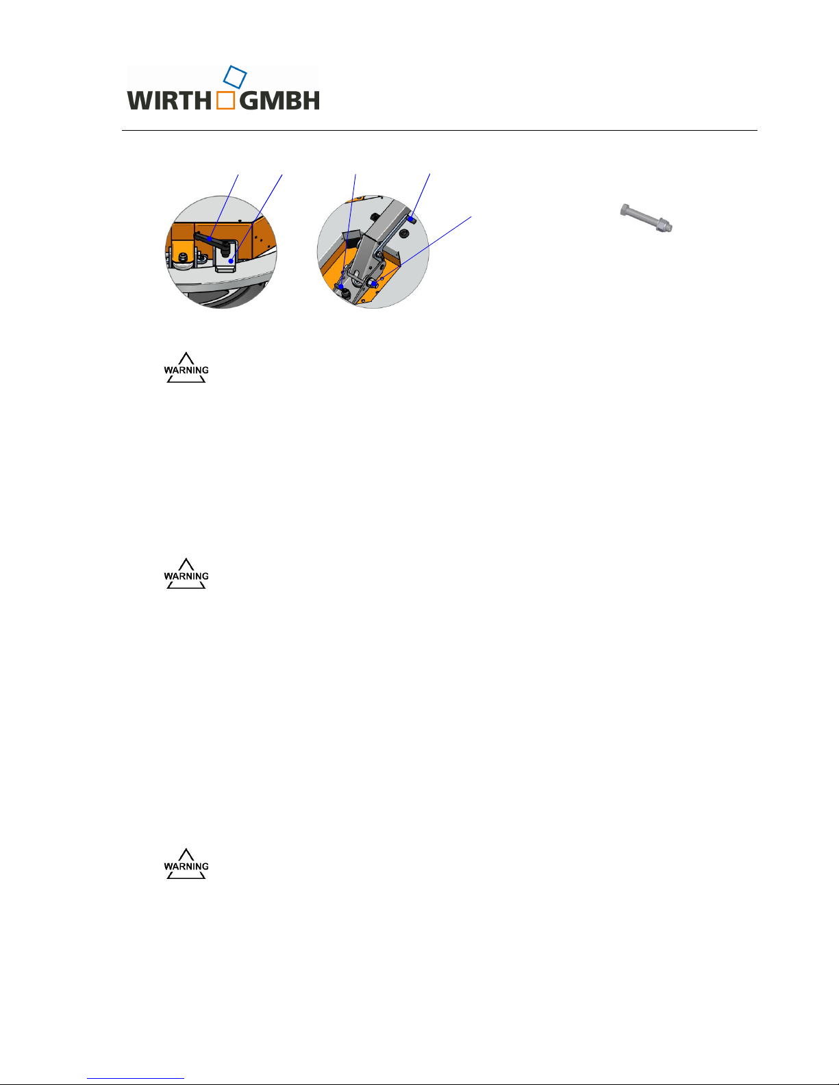
3.6 Converting the OKTOPUS® into its different versions
3.6.1 Assembly of the guide ring
⇒ Place the OKTOPUS
®
GLASS-Jack GL-RN 400/600/800 in a flat position on a clean and
even surface (suction pads are pointing down).
⇒ Dismount the crane arm. To do so remove the hexagon bolt (see fig. 12).
⇒ Dismount the extension possibly installed and any suction pads from the attachment. Re-
move the clip pin and the locking bolt to which the extensions /suction pads are fixed to
the basic frame.
⇒ Mount the guide roll completely (see fig. 14). For this use a roller pin M10, a washer and a
lock nut enclosed in the scope of supply. Insert the roller pin from bottom-up.
⇒ Push the remaining 3 guide rolls loosely into the remaining roller seats.
⇒ Put the guide ring over the basic frame and insert it into the slot of the first firmly mounted
guide roll.
⇒ Lift the guide ring and position the roll being opposite the first mounted guide roll that way,
so that it runs in the slot of the guide ring. Fix the second guide roll by means of a roller
pin M10, a washer and a lock nut.
⇒ Mount the remaining 2 guide rolls.
⇒ Mount the brake being part of the scope of supply (see fig. 12 and 15) as follows:
- If the holding plate has not yet been installed, then mount it by using the bolts M6,
washers and lock nuts forming part of the scope of supply.
- Fix the preassembled brake to the holding plate. Use the bolts, washers and lock nut
likewise enclosed in the scope of supply.
⇒ Mount the four suction pads by using the locking bolts (scope of supply). Secure each
suction pad with a clip pin.
⇒ Check again the proper seat of the guide ring, the roller seats, and the guide rolls as well
as the fixing material!
Fig. 15: Guide ring mounting
Guide roll, roller pin M10,
washer and lock nut
Locking bolts with clip pin
Brake
Brake pre-
assembled
Holding plate
brake
Roller seat
O p e r a t i n g I n s t r u c t i o n s
OKTOPUS® GLASS-Jack
GL-RN 400/600/800
Technical Documentation
BA 000 101
Page 21 of 27
Please note that after the alteration works to the OKTOPUS® any mounted
parts are always secured entirely through fixing material licensed by the manufacturer!
3.6.2 Mounting of the crane arm
⇒ Place the OKTOPUS
®
GLASS-Jack GL-RN 400/600/800 in a flat position on a clean and
even surface (suction pads are pointing down).
⇒ In case the guide ring is mounted, dismount it as well as the 4 guide rolls and the brake.
⇒ Mount the crane arm (see fig. 1) by means of the hexagon bolt M20 X 140, the washer
and the lock nut being part of the scope of supply (see fig. 12).
⇒ Mount the tension spring between the release „Swivelling“ and the crane arm.
3.6.3 Mounting of the extension arms (4 suction pads)
⇒ Place the OKTOPUS® GLASS-Jack GL-RN 400/600/800 in a flat position on a clean and
even surface (suction pads are pointing down).
⇒ In case the guide ring is mounted, dismount it as described in pt. 3.6.2.
⇒ Carry out one after another the following working steps applying to each of the four exten-
sions:
- Dismount a suction pad from the basic frame. For this disconnect it from the vacuum system by releasing the quick coupling and remove the clip pin as well as the associated
locking pin.
- Push an extension arm into the basic frame and lock it by a locking pin belonging to the
scope of supply. Secure the locking pin by a clip pin enclosed in the scope of supply, either.
- Now install the suction pad removed before to the extension arm by using the locking pin
removed before. Secure the locking pin with a clip pin.
- Couple the suction pad placed onto the extension arm to the vacuum system by inserting
the quick coupling.
Fig. 16: Mounting of the extensions (4 suction pads)
Connect only vacuum hoses resp. couplings of the same colour!
Locking pin with clip pin
Locking pin with clip pin
Extension arm
Suction pad
O p e r a t i n g I n s t r u c t i o n s
OKTOPUS® GLASS-Jack
GL-RN 400/600/800
Technical Documentation
BA 000 101
Page 22 of 27
Make sure that the locking pins are always secured entirely by the clip pins
supplied by the manufacturer!
The dismounting of the extension arms is done in reversed order.
3.6.4 Mounting of the extension arms (6 resp. 8 suction pads)
⇒ Place the OKTOPUS
®
GLASS-Jack GL-RN 400/600/800 in a flat position on a clean and
even surface (suction pads are pointing down).
⇒ In case the guide ring is mounted, dismount it as described in pt. 3.6.2.
⇒ Carry out one after another the following working steps which apply to each of the four ex-
tensions:
- Dismount the clip pin as well as the associated locking pin of one of the suction pads
fixed to the basic frame.
- Push one extension arm with suction pad into the basic frame.
- Lock the extension arm, thus locking the suction pad placed on the basic frame at the
same time with the locking pin removed before as well as with the clip pin.
- Couple the suction pad placed onto the extension arm to the vacuum system by insert-
ing the quick coupling.
Fig. 17: Mounting of the extension arms (ex. 8 suction pads)
Connect only vacuum hoses resp. couplings of the same colour!
Make sure that the lock pins are always secured entirely by the folding safe-
guard plugs supplied by the manufacturer!
The dismounting of the extension arms is done in reversed order.
Locking pin with clip pin
Suction pad
Extension arm with
suction pad

O p e r a t i n g I n s t r u c t i o n s
OKTOPUS® GLASS-Jack
GL-RN 400/600/800
Technical Documentation
BA 000 101
Page 23 of 27
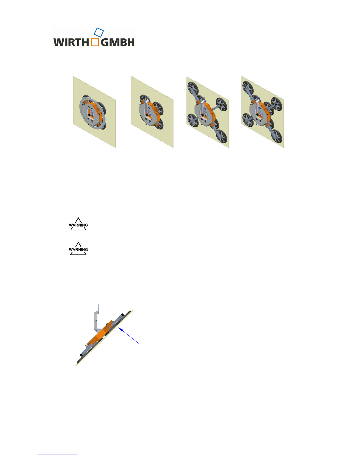
4 Servicing and Maintenance
4.1 General
As the OKTOPUS® system is a load lifting attachment, the manufacturer and operator bear
great responsibility for ensuring a high standard of safety during the entire operation of the unit.
For this reason, servicing and maintenance are of prime importance.
In order to maintain a high level of operational safety the OKTOPUS
®
GLASS-Jack GL-RN
400/600/800 must be inspected by the service centre of Wirth GmbH or a specially qualified
technician:
⇒ at least every 12 months or at shorter time intervals, if required by national standards or
regulations or
⇒ after any special incidents.
Any operative and scheduled servicing, maintenance and repair work exceeding this inspection
should be carried out by trained and skilled staff only.
Servicing and repair work should only be carried out when the machine is out of operation.
Before performing any repair or maintenance work on the OKTOPUS
®
switch
the entire unit off. Turn the main switch to the “OFF” position.
For the exchange of faulty parts only original spare parts shall be used. These will be supplied
after consulting the service centre of the OKTOPUS manufacturer upon request. The manufacturer will not accept any liability in the event of installation of anything but original spare parts.
Only use suitable tools to perform repair and maintenance work.
Always carry out a functional test after completing repair works.
In case of faults, which cannot be remedied by in-house personnel, please contact the Wirth
GmbH service centre.
4.2 Mechanical components
The mechanical components are sturdy and provided with a surface protection. Maintenance
work on your side comprises:
⇒ daily inspection of the mechanical components of the OKTOPUS
®
GLASS-Jack GL-RN
400/600/800 to detect any damage before starting the operation of the unit.
The OKTOPUS
®
GLASS-Jack GL-RN 400/600/800 is a load lifting attachment. Therefore, re-
pairs to the mechanical function components can only be carried out by the OKTOPUS
manu-
facturer.
Never carry out any repair work on the mechanical function components!
O p e r a t i n g I n s t r u c t i o n s
OKTOPUS® GLASS-Jack
GL-RN 400/600/800
Technical Documentation
BA 000 101
Page 24 of 27
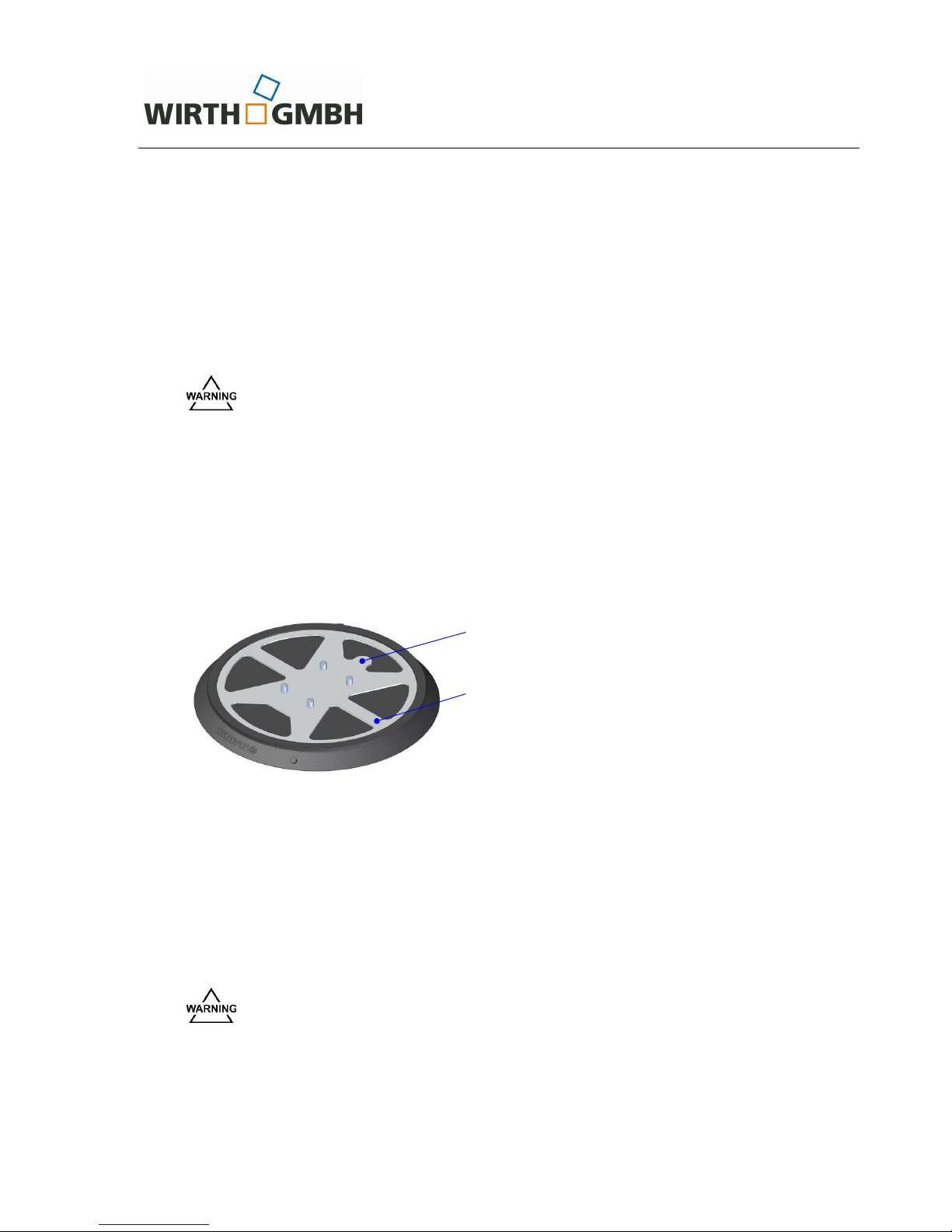
4.3 Vacuum system
Vacuum components, which are subject to wear and relevant to safety, must be inspected on a
regular basis. For this purpose:
⇒ Daily check the components in terms of their correct position and mechanical damages, in
particular:
• the suction pads (replace suction pad(s) if so),
• the hoses,
• the vacuum gauges.
Replace the suction pads and the hoses immediately if these have mechanical
damages (cracks, cuts, etc.)! These damages could lead to a reduced Working
Load Limit of the OKTOPUS
®
.
The vacuum pump runs completely oil-free. The robust design allows a maintenance-free operation.
The infiltration of dust into the vacuum pump is prevented by a filter screwed in into each individual suction pad. Therefore, maintenance of the vacuum system is focused on this component.
⇒ Slightly lift the OKTOPUS
®
without the load. The filter is in the through-hole to the connec-
tion of the vacuum hose. Dirty filters shall be cleaned.
Fig. 18: Suction pad
4.3.1 Cleaning the suction pads
Always clean the suction pads prior to every operation of the OKTOPUS
®
, if the suction areas
are soiled (dirt, dust, oil, etc.). Dirt could cause leakages and leave marks on the manipulated
elements.
For cleaning the suction pads we recommend to use water, if necessary add some detergent.
Do not use chemical solvents, petrol, diesel oil or similar in any case.
Never use solvents, petrol or aggressive chemicals for cleaning the suction
pads! Otherwise this may result in damaging the suction pads, which could
endanger the operator as well as others.
Ensure that fluids cannot enter the vacuum system during the cleaning process by positioning
the suction pads or by covering the suction opening. Give the suction pads a sufficient amount
of time to completely dry before operating the OKTOPUS
®
.
Filter (connection vacuum hose)
Suction pad
O p e r a t i n g I n s t r u c t i o n s
OKTOPUS® GLASS-Jack
GL-RN 400/600/800
Technical Documentation
BA 000 101
Page 25 of 27
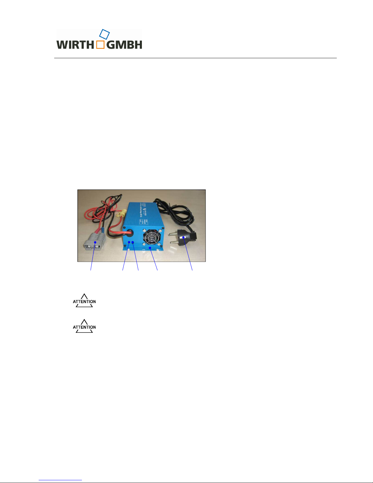
4.4 Electrics and electrical components
The OKTOPUS® GLASS-Jack GL-RN 400/600/800 is running with a maintenance-free lead-gel
battery (acidic). The battery casing is hermetically sealed.
Maintenance focuses on:
⇒ daily inspection of the external electrical functions and alarm devices:
• Alarm signal,
• Signal light,
• Alarm buzzer.
⇒ checking the charging level of the battery on the charge indicator (see fig. 8).
⇒ battery charging
A 24 V / 5 A charger for charging the battery is supplied by the OKTOPUS
®
system manu-
facturer (see fig. 19).
Fig. 19: Battery charger (sample)
Before connecting the charger to the power supply, check whether appropri-
ate! The respective data of capacity you will find on the charger.
In case you want to use a charger other than the one belonging to the OK-
TOPUS
®
scope of supply, it becomes essential to contact the Wirth Service
Team in advance!
The battery has to be charged as follows:
• Switch off the OKTOPUS
®
. For this turn the main switch to „OFF“ position!
• Connect the charger plug to the battery socket for charging OKTOPUS
®
.
• Connect the power plug of the charger to the power supply via socket to start the
charging procedure.
• The charging is finished as soon as the yellow LED lights up permanently.
• Proceed as follows to disconnect the charger from the OKTOPUS
®
:
1. Disconnect the charger from the power supply,
2. Separate the connection between charger and battery.
1 2 3 4 5
1 Charge plug charger
2 Yellow LED
3 Green LED
4 Battery charger
5 Main plug

O p e r a t i n g I n s t r u c t i o n s
OKTOPUS® GLASS-Jack
GL-RN 400/600/800
Technical Documentation
BA 000 101
Page 26 of 27
LED display
⇒ The green LED will be on when the charger is connected to the mains supply.
⇒ The yellow LED will flash at a fast rate during bulk charge and at a slower rate during ab-
sorption charge. The yellow LED will be continuously on after the charging is complete.
Please contact the Wirth service centre for maintenance and in the event of failure of the
charger.
The sealed lead-gel battery entails the absolute observation of the charging
instructions!
In order to prevent the battery from destruction caused by deep discharging,
the OKTOPUS
®
should be recharged at least every two weeks.
The charger shall be protected against splash and installed in such a position
that the ventilator and the ventilation slots are not covered and cannot be
penetrated by sharp objects.

O p e r a t i n g I n s t r u c t i o n s
OKTOPUS® GLASS-Jack
GL-RN 400/600/800
Technical Documentation
BA 000 101
Page 27 of 27
5 Conduct in the event of hazardous incidents
In the event of hazardous incidents the acoustic alarm sounds and the red warning lamp lights
up. The total failure of the electric power supply is signalled by a fading sound of the alarm
buzzer.
Fig. 20: Warning devices
In case the alarm buzzer sounds and/or the red warning light flashes, immediately leave the
danger area, since the sucked elements could suddenly drop down. The cause for the alarm
should be found and removed. In case the defects cannot be removed, stop working with the
OKTOPUS
®
immediately. After releasing a possibly sucked element the OKTOPUS® shall be
secured against further use.
In case of faults that cannot be remedied, working with the OKTOPUS
®
shall
be stopped immediately. Der OKTOPUS
®
shall be secured against further use.
If there is no indication is given on the charge indicator when the OKTOPUS
®
is switched on,
always contact the Wirth GmbH service centre of immediately.
6 Disposal and Recycling
For the packaging of the OKTOPUS®, materials like wood, cardboard, paper and film are used.
These materials shall be recycled according to national regulations.
To dispose the OKTOPUS
®
, hand it in to a waste management company. If you have any ques-
tions, please do not hesitate to contact Wirth GmbH.
For environmental reasons hand over the OKTOPUS
®
for disposal to a waste
management company being fully aware and observing the national regulations!

O p e r a t i n g I n s t r u c t i o n s
OKTOPUS® GLASS-Jack
GL-RN 400/600/800
Technical Documentation
BA 000 101
Annex 1
Abridged operating instruction
OKTOPUS
®
GLASS-Jack GL-RN 400/600/800
1 Assembly
(1) Configurate the OKTOPUS® in correspondence with the application, and fix to the crane
hook.
2 Start-up of the OKTOPUS®
(1) Place the OKTOPUS® onto the element to be sucked.
(2) Turn the main switch to ON position.
(3) Slightly lift the switch „Suction/Release“ and push towards „Suction“.
(4) Check the charging status of the battery via charge indicator.
• the green LED shows readiness for operation,
• when the third LED from the left (yellow LED) lights up, the battery should be charged,
• when the second LED from the left (yellow LED) flashes or the second LED from the left
(yellow LED) and the red LED light up in turns, the battery must be charged.
(5) Check vacuum pressure at the vacuum gauge (permissible green sector -0.65 to -0.9 bar):
• In case pressure in one or in both gauges is in the red sector, the alarm will be activated
and vacuum needs to be built up.
• If pressure in both vacuum gauges is in the green area, the OKTOPUS
®
is ready for op-
eration; the red signal light switches off and the green signal lamp turns on.
3 Instruction for use
(1) Preparation of the elements:
• Check the surface of the element: The surface shall be smooth, airtight, clean and dry
at least at the suction spots. There must not be any protection film in the suction area.
(2) Lifting the element:
• Place the OKTOPUS
®
onto the element.
• Slightly lift the switch „Suction/Release“ and push towards „Suction“.
(3) Positioning the element:
• Erect/lift the element by crane lifting movement,
• Positioning of the element by crane driving and lifting movement together with simulta-
neous manual guidance of the element by the installer.
• Fixation of the element to the installation point.
(4) Detaching the element
• Slightly lift the switch „Suction/Release“ and push towards „Release“.
4 Shutdown
• Lower the crane.
• Separate the connection OKTOPUS
®
/ crane.
• Turn the main switch of the OKTOPUS
®
to OFF position.
• In case of shutdown over a longer period, the batteries of the OKTOPUS
®
shall be
charged at least every 2 weeks.

O p e r a t i n g I n s t r u c t i o n s
OKTOPUS® GLASS-Jack
GL-RN 400/600/800
Technical Documentation
BA 000 101
Annex 2
Functional dimensions
1450 mm
1890 mm
230 mm
860 mm
1050 mm
230 mm
140 mm
860 mm
1050 mm

WIRTH
MBH
e
NG
Operatino
I nstructions
OKTOPUöC
GLASSJacK
GL-RN 400/600/800
.
Technical Documentation
BA
000 101
Annex 3
Declaration
of Conform
ity
Pursuant
to Appendix ll A
of the EU
machinery
directive 20061421EC
Manufacturer:
WIRTH
GMBH
Vacuum
lifting technology
division
Brehnaer
Straße 1
D-06188
Landsberg
Germany
Herewith
we
declare
that the machine hereinafter
described is in
conformity with any
provisions
relevant
to the
EU machinery
directive20Q6l42lEC:
Productdescription:
OKTOPUS@GLASS-JackGL-RN400/600/800
Type:
oKTOPUS@
ctnss-Jack
GL-RN 400/600/800
R M F,24 p 110
Serial number:
A
L{o
}+Z
Yearof
manufacture:
O"
lZoÄ-l
In
addition
the
partly
completed machinery is
in
conformity with
the
EC
directive concerning
the minimum
safety
and health
requirements
for
the use
of work
equipment by work-
ers
at
work
2O09l104lEC,
the EG
directive
on
product
safety 2001/95/EC
and
the
EC
di.
rective
on electromag
netic com
patibi
lity 201 4130/E
U.
Harmonized
standards
applied :
DrN
EN tSO 12100
(03/11)
Safety
of machines
-
General
principles
of Design
-
Risk
assessment
and Risk reduction
DrN EN tSO
13857
(06/08)
Safety of
machinery
-
Safety distances
to
prevent
hazard
zones
being reached
by upper
and
lower
limbs
DIN EN
60204
Part
,|
(06107)
Electrical
equipment
of machines
-
General requirements
DtN
EN 13{55
(08/09)
Crane
-
Safety
-
Non-fixed load
lifting
attachment
Authorized
staff
to compile the
relevant technical
documents:
Mr.
Sven Röthe,
Brehnaer
Straße 1, D-06188
Landsberg
This
declaration
solely corresponds
to the machine
in
the status as
put
on the market; any
parts
additionally installed
and/or
modifications
additionally
carried
out by the
end user shall
be unconsidered.
This
declaration will
become invalid,
in
case the
product
should be
modi-
fied without
our approval.
Landsberg,
at
.
O
0.2oa7
.11
r.-
.
L
r\.
Holger
Schadwinkel
(Managing
Director)

O p e r a t i n g I n s t r u c t i o n s
OKTOPUS
®
GLASS-Jack
GL-RN 400/600/800
Technical Documentation
BA 000 101
Annex 4
Test badge for the
OKTOPUS
®
GLASS-Jack GL-RN 400/600/800
Pursuant to the Directive 2006/42/EU
Plate dimensions: 80 x 40 mm
Background: blue
Foreground: white
Script: white on blue
Badge dimensions: diameter 30 mm
Background: depending on the year
Foreground: depending on the year
201
7
O p e r a t i n g I n s t r u c t i o n s
OKTOPUS® GLASS-Jack
GL-RN 400/600/800
Technical Documentation
BA 000 101
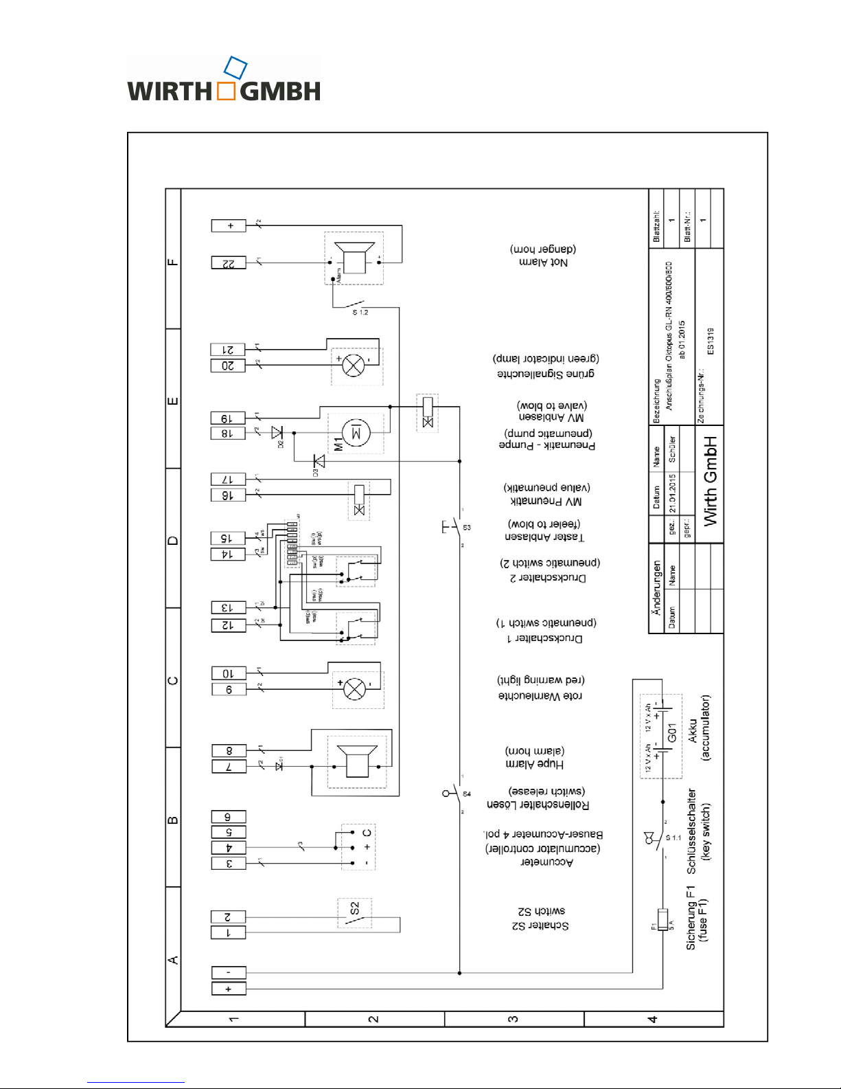
Annex 5
Electrical Circuit Diagram
 Loading...