

Page 1
3-WIRE
THERMOSTATS
for Radiant Heating
APPLICATION
Wirsbo Thermostats are the first digital thermostats
designed specifically for use in hydronic radiant
heating applications. Wirsbo provides a specific
model for 3-wire operation.
A3030103 – Heat Only, 3-wire
DEFINITION
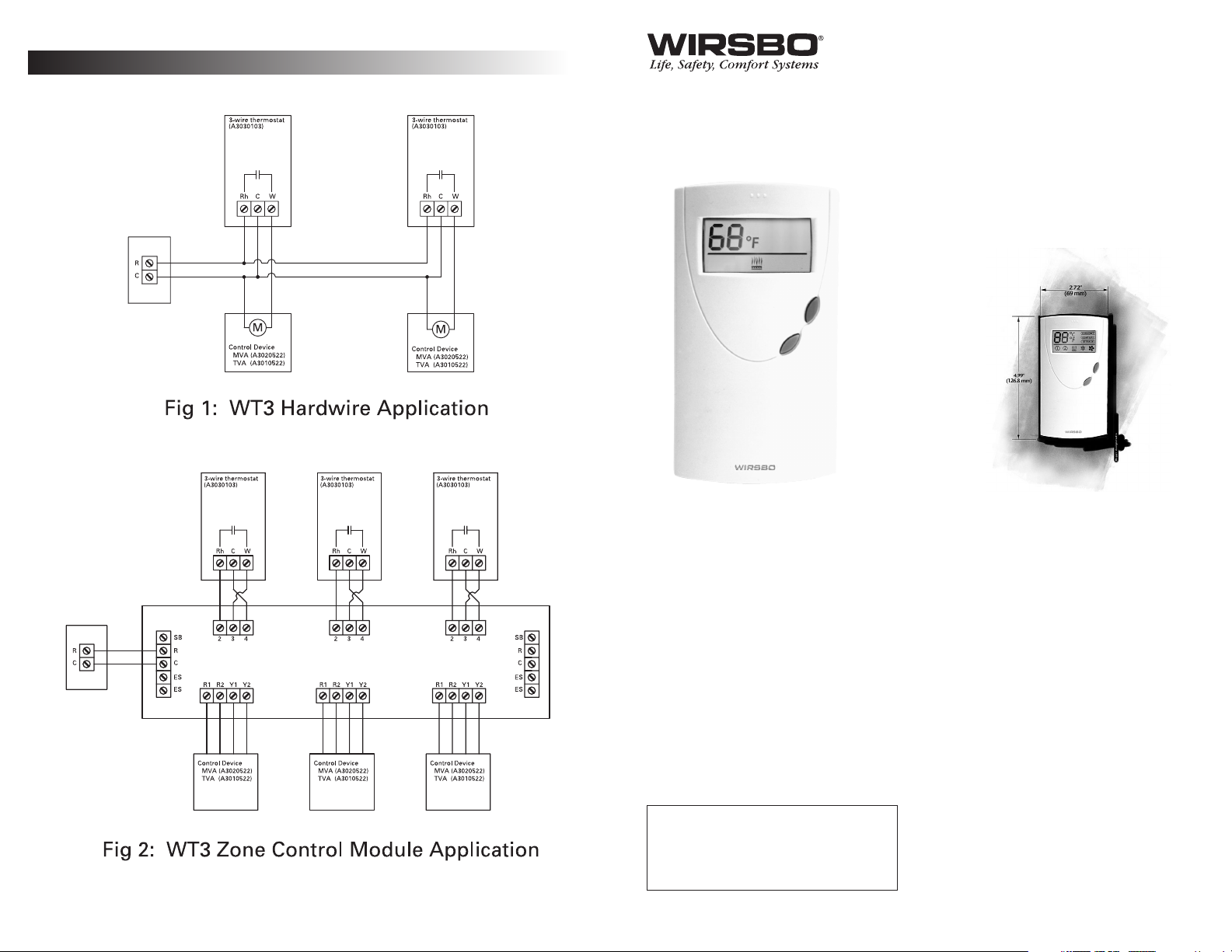
The 3-wire version eliminates voltage drop through
the thermostat and provides a full 24 volts to the
associated control device (relay, zone valve, etc.). The
3-wire thermostat can be used in any installation
where power-stealing thermostats pose operational
or compatibility issues. The R and C terminals
provide a continuous power supply to the thermostat
at all times. The heat demand is switched through
terminals R and W and is a “dry” contact. See Wiring
Schematics for additional information.
TOOLS REQUIRED
• Small, flat heat screwdriver
• Phillips screwdriver (mounting hardware)
• Wire cutter/stripper
SPECIFICATIONS
• Operating Voltage
24VAC+/-10%
• Maximum Load
1.3A @ 24VAC
(4 MVAs, p/n A3020522)
(6 TVAs, p/n A3010522)
• Display Range
32 to 99°F (0 to 37°C)
• Setpoint Range
40 to 99°F (4 to 37°C)
• Resolution
1° Displayed
0.25° Calculated
• Temperature Ranges
14 to 158°F, Shipping
(-10 to 70°C)
32 to 104°F, Ambient
(0 to 40°C)
• Humidity
40-90% non-condensing
• Size
5.0"H x 2.72"W x 0.91"D
• Weight
0.22 lbs.
INSTALLATION
Prior to installing a Wirsbo Thermostat:
a. Familiarize yourself with the product by
reading the instructions. Failure to do so could
result in damage to this product, yourself or create
a potentially hazardous situation.
b. Make sure that the function and rating of this
product are suitable for the intended use.
c. The installer must be an experienced, trained
professional familiar with low voltage wiring
d. Wirsbo recommends using 18AWG wiring for all
low voltage wiring connections.
LOCATION
Thermostat placement is extremely important. Install
Wirsbo Thermostats approximately 5 (five) feet
above the floor on a smooth, flat surface. Avoid
mounting the thermostat in the following locations:
• Near or around windows
• On outside walls
• Near fireplaces
• In the corner of a room
• Behind doors
• On interior walls susceptible to solar gains
• Near stoves, lamps, televisions, etc.
• Damp areas
• Dimmer Switches
Typical Wiring Schematic
NOTE: For the most common applications,
please review the schematics in this
document. For additional help, please call
our Technical Department @ 888-594-7726.
Page 2
MOUNTING THE THERMOSTAT
TO THE WALLPLATE
a. Place the tabs at the bottom of the front enclosure
into the grooves at the back of the wallplate.
b. Check for alignment between the two components.
c. Apply pressure to the top of the thermostat face
until a "click" is heard.
WIRING
All wiring must comply with local
electrical code and specification.
a. Remove 3/8" of wire insulation on the wire ends. Make
sure the bared wires are clean and free of corrosion.
b. Route the wires to the terminal block(s) and place
the end of wires in the correct wiring location.
(See section on wiring).
Caution:
Disconnect the electrical power to the
system to prevent electrical shock.
SETTING AND ADJUSTING
Wirsbo Thermostats are designed to
operate all functions with 2 buttons
("+" & "-") on the front of the
thermostat case.
Power Up/Power Interruption
—
After all electrical connection are
complete and the thermostat is
properly mounted, power can be
applied to the system. The
thermostat defaults to a room set
temperature of 68°F and the Heating
mode of operation when the power
is first applied. The thermostat will
save the last temperature setting if
power is interrupted.
Normal Operation
— The current
room temperature measured by the
thermostat is displayed during
normal operation along with the
mode of operation. The mode of
operation is indicated on the display
by the following icons:
• None — Thermostat is turned off.
• Radiant Panel — Heat mode, no call
for heat
• Radiant Panel w/lines flashing above —
Heat mode, call for heat.
Making the room warmer or cooler
(Temperature Adjustment)
—
Pressing the + (increase)
and - (decrease) buttons will
change the desired room
temperature setting.
a. Press either button to enter
the programming mode.
b. The icon showing mode of
operation will start to flash.
c. Press the "+" button to increase the
room temperature and "-" to lower
the temperature. Press and hold
the button to rapidly change the
temperature setting.
d. Any change is accepted 5 seconds
after the last button is pressed and
reverts to displaying the current
room temperature.
Switching from Heating to
Off (Mode Selection)
—
Wirsbo Thermostats do not require
a switch to change the thermostat
over from heating to off (or standby).
a. Press both buttons simultaneously
to change the mode of operation.
b. Make sure the program bar is
flashing to indicate you are in the
programming mode.
c. Press either button to change the
mode of operation. Using the “+”
button versus the “-” will only
change the rotation sequence of
the icons or modes.
d. The mode of operation is
indicated by the following icons:
• None
— The thermostat is turned off
• Floor Icon
— Heating Mode
e. Any change is accepted 5 seconds
after the last button is pressed and
reverts to displaying the current
room temperature. The program
bar stops flashing and is shown as
a solid bar.
Figure 1: Thermostat display indicating call heat.
Important:
Both the Heat Only
and Heat/Cool thermostats will
return to Heat Mode when
power is shut off or interrupted
Note:
The room temperature
setting cannot be adjusted
when the mode is set to off.
IMPORTANT
• This product is not designed for use in heating applications
with forced air furnaces.
• Thermostats conform to universal industry standards.
Wirsbo IS NOT responsible for damages resulting from
misapplication or misuse of its products.
• Thermostats must be installed with the power supply
disconnected. Failure to do so can result in damage to the
thermostat.
OPERATION
The dynamics of a radiant heating
system differ from typical baseboard
or warm air heating systems.
Radiant systems always heat objects
and mass and need to be addressed
differently than conventional
thermostat logic. The Wirsbo
Thermostats have 2 different control
methods to handle this condition:
• Differential
— When the measured
room temperature falls 1°F (0.5ºC)
below the desired room setting, the
control devices wired to the
thermostat are turned on.
• Pulse Width Modulation
(PWM)
— When the condition
exists where the room temperature
is 1-3°F (0.5-1.5ºC) below the room
setting, the thermostat manages the
on and off cycle using PWM. The
on and off times will vary
depending on the difference
between room and set temperature;
the further away, the longer the on
time. This prevents the room
temperature from rising above the
set temperature. The heating
system will run continually at room
temperature differences greater
than 3°. This is important to
understand for this reason:
When the thermostat is in PWM
mode, the heating icon may be
flashing but the heating equipment
will be turned off.
•
Digital Filtering
— Room
temperature is measured
continually using the WT series
thermostats. Even the smallest
change will be detected by the
thermostat’s sensor and is better
able to react a room’s changing
conditions. If all of the room’s
temperatures were displayed as
they are sensed, the temperatures
shown would appear erratic
and inconsistent. By filtering, or
throwing out the values that do
not make sense, the display and
operation becomes smoother.
Figure 2: Thermostat with all
icons and segments displayed.
Note:
Room temperatures
can take up to a minute to
change 1°F (0.5ºC) due to
filtering.
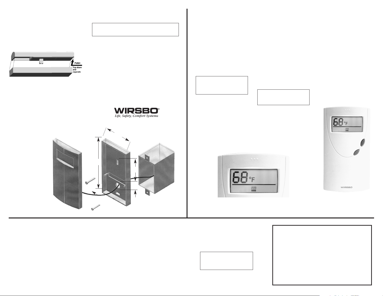
MOUNTING THE WALLPLATE
To begin, separate the front and back plates of
the thermostat. Wirsbo Thermostats are opened
by applying gentle pressure downward on the
front half and separating from the back. The
thermostat case is designed to fit (and mount)
directly too a standard electrical wall box or can
be directly wall mounted on most surfaces using
suitable hardware.
a. Pull the thermostat wire through the round
opening in the back plate.
b. Place the backplate against the wall at the
desired location in order to cover the open or
electrical wall box. Make sure the round
opening for the is in the lower half of the case.
c. Align the holes of the backplate to the holes in
the electrical wall box and attach using
suitable hardware.
d. If mounting on
drywall, use wall
anchors and screws
(or other suitable
material) and attach
accordingly.
e. If the wall cavity
behind the thermostat
is susceptible to drafts
(return air plenum),
plug and seal any
openings to prevent
them from affecting
temperature reading.
18 AWG, 2 Cond.
Stranded
2.72"
(69mm)
5.00"
(127mm)
2.5"
(63.5mm)
.75"
(19mm)
 Loading...