

Page 1
WiRobot X80 USER MANUAL
WiFi 802.11 Wireless Mobile System
Version: 1.0.4
Oct. 2005
Page 2

Table of Contents
Chapter I.
WiRobot Getting Start Guide........................................................................................... 4
I. Preface............................................................................................................................................................... 5
I.1 Audience.................................................................................................................................................... 5
I.2 Feedback................................................................................................................................................... 5
II. WiRobot Overview..........................................................................................................................................6
II.1 Software Components ........................................................................................................................... 7
III. Software (WiRobot SDK) Installation ........................................................................................................8
III.1 System Requirements ............................................................................................................................ 8
III.2 WiRobot System Installation................................................................................................................ 8
IV. Connecting to WiRobot System...................................................................................................................9
IV.1 WiFi Wireless Connecting......................................................................................................................9
IV.2 Serial Cable Connecting .......................................................................................................................10
V. Building PC Applications Using SDK......................................................................................................... 12
V.1 Using WiRobot SDK Component ActiveX Control ........................................................................ 12
V.2 Sample Application 1 – WiRobot X80 Controller (VB) ................................................................ 14
V.3 Sample Application 2 - WiRobot DRK8000 Controller (VB)..................................................... 16
V.4 Sample Application 3- WiRobot DRK6000/8000 Controller (VC++).....................................16
V.5 Other Sample Applications.................................................................................................................. 17
VI. Miscellaneous................................................................................................................................................. 17
VI.1 System Update ...................................................................................................................................... 17
Chapter II. X80 System Specification.............................................................................................. 18
I. WiRobot X80 Overview ..............................................................................................................................19
Standard Electronics components and Operation Detail......................................................................... 21
I.1 Mechanical Specification.....................................................................................................................23
I.2 Electrical..................................................................................................................................................23
I.3 Other Specification ...............................................................................................................................25
II. Miscellaneous ................................................................................................................................................ 25
II.1 Battery Recharging...............................................................................................................................25
II.2 Sensor Location.....................................................................................................................................25
II.3 Known Issues..........................................................................................................................................25
Chapter III. WiRobot SDK Application Programming Interface (API) (For MS Windows) ........26
I. Convention ..................................................................................................................................................... 27
II. WiRobot SDK Overview .............................................................................................................................28
III. WiRobot SDK API Reference for PMS5005 ........................................................................................ 30
III.1 Sensor Peripherals............................................................................................................................... 30
III.2 Motion Control ......................................................................................................................................44
III.3 Multimedia Control ...............................................................................................................................60
III.4 Events .....................................................................................................................................................60
IV. WiRobot SDK API Reference for PMB5010 .........................................................................................61
Copyright © Dr Robot Inc. 2005
1
Page 3

Multimedia Control................................................................................................................................ 61
IV.1
IV.2 Events .....................................................................................................................................................64
V. WiRobot DRK6080/6000/8080/8000 Specific APIs ..................................................................65
V.1 Low Level Protection.......................................................................................................................... 65
Chapter IV. WiRobot Module ..............................................................................................................66
I. PMS5005 Sensing and Motion Controller............................................................................................. 67
I.1 Introduction ............................................................................................................................................67
I.2 Operations ............................................................................................................................................. 69
I.3 Procedure to upgrade the PMS5005 firmware ............................................................................76
II. PMB5010 Multimedia Controller .............................................................................................................80
II.1 Introduction ...........................................................................................................................................80
II.2 Operations .............................................................................................................................................. 81
II.3 Procedure to upgrade the PMB5010 firmware ............................................................................ 85
III. MDM5253 DC Motor Driver Module with Position and Current Feedback.................................... 88
III.1 Introduction ...........................................................................................................................................88
III.2 Operations ............................................................................................................................................. 88
III.3 Connections ...........................................................................................................................................90
III.4 Specifications ......................................................................................................................................... 91
IV. WFS802b WiFI 802.11 Serial Module with antenna .......................................................................... 93
IV.1 Introduction ........................................................................................................................................... 93
IV.2 Operations ............................................................................................................................................. 93
IV.3 Connections ........................................................................................................................................... 93
IV.4 Specifications........................................................................................................................................ 95
IV.5 Configuration via Serial Mode or Telnet Port................................................................................ 96
IV.6
Configuration using Web- Manager
................................................................................................... 116
V. MCB3100 WiRobot Serial Bluetooth Wireless Module.................................................................... 128
V.1 Introduction ......................................................................................................................................... 128
V.2 Operations ........................................................................................................................................... 128
V.3 Connections ......................................................................................................................................... 129
V.4 Specifications...................................................................................................................................... 130
VI. MAC5310 Audio Codec and Audio Power Amplifier Module............................................................ 131
VI.1 Introduction .......................................................................................................................................... 131
VI.2 Operations ............................................................................................................................................ 131
VI.3 Connections .......................................................................................................................................... 131
VI.4 Specifications.......................................................................................................................................132
VII. DUR5200 Ultrasonic Range Sensor Module...................................................................................... 134
VII.1 Introduction ......................................................................................................................................... 134
VII.2 Operations ........................................................................................................................................... 134
VII.3 Connections ..........................................................................................................................................135
VII.4 Specifications.......................................................................................................................................136
VIII. DTA5102 Two-Axis Tilt and Acceleration Sensor Module ...............................................................137
VIII.1 Introduction .......................................................................................................................................... 137
VIII.2 Operations ............................................................................................................................................137
VIII.3 Connections ..........................................................................................................................................139
Copyright © Dr Robot Inc. 2005
2
Page 4

Specifications...................................................................................................................................... 140
VIII.4
IX. DHM5150 Human Motion Sensor Module............................................................................................141
IX.1 Introduction .......................................................................................................................................... 141
IX.2 Operations ............................................................................................................................................ 141
IX.3 Connections ......................................................................................................................................... 142
IX.4 Specifications...................................................................................................................................... 143
IX.5 Fresnel Lens ........................................................................................................................................ 143
X. DAT5280 Ambient Temperature Sensor Module.............................................................................. 144
X.1 Introduction .........................................................................................................................................144
X.2 Operations ........................................................................................................................................... 144
X.3 Connections......................................................................................................................................... 145
X.4 Specifications...................................................................................................................................... 146
Chapter V. TROUBLE SHOOTING ................................................................................................. 147
Copyright © Dr Robot Inc. 2005
3
Page 5

Chapter I. WiRobot Getting Start Guide
Copyright © Dr Robot Inc. 2005
4
Page 6

I. Preface
I.1 Audience
This document is written for robot developers in using WiRobot systems. It provides the initial
product information as well as a guide in helping users to understand how to use this system. The
developers should have basic knowledge in Microsoft Visual C++ or VB. Detail programming
information can be found in Chapter III.
I.2 Feedback
If you find any problems in this document, please send us your feedback to [email protected].
Copyright © Dr Robot Inc. 2005
5
Page 7

II. WiRobot Overview
WiRobotTM is an integrated electronic and software robotic system extended from Dr Robot’s
comprehensive humanoid robot, which has demonstrated its interactive capabilities in the public and
the media. Each WiRobot development system is designed to provide a user-friendly programming
environment for hobbyists, students in robotic areas and researchers to develop their robot programs
and applications at an affordable cost.
The power of WiRobot mobile robot system comes from the Dr Robot’s Distributed Computation
Robotic Architecture and System (DIRAS) technology, which offloads most of the computation and
storage intensive tasks to a home PC. Through a digital wireless connection supporting over 100kbps
data communication rate, user programs running on PC are virtually connected directly to the
WiRobot development system. Data such as image, audio, sensor information, and etc. are available to
the user through a set of ActiveX control components (SDK) developed for MS VC++ and VB
programming environment. Multiple PC programs are also allowed to access the data information
obtained from the sensors simultaneously. High level schemes such as tele-operation, navigation,
reasoning, learning, recognition, and image processing routines are programmed and executed on the
PC remotely. Multi-robot coordination is also feasible for applications like soccer game. Microsoft
Visual Studio programming environment is chosen as the development platform due to its popularity
and ease-of-use than the non-user friendly embedded programming interface. Note that
communication protocol for WiRobot system is also available for developers/researchers who prefer
to use different platform or operating systems to communicate and control the WiRobot system. But
this document focuses on how to use the WiRobot system using the SDK under Microsoft platform.
As well, WiRobot system already comes with low-level drivers for all its electronic modules and can
provide a flexible way for users to control the robot. For instance, it allows user to control standard
servo motors and DC motors by using the built-in commands available in the control command library,
which offers several types of DC motor control method including open-loop PWM, closed-loop
position control, closed-loop velocity control, and closed-loop current control. Control parameters are
also configurable.
Copyright © Dr Robot Inc. 2005
6
Page 8
II.1 Software Components
The WiRobot system comes with a CD containing the following software components and documents:
. “WiRobot Gateway” which is used to connect the PC to the robot and show the connection
status,
. An ActiveX control, called WiRobot SDK ActiveX Module, with a set of APIs is provided for
user to access the robot when developing his/her own applications in MS VC++ or VB,
. Several PC sample applications with source code is provided to demonstrate the capabilities
of the WiRobot system, and
. WiRobot documents. (The latest documents can be found on www.drrobot.com
In the WiRobot system, low level electronic drivers are pre-programmed and embedded in the
WiRobot controllers (PMS5005 and PMB5010). Data information such as image, audio, sensor
information, and etc. are available to the user via the WiRobot ActiveX control developed for MS VC++
and VB program environment or by using the WiRobot communication protocol. Using this ActiveX
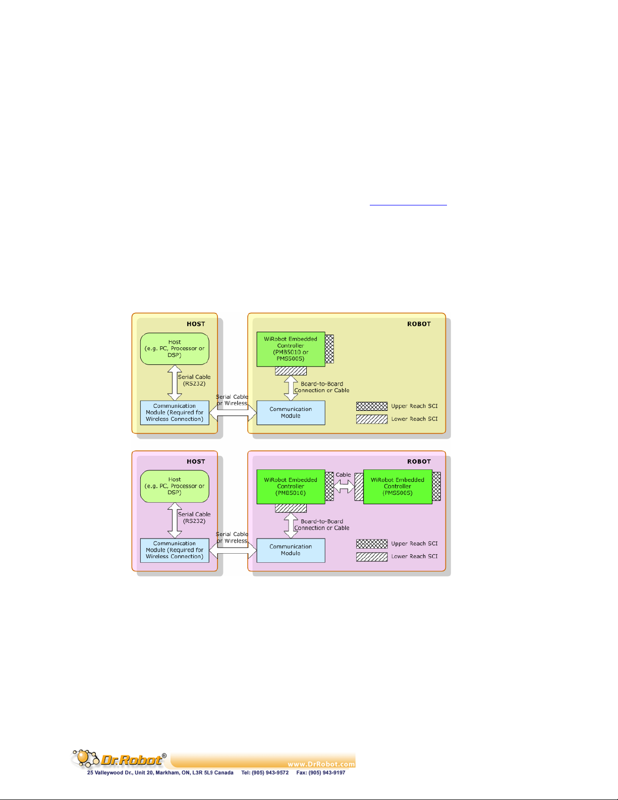
control, user can also send various control commands to the robot. A general connection architecture
of the WiRobot system is shown as follows:
)
Copyright © Dr Robot Inc. 2005
Figure II.1 WiRobot System Communication Architecture
7
Page 9
III. Software (WiRobot SDK) Installation
III.1 System Requirements
The PC requirements in using the WiRobot system are:
. PIII 550MHz or faster CPU
. 64 MB RAM or more
. 20 MB hard disk free space
. Microsoft Windows 2000 or XP operating system
As well as, Microsoft Visual VB or VC++ 6.0 (with Service Pack 5) is required for users to develop their
own applications.
III.2 WiRobot System Installation
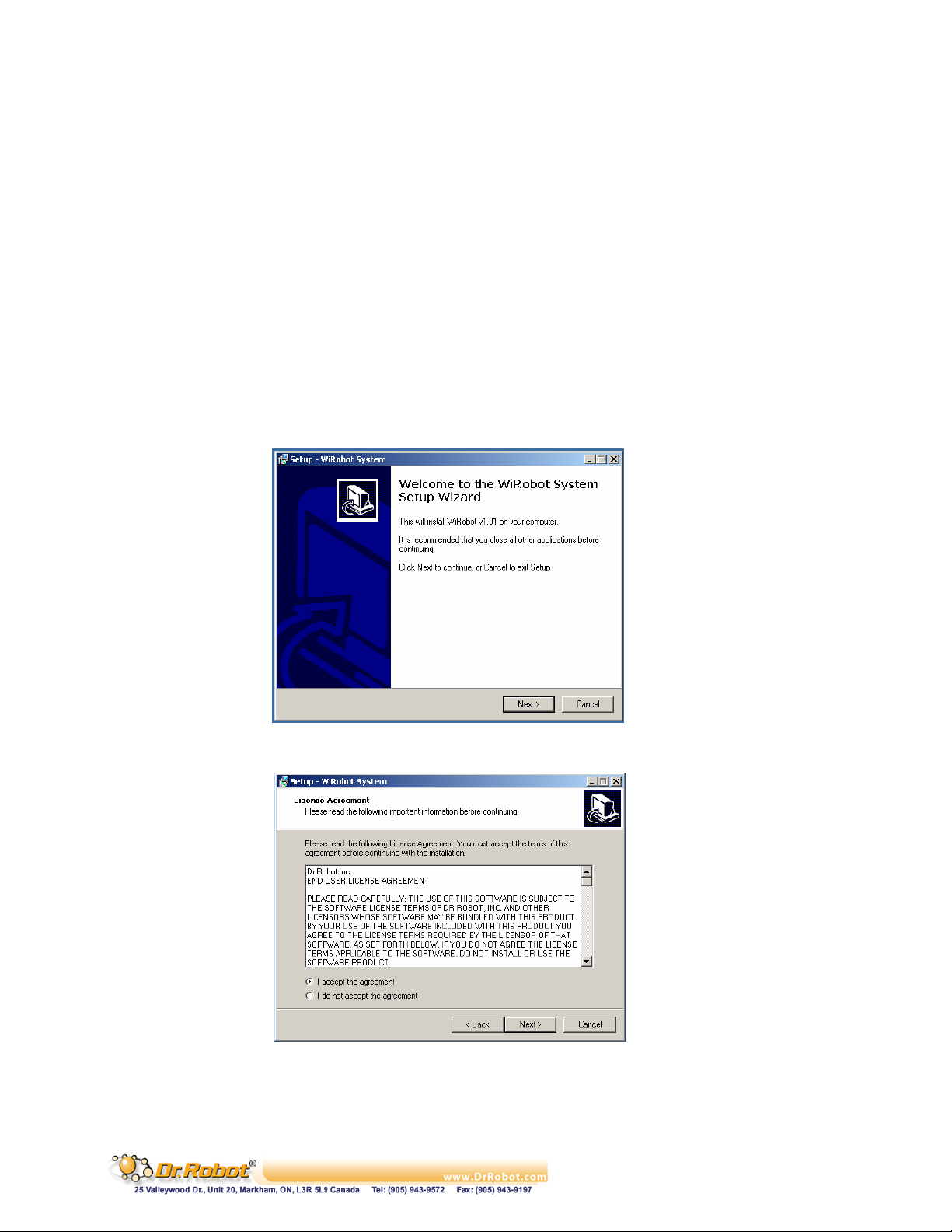
Insert the WiRobot System CD into the CD ROM and the auto run menu will guide you through the
installation process.
Copyright © Dr Robot Inc. 2005
Figure III.1 WiRobot Installation Step 1
Figure III.2 WiRobot Installation Step 2
8
Page 10
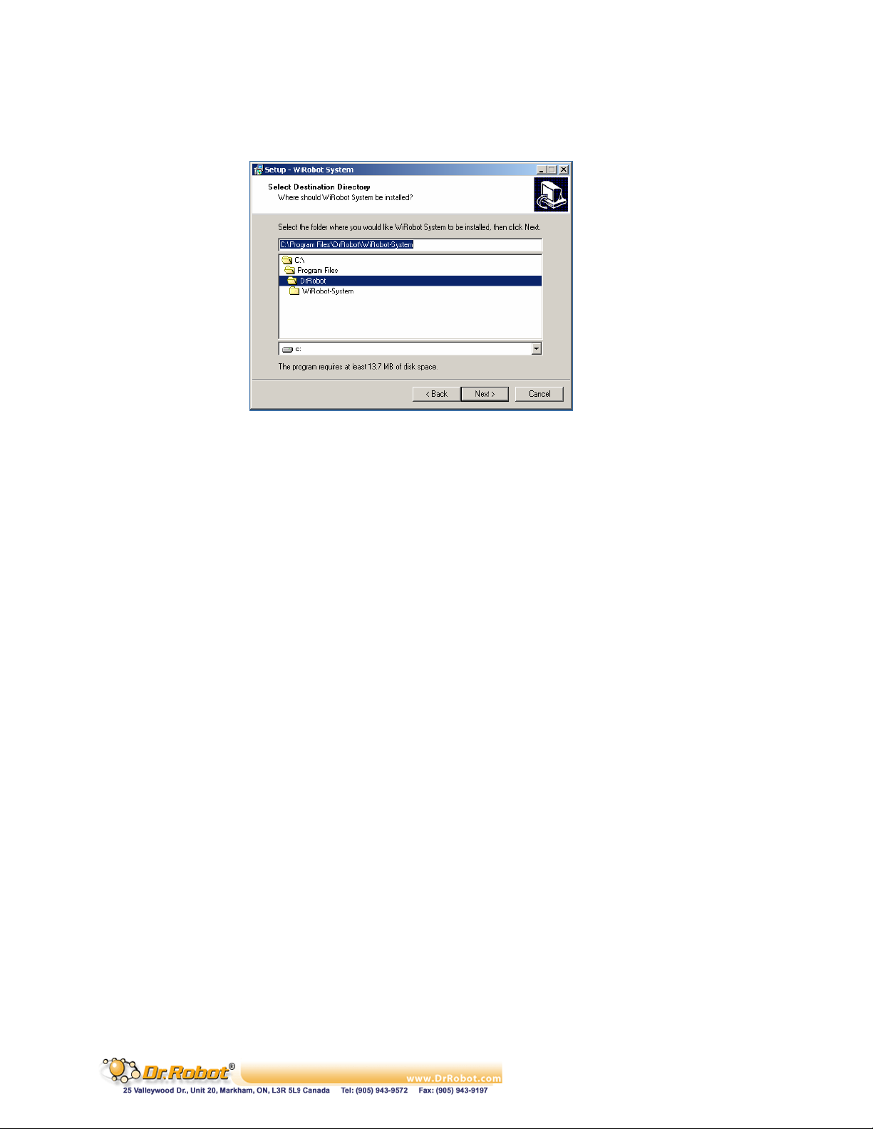
By default, all these components will be installed under the directory “C:\Program
Files\DrRobot\WiRobot-System” unless user specifies another location during the installation.
Figure III.3 WiRobot Installation Step 3
IV. Connecting to WiRobot System
IV.1 WiFi Wireless Connecting
IV.1.1 Configuration your 802.11b (or 802.11b compatible) wireless access point/router
Configuration your 802.11b (or 802.11b compatible) wireless access point/router with following
default settings:
SSID: dri
SSID BROADCAST: Enable
AUTHENTICATION: SHARED KEY
WEP 128 bit key: 112233445566778899AABBCCDD
Router IP: 192.168.0.200
If you prefer to change the router setting, such as SSID, router IP and/or key, you have to configure
the WiFi module (see Chapter IV, session IV. WFS802b WiFi 802.11 Serial Module with Antenna) on
the robot to match your changed settings.
Copyright © Dr Robot Inc. 2005
9
Page 11
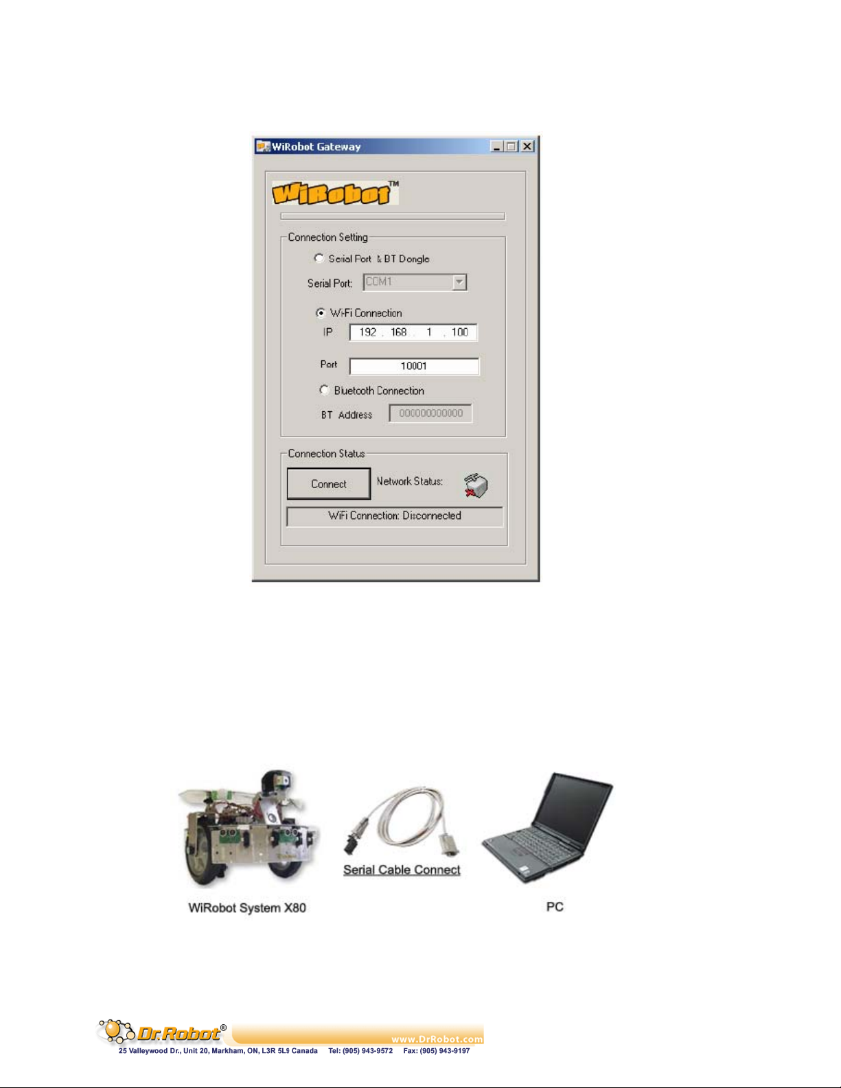
IV.1.2 Run the WiRobot Gateway
Figure IV.2 WiFi Gateway
Check the WiFi Connection and input the IP of the robot which you want to connect, and input the
Port with 10001, and then click the Connect button. You can find the robot IP under the robot.
IV.2 Serial Cable Connecting
The user can also connect the WiRobot system to a PC through a null modem cable (RS232 Crossover Serial Cable) as follows:
Figure IV.3 WiRobot System Setup without Wireless Connection
IV.2.1 Connecting the cable and module
Copyright © Dr Robot Inc. 2005
10
Page 12
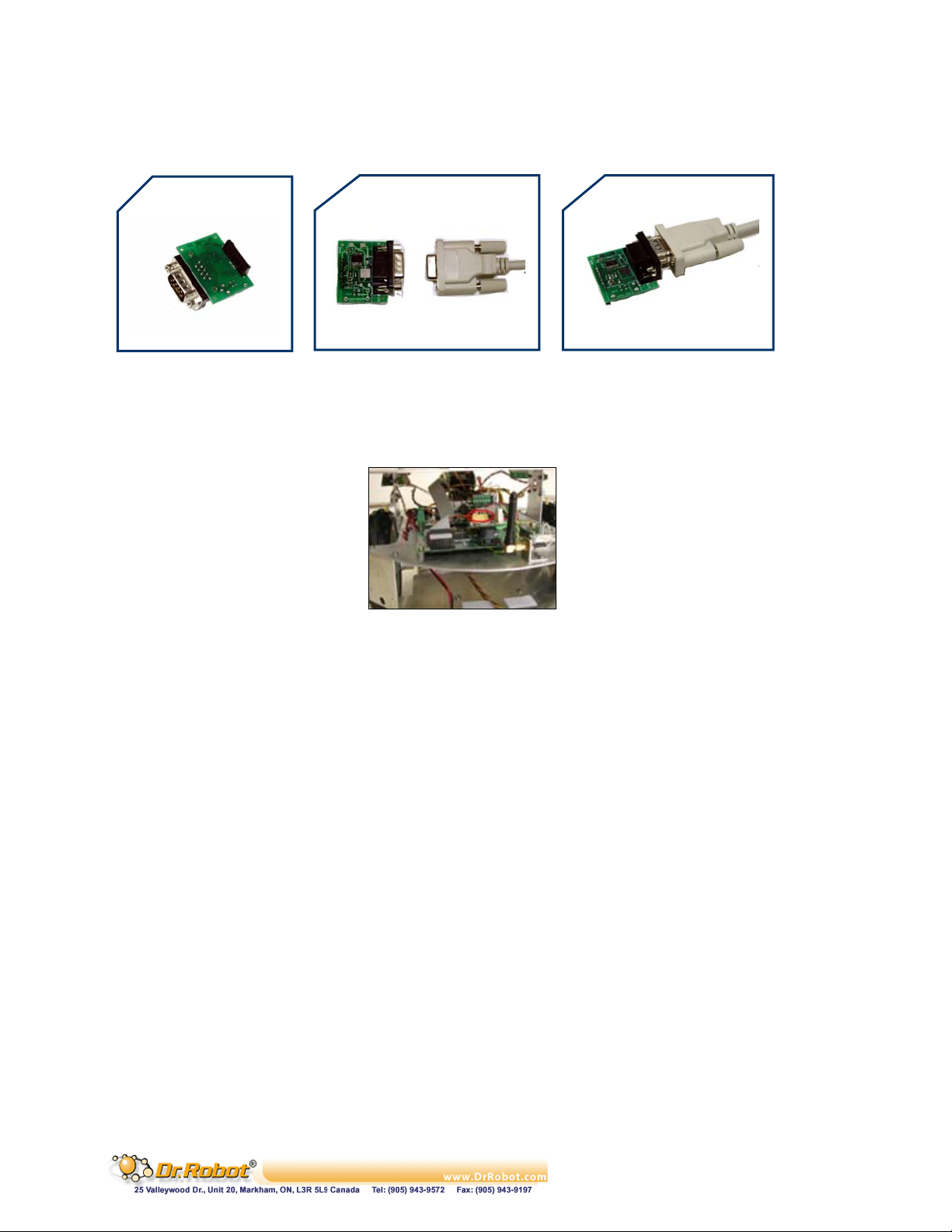
. Connect Serial cable, make sure the serial cable is connected to the COM1 socket of your PC
at one end, and the other end should be connected to the RS232 interface module.
1.
2.
3.
RS232
Figure IV.4 Connection of RS232 with Serial Cable
. Unplug the serial WIFI (or Bluetooth) wireless module which had already plugged in the lower
socket board PMB5010 of the robot.
Figure IV.5 Upper reach SCI0 of Lower Socket Board PMB5010
. Then plug the RS232 interface module in Upper Reach SCI0 on the PMB5010 which is the
lower socket board of the robot. (Picture available in the PMB5010 Multimedia Controller
User Manual, Page 94)
IV.2.2 Turn on the robot
Check the LED lights on the socket board, and find out if they are flashing on the socket board. There
should be 2 LED lights keep flashing fast on the upper board PMS5005 in the right rear corner of the
robot and 1 LED light keep flashing on the lower board in the right front corner of the robot. If these 3
LED lights are flashing, the robot is started completely.
IV.2.3 Run the WiRobot Gateway
. Select COM1 and Serial Cable
. Click the "Connect" button when you are sure that the robot is completely started.
. Wait 1 to 3 seconds, the WiRobot Gateway will minimize automatically when connected.
. If it is not connected, close the WiRobot Gateway and turn off the robot try it again 10
seconds later.
Copyright © Dr Robot Inc. 2005
11
Page 13
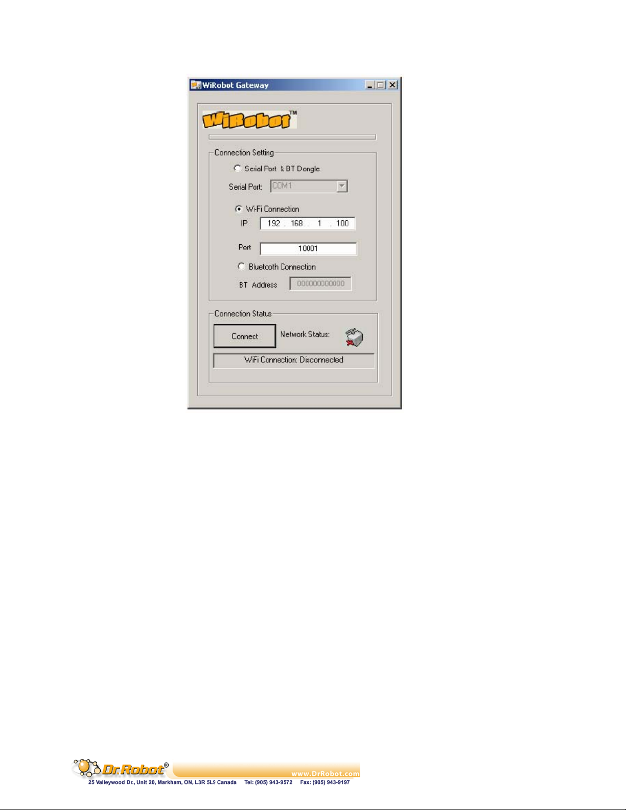
Figure IV.6 GUI of WiRobot Gateway on PC
The “WiRobot Gateway” will provide connection status information between the PC and the robot.
This program is required to keep running as long as the user wants to access and control the robot
through the sample applications or their custom programs. Robot data acquisitions including human
sensor, ultrasonic sensor, Infrared distance sensor, tilting sensor, potentiometer, color CMOS image
sensor, microphone, and etc. and motion control can be done by making function calls offered by the
“WiRobot SDK ActiveX Module”. Details of this ActiveX control component can be found in the
Chapter III. WiRobot SDK API Reference.
After the connection is established between the robot and the PC, user can start to use the WiRobot
system by running the sample applications offered in the WiRobot software package.
V. Building PC Applications Using SDK
This section will discuss how to program user’s applications. Several sample applications with source
code are provided to help user kick start in using the WiRobot system. All these source code will be
stored in the “SampleApps” folder under the WiRobot SDK installation location.
V.1 Using WiRobot SDK Component ActiveX Control
When user starts to write an application, he/she first adds the WiRobot SDK Component in your VB or
VC++ project. The ActiveX object is installed during the installation process and the following is a step
to step guideline showing how to incorporate the ActiveX Control into a VB 6.0 project:
. Create a new VB project
Copyright © Dr Robot Inc. 2005
12
Page 14
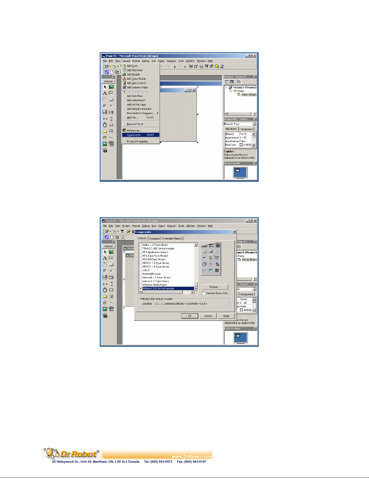
. Click “Project” in the menu and choose the “Components”
Figure V.1 Using ActiveX module under VB Step 1
. Uncheck the “Selected Items Only” box to show all components, choose the “WiRobot SDK
ActiveX Module” and click “OK”
Figure V.2 Using ActiveX module under VB Step 2
. A new icon on the left menu bar will appear and user can simply drag and drop this icon to the
Project’s Form and start using the APIs offered by this ActiveX control. By default the
variable name of this component is “WiRobotSDK1”.
Copyright © Dr Robot Inc. 2005
13
Page 15
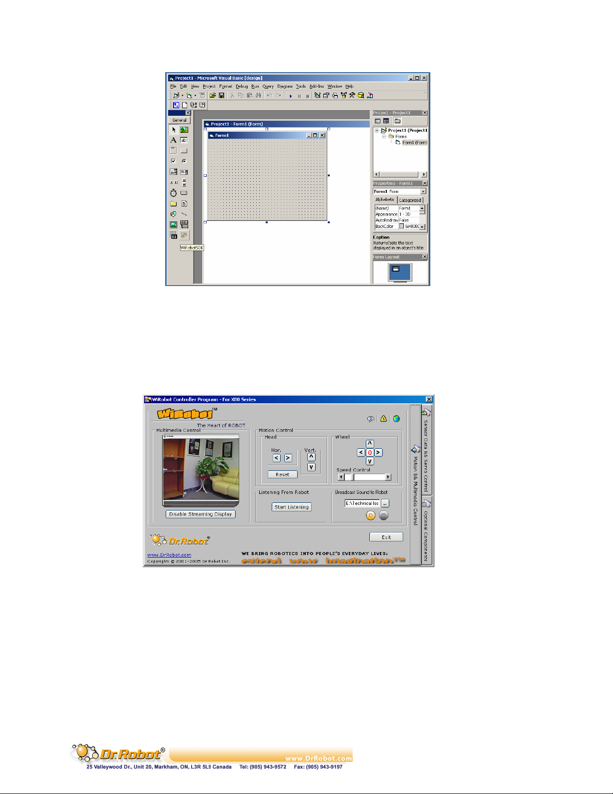
Figure V.3 Using ActiveX module under VB Step 3
V.2 Sample Application 1 – WiRobot X80 Controller (VB)
This sample application demonstrates the basic capabilities of the WiRobot X80 using Microsoft VB
with source code provided. This program can read sensor data, obtain image and audio, play wave file,
and control the robot movement with command or joystick. The GUI of this program is shown as
follows:
Copyright © Dr Robot Inc. 2005
14
Page 16
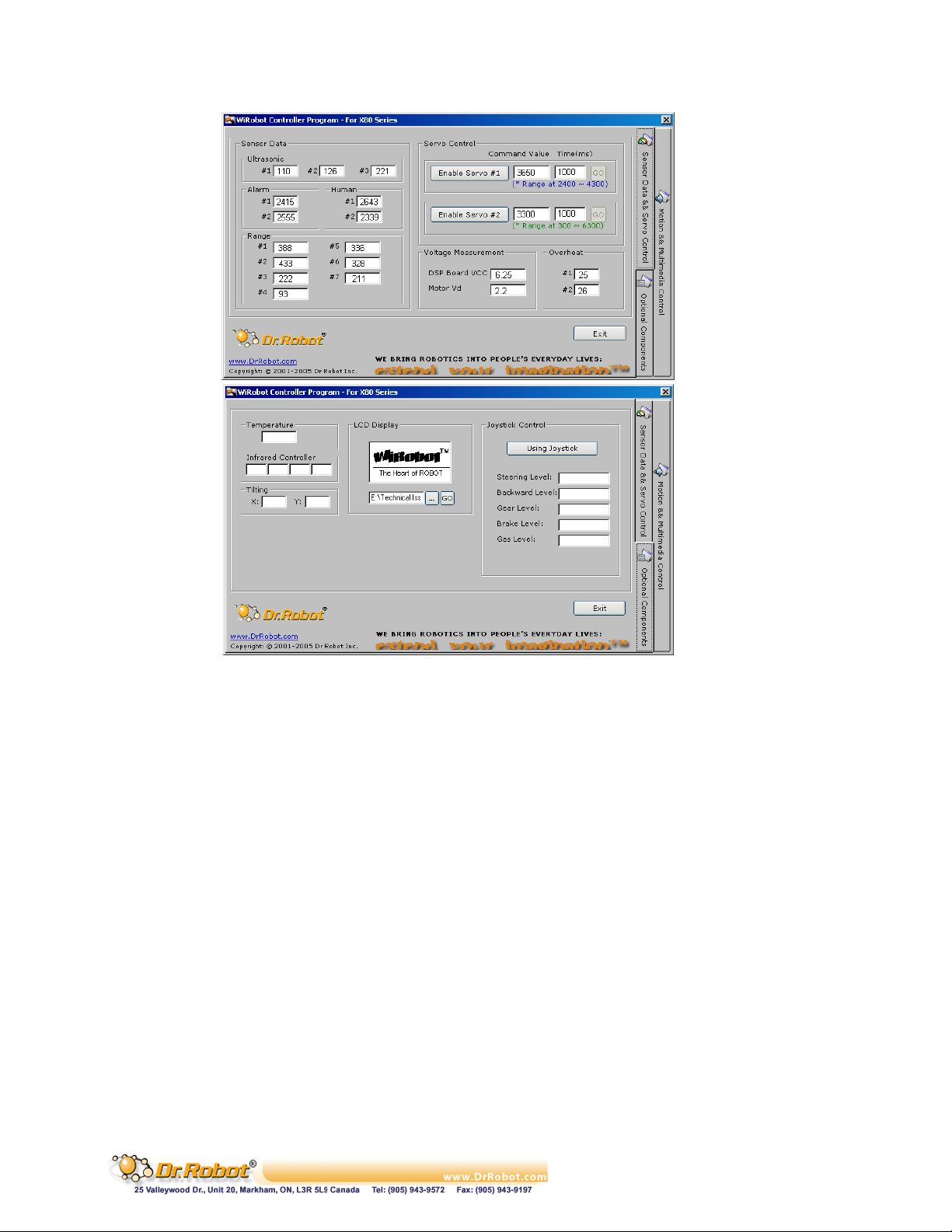
Figure V.4 GUI of the WiRobot X80 Controller (VB)
User can click the button on the interface to control the robot as long as the “WiRobot Gateway” is
connected to the robot.
The following are some functions used in this sample application for controlling the servos mounted on
the head:
WiRobotSDK1.EnableServo 0
WiRobotSDK1.ServoTimeCtr 0, 3800, 1000
The
WiRobotSDK1is the WiRobot SDK Component ActiveX control. The first line will enable the channel
0 servo. The second line will control the servo to take 1000ms to the target position of 3800.
User can also obtain and control the multimedia information of the robot simply by calling the
following functions
WiRobotSDK1.PlayAudioFile sourceFileName
The function will play the wave file to the robot with the sound file stored in the “sourceFileName”
which is in .WAV format.
Copyright © Dr Robot Inc. 2005
15
Page 17
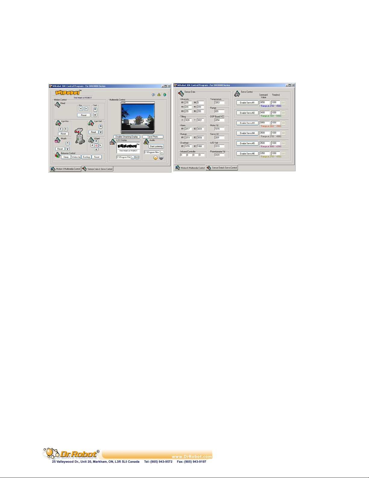
V.3 Sample Application 2 - WiRobot DRK8000 Controller (VB)
This sample application demonstrates the basic capabilities of the WiRobot DRK8000 using
Microsoft VB with source code provided. This program can read sensor data, obtain image and audio,
play wave file, set the LCD display image, and control the robot movement. The GUI of this program is
shown as follows:
Figure V.5 GUI of the WiRobot DRK8000 Controller (VB)
User can click the button on the interface to control the robot as long as the “WiRobot Gateway” is
connected to the robot.
The following are some functions used in this sample application for controlling the servos mounted on
the head:
WiRobotSDK1.EnableServo 0
WiRobotSDK1.ServoTimeCtr 0, 3800, 1000
WiRobotSDK1is the WiRobot SDK Component ActiveX control. The first line will enable the channel
The
0 servo. The second line will control the servo to take 1000ms to the target position of 3800.
User can also obtain and control the multimedia information of the robot simply by calling the
following functions
WiRobotSDK1.LcdDisplayPMS sourceFileName
WiRobotSDK1.TakePhoto
WiRobotSDK1.SavePhotoAsBMP destinationfileName
The first function will change the LCD display on the robot to the image stored in the
“sourceFileName” which is in bitmap format. The second function will request the robot to take a
picture and an “ImageEvent” will be triggered when this image is ready for pickup. The third function
will save the image to the file with “destinationfileName” in bitmap format.
V.4 Sample Application 3- WiRobot DRK6000/8000 Controller (VC++)
The second sample application demonstrates how to program a VC++ application using the WiRobot
system. The GUI of this program interface is shown as follows:
Copyright © Dr Robot Inc. 2005
16
Page 18
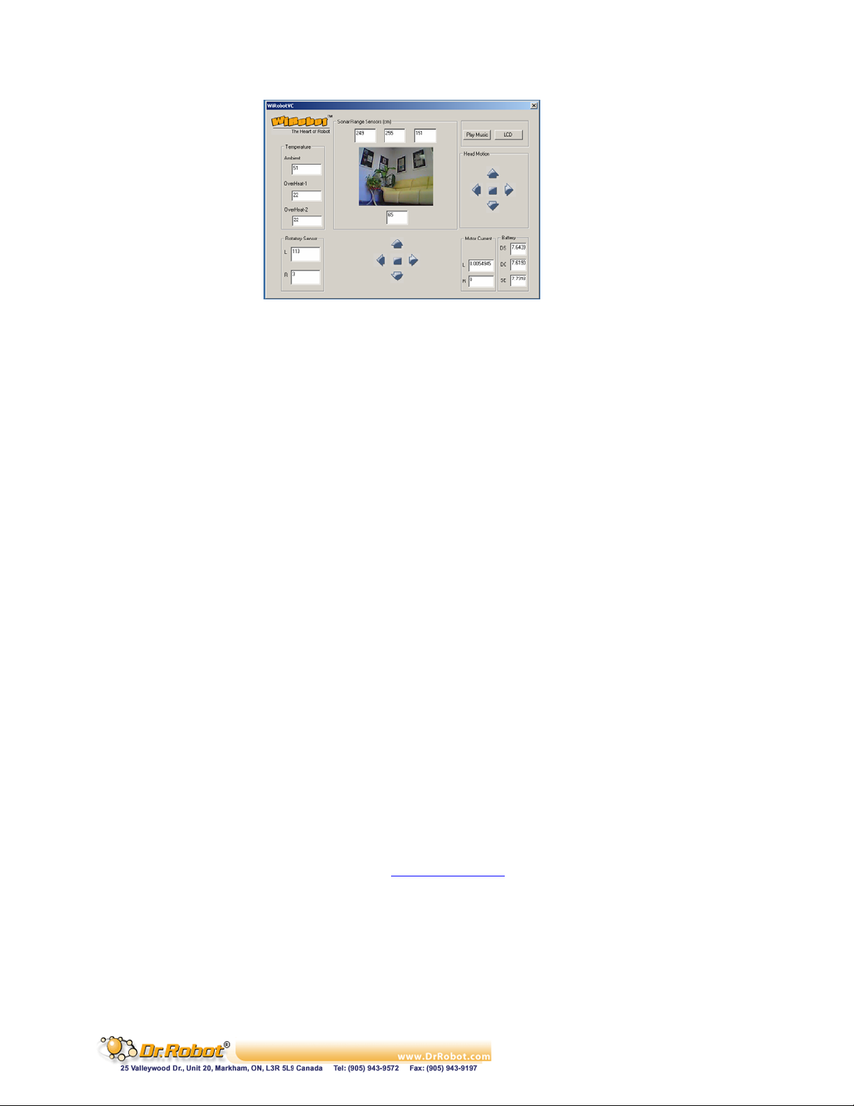
Figure V.6 GUI of the WiRobot DRK6000/8000 Controller (VC++)
To obtain an image from the robot, user can call the following function where m_ctlSDK is a member
variable of the class CWiRobotSDK imported from the “WiRobot SDK ActiveX Module”
m_ctlSDK.TakePhoto ();
To control the robot to move forward continuously, user can call the following functions
m_ctlSDK.SetDcMotorControlMode (0, 0);
m_ctlSDK.SetDcMotorControlMode (1, 0);
m_ctlSDK.DcMotorPwmTimeCtrAll (32066, 32066, -32768, -32768, -32768, -32768, 800);
To stop the robot, the following commands can be used:
m_ctlSDK.SuspendDcMotor (1);
m_ctlSDK.SuspendDcMotor (0);
For details on how to control the robot using Microsoft Visual C++, please refer to the sample C++
source code and Chapter III. WiRobot SDK API (Page 26).
V.5 Other Sample Applications
More sample applications are available in the “SampleApps” folder for reference.
VI. Miscellaneous
VI.1 System Update
Dr Robot will provide software update for both the PC software as well as the DSP software to
enhance the existing features. User can visit www.DrRobot.com
available for the existing system.
Copyright © Dr Robot Inc. 2005
to check for any new updates
17
Page 19

Chapter II. X80 System Specification
-X80 Wireless Mobile System
Copyright © Dr Robot Inc. 2005
18
Page 20

I. WiRobot X80 Overview
WiRobot is an integrated electronic and software robotic system extended from Dr Robot’s
comprehensive humanoid robot. Each WiRobot development system is designed to provide a userfriendly programming environment for hobbyists, students and researchers to develop their advanced
robot programs and applications at an affordable cost. The X80 development system includes the
respective mechanical structure, electronic modules as well as the software development kit (SDK).
The mechanical structure is already pre-built and the electronic system is setup with a Multimedia
Controller (PMB5010), a Sensing-Motion Controller (PMS5005) and various peripheral electronic
modules. The software component will be installed on a PC and is responsible to establish a wireless
connection and exchange data with the robot. User can develop their own applications in VC++ or VB
using the APIs offered in “WiRobot SDK ActiveX Module” which accesses the sensor information,
sends control command and configures the system setting.
This ready to use mobile robot platform is designed for researchers developing advanced robot
applications such as remote monitoring, telepresence and autonomous navigation/patrol.
Mechanics
The X80 is the result of extensive efforts to develop a robot that would be fast and strong,
while itself remaining lightweight and nimble. The wheel-based platform’s two 12V DC motors
each supply 300 oz.-inches of torque to the X80’s 18 cm (7 in.) wheels, yielding a top speed
in excess of 1 m/s (3.3 ft/s). Two high-resolution (1200 count per wheel cycle) quadrature
encoders mounted on each wheel provide high-precision measurement and control of wheel
movement. Weighing only 3.5 kg (7.7 lb.), the system is light, but it can carry an additional
payload of 10 kg (22 lb.).
Sensors
X80 offers full WiFi (802.11b) wireless, multimedia, sensing and motion capabilities and
comes with a wide range of sensor, camera, and audio modules, sufficient to serve in any
variety of applications. The X80 offers broad expandability as well for projects that may
require additional sensors, even specialized modules. Powered by separate RC servo motors,
the integrated camera head can pan and tilt independently.
Architecture
The X80’s underlying technology evolved from Dr Robot’s Distributed Computation Robotic
Architecture, originally developed for Dr Robot’s Humanoid (HR) Robot. Using this approach,
high-level control of the robot is maintained by a remote or local PC/server communicating by
a secure wireless link. Low-level functionality is managed by an onboard digital signal
processor (DSP) while computationally intensive operations are performed offboard. The
result is a robot that’s lighter, draws less power, runs longer and is dramatically less expensive
than a fully bundled or self-contained system. Moreover, since primary processing resides in a
server, any hardware upgrades to the central unit are shared by all the robots it controls.
With its integrated high bandwidth (11Mbps) WiFi 802.11 wireless module, the system can
upload all sensor data (including encoder sensor readings) to a PC or server at rates in excess
of 10Hz. Similarly, streaming audio (8Hz x 8bits) and video (up to 4 fps) either for direct
monitoring or for processing by high-level AI schemes is a snap. Commands and instructions
sent to the X80 via the same wireless link also pass at rates exceeding 10Hz, providing realtime control and access.
Copyright © Dr Robot Inc. 2005
19
Page 21

The X80 includes all WiRobot development software components (for MS Windows 2000
and up), enabling easy access to all data and information in a standard Microsoft Windows
programming environment (e.g., MS VB and VC++). Under the approach of using a separate
PC for high-level control, there are no longer onboard restrictions on a mobile system’s
processing power, memory and storage.
With the X80 system, researchers can develop a specialized intelligent robotic assistant,
security robot or simply use it as a platform for a variety of projects built around applications
such as human-machine interaction, mobile system navigation, robot behavior, image
processing, object recognition, voice recognition, teleoperation, remote sensing, map building
and localization etc.
The X80 system is fully integrated and each robot is fully assembled and tested prior to
shipping so that it arrives ready for use.
Mechanical and Control Highlights
. Two 12V motors with over 300oz.-inch torque each
. 7 inch driving wheel
. Max speed of 1 m/sec
. Dimensions:
o 38.0 cm (15.0 inch) diameter
o 25.5 cm (10.0 inch) height
. Weight: 3.5 kg
. Large top mounting deck for additional devices such as a notebook computer
. Additional carrying payload: 10 kg
. Pre-programmed fine speed and position control achieved by an integrated PMS5005
module employing two 1200 count per wheel-cycle quadrature encoders.
Electronic System Highlights
. Fully integrated WiFi (802.11b) system with dual serial communication channels (max of
912.6 Kbps per channel), supporting both UDP and TCP/IP protocol.
. Full color video and two-way audio capability. (CMOS color image module and audio module
are fully integrated.)
. Battery: 3700mAh with over 3 hours for nominal operation.
. Collision detection sensors include 3 sonar range sensors and 7 IR range sensors
. Two pyroelectric sensors for human motion detection
. Additional sensors such as supplementary sonar sensors, temperature sensors, acceleration /
tilting sensor, or customized sensors can be added.
Copyright © Dr Robot Inc. 2005
20
Page 22

Standard Electronics components and Operation Detail
WiRobot X80 Specifications
On-Board CPUs TI 120MIPS & Motorola 40MIPS 16-bit fix-point DSP
On-Board Storage 1M x 16-bit words flash, Up to 256K x 16-bit words SRAM
Degree of Freedom 2 x wheel motion, 2 x camera motion (Pan + Tilt) , up to 6 servos and 3 DC motors)
Built-in Peripheral Interface
and Modules
Wireless Operation Range >25 meter indoor
Power Supply 7.2V Ni-MH 3700mAh
Operation Time Nominal usage with 3700mAh battery
Maximum Moving Speed Approx. 1 meter per second
Additional/Optional
Peripheral Modules
:
Table I.1 WiRobot X80 Specifications
8-bit CIF (352 x 288) Color CMOS Camera Module
Audio codec and amplifier module with mic. and speakers
WiFI 802.11b wireless module
General-purpose PWM DC motor control
DC motors (up to 3)
Servo motors (up to 6)
Quadrature Encoder Inputs
Ultrasonic sensor modules (up to 6)
Human sensor module (up to 2)
Infrared range sensor input
Digital inputs
Digital outputs
>100 meter line of sight
Smart fast charger
Ambient temperature sensor modules
Tilt/acceleration sensor modules
DC motor driver module (3 DC motors)
Servo
Ultrasonic sensor module
128 x 64 graphic LCD display module
Potentiometer position feedback sensor (up to 6)
Full duplex infrared remote control and communication interface
X 1
X 1
X 1
X 6
X 2
X 2
X 2
X 3
X 2
X 7
X 8
X 8
X 1
X 1
> 3hr
X 1
X 1
X 1
X 4
X 1
X 1
X 6
X 1
Copyright © Dr Robot Inc. 2005
21
Page 23
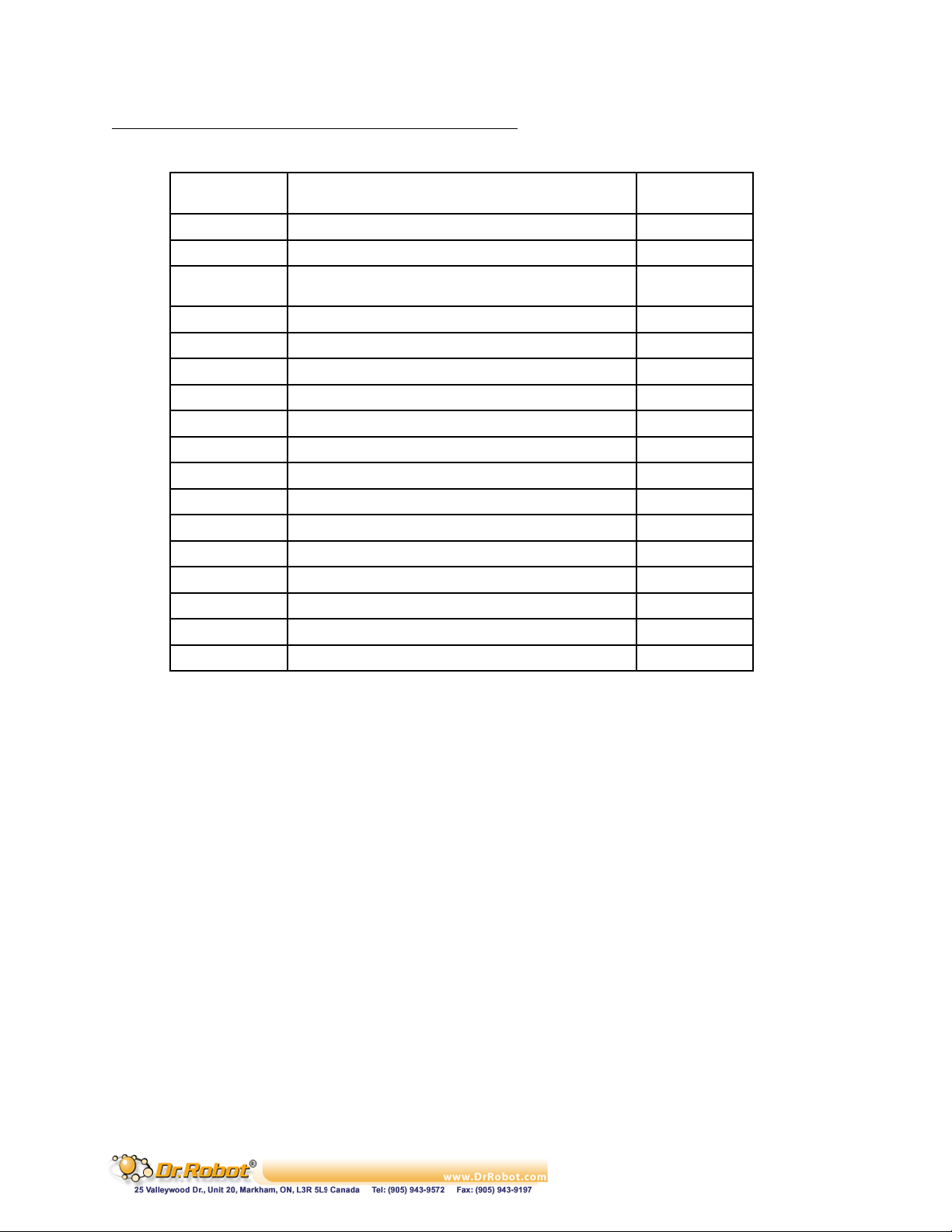
The standard WiRobot DRK series system electronic modules
Table I.2 Standard WiRobot DRK Series System Electronic Modules
Part Number Name X80
PMS5005 Robot Sensing and Motion Controller 1
PMS5010 Multimedia Controller 1
MDM5253 DC Motor Driver Module with Position and Current
Feedback
MCI3908 Color Image Module With Camera 1
DUR5200 Ultrasonic Range Sensor Module 3
DHM5150 Pyroelectric Human Motion Sensor Module 2
GP2Y0A21YK Sharp IR Distance Measuring Sensor Module 7
MCR3210 RS232 Interface Module 1
WFS802b WiFi802.11b Wireless Serial Module 1
BAS8100 8Ohm 1W Speaker 1
MAC5310 Audio Codec and Audio Power Amplifier Module 1
SAM5247 Uni-directional Electret Microphone 1
CCR2150 RS232 Cross-over Serial Cable 1
N/A Servo 2
N/A 12V DC Motor 2
BPN7240 7.2V Ni-MH 3700mAh Battery Pack 1
2300333 7.2V/9.6V NI-CD/NI-MH R/C PACK CHARGER 1
:
1
Copyright © Dr Robot Inc. 2005
22
Page 24
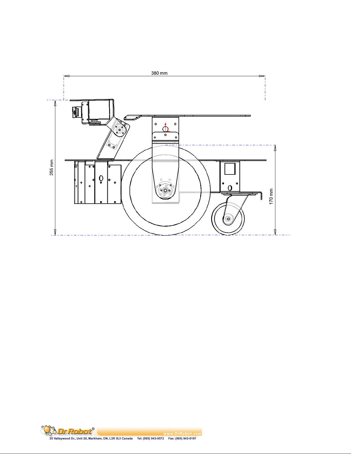
I.1 Mechanical Specification
The following diagram illustrates the mechanical structure of the WiRobot X80 system:
Figure I.1 WiRobot X80
I.2 Electrical
I.2.1 Power
The X80 is powered by a single 7.2V battery pack. This battery pack is connected to both PMS5005
and PMB5010 through a switch. User can turn on or turn off the system (both PMS5005 and
PMB5010) by pressing the switch next to the head base.
I.2.2 Communication
In the X80 system, PMS5005 and PMB5010 are connected together between PMB5010’s Lower
Reach SCI1 and PMS5005’s Upper reach SCI0. A wireless module is placed on PMB5010’s Upper
Reach SCI0 in order to communicate with a PC.
Copyright © Dr Robot Inc. 2005
23
Page 25
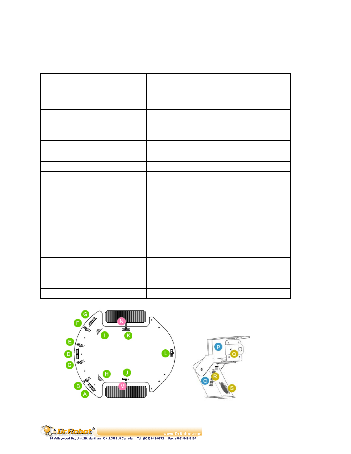
I.2.3 Electrical Modules
In this system, all electrical modules are located and connected as followed:
Table I.3 Electrical Modules Located and Connection
Electrical Module X80 Location / Setting
Ultrasonic #1
Ultrasonic #2
Ultrasonic #3
Human Sensor #1
Human Sensor #2
Infrared Range Sensor #1
Infrared Range Sensor #2
Infrared Range Sensor #3
Infrared Range Sensor #4
Infrared Range Sensor #5
Infrared Range Sensor #6
Infrared Range Sensor #7
Servo #1
Servo #2
DC Motor #1 with quadrature encoder
DC Motor #2 with quadrature encoder
Camera
Speaker
Microphone
A
○
Left front
D
○
Middle front
G
○
Right front
H
○
Left front, upper lever
I
○
Right front, upper lever
B
○
Front
C
○
Front
E
○
Front
F
○
Front
K
○
Right side
L
○
Rear
J
○
Left side
P
○
To control the left/right movement of the neck (use
channel 1)
O
○
To control the up/down movement of the neck (use
channel 2)
M
○
Left , use channel 1
N
○
Right, use channel 2
Q
○
Middle front
S
○
Middle front, under the camera
R
○
Beside the speaker
Copyright © Dr Robot Inc. 2005
Figure I.2 Electrical Modules Located
24
Page 26
Please refer to Chapter IV.I PMS5005 (Page 67) for details on how to connect different sensors, DC
motors, servos, and LCD display to the system. For camera, speaker and microphone, please refer to
Chapter IV.II PMB5010 (Page 82).
I.3 Other Specification
Table I.4 Other Specification
X80
Weight (including one battery pack) ~3.5kg
Recommended Maximum payload ~10kg
II. Miscellaneous
II.1 Battery Recharging
User can simply take out the battery at the lowest deck of the robot to recharge. It will normally take
about 20 hours to fully recharge the 3700mAh battery if slow charging is chosen. Fast charge would
take about 1-2 hours.
II.2 Sensor Location
User can change the sensor mounted on the robot to different location to suit his/her needs. As well,
user can add new sensors to the systems by making use of the available I/Os on the Sensing and
Motion Controller (PMS5005). Driver for these I/Os have been pre-programmed, data will be sent to
the PC for processing.
II.3 Known Issues
. When the power level is low, the robot’s electrical system will become unstable. User has to
monitor the power level and recharge the battery when it is low.
. The initialization of the robot (when powering on) will take about 3-10 seconds.
. Please make sure that the robot finished its initialization stage before WiRobot Gateway
software (on PC) starts to connect to the robot. This may lead to failure connection between
PC and the robot
Copyright © Dr Robot Inc. 2005
25
Page 27

Chapter III. WiRobot SDK Application Programming
Interface (API) (For MS Windows)
Copyright © Dr Robot Inc. 2005
26
Page 28

I. Convention
Data Type
int: 16 bit signed interger
UWord16: 16 bit unsigned interger
short: 16 bit signed interger
Syntax
Syntax under each API reference is based on the C/C++ calling convention. Corresponding Visual
Basic calling convention can be found in relevant VB reference book, or from the WiRobot VB code
examples.
Copyright © Dr Robot Inc. 2005
27
Page 29
II. WiRobot SDK Overview
WiRobot Software Development Kit (SDK) is a part of the WiRobot development system. Being a PCbased software framework for robotic system development, the SDK contains the facilities for
memory management, system communication and user interface, and the utilities for audio, video
input/output, sensor data acquisition and motion control. Please refer to the Chapter IV.I PMS5005,
Chapter IV.II PMB5010, or Chapter II X80 for the detailed information on the SDK architecture,
organization and system programming.
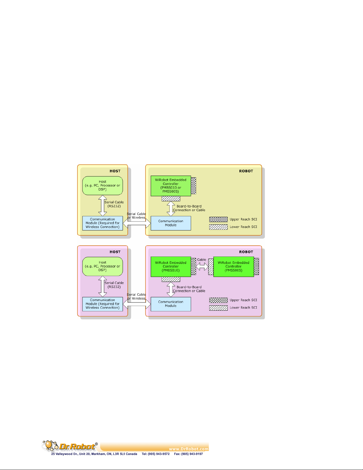
Under the WiRobot system architecture, all the controllers are connected in a chain. Programs
developed using WiRobot SDK runs on the Host as the central controller of each chain. All the
embedded controllers have at least two SCI ports for the system communications: upper-reach port
and lower-reach port, with the direction respect to the central controller. The WiRobot system
controller-level connection architecture is shown as Figure II.1.
Figure II.1 WiRobot System Architecture
The APIs described in this manual are the interface between the application-level software and the
WiRobot hardware system. Programs developed using WiRobot SDK runs on the PC sending and
receiving data to and from the WiRobot hardware via wire or wireless connection. The firmware on the
embedded controllers take care of all the low level operations of the system functional modules, such
as data acquisition, fast-loop low level motion control, image and audio capture and compression,
audio playback and wireless communication. They are transparent to the high level software system
running on the central PC controller. All the system software development can be carried on solely
under user-friendly PC system. WiRobot SDK for Windows is available for MS Visual C++ and MS
Visual Basic environment.
API exists as a MS ActiveX component, called “WiRobot SDK ActiveX Module”. User program uses
this component in VB or VC++ program to communicate with the WiRobot PMS5005 or/and
Copyright © Dr Robot Inc. 2005
28
Page 30
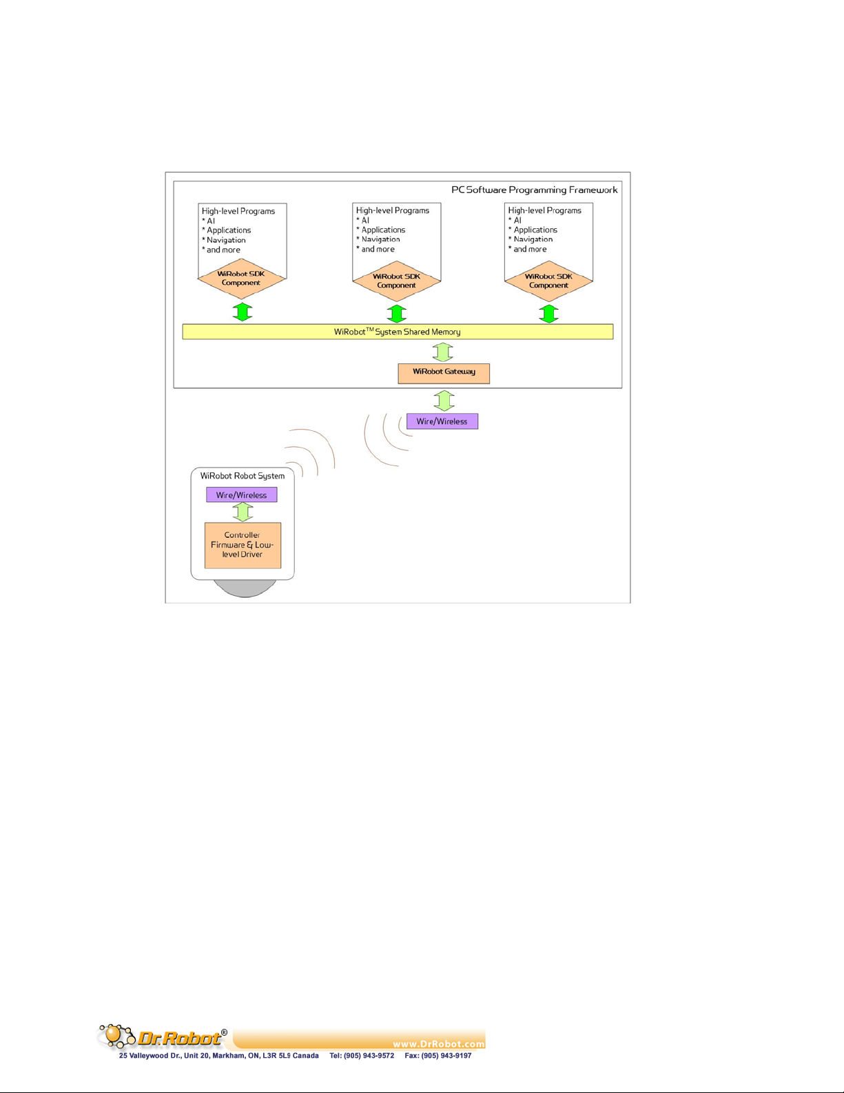
PMB5010 controllers. Data in between WiRobot hardware and the “WiRobot SDK ActiveX Module”
is managed and transferred by the supplied WiRobot Gateway Program (WiRobotGateway.exe) with
the shared memory as shown in Figure II.2.
Figure II.2 WiRobot Software Architecture
Copyright © Dr Robot Inc. 2005
29
Page 31

III. WiRobot SDK API Reference for PMS5005
WiRobot SDK APIs for PMS5005 are grouped under the categories of Sensor Peripherals, Motion
Control, Multimedia Control and Events
III.1 Sensor Peripherals
This section contains the APIs for the operations of different sensor peripherals.
III.1.1 Batch Sensor Data Updating API
Standard Sensors: Sonar, human, infrared range, tilt/acceleration, temperature, battery voltage and
infrared remote control receiver
Motor Sensors: Potentiometers, current feedback sensors and encoders.
Custom Sensors: Custom expansion A/D inputs and digital inputs.
1 void SystemMotorSensorRequest(int PacketNumber);
2 void SystemStandardSensorRequest(int PacketNumber);
3 void SystemCustomSensorRequest(int PacketNumber);
4 void SystemAllSensorRequest(int PacketNumber);
Description:
SystemMotorSensorRequest sends a request command to the WiRobot Sensing and
Motion Controller (PMS5005) in order to get the sensor data related to motor control.
SystemStandardSensorRequest sends a request command to the WiRobot Sensing and
Motion Controller (PMS5005) in order to get all the WiRobot standard sensor data.
SystemCustomSensorRequest sends a request command to the WiRobot Sensing and
Motion Controller (PMS5005) in order to get all custom-sensor data,
SystemAllSensorRequest sends a request command to the WiRobot Sensing and Motion
Controller (PMS5005) in order to get all the sensor data.
Syntax: SystemMotorSensorRequest (PacketNumber); // motor related sensors
SystemStandardSensorRequest (PacketNumber); // standard sensors
SystemCustomSensorRequest (PacketNumber); // custom sensors
SystemAllSensorRequest (PacketNumber); // all the sensors
Parameter: short PacketNumber;
The meanings of PacketNumber as follows:
.
PacketNumber = 0 Stop sending the sensor data packets
PacketNumber = -1
PacketNumber > 0
Copyright © Dr Robot Inc. 2005
Table III.1 Meanings of PacketNumber
Parameter Action Requested
Send sensor data packet continuously until being asked to
stop
Send n = PacketNumber packet(s) of sensor data and then
30
Page 32

Return value: void
Remarks:
(1) The default update rate is 20Hz. User can set up the data refresh rate according
to real system requirements.
(2) System is default to continuously sending all data when bootup.
See Also: SetSysMotorSensorPeriod, SetSysStandardSensorPeriod,
SetSysCustomSensorPeriod, SetSysAllSensorPeriod.
5 void EnableMotorSensorSending ();
6 void EnableStandardSensorSending ();
7 void EnableCustomSensorSending ();
8 void EnableAllSensorSending ();
Description:
EnableMotorSensorSending enables batch updating motor-related sensor packets.
EnableStandardSensorSending enables batch updating standard sensor packets.
EnableCustomSensorSending enables batch updating custom sensor packets.
EnableAllSensorSending enables batch updating all the sensor packets.
Syntax: EnableMotorSensorSending(); // motor related sensors
EnableStandardSensorSending (); // standard sensors
EnableCustomSensorSending (); // custom sensors
EnableAllSensorSending (); // all the sensors
Parameter: void
Return value: void
Remarks:
1. The latest request setting of the packet number and the update rate are used.
2. By default, “all sensor data sending” is enabled.
3. Please refer to the remarks under SystemMotorSensorRequest,
SystemSatndardSensorRequest, SystemCustomSensorRequest,
SystemAllSensorRequest
stop sending
9 void DisableMotorSensorSending ();
Copyright © Dr Robot Inc. 2005
31
Page 33

10 void DisableStandardSensorSending ();
11 void DisableCustomSensorSending ();
12 void DisableAllSensorSending ();
Description:
DisableMotorSensorSending disables batch updating motor-related sensor packets.
DisableStandardSensorSending disables batch updating standard sensor packets.
DisableCustomSensorSending disables batch updating custom sensor packets.
DisableAllSensorSending disables batch updating all the sensor packets.
Syntax: DisableMotorSensorSending(); // motor related sensors
DisableStandardSensorSending (); // standard sensors
DisableCustomSensorSending (); // custom sensors
DisableAllSensorSending (); // all the sensors
Parameter: void
Return value: void
See Alao: SystemMotorSensorRequest, SystemStandardSensorRequest,
SystemCustomSensorRequest, SystemAllSensorRequest.
13 void SetSysMotorSensorPeriod(short PeriodTime) ;
14 void SetSysStandardSensorPeriod(short PeriodTime);
15 void SetSysCustomSensorPeriod(short PeriodTime) ;
16 void SetSysAllSensorPeriod(short PeriodTime) ;
Description:
SetSysMotorSensorPeriod sets refresh rate of batch updating motor-related sensor
packets.
SetSysStandardSensorPeriod sets refresh rate of batch updating standard sensor
packets.
SetSysCustomSensorPeriod sets refresh rate of batch updating custom sensor packets.
SetSysAllSensorPeriod sets refresh rate of batch updating all the sensor packets.
Syntax: SetSysMotorSensorPeriod (); // motor related sensors
SetSysStandardSensorPeriod (); // standard sensors
SetSysCustomSensorPeriod (); // custom sensors
SetSysAllSensorPeriod (); // all the sensors
Parameter: short PeriodTime; /* Update period (in ms) for batch sensing
Copyright © Dr Robot Inc. 2005
32
Page 34

Return value: void
Remarks:
The default PeriodTime = 50 (ms), i.e. update rate is 20Hz. PeriodTime should be bigger
than 50 (ms), i.e. the system data fastest refresh rate is 20Hz.
See Also: SystemMotorSensorRequest, SystemStandardSensorRequest,
SystemCustomSensorRequest, SystemAllSensorRequest.
III.1.2 Range and Distance Sensors
17 short GetSensorSonar1 ();
18 short GetSensorSonar2 ();
19 short GetSensorSonar3 ();
20 short GetSensorSonar4 ();
21 short GetSensorSonar5 ();
packets to PC central controller */
22 short GetSensorSonar6 ();
23 short GetSensorSonar (short channel);
Description:
GetSonarSensorX returns the current distance value between the relevant ultrasonic
range sensor module (DUR5200) and the object in front of it. The unit is cm.
Syntax: ival = GetSensorSonar1 (); // Sonar #1
ival = GetSensorSonar2 (); // Sonar #2
ival = GetSensorSonar3 (); // Sonar #3
ival = GetSensorSonar4 (); // Sonar #4
ival = GetSensorSonar5 (); // Sonar #5
ival = GetSensorSonar6 (); // Sonar #6
ival = GetSensorSonar (short channel); // Sonar #1, 2, 3, 4, 5, or 6
Parameter: void
short channel; // 0, 1, 2, 3, 4, or 5 for Sonar #1, 2, 3, 4, 5, 6
Return value: short ival;
Return data interpretation:
Table III.2 Meanings of PacketNumber
Copyright © Dr Robot Inc. 2005
Return Value Distance to Object
4 0 to 4 cm
4 to 254 4 to 254 cm
33
Page 35
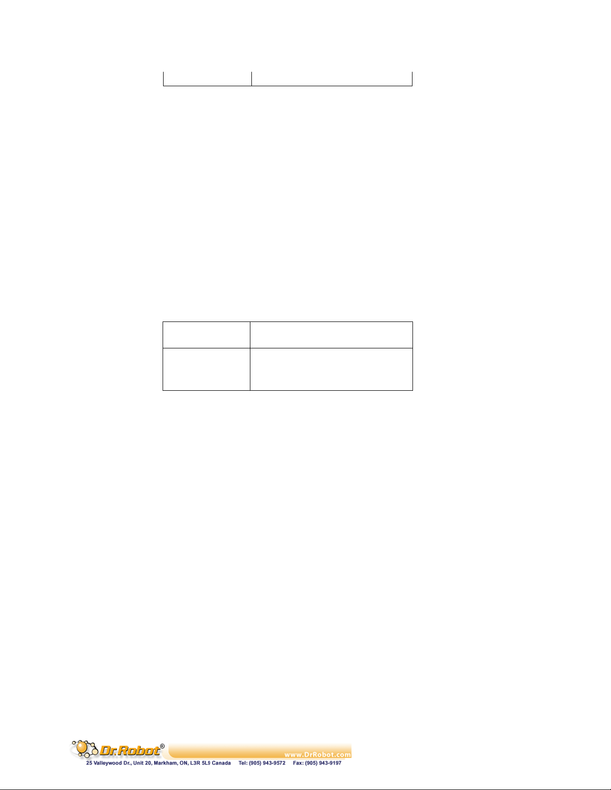
255 255 cm or longer
24 short GetSensorIRRange ();
Description:
GetSensorIRRange returns the current distance measurement value between the infrared
range sensor and the object in front of it.
Syntax: ival = GetSensorIRRange ();
Parameter: void
Return value: short ival;
Return data interpretation when using Sharp GP2Y0A21YK:
Return Value Distance to Object
<=585 80 cm or longer
585 to 3446 80 to 8 cm
>=3446 0 to 8 cm
Remarks:
The relationship between the return data and the distance is not linear. Please refer to the
sensor’s datasheet for distance-voltage curve. The data returned is the raw data of the
analog to digital converter. The output voltage of the sensor can be calculated from the
following equation:
Sensor output voltage = (ival) * 3.0 / 4095 (V)
(e.g. Sharp GP2Y0A21YK
“http://sharp-world.com/products/device/lineup/data/pdf/datasheet/gp2y0a_d_e.pdf”)
Table III.3 Return data interpretation
III.1.3 Human Sensors
25 short GetSensorHumanAlarm1 ();
26 short GetSensorHumanAlarm2 ();
Description:
GetSensorHumanAlarm returns the current human alarm data from DHM5150 Human
Motion Sensor Module. Please refer to the Chapter IV.VIII DHM5150 (Page 106) for
detailed information.
Copyright © Dr Robot Inc. 2005
34
Page 36

Syntax: ival = GetSensorHumanAlarm1(); //1
ival = GetSensorHumanAlarm2 (); // 2
Parameter: void
Return value: short ival;
Return data interpretation:
The return data is the raw value of the analog to digital converter indicating the amplified (x
5 times) output voltage of the sensor device. The data range is between 0 and 4095. When
there is no human present, the module output voltage is about 1.5 V and return value is
about 2047.
Remarks:
To detect human presence, the application should compare the difference of two samples
(to detect the change from “absence” to “presence”), and also compare the sample data to a
user defined threshold (to determine whether to report an alarm or not). The threshold
determines the sensitivity of sensor. The higher the threshold is the lower the sensitivity
will be.
27 short GetSensorHumanMotion1 ();
st
human alarm
nd
human alarm
28 short GetSensorHumanMotion2 ();
Description:
GetSensorHumanMotion returns the current human motion value from DHM5150 Human
Motion Sensor Module. Please refer to the Chapter IV.VIII DHM5150 (Page 106) for
detailed information.
Syntax: ival = GetSensorHumanMotion1 (); // Human direction data #1
ival = GetSensorHumanMotion2 (); // Human direction data #2
Parameter: void
Return value: short ival;
Return data interpretation:
The return data is the un-amplified raw value of the analog to digital converter indicating
the output voltage of the sensor device. The data range is between 0 and 4095.
Remarks:
To detect human motion direction, the application should compare the difference of two
samples of each sensor module’s output (to detect the change from “absence” to
“presence”), and then compare the sample data of the two sensor modules. For a single
source of human motion, the different patterns of the two sensor modules manifest the
directions of the motion. The relationship can be obtained from the experiments.
III.1.4 Tilt and Acceleration Sensor
Copyright © Dr Robot Inc. 2005
35
Page 37

29 short GetSensorTiltingX ();
30 short GetSensorTiltingY ();
Description:
GetSensorTiltingX, GetSensorTiltingY, return the current tilt angle values in the relevant
directions from DTA5102 Tilting and Acceleration Sensor Module.
Syntax: ival = GetSensorTiltingX (); // X direction
ival = GetSensorTiltingY (); // Y direction
Parameter: void
Return value: short ival;
Return data interpretation:
Tilting Angle = ArcSin ((ival- ZeroGValue) / abs(90DegreeGValue-ZeroGValue));
Remarks:
Where 90DegreeGValue and ZeroGValue are module-specific values that can be measured
by experiment:
1. Place the sensor level, so that the gravity vector is perpendicular to the measured
sensor axis
2. Take the measurement and this value would be the ZeroGValue
3. Rotate the sensor so that the gravity vector is parallel with the measured axis
4. Take the measurement and this value would be the 90DegreeGValue
5. Repeat this step for the other direction
Typical value of ZeroGValue is about 2048 and abs(90DegreeGValue-ZeroGValue) is
about 1250.
III.1.5 Temperature Sensors
31 short GetSensorOverheatAD1 ();
32 short GetSensorOverheatAD2 ();
Description:
GetSensorOverheatADX returns the current air temperature values near the relevant DC
motor drive modules (MDM5253), which could be used for monitoring whether the motor
drivers are overheating or not. This situation usually occurs if the motor currents are kept
high (but still lower than the current limit of the motor driver module) for significant amount
of time, which may result from some unfavorable inner or external system conditions and is
not recommended for regular system operations.
Syntax: ival = GetSensorOverheatAD1(); //1
Copyright © Dr Robot Inc. 2005
st
overheating sensor
36
Page 38

ival = GetSensorOverheatAD2(); //2
Parameter: void
Return value: short ival;
Return data interpretation:
The return data is the raw value of the analog to digital converter indicating the output
voltage of the sensor. The data range of the return value is between 0 and 4095. The
output voltage of the sensor can be calculated from the following equation:
Temperature (˚C) = 100- (ival – 980) / 11.6
33 short GetSensorTemperature ();
Description:
GetSensorTemperature returns the current temperature value from DAT5280 Ambient
Temperature Sensor Module.
Syntax: ival = GetSensorTemperature ();
Parameter: void
Return value: short ival;
Return data interpretation:
Temperature (˚C) = (ival – 1256) / 34.8
nd
overheating sensor
III.1.6 Infrared Remote Control Handling
34 short GetSensorIRCode1();
35 short GetSensorIRCode2();
36 short GetSensorIRCode3();
37 short GetSensorIRCode4();
Description:
GetSensorIRCodeX returns the four parts of a two-16-bit-code infrared remote control
command captured by the Sensing and Motion Controller (PMS5005) through the Infrared
Remote Controller Module (MIR5500).
Syntax: ival = GetSensorIRCode1 (); // the first code
ival = GetSensorIRCode2 (); // the second code
ival = GetSensorIRCode3 (); // the third code
Copyright © Dr Robot Inc. 2005
37
Page 39

ival = GetSensorIRCode4 (); // the fourth code
Parameter: void
Return value: short ival
Return data interpretation:
The recovered infrared remote control command (4 bytes code) is as follows:
Key Code: [the third byte] [the second byte] [the first byte]
Repeat Code: [the fourth byte]
where the repeat code would be 255 if button is pressed continuously.
38 void SetInfraredControlOutput (UWord16 LowWord, UWord16 HighWord);
Description:
SetInfraredControlOutput sends two 16-bit words infrared communication output data to
the Sensing and Motion Controller (PMS5005). The PMS5005 will then send the data out
through the infrared Remote Controller Module (MIR5500). In the case of being used for
infrared remote control, the output data serves as the remote control command.
Syntax: SetInfraredControlOutput (LowWord, HighWord);
st
Parameter: UWord16 LowWord; // 1
UWord16 HighWord; // 2
word
nd
word
Return value: void
Remarks:
1. In infrared communication application, the data format and the interpretation can
be defined by the user at the application level.
2. In infrared remote control application, the control command should be compatible
to the device to which the command is sent.
3. This API function is under development and will be available shortly.
III.1.7 Battery Voltage Monitors
39 short GetSensorBatteryAD1 ();
40 short GetSensorBatteryAD2 ();
41 short GetSensorBatteryAD3 ();
Description:
Copyright © Dr Robot Inc. 2005
38
Page 40

GetSensorBatteryADX returns the current value of the relevant power supply voltage if
the battery voltage monitor is enabled (default), or returns the relevant custom A/D inputs,
if the custom A/D input is enabled which is configured by the jumpers on PMS5005. Please
refer to Chapter IV.I PMS5005 Robot Sensing and Motion Controller (Page 67) for
detailed information on hardware setting.
Syntax: ival = GetSensorBatteryAD1(); /* for battery of DSP circuits,
or custom A/D channel #1 */
ival = GetSensorBatteryAD2(); /* for battery of DC motors,
or custom A/D channel #2 */
ival = GetSensorBatteryAD3(); /* battery for servo motors,
or custom A/D channel #3 */
Parameter: void
Return value: short ival;
Return data interpretation:
The return data is the raw value of the analog to digital converter indicating the output
voltage of the monitor. The data range is between 0 and 4095.
When monitoring the voltage of the power supply, following equations can be used to
calculate the real voltage values.
(1) Power supply voltage of DSP circuits = (ival / 4095) * 9 (V)
(2) Power supply voltage of DC motors = (ival / 4095) * 24 (V)
(3) Power supply voltage of servo motors = (ival / 4095) * 9 (V)
42 short GetSensorRefVoltage ();
43 short GetSensorPotVoltage ();
Description:
GetSensorRefVoltage returns the current value of the reference voltage of the A/D
converter of the controller DSP.
GetSensorPotVoltage returns the current value of the power supply voltage of the
potentiometer position sensors.
Syntax: ival = GetSensorRefVoltage ();
ival = GetSensorPotVoltage ();
Parameter: void
Return value: short ival;
Return data interpretation:
Copyright © Dr Robot Inc. 2005
39
Page 41

The return data is the raw value of the analog to digital converter indicating the output
voltage of the monitor. The data range is between 0 and 4095. The following equation can
be used to calculate the real voltage values.
Voltage = (ival / 4095) * 6 (V)
III.1.8 Potentiometer Position Sensors
44 short GetSensorPot1 ();
45 short GetSensorPot2 ();
46 short GetSensorPot3 ();
47 short GetSensorPot4 ();
48 short GetSensorPot5 ();
49 short GetSensorPot6 ();
50 short GetSensorPot (short channel);
Description:
GetSensorPotX returns the current value of the relevant potentiometer position sensors.
GetSensorPot (short channel) returns the current value of the specified potentiometer
position sensor.
Syntax: ival = GetSensorPot1 (); // Potentiometer sensor #1
ival = GetSensorPot2 (); // Potentiometer sensor #2
ival = GetSensorPot3 (); // Potentiometer sensor #3
ival = GetSensorPot4 (); // Potentiometer sensor #4
ival = GetSensorPot5 (); // Potentiometer sensor #5
ival = GetSensorPot6 (); // Potentiometer sensor #6
ival = GetSensorPot (channel); /* Potentiometer sensor
Parameter: void // for GetSensorPotX
short channel; /* 0, 1, 2, 3, 4, or 5 for Potentiometer #
Return value: short ival;
Return data interpretation and Remark:
1. The return data is the raw value of the analog to digital converter indicating the output
voltage of the sensor. The data range is between 0 and 4095. The angular position can
be calculated as follows, with the 180˚ position defined at sensor’s physical middle
position. Single sensor or dual sensor can be used for rotation measurement.
#1, 2, 3, 4, 5, or 6 */
1, 2, 3, 4, 5, 6 */
Copyright © Dr Robot Inc. 2005
40
Page 42

2. Single sensor is mainly used for the control of robot joint with limited rotation range.
The effective mechanical rotation range is 14˚ to 346˚, corresponding to the effective
electrical rotation range 0˚ to 332˚.
Angle position (˚) = (ival - 2048)/4095*333 + 180
3. Dual-sensor configuration is mainly used for continuous rotating joint control (such as
wheels). The effective rotation range is 0˚ to 360˚. Dual sensor configuration is only
available for channel 0 and 1. By connecting two potentiometers to potentiometer
channel 0 and channel 5, and specify the sensor type with command
SetDCMotorSensorUsage() to “Dual potentiometer sensor”, the channel 0 reading
will combine these two sensor readings into 0˚ to 360˚ range. For channel 1, you
should connect the two potentiometers to channel 1 and 4.
Angle position (˚) = (ival - 2214)/2214*180 + 180
See also: SetDcMotorSensorUsage().
III.1.9 Motor Current Sensors
51 short GetMotorCurrent1 ();
52 short GetMotorCurrent2 ();
53 short GetMotorCurrent3 ();
54 short GetMotorCurrent4 ();
55 short GetMotorCurrent5 ();
56 short GetMotorCurrent6 ();
57 short GetMotorCurrent (short channel);
Description:
GetMotorCurrentX returns the sampling value of motor current sensor.
Syntax: ival = GetMotorCurrent1 (); // Current sensor #1
ival = GetMotorCurrent2 (); // Current sensor #2
ival = GetMotorCurrent3 (); // Current sensor #3
ival = GetMotorCurrent4 (); // Current sensor #4
ival = GetMotorCurrent5 (); // Current sensor #5
ival = GetMotorCurrent6 (); // Current sensor #6
ival = GetMotorCurrent (short channel); // Current sensor #1,2,3,4,5,or 6
Parameter: void // for GetMotorCurrentX
short channel; // 0,1,2,3,4,5 for current sensor #1,2,3,4,5,or 6
Copyright © Dr Robot Inc. 2005
41
Page 43

Return value: short ival;
Return data interpretation:
The return data is the raw value of the analog to digital converter indicating the motor
current. The data range is between 0 and 4095. The real current can be calculated with the
following formula:
Motor Current (A) = (ival * 3 *375 / 200 /4095) = ival / 728
III.1.10 Encoder
58 short GetEncoderDir1();
59 short GetEncoderDir2();
60 short GetEncoderPulse1();
61 short GetEncoderPulse2();
62 short GetEncoderSpeed1();
63 short GetEncoderSpeed2();
Description:
GetEncoderDirX returns +1, 0 or -1 to indicate the direction of rotation.
GetEncoderPulseX returns the current pulse counter to indicate the position of rotation.
GetEncoderSpeedX returns the current speed of rotation.
Syntax: ival = GetEncoderDir1(); // direction of channel #1
ival = GetEncoderDir2(); // direction of channel #2
ival = GetEncoderPulse1(); // pulse counter of channel #1
ival = GetEncoderPulse2(); // pulse counter of channel #2
ival = GetEncoderSpeed1(); // speed of channel #1
ival = GetEncoderSpeed2(); // speed of channel #2
Parameter: void
Return value: short ival;
Return data interpretation:
(1) GetEncoderDirX returns -1, 0 or 1. 1 stands for positive direction, -1 stands for negative
direction, and 0 stands for no movement.
(2) GetEncoderPulseX returns pulse counter. It is an integral value to rotation with range
of 0 ~ 32767 in cycles.
(3) GetEncoderSpeedX returns the rotation speed. The unit is defined as pulse change
within 1 second. And it is the absolute value.
See also: SetDcMotorSensorUsage().
Copyright © Dr Robot Inc. 2005
42
Page 44

III.1.11 Custom Analog and Digital Inputs and Outputs
64 short GetCustomAD1();
65 short GetCustomAD2();
66 short GetCustomAD3();
67 short GetCustomAD4();
68 short GetCustomAD5();
69 short GetCustomAD6();
70 short GetCustomAD7();
71 short GetCustomAD8();
72 short GetCustomAD (short channel);
Description:
GetCustomADX returns the sampling value of the custom analog to digital input signals. By
default, custom AD1 - AD3 are used as the inputs of power supply voltage monitors for DSP
circuits, DC motors and servo motors. User can change this setting by configuring the
jumpers on PMS5005. Please refer to Chapter IV.I PMS5005 Robot Sensing and Motion
Controller (Page 67) for detailed information on hardware jumper setting.
Syntax: ival = GetCustomAD1(); /* for battery of DSP circuits,
ival = GetCustomAD2 (); /* for battery of DC motors,
ival = GetCustomAD3(); /* battery for servo motors,
ival = GetCustomAD4(); // custom A/D channel #4
ival = GetCustomAD5(); // custom A/D channel #5
ival = GetCustomAD6(); // custom A/D channel #6
ival = GetCustomAD7(); // custom A/D channel #7
ival = GetCustomAD8(); // custom A/D channel #8
ival = GetCustomAD(short channel); /* custom A/D channel #1, 2, 3, 4,
Parameter: void
short channel; /* 0, 1, 2, 3, 4, 5, 6 or 7 for
Return value: short ival;
Return data interpretation:
or custom A/D channel #1 */
or custom A/D channel #2 */
or custom A/D channel #3 */
5, 6, 7 or 8 */
channel #1, 2, 3, 4, 5, 6, 7, 8 */
Copyright © Dr Robot Inc. 2005
43
Page 45

The return data is the raw value of the analog to digital converter indicating the input
voltage levels. The data range is between 0 and 4095. The voltage levels can be calculated
from the following equation:
Sensor output voltage = (ival) * 3.0 / 4095 (V)
See also: GetSensorBatteryAD1~3
73 short GetCustomDIN();
Description:
GetCustomDIN returns a value with lower 8-bits corresponding to the 8-channel custom
digital inputs.
Syntax: ival = GetCustomDIN ();
Parameter: void
Return value: short ival;
Remarks:
Only lower 8-bit is valid and reflects the 8 input channel states. The MSB of the lower byte
represents channel #8 and LSB of the lower byte represents channel #1.
74 void SetCustomDOUT(short ival);
Description:
SetCustomDOUT sets the 8-channel custom digital outputs.
Syntax: SetCustomDOUT (ival);
Parameter: short ival;
Return value: void
Remarks:
Only the lower 8-bit is valid and can change the corresponding outputs of the 8 channels.
The MSB of the lower byte represents channel #8 and LSB of the lower byte represents
channel #1.
III.2 Motion Control
This section contains the APIs for the operations of DC motors and standard RC servo motors.
The digital controlled DC motor system is depicted as the following diagram.
Copyright © Dr Robot Inc. 2005
44
Page 46
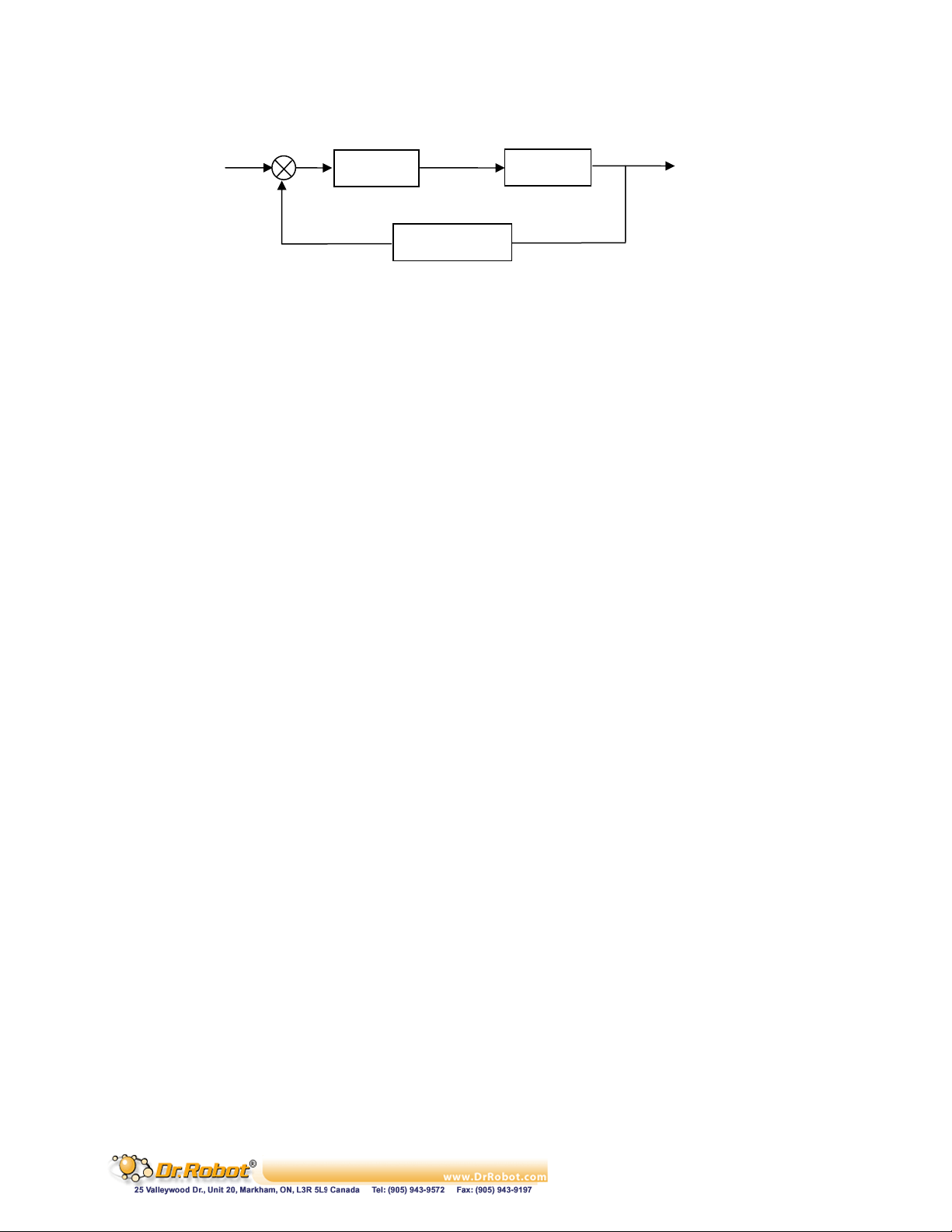
++=
G
+
E
Controller
-
F
Potentiometer
U
DC Motor
Y
Figure III.1 Digital Controlled DC Motor System
In the case of PID control, the transfer function of the PID controller looks like as:
SKSKKsEsU
/)(/)(
IDP
When using potentiometers (optical encoder and etc.) as the rotational position feedback, you have to
set the motor polarity properly using “WiRobotSDK” ActiveX control API “SetMotorPolarityX“ so
that the negative feedback is achieved. See “SetMotorPolarityX“ for detail.
The control of the standard RC servo motors is carried out by the built-in analog PID controller.
III.2.1 DC Motor Control
75 void SetMotorPolarity1 (short polarity);
76 void SetMotorPolarity2 (short polarity);
77 void SetMotorPolarity3 (short polarity);
78 void SetMotorPolarity4 (short polarity);
79 void SetMotorPolarity5 (short polarity);
80 void SetMotorPolarity6 (short polarity);
81 void SetMotorPolarity (short channel, short polarity);
Description:
SetMotorPolarityX set the motor polarity to 1 or -1 for each motor channel.
1. When the motor is running in positive direction, the potentiometer value is also
increasing; motor polarity should be set to 1 which is default.
2. When the motor is running in positive direction, the potentiometer value is decreasing,
motor polarity should be set to -1 or change the sensor mounting so that the
potentiometer value increases.
Syntax: ival = SetMotorPolarity1 (short polarity); // Motor #1
ival = SetMotorPolarity2 (short polarity); // Motor #2
ival = SetMotorPolarity3 (short polarity); // Motor #3
ival = SetMotorPolarity4 (short polarity); // Motor #4
Copyright © Dr Robot Inc. 2005
45
Page 47

ival = SetMotorPolarity5 (short polarity); // Motor #5
ival = SetMotorPolarity6 (short polarity); // Motor #6
ival = SetMotorPolarity (short channel, short polarity);
Parameter: short polarity; //1 or -1
short channel; // 0, 1, 2, 3, 4, or 5 for Sonar #1, 2, 3, 4, 5, 6
Return value: void ival;
82 void EnableDcMotor (short channel);
83 void DisableDcMotor ( short channel);
Description:
These functions are obsolete. Please see function ResumeDcMotor(short channel) and
SuspendDcMotor(short channel).
84 void ResumeDcMotor (short channel);
// motor#1, 2, 3, 4, 5, or 6
85 void SuspendDcMotor (short channel);
Description:
ResumeDcMotor resumes the specified DC motor control channel.
SuspendDcMotor suspends the specified DC motor control channel. PWM output is all low.
Syntax: ResumeDcMotor (channel);
SuspendDcMotor (channel);
Parameter: short channel; // 0, 1, 2, 3, 4, or 5
Return value: void
Remarks:
1. All motor control channels are initially suspended when the system boot-up.
86 void SetDcMotorPositionControlPID (short channel, short Kp, short Kd, short Ki_x100);
87 void SetDcMotorVelocityControlPID (short channel, short Kp, short Kd, short Ki_x100);
Description:
SetDcMotorPositionControlPID sets up the PID control parameters of the specified DC
motor channel for position control.
Copyright © Dr Robot Inc. 2005
46
Page 48

SetDcMotorVelocityControlPID sets up the PID control parameters of the specified DC
motor control channel for velocity.
Syntax: SetDcMotorPositionControlPID (channel, K
SetDcMotorVelocityControlPID (channel, K
, KD, KI _x100);
P
, KD, KI _x100);
P
Parameter: short channel; // 0, 1, 2, 3, 4, or 5
short K
short K
short K
; // Proportional gain
P
; // Derivative gain
D
_x100; // 100 times KI (the desired Integral gain), when
I
_x100 = 100, the actual integral control term is KI
K
I
= 1, K
_x100 with range of 0 ~ 25599
I
Return value: void
Remarks:
1. When setting K
2. System default value for position control: K
3. System default value for velocity control: K
= 0, that means NO integral control
I
= 50; KD = 5; KI _x100 = 0.
P
= 50; KD = 5; KI _x100 = 0.
P
See Also: SetDcMotorControlMode
88 void SetDcMotorTrajectoryPlan (short channel, short TrajPlanMthod);
Description:
This function is obsolete.
89 void SetDcMotorSensorFilter (short channel, short FilterMethod);
Description:
This filtering feature is still under development. All data will be treated as raw data.
90 void SetDcMotorSensorUsage (short channel, short SensorType);
Description:
SetDcMotorSensorUsage sets the sensor type for the specified DC motor control channel
on the Sensing and Motion Controller (PMS5005). The available sensor types are single
potentiometer, dual potentiometers, and quadrature encoder. The single potentiometer
sensor is for the control of robot joint with limited rotation range (0˚ to 332˚). The dual
potentiometers and the quadrature sensor are for continuous rotating joint (like wheels)
control.
Copyright © Dr Robot Inc. 2005
47
Page 49

Syntax: SetDcMotorSensorUsage (channel, SensorType)
Parameter: short channel; // 0, 1, 2, 3, 4, or 5 for single potentiometer sensor
// 0, 1, or 2 for dual potentiometer sensor
// 0 or 1 for quadrature encoder
short SensorType; // 0 -- Single potentiometer sensor
// 1 -- Dual potentiometer sensor
// 2 – Quadrature encoder
Return value: void
Remarks:
1. The electrical angular range of the potentiometer position sensor is 0˚ to 332˚ and
the corresponding mechanical rotation range is 14˚ to 346˚, when the 180
position is defined at sensor’s physical middle position.
2. Each DC motor channel for dual potentiometer sensor utilizes two potentiometer
channels. DC motor channel 0 will use potentiometer channel 0 and 5; DC motor
channel 1 will use potentiometer channel 1 and 4; DC motor channel 2 will use
potentiometer channel 2 and 3. Please refer to the relevant application note for the
use of dual potentiometers.
3. Quadrature encoder will only use DC motor channel 0 and 1.
4. System’s default setting for sensor usage is single potentiometer.
See also: GetSensorPot
91 void SetDcMotorControlMode (short channel, short controlMode);
Description:
SetDcMotorControlMode sets the control mode of the specified DC motor control channel
on the Sensing and Motion Controller (PMS5005). The available control modes are openloop PWM control, closed-loop position control, closed-loop velocity control.
Syntax: SetDcMotorControlMode (channel, controlMode)
Parameter: short channel; // 0, 1, 2, 3, 4, or 5
short controlMode; // 0 – Open-loop PWM Control
// 1 – Closed-loop Position Control
// 2 – Closed-loop Velocity Control
Return value: void
Remarks:
System’s default setting for control mode is Open-loop PWM Control.
See also: SetDcMotorPositionControlPID, SetDcMotorVelocityControlPID
Copyright © Dr Robot Inc. 2005
48
Page 50

92 void DcMotorPositionTimeCtr (short channel, short cmdValue, short timePeriod);
Description:
DcMotorPositionTimeCtr sends the position control command to the specified motion
control channel on the Sensing and Motion Controller (PMS5005). The command includes
the target position and the target time period to execute the command. The current
trajectory planning method with time control is linear.
Syntax: DcMotorPositionTimeCtr (channel, cmdValue, timePeriod);
Parameter: short channel; // 0, 1, 2, 3, 4, or 5
short cmdValue; // Target position value
short timePeriod; // Executing time in milliseconds
Return value: void
Remarks:
1. Motor will be enabled automatically by the system when this command is received.
2. Target position value is in the A/D sampling data range 0 to 4095 when using
single potentiometer, 0-4428 when using dual potentiometers.
3. Please refer to the description of GetSensorPot for data converting between
angular values and the A/D sampling data values.
4. When using encoder as sensor input, the target position value is the pulse count in
the range of 0- 32767.
See also: GetSensorPot
93 void DcMotorPositionNonTimeCtr(short channel, short cmdValue);
Description:
DcMotorPositionNonTimeCtr sends the position control command to the specified motion
control channel on the Sensing and Motion Controller (PMS5005). The command includes
the target position but no time period specified to execute the command. The motion
controller will drive the motor to the target position at the maximum speed.
Syntax: DcMotorPositionNonTimeCtr (channel, cmdValue);
Parameter: short channel; // 0, 1, 2, 3, 4, or 5
short cmdValue; // Target position value
Return value: void
Remarks:
Copyright © Dr Robot Inc. 2005
49
Page 51

1. Motor will be enabled automatically by the system when this command is received.
2. Target position value is in the A/D sampling data range 0 to 4095 when using
single potentiometer, 0-4428 when using dual potentiometers.
3. Please refer to the description of GetSensorPot for data converting between
angular values and the A/D sampling data values.
4. When using encoder as sensor input, the target position value is the pulse count in
the range of 0- 32767.
See also: DcMotorPositionTimeCtr, GetSensorPot
94 void DcMotorVelocityTimeCtr(short channel, short cmdValue, short timePeriods);
Description:
DcMotorVelocityTimeCtr sends the velocity control command to the specified motion
control channel on the Sensing and Motion Controller (PMS5005). The command includes
the target velocity and the time period to execute the command. The current trajectory
planning method for time control is linear.
Syntax: DcMotorVelocityTimeCtr (channel, cmdValue, timePeriod);
Parameter: short channel; // 0, 1, 2, 3, 4, or 5
short cmdValue; // Target velocity value
short timePeriod; // Executing time in milliseconds
Return value: void
Remarks:
1. Motor will be enabled automatically by the system when this command is received
2. No velocity is available for motor channel using single potentiometer sensor
3. The unit of the velocity is (Position change in A/D sampling data) / second when
using dual potentiometer sensor for rotational position measurement and pulse/
second when using quadrature encoder.
4. Please refer to the description of GetSensorPot for data conversion between
angular values and the A/D sampling data values.
See also: GetSensorPot
95 void DcMotorVelocityNonTimeCtr(short channel, short cmdValue);
Description:
DcMotorVelocityNonTimeCtr sends the velocity control command to the specified motion
control channel on the Sensing and Motion Controller (PMS5005). The command includes
the target velocity but no time period specified to execute the command. The motion
controller will drive the motor to achieve the target velocity with maximum effort.
Copyright © Dr Robot Inc. 2005
50
Page 52

Syntax: DcMotorVelocityNonTimeCtr (channel, cmdValue);
Parameter: short channel; // 0, 1, 2, 3, 4, or 5
short cmdValue; // Target velocity value
Return value: void
Remarks:
1. Motor will be enabled automatically by the system when this command is received
2. No velocity is available for motor channel using single potentiometer sensor
3. The unit of the velocity is (Position change in A/D sampling data) / second when
using dual potentiometer sensor for rotational position measurement and pulse/
second when using quadrature encoder.
4. Please refer to the description of GetSensorPot for data conversion between
angular values and the A/D sampling data values.
See also: DcMotorVelocityTimeCtr, GetSensorPot
96 void DcMotorPwmTimeCtr(short channel, short cmdValue, short timePeriod);
Description:
DcMotorPwmTimeCtr sends the PWM control command to the specified motion control
channel on the Sensing and Motion Controller (PMS5005). The command includes the
target pulse width value and the time period to execute the command. The current
trajectory planning method for time control is linear.
Syntax: DcMotorPwmTimeCtr (channel, cmdValue, timePeriod);
Parameter: short channel; // 0, 1, 2, 3, 4, or 5
short cmdValue; // Target pulse width value
short timePeriod; // Executing time in milliseconds
Return value: void
Remarks:
1. The specified channel (motor) will be enabled automatically by the system when
this command is received
2. Target pulse width value range is 0 to 32767 (0x7FFF), corresponding to the duty
cycle of 0 to 100% linearly.
3. A pulse width value of 16363 means 50% duty cycle, putting motor in “Stop” stage.
Any value in between 16364 - 32767 will put the motor to turn clockwise (facing
the front side of the motor) and any value in between 0 – 16362 will put the motor
to turn counter-clockwise.
Copyright © Dr Robot Inc. 2005
51
Page 53

97 void DcMotorPwmNonTimeCtr(short channel, short cmdValue);
Description:
DcMotorPwmNonTimeCtr sends the PWM control command to the specified motion
control channel on the Sensing and Motion Controller (PMS5005). The command includes
the target pulse width value without specific execution time period. The motion controller
will set the PWM output of this channel to the target value immediately.
Syntax: DcMotorPwmNonTimeCtr (channel, cmdValue);
Parameter: short channel; // 0, 1, 2, 3, 4, or 5
short cmdValue; // Target pulse width value
Return value: void
Remarks:
1. The specified channel (motor) will be enabled automatically by the system when
this command is received
2. Target pulse width value range is 0 to 32767 (0x7FFF), corresponding to the duty
cycle of 0 to 100% linearly.
3. A pulse width value of 16363 means 50% duty cycle, putting motor in “Stop” stage.
Any value in between 16364 - 32767 will put the motor to turn clockwise (facing
the front side of the motor) and any value in between 0 – 16362 will put the motor
to turn counter-clockwise.
See also: DcMotorPwmTimeCtr
98 void DcMotorPositionTimeCtrAll(short cmd1, short cmd2, short cmd3, short cmd4,
short cmd5, short cmd6, short timePeriod);
Description:
DcMotorPositionTimeCtrAll sends the position control command to all 6 DC motor control
channels on the sensing and motion controller (PMS5005) at the same time. The command
includes the target positions and the time period to execute the command. The current
trajectory planning method for time control is linear.
Syntax: DcMotorPositionTimeCtrAll (cmd1, cmd2, cmd3, cmd4, cmd5, cmd6,
timePeriod);
Parameter: short cmd1; // Target position for channel #1
short cmd2; // Target position for channel #2
short cmd3; // Target position for channel #3
short cmd4; // Target position for channel #4
short cmd5; // Target position for channel #5
short cmd6; // Target position for channel #6
short timePeriod; // Executing time in milliseconds
Copyright © Dr Robot Inc. 2005
52
Page 54

Return value: void
Remarks:
1. All DC Motors will be enabled automatically by the system when this command is
received.
2. Target position value is in the A/D sampling data range 0 to 4095 when using
single potentiometer, 0-4428 when using dual potentiometers.
3. Please refer to the description of GetSensorPot for data converting between
angular values and the A/D sampling data values.
4. When using encoder as sensor input, the target position value is the pulse count in
the range of 0- 32767.
5. When some motors are not under controlled, their command values should be set as
-32768 (0x8000). That means NO_CONTROL.
See also: DcMotorPositionTimeCtr,
99 void DcMotorPositionNonTimeCtrAll(short cmd1, short cmd2, short cmd3,short cmd4,
short cmd5, short cmd6);
Description:
DcMotorPositionNonTimeCtrAll sends the position control command to all 6 DC motor
control channels on the Sensing and Motion Controller (PMS5005) at the same time. The
command includes the target positions without specific execution time period. The motion
controller will drive the motor to reach the target position with maximum effort.
Syntax: DcMotorPositionNonTimeCtrAll(cmd1, cmd2, cmd3, cmd4, cmd5, cmd6);
Parameter: short cmd1; // Target position for channel #1
short cmd2; // Target position for channel #2
short cmd3; // Target position for channel #3
short cmd4; // Target position for channel #4
short cmd5; // Target position for channel #5
short cmd6; // Target position for channel #6
Return value: void
Remarks:
1. All DC motors will be enabled automatically by the system when this command is
received.
2. Target position value is in the A/D sampling data range 0 to 4095 when using
single potentiometer, 0-4428 when using dual potentiometers.
3. Please refer to the description of GetSensorPot for data converting between
angular values and the A/D sampling data values.
4. When using encoder as sensor input, the target position value is the pulse count in
the range of 0- 32767.
Copyright © Dr Robot Inc. 2005
53
Page 55

5. When some motors are not under controlled, their command values should be set as
-32768 (0x8000). That means NO_CONTROL.
See also: DcMotorPositionNonTimeCtr
100 void DcMotorVelocityTimeCtrAll(short cmd1, short cmd2, short cmd3, short cmd4,
short cmd5, short cmd6, short timePeriods);
Description:
DcMotorVelocityTimeCtrAll sends the velocity control command to all 6 DC motor control
channels on the Sensing and Motion Controller (PMS5005) at the same time. The command
includes the target velocities and the time period to execute the command. The trajectory
planning method for time control is linear.
Syntax: DcMotorVelocityTimeCtrAll (cmd1, cmd2, cmd3, cmd4, cmd5, cmd6,
timePeriods);
Parameter: short cmd1; // Target velocity for channel #1
short cmd2; // Target velocity for channel #2
short cmd3; // Target velocity for channel #3
short cmd4; // Target velocity for channel #4
short cmd5; // Target velocity for channel #5
short cmd6; // Target velocity for channel #6
short timePeriod; // Executing time in milliseconds
Return value: void
Remarks:
1. Motor will be enabled automatically by the system when this command is received
2. No velocity is available for motor channel using single potentiometer sensor
3. The unit of the velocity is (Position change in A/D sampling data) / second when
using dual potentiometer sensor for rotational position measurement and pulse/
second when using quadrature encoder.
4. Please refer to the description of GetSensorPot for data conversion between
angular values and the A/D sampling data values.
5. When some motors are not under controlled, their command values should be set as
-32768 (0x8000). That means NO_CONTROL.
See also: DcMotorVelocityTimeCtr
101 void DcMotorVelocityNonTimeCtrAll(short cmd1, short cmd2, short cmd3, short cmd4,
short cmd5, short cmd6);
Description:
Copyright © Dr Robot Inc. 2005
54
Page 56

DcMotorVelocityNonTimeCtrAll sends the velocity control command to all 6 DC motor
control channels on the Sensing and Motion Controller (PMS5005) at the same time. The
command includes the target velocities without specific execution time period. The motion
controller will drive the motor to achieve the target velocity with maximum effort.
Syntax: DcMotorVelocityNonTimeCtrAll (cmd1, cmd2, cmd3, cmd4, cmd5, cmd6);
Parameter: short cmd1; // Target velocity for channel #1
short cmd2; // Target velocity for channel #2
short cmd3; // Target velocity for channel #3
short cmd4; // Target velocity for channel #4
short cmd5; // Target velocity for channel #5
short cmd6; // Target velocity for channel #6
Return value: void
Remarks:
1. Motor will be enabled automatically by the system when this command is received
2. No velocity is available for motor channel using single potentiometer sensor
3. The unit of the velocity is (Position change in A/D sampling data) / second when
using dual potentiometer sensor for rotational position measurement and pulse/
second when using quadrature encoder.
4. Please refer to the description of GetSensorPot for data conversion between
angular values and the A/D sampling data values.
5. When some motors are not under controlled, their command values should be set as
-32768 (0x8000). That means NO_CONTROL.
See also: DcMotorVelocityNonTimeCtr
102 void DcMotorPwmTimeCtrAll(short cmd1, short cmd2, short cmd3, short cmd4, short
cmd5, short cmd6, short timePeriods);
Description:
DcMotorPwmTimeCtrAll sends the PWM control command to all 6 DC motor control
channels on the Sensing and Motion Controller (PMS5005) at the same time. The command
includes the target PWM values and the time period to execute the command. The current
trajectory planning method for time control is linear.
Syntax: DcMotorPwmTimeCtrAll (cmd1, cmd2, cmd3, cmd4, cmd5, cmd6,
timePeriods);
Parameter: short cmd1; // Target PWM value for channel #1
short cmd2; // Target PWM value for channel #2
short cmd3; // Target PWM value for channel #3
short cmd4; // Target PWM value for channel #4
short cmd5; // Target PWM value for channel #5
short cmd6; // Target PWM value for channel #6
Copyright © Dr Robot Inc. 2005
55
Page 57

short timePeriod; // Executing time in milliseconds
Return value: void
Remarks:
1. All channel (motors) will be enabled automatically by the system when this
command is received
2. Target pulse width value range is 0 to 32767 (0x7FFF), corresponding to the duty
cycle of 0 to 100% linearly.
3. A pulse width value of 16363 means 50% duty cycle, putting motor in “Stop” stage.
Any value in between 16364 - 32767 will put the motor to turn clockwise (facing
the front side of the motor) and any value in between 0 – 16362 will put the motor
to turn counter-clockwise.
4. When some motors are not under controlled, their command values should be set as
-32768 (0x8000). That means NO_CONTROL.
See also: DcMotorPwmTimeCtr
103 void DcMotorPwmNonTimeCtrAll(short cmd1, short cmd2, short cmd3, short cmd4,
short cmd5, short cmd6);
Description:
DcMotorPwmNonTimeCtrAll sends the PWM control command to all 6 DC motor control
channels on the Sensing and Motion Controller (PMS5005) at the same time. The command
includes the target PWM values without specific execution time period. The motion
controller Send the desired PWM pulse width right away.
Syntax: DcMotorPwmNonTimeCtrAll (cmd1, cmd2, cmd3, cmd4, cmd5, cmd6);
Parameter: short cmd1; // Target PWM value for channel #1
short cmd2; // Target PWM value for channel #2
short cmd3; // Target PWM value for channel #3
short cmd4; // Target PWM value for channel #4
short cmd5; // Target PWM value for channel #5
short cmd6; // Target PWM value for channel #6
Return value: void
Remarks:
1. All channel (motors) will be enabled automatically by the system when this
command is received
2. Target pulse width value range is 0 to 32767 (0x7FFF), corresponding to the duty
cycle of 0 to 100% linearly.
3. A pulse width value of 16363 means 50% duty cycle, putting motor in “Stop” stage.
Any value in between 16364 - 32767 will put the motor to turn clockwise (facing
the front side of the motor) and any value in between 0 – 16362 will put the motor
to turn counter-clockwise.
Copyright © Dr Robot Inc. 2005
56
Page 58

4. When some motors are not under controlled, their command values should be set as
-32768 (0x8000). That means NO_CONTROL.
See also: DcMotorPwmNonTimeCtr
III.2.2 RC Servo Motor Control
104 void EnableServo (short channel);
105 void DisableServo (short channel);
Description:
EnableServo enables the specified servo motor control channel.
DisableServo disables the specified servo motor control channel.
Syntax: EnableServo (channel);
DisableServo (channel);
Parameter: short channel; // 0, 1, 2, 3, 4, or 5
Return value: void
Remarks:
All servo motor channels are disabled initially at system startup. They need to be enabled
explicitly before use.
106 void SetServoTrajectoryPlan(short channel, short TrajPlanMthod);
Description:
This function is obsolete.
107 void ServoTimeCtr(short channel, short cmdValue, short timePeriods);
Description:
ServoTimeCtr sends the position control command to the specified servo motor control
channel on the Sensing and Motion Controller (PMS5005). The command includes the
target position command and the time period to execute the command. The current
trajectory planning method for time control is linear.
Syntax: ServoTimeCtr (channel, cmdValue, timePeriod);
Parameter; short channel; // 0, 1, 2, 3, 4, or 5
short cmdValue; // Target Pulse Width (ms) * 2250
Copyright © Dr Robot Inc. 2005
57
Page 59

short timePeriod; // Executing time in milliseconds
Return value: void
Remarks:
1. Target position value for cmdValue = (Pulse width in millisecond) * 2250.
2. Usually, a standard remote control servo motor expects to get the specified pulse
width in every 20 milliseconds in order to hold the corresponding angle position.
The pulse width value in millisecond for 0˚, 90˚ and 180˚ are servo manufacturer
and model dependant, they are around 1ms, 1.5ms and 2.0ms respectively for most
common servos. Experiments are required to obtain the exact value which varies
for different servo motors.
108 void ServoNonTimeCtr(short channel, short cmdValue);
Description:
ServoNonTimeCtr sends the position control command to the specified servo motor
control channel on the Sensing and Motion Controller (PMS5005). The command includes
the target position command without specific execution time period. The motion controller
will send the desired pulse width to the servo motor right away.
Syntax: ServoNonTimeCtr (channel, cmdValue);
Parameter: short channel; // 0, 1, 2, 3, 4, or 5
short cmdValue; // Target Pulse Width (ms) * 2250
Return value: void
Remarks:
Please refer to the remarks under ServoTimeCtr.
See also: ServoTimeCtr
109 void ServoTimeCtrAll(short cmd1, short cmd2, short cmd3, short cmd4, short cmd5,
short cmd6, short timePeriod);
Description:
ServoTimeCtrAll sends the position control command to all 6 servo motor control channels
on the Sensing and Motion Controller (PMS5005) at the same time. The command includes
the target position commands and the time period to execute the command. The current
trajectory planning method for time control is linear.
Syntax: ServoTimeCtrAll (cmd1, cmd2, cmd3, cmd4, cmd5, cmd6, timePeriod);
Parameter: short cmd1; // Target position for channel #1
Copyright © Dr Robot Inc. 2005
58
Page 60

short cmd2; // Target position for channel #2
short cmd3; // Target position for channel #3
short cmd4; // Target position for channel #4
short cmd5; // Target position for channel #5
short cmd6; // Target position for channel #6
short timePeriod; // Executing time in milliseconds
Return value: void
Remarks:
1. Please refer to the remarks under ServoTimeCtr.
2. When some servo motors are not under controlled, their command values should be
set as -32768 (0x8000). That means NO_CONTROL.
See also: ServoTimeCtr
110 void ServoNonTimeCtrAll (short cmd1, short cmd2, short cmd3, short cmd4, short
cmd5, short cmd6);
Description:
ServoNonTimeCtrAll sends the position control command to all 6 servo motor control
channels on the Sensing and Motion Controller (PMS5005) at the same time. The command
includes the target position commands without specific execution time period. The motion
controller send the desired pulse width to the servo motor right away.
Syntax: ServoNonTimeCtrAll(cmd1, cmd2, cmd3, cmd4, cmd5, cmd6);
Parameter: short cmd1; // Target position for channel #1
short cmd2; // Target position for channel #2
short cmd3; // Target position for channel #3
short cmd4; // Target position for channel #4
short cmd5; // Target position for channel #5
short cmd6; // Target position for channel #6
Return value: void
Remarks:
1. Please refer to the remarks under ServoTimeCtr
2. When some motors are not under controlled, their command values should be set as
-32768 (0x8000). That means NO_CONTROL.
See Also: ServoTimeCtr
Copyright © Dr Robot Inc. 2005
59
Page 61

III.3 Multimedia Control
III.3.1 LCD Display
111 void LcdDisplayPMS(LPCTSTR bmpFileName);
Description:
LcdDisplayPMS displays the image data in the file
bmpFileName
(BMP format) on the
graphic LCD connected to the Sensing and Motion Controller (PMS5005).
Syntax: LcdDisplayPMS (bmpFileName);
Parameter: LPCTSTR bmpFileName; // Full path of the BMP file for displaying
Return value: void
Remarks:
The graphic LCD display is mono with dimension of 128 pixels by 64 pixels. The bmp image
must be 128x64 pixels in mono.
III.4 Events
This section documents the four Event mechanisms. When the relevant data arrive from the WiRobot
PMS5005 system, relevant event will be fired, user could write his / her periodic data processing
routine in the relevant event call back function.
112 StandardSensorEvent
Description:
When the standard sensor data arrive, this event will be triggered.
113 CustomSensorEvent
Description:
When the custom expansion sensor (AD and Input) data arrive, this event will be triggered.
114 MotorSensorEvent
Description:
When the motor control related sensor data arrive, this event will be triggered. The motor
control data includes all the motor rotational sensor data such as potentiometer, encoder
and motor current data.
Copyright © Dr Robot Inc. 2005
60
Page 62

IV. WiRobot SDK API Reference for PMB5010
WiRobot SDK APIs for PMB5010 supports advanced Multimedia Control features.
IV.1 Multimedia Control
This section contains the APIs for the operations of audio input and output, image capturing and LCD
display.
IV.1.1 Audio Input and Output
115 void PlayAudioFile(LPCTSTR fileName);
Description:
PlayAudioFile sends an audio file (.wav format) to the Multimedia Controller (PMB5010).
The file will be played back on the speaker.
Syntax: PlayAudioFile (FileName);
Parameter: LPCTSTR FileName; //the file name with full path
Return value: void
Remarks:
The .wav audio file should contain 16-bit sound wave data sampled at 8 kHz with PCM raw
data format using mono channel. Other supplied wave file format will still be played by the
robot but may have undesired result.
116 void StopAudioPlay ();
Description:
StopAudioPlay stops a playing audio on the Multimedia Controller (PMB5010).
Syntax: StopAudioPlay ();
Return value: void
Remarks:
There will be no effect if no audio is playing.
117 long GetVoiceSegment();
Description:
GetVoiceSegment returns the pointer to current voice data (recorded from robot
microphone) in memory.
Copyright © Dr Robot Inc. 2005
61
Page 63

Syntax: lpVal = GetVoiceSegment();
Parameter: void
Return value: long lpVal; // pointer to current voice data.
Remark:
(1) You should use method GetVoiceSegLength() to get the length of the Voice
segment.
(2) Voice data is in PCM raw data format with 16bit, 8KHz sampling rate.
118 long GetVoiceSegLength();
Description:
GetVoiceSegLength returns the length of current voice data in memory.
Syntax: voiceLength = GetVoiceSegLength ();
Parameter: void
Return value: long voiceLength; // Length of current voice data.
See Also: GetVoiceSegment
119 void StartRecord(short voiceSegment);
Description:
StartRecord sends start-recording command to the Multimedia Controller (PMB5010).
The recorded voice data in length specified by voiceSegment will be stored in the shared
memory segment.
Syntax: StartRecord(voiceSegment);
Parameter: short voiceSegment; // segment number for voice data, range 1 -10
Return value: void
Remarks:
The parameter voiceSegment specify the time of voice segment, unit is 256 millisecond
(about 1/4 sec). Value could be 1- 10. For example, if voiceSegment is 4, 1.024 second
voice will be recorded.
VoiceSegmentEvent
Copyright © Dr Robot Inc. 2005
event will fired when the data is ready.
62
Page 64

120 void StopRecord();
Description:
StopRecord sends stop-recording command to the Multimedia Controller (PMB5010).
SDK will not send recorded voice data to PC any more.
Syntax: StopRecord();
Parameter: void
Return value: void
Remarks:
There will be no effect if the Multimedia Controller is not recording.
IV.1.2 Image Capturing
121 void TakePhoto();
Description:
TakePhoto sends image capturing command to the Multimedia Controller (PMB5010). The
Multimedia Controller will send back the latest frame of the image data to the WiRobot
shared memory after receiving TakePhoto command. Use SavePhotoAsBMP to obtain the
image.
Syntax: TakePhoto();
Parameter: void
Return value: void
Remarks:
Each TakePhoto command will get one frame of image.
122 BOOL SavePhotoAsBMP(LPCTSTR FileName);
Description:
SavePhotoAsBMP saves current frame of image data into BMP format file
Syntax: bVal = SavePhotoAsBMP (FileName);
Parameter: LPCTSTR FileName; // the file name with full path, for saving image
data in bmp format.
Return value: BOOL bVal; // True: success
// False: failure to save.
Copyright © Dr Robot Inc. 2005
FileName.
63
Page 65

Remarks:
1. Before calling SavePhotoAsBMP, the TakePhoto command needs to be called to
request image taken.
2. When the image data arrive, the call back event “ImageEvent” will be fired
3. The cause of “failure to save” could be caused because the TakePhoto command
was not sent or the file name / path is invalid.
IV.1.3 LCD Display
123 void LcdDisplayPMB(LPCTSTR bmpFileName);
Description:
LcdDisplayPMB displays the image data in the file
graphic LCD connected to the Multimedia Controller (PMB5010).
Syntax: LcdDisplayPMB (bmpFileName);
Parameter: LPCTSTR bmpFileName; // Full path of the BMP file for displaying
Return value: void
Remarks:
The graphic LCD display is mono with dimension of 128 pixels by 64 pixels. The bmp image
must be 128x64 pixels in mono.
bmpFileName
(BMP format) on the
IV.2 Events
This section documents the two Event mechanisms. When the relevant data arrive from the WiRobot
PMB5010 system, relevant event will be fired, user could write his / her periodic data processing
routine in the relevant event call back function.
124 ImageEvent
Description:
When the image data arrive, this event will be triggered.
125 VoiceSegmentEvent
Description:
When the audio data arrive, this event will be triggered.
Copyright © Dr Robot Inc. 2005
64
Page 66
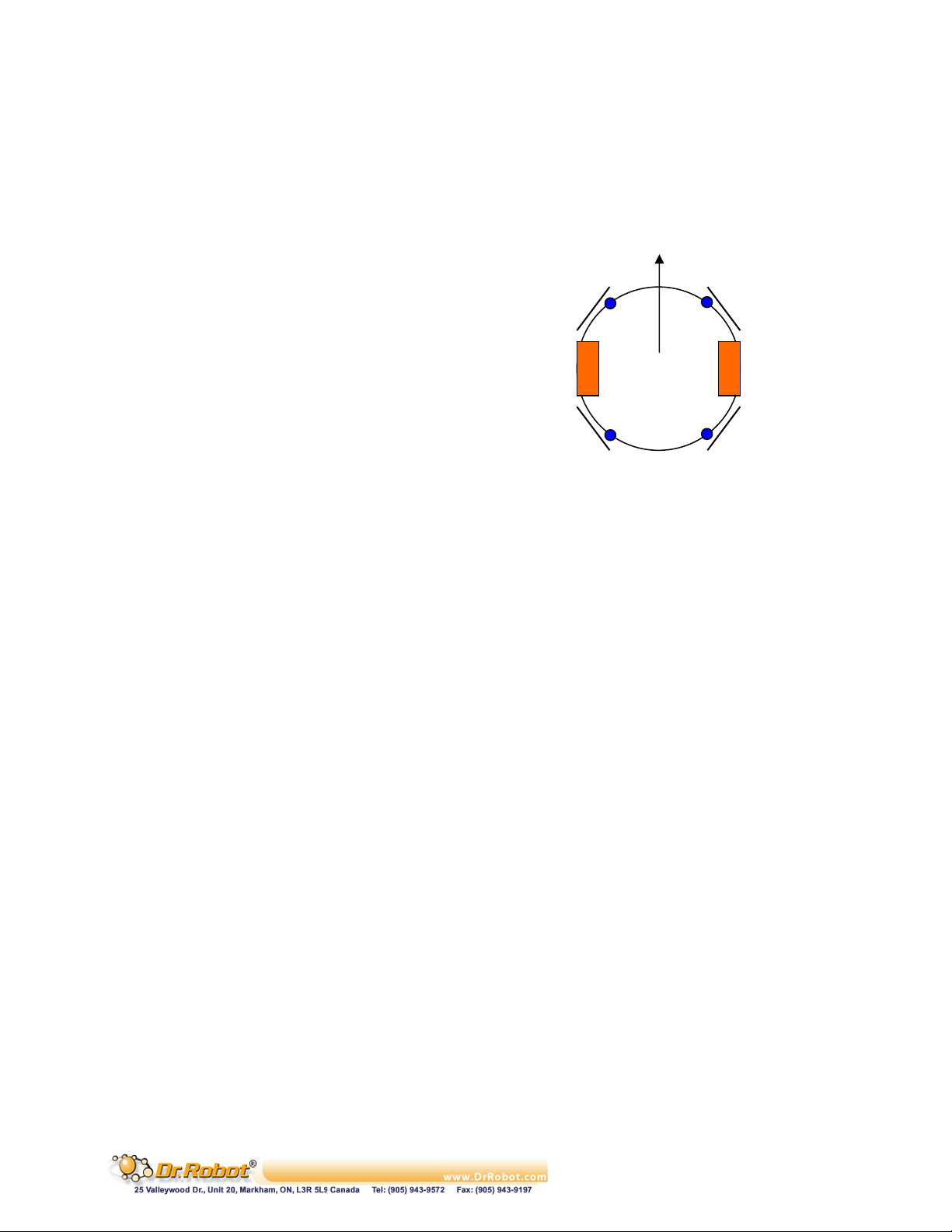
V. WiRobot DRK6080/6000/8080/8000 Specific APIs
V.1 Low Level Protection
When bumpers (optional) are installed on WiRobot
RDK6080/6000/8080/8000 with the connection
configuration shown on the right, a build-in low-level bumper
collision protection scheme can be enabled or disabled with
the next two commands. When this bumper protection
feature is enabled:
. The wheels will stop moving forward when either
bumper 0 or 1 is engaged, there will be not affect if
the wheels are moving backward.
. The wheels will stop moving backward when either
bumper 2 or 3 is engaged, there will be not affect if
the wheels are moving forward.
. The bumpers are connected to custom digital I/O
0, 1, 2, and 3.
126 void EnableBumperProtection();
Description: This will enable the low level bumper protection feature.
EnableBumperProtection xxxx.
Syntax: EnableBumperProtection ();
Parameter: void;
Return value: void
Remarks:
By default, the bumper protection feature is disabled when system is booted up.
Bumper_0 Bumper_1
D_IN0 D_IN1
Left
Wheel
D_IN2 D_IN3
Bumper_2 Bumper_3
Figure V.1 WiRobot RDK6080 / 6000
/ 8080 / 8000 Bumper Connection
Configuration
Front
Right
Wheel
127 void DisableBumperProtection();
Description: This will disable the low level bumper protection feature.
DisableBumperProtection xxxx.
Syntax: DisableBumperProtection ();
Parameter: void;
Return value: void
Copyright © Dr Robot Inc. 2005
65
Page 67

Chapter IV. WiRobot Module
Copyright © Dr Robot Inc. 2005
66
Page 68

I. PMS5005 Sensing and Motion Controller
I.1 Introduction
The PMS5005 Robot Sensing/Motion Controller can be used as sensing, control, motion execution,
LCD display and wireless communication processing unit for various robotic applications. Its onboard
firmware makes the low level function modules such as motor driver module and wireless
communication module transparent to the users. A host (e.g. PC, DSP, or processor) will be used to
communicate and control the PMS5005 for different applications through the UART (serial) interface.
The system can help robotic and AI researchers and developers focus on the high level logic and
algorithm design, and avoid the hassle of writing low level device drivers, standard control schemes
and troubleshooting the electronic circuits. The ease of use, powerful functionality and onboard
intelligence can eliminate design risk, streamline hardware and software development, and
significantly shorten the time to delivery while effectively reducing the cost. Typical applications
include humanoid robot, legged robot, wheel-based robot, robot head, robot arm and robot hand.
I.1.1 PMS5005 Robot Sensing/Motion Controller Architecture
As shown in Figure I.1, the PMS5005 features functionalities required by most of the robotic
applications, such as sensing, motion control, and data communication.
The PMS5005 contains the following features and capabilities:
- 40MIPS 16-bit fix-point hybrid DSP/MCU
- 36K x 16-bit words flash
- 2.5K x 16-bit words SRAM
- Build-in
. A/D reference voltage monitoring
. Over-heating sensor (x2)
. System voltage monitoring (x1)
. Watchdog timer (x1)
. Full duplex UART (x2)
- Embedded firmware for configurable closed loop position, velocity, various sensor data acquisition,
LCD graphic display, wired and wireless communication
- Interfaces to
. MDM5253 DC motor driver module with position and current feedback (x2), which includes
o General-purpose PWM DC motor interface (x6)
o Motor current feedback interface (x6)
o Potentiometer position feedback sensor interface (x6)
. Quadrature encoder (x2)
. Standard RC servo motor (x6)
. DUR5200 Ultrasonic range sensor module (x6)
. DHM5150 Human sensor module (x2)
. DAT5280 Ambient temperature sensor module (x1)
. GP2Y0A21YK Infrared range sensor (x1)
. DTA5102 2 axis tilt/acceleration sensor module (x1)
. Custom A/D (x 8 including 3 channels of optional battery voltage monitoring). It can connect to
MSA3502 if signal amplifying is needed.
. Custom digital input (x8)
. Custom digital output (x8)
. MGL5128 Graphic LCD display module (128 x 64) (x1)
. MIR5538/5540 Full duplex infrared remote control and communication module (x1)
Copyright © Dr Robot Inc. 2005
67
Page 69
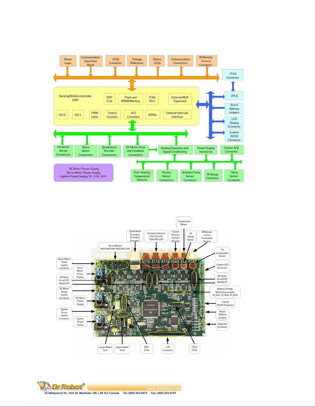
. PMB5010 Multimedia controller (x1)
. MCB3100 Serial Bluetooth wireless module or MCR3210 RS232 interface module (x1) or
WFS802b WiFi802.11b Serial wireless module
Figure I.1 Block Diagram of the PMS5005
I.1.2 PMS5005 Connectors and Jumpers
Figure I.2 shows the function and location of the connectors and jumpers on the PMS5005.
Copyright © Dr Robot Inc. 2005
Figure I.2 PMS5005 Connector and Jumper Locations
68
Page 70
* Note that the size of the PCB board of PMS5005 is about 14.5cm x 10.2cm.
I.2 Operations
The PMS5005 Robot Sensing/Motion Controller is designed to be running as part of the WiRobot
system. The hardware preparation when using the PMS5005 is just simply connecting the relevant
WiRobot modules to the relevant connectors on the PMS5005 board and setting the proper jumper
configurations. Lower device-level operations are handled by the firmware embedded in PMS5005
controller with the following functions:
. Control 6 RC servos
. Driver for LCD display, 6 ultrasonic sensors, 2 human sensors, 1 infrared distance sensor, 1
temperature sensor, 1 tilt/acceleration sensor and 1 infrared remote sensor
. Can interface with different digital devices through the general digital input and output ports
. Can interface with different analog devices through the A/D ports
. Built-in voltage monitoring capability
. Built-in 3 DC motor control schemes, including open-loop PWM control, closed-loop position
control, and closed-loop velocity control. Closed-loop position and velocity control required
the use of encoder or rotary sensor as the feedback device
Users can physically connect the PMS5005 to a host (e.g. PC, processor, or DSP) through null
modem cable or serial wireless modules. By default, the PMS5005’s UART setting is 115200, 8, N, 1
with hardware flow control. With this connection, there are two ways to communicate with the
PMS5005:
1. Using WiRobot SDK Software (requires Microsoft platform): High level programs running on
PC can communicate with the PMS5005 firmware using WiRobot SDK Component and
supplied WiRobot Gateway program. Users simply need to make a function call in their
programs to obtain sensor information or to control different devices (e.g. servos, DC motors,
and etc.) without the needs to understand the communication details between PC and
PMS5005. Please refer to the Chapter III. WiRobot SDK API (Page 26) for further
information on programming.
2. Using PMS5005 Communication Protocol: A device (e.g. PC, processor, or DSP) can
communicate with PMS5005 directly using packet-level commands. Such option has no
requirement on the host and provides the freedom for users to choose their development
platform.
I.2.1 PMS5005 Power Supplies and Consumption
Up to three independent groups of power supply can be connected to the PMS5005 supporting board
system circuits (System Power Supply), DC Motor Power Supply and Servo Motor Power Supply
respectively. These power supplies could be connected to the PMS5005 either through the screw
terminals or through the power jacks. Near each screw terminal, there is a connector port for
connecting the power switch or emergency button for each power supply. By default, all three
connector ports are connected together. If power switches are needed, you could disconnect the
connection and add a switch in between for each connector port.
Table I.1 shows the specification of the power supplies. Refer to Section II.2.5 for the connections of
the power jacks and terminals.
Table I.1 Specification of Power Supplies
Power Supply Power
Copyright © Dr Robot Inc. 2005
Jack
Screw
Terminals
Switch
Connector
Voltage
Range (V)
Current Capacity
(mA)
69
Page 71
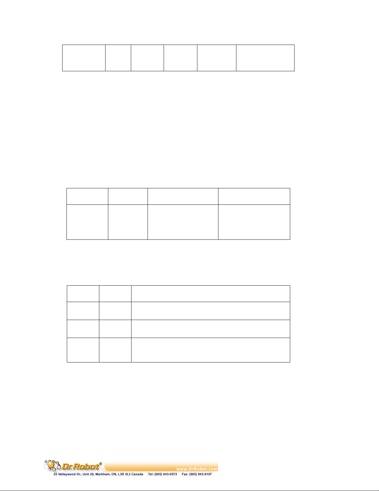
System J1 PSY S1-0 5.5 – 7.2 500
DC Motor J2 PDM S1-1 6.0 – 25.0 System Specific
Servo Motor J3 PSM S2-1 5.0 – 7.2 System Specific
The system power supply is required at all time for the operation of this board and the power
consumption of PMS5005 without connecting any peripheral modules is about 350mA using a 7.2V
battery pack. We also recommend the use of three different power sources in powering the
PMS5005 (System Power Supply, DC Motor Power Supply and Servo Motor Power Supply) since
high power consumption devices (e.g. high torque servos) may affect the operation of voltage
sensitive devices (e.g. sensors) due to voltage frustration.
Note: Please make sure that the DC motor power supply voltage does not exceed the maximum
allowable voltage for the DC motors.
I.2.2 PMS5005 Jumper Settings
The board address jumpers can be set to any value between 0 and 15. The board address is currently
reserved for future use.
Table I.2 Board Address Jumpers B_ADDR
Bit Pin Value 1 Value 0
0 (LSB) 1, 2 open 1-2 short
1 3, 4 open 3-4 short
2 5, 6 open 5-6 short
3 (MSB) 7, 8 open 7-8 short
JP_AD1, JP_AD2 and JP_AD3 are used for enabling and disabling battery voltage monitoring. If the
jumper is removed, the corresponding power supply monitoring and custom AD_IN will be disabled.
Table I.3 Battery Voltage Monitoring Jumpers
Jumper Position Battery Voltage Monitoring
1-2 Enable system power supply monitoring JP_AD1
2-3 Disable system power monitoring and connect Custom AD_IN1
1-2 Enable DC motor power supply monitoring JP_AD2
2-3 Disable DC motor power and connect Custom AD_IN2
1-2 Enable servo motor power supply monitoring JP_AD3
2-3 Disable servo motor power monitoring and connect Custom
AD_IN3
I.2.3 PMS5005 System Communication Connections
Under the WiRobot system architecture, all controllers are connected in a chain. There is one and only
one host serving as the central controller. All other embedded controllers have at least two SCI ports
for the system communications: upper-reach port and lower-reach port, with the direction respect to
the central controller.
The system communication connection structure of the PMS5005 in the WiRobot system is shown in
Figure I.1. PMS5005 can work solely in the WiRobot system or together with WiRobot Multimedia
Controller PMB5010 when multimedia data (video and audio) is required in the system.
Copyright © Dr Robot Inc. 2005
70
Page 72
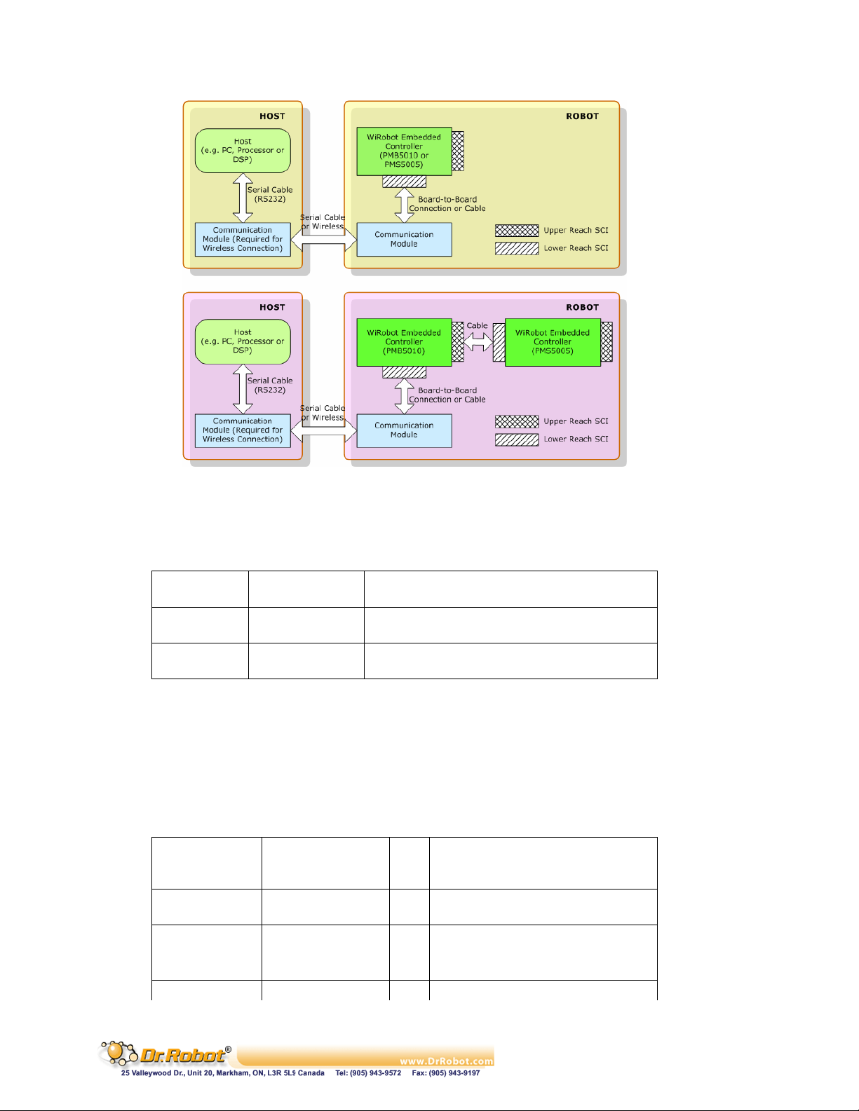
Figure I.3 WiRobot System Communication Architecture
The system communication connectors on the PMS5005 are described in Table I.4. Refer to Section
I.2.5 for the definitions of the signals attached to the connector BTOOTH and SCI.
Table I.4 System Communication Connectors
Connector Type Description
BTOOTH Upper Reach SCI port with handshaking and control signals for
both wired and wireless modules
SCI Lower Reach Two-wire serial communication interface (reserved
for future use)
I.2.4 Connecting Peripheral Modules Supported by PMS5005
Table I.5 lists the WiRobot peripheral modules that can be directly connected to the PMS5005 board
and supported by the firmware embedded in PMS5005. Refer to the relevant chapter of these
peripheral modules for the detailed technical information.
Table I.5 Peripheral Modules Supported by PMS5005
Peripheral
Module
WFS802b BTOOTH 1 WiFi802.11 wireless communication
MCB3100 BTOOTH 1 Bluetooth wireless communication
MCR3210 BTOOTH 1 RS232 interface module
DUR5200 US_1 – 6 6 Ultrasonic range sensor
Copyright © Dr Robot Inc. 2005
Connector Max
No.
module
module
Description
71
Page 73
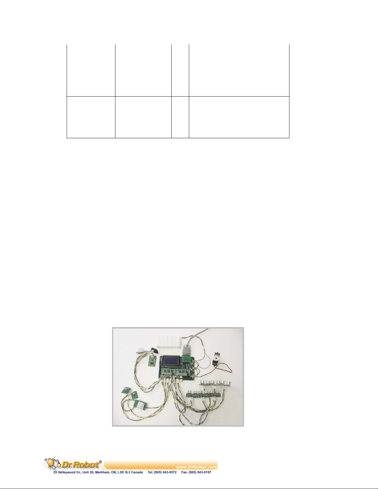
DTA5102 TILT 1 2-Axis tilting and acceleration sensor
DHM5150 HUMAN1 – 2 2 Human motion sensor
DAT5280 TEMPERATURE 1 Ambient temperature sensor
MIR5538/5540 INFRAR 1 Infrared remote controller module
MDM5253 MOTOR1_IN, _OUT
MOTOR2_IN, _OUT
3rd party SM1 - 6 6 3rd party servo motor
3rd party ENCODER1 - 2 2 3rd party quadrature encoder
GP2Y0A21YK RANGE 1 Infrared range sensor
MGL5128 LCD 1 Mono Graphic LCD display module,
2 3-channel DC motor driver module with
position and current feedback
128x64
I.2.5 Connecting DC Motors and Potentiometers to PMS5005
In order to connect DC motors and potentiometers to the PMS5005, MDM5253 (DC Motor Driver
Module with Position and Current Feedback) is required. Each MDM5253 can control up to 3 DC
motors and 3 potentiometers; and each PMS5005 can connect up to 2 MDM5253. The
potentiometer can be used as the position feedback of the DC motor for precise position and velocity
control. Connector MOTOR1-IN and MOTOR1-OUT on PMS5005 are used to connect to a
MDM5253 for DC Motor 1, 2, 3 and Potentiometer 1, 2, 3; and connector MOTOR2-IN and MOTOR2OUT are used to connect to a MDM5253 for DC Motor 4, 5, 6 and Potentiometer 4, 5, 6. For details
on how to connect DC motors and potentiometers to the MDM5253, please refer to the Chapter IV.III
MDM5253 (Page 89).
I.2.6 Connecting Custom Sensors/Devices to PMS5005
The PMS5005 has 8 digital inputs, 8 digital outputs and 8 custom A/D extensions. These ports can all
be used to connect to different sensors or output devices. For example, user can connect gyroscope,
more infrared distance sensors or other analog signal devices to PMS5005 by making use of the
available A/D extensions. If a user just wants to have better infrared sensing capabilities in his / her
robot, the PMS5005 can support up to 9 infrared distance sensors (GP2Y0A21YK) through its IR
range sensor port and the 8 custom A/D expansions.
I.2.7 Sample WiRobot Connection Using PMS5005
The following figure illustrates a simple way in using the PMS5005. Note that only a single 7.2V
power source is used to supply power to the system and not all peripheral modules are connected to
the PMS5005 in this figure.
Figure I.4 Sample Connection of WiRobot PMS5005 with Different Peripheral Modules
Copyright © Dr Robot Inc. 2005
72
Page 74
I.2.8 PMS5005 Connections
The definitions of the connector signals of the power supplies and the supported PMS5005
peripheral modules are listed in the following tables.
Table I.6 Connections of the Power Jacks and Terminals
Power Connection Power Jack J1, J2, J3 Screw Terminal PSY, PDM, PSM
Positive Power Source Center Pin 1
Power Supply Ground Circle 2
Table I.7 Upper Reach Communication Port BTOOTH
Pin Name Signal Description
1 VCC +3.3 V
2 RXD Data receiving
3 TXD Data transmitting
4 RTS Request to send
5 CTS Clear to send
6 GND Power supply ground
7 COMRST Reserved
8 BTIN Reserved
Table I.8 Lower Reach Communication Port SCI
Pin Name Signal Description
1 VCC +3.3 V
2 RXD Data receiving
3 TXD Data transmitting
4 GND Power supply ground
Table I.9 Ultrasonic Range Sensor Connectors US_1 - 6
Pin Name Signal Description
1 VCCA +5.0 V
2 URS Ultrasonic echo receiving signal, active rising edge
3 UTE Ultrasonic transmitting enable, active high
4 GND Power supply ground
Copyright © Dr Robot Inc. 2005
Table I.10 Tilt and Acceleration Sensor Connector TILT
73
Page 75
Pin Name Signal Description
1 VCCA +5.0 V
2 AYD Y direction signal, analog 0 – 3.0V
3 AXD X direction signal, analog 0 – 3.0V
4 GND Analog ground
Table I.11 Human Motion Sensor Connectors HUMAN1 - 2
Pin Name Signal Description
1 VCCA +3.0 V
2 HMS Human motion signal, analog 0 – 3.0V
3 HAS Human presence alarm, analog 0 – 3.0V
4 GND Analog ground
Table I.12 Temperature Sensor Connector TEMPERATURE
Pin Name Signal Description
1 VCCA +5.0 V
2 TVS Temperature Data, analog 0 – 3.0V
3 GND Analog ground
Table I.13 Infrared Remote Controller Connector INFRAR
Pin Name Signal Description
1 VCC +3.3 V
2 IRX Receiving from external device, digital
3 ITX Transmitting to external device, digital
4 GND Power supply ground
Table I.14 Servo Motor Connectors SM1 - 6
Pin Name Signal Description
1 SCL Servo motor control
2 VSM Positive servo motor power supply
3 GND Servo motor power supply ground
Table I.15 Quadrature Encoder Connector ENCODER1 - 2
Copyright © Dr Robot Inc. 2005
74
Page 76
Pin Name Signal Description
1 ENCB Channel B signal
2 VCC +3.3V
3 ENCA Channel A signal
4 ENCI Index signal (reserved for future use)
5 GND Power supply ground
Table I.16 Infrared Range Sensor Connector RANGE
Pin Name Signal Description
1 VCC +5.0 V
2 RVS Range data, analog 0 – 3.0V
3 GND Analog ground
Table I.17 LCD Display Connector LCD
Pin Signal Description
1 VDD +5.0V, power supply for logic
2 VSS Power supply ground
3 Vo LCD operating voltage
4 D0 Data bit 0
5 D1 Data bit 1
6 D2 Data bit 2
7 D3 Data bit 3
8 D4 Data bit 4
9 D5 Data bit 5
10 D6 Data bit 6
11 D7 Data bit 7
12 CS1 Column select 1 ~ 64
13 CS2 Column select 65 ~ 128
14 RESET Reset input
15 R/W Read/write
16 D/I Data/Instruction indication
17 E Enable
18 VEE Negative voltage output
19 A Power supply for LED backlight (+)
20 K Power supply for LED backlight (-)
Copyright © Dr Robot Inc. 2005
Table I.18 Custom A/D Expansion Connector EXP-AD
75
Page 77
Pin Signal Description
1, 2, 3, 4 + 3.0 V Analog power supply, max. 40mA
5, 6, 15, 16 Ground Analog ground
7 AD_IN1* Analog 0 – 3.0V
8 AD_IN2* Analog 0 – 3.0V
9 AD_IN3* Analog 0 – 3.0V
10 AD_IN4 Analog 0 – 3.0V
11 AD_IN5 Analog 0 – 3.0V
12 AD_IN6 Analog 0 – 3.0V
13 AD_IN7 Analog 0 – 3.0V
14 AD_IN8 Analog 0 – 3.0V
*Note (Table I.18): When the relevant power supply voltage monitoring is enabled, AD_IN1, AD_IN2,
AD_IN3 will be not available to the custom A/D expansions.
Table I.19 Custom Digital I/O Expansion Connector EXP-GPIO
Pin Signal Description
1, 2, 3, 4 + 3.3 V Positive power source, max. 100mA
5 D_OUT0 Digital out
6 D_OUT1 Digital out
7 D_OUT2 Digital out
8 D_OUT3 Digital out
9 D_OUT4 Digital out
10 D_OUT5 Digital out
11 D_OUT6 Digital out
12 D_OUT7 Digital out
13, 14, 15, 16 Ground Power supply ground
17* D_IN0 Digital in
18* D_IN1 Digital in
19* D_IN2 Digital in
20* D_IN3 Digital in
21* D_IN4 Digital in
22* D_IN5 Digital in
23* D_IN6 Digital in
24* D_IN7 Digital in
* NOTE (Table I.19): These pins have been pulled-up to logic high (+ 3.3V) internally.
I.3 Procedure to upgrade the PMS5005 firmware
1. Download and save the latest PMS5005 firmware from www.DrRobot.com
2. Turn off PMS5005 and keep it off until step 9
3. Use a null modem cable to connect the PC to PMS5005 with a RS232 Interface Module
(MCR3210) as shown in Figure I.5. All peripheral modules (e.g. sensors, motors, LCD and etc.)
can still be plugged to the PMS5005 without affecting the upgrade process
Copyright © Dr Robot Inc. 2005
76
Page 78
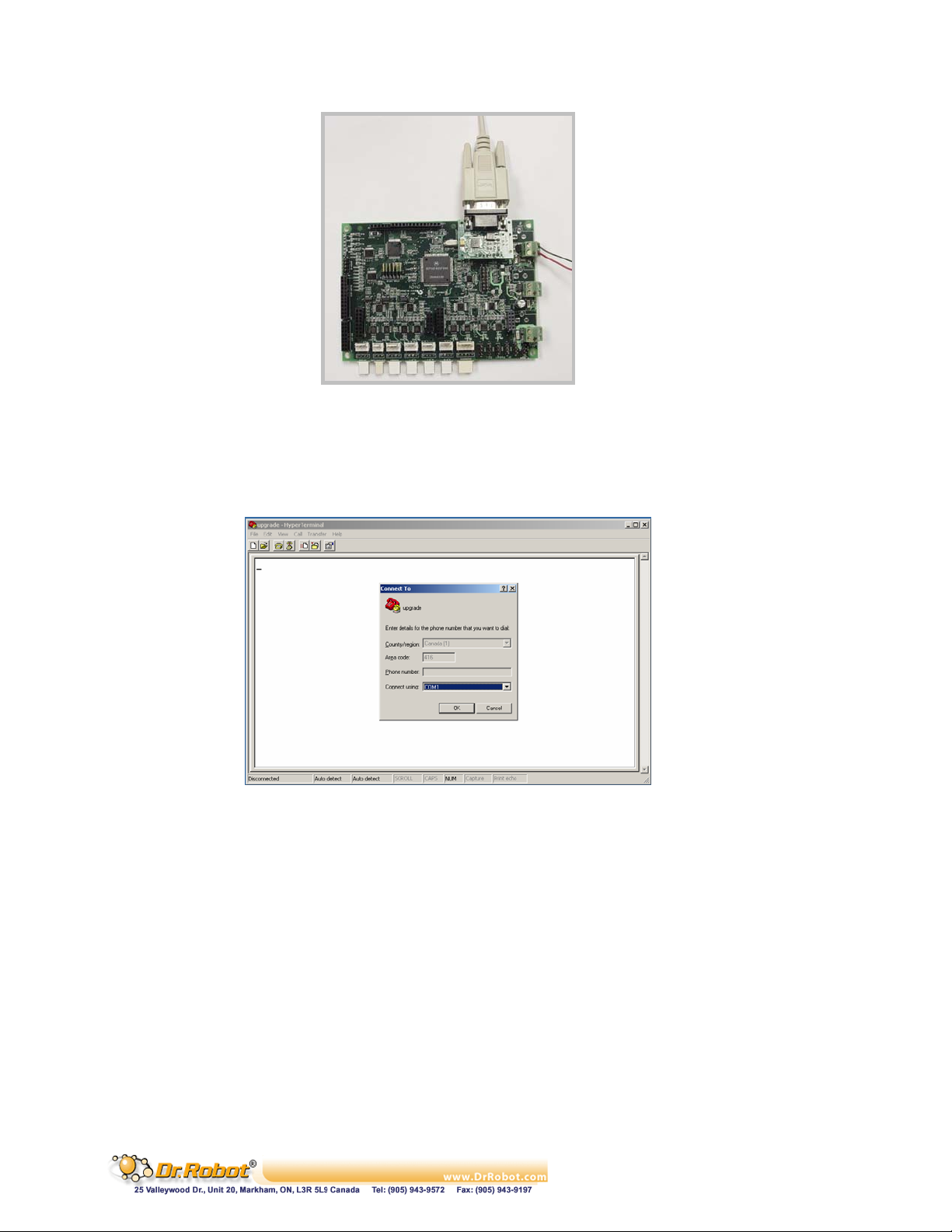
Figure I.5 Physical Connection
4. Close all WiRobot software on PC (e.g. WiRobot Gateway and all sample applications)
5. Start the hyper-terminal (which comes with MS Windows OS), give a name to this new
connection and choose the COM port that is connected to the PMS5005 (normally COM1 or
COM2) as shown in the following figure:
Figure I.6 Choosing COM Port Connection
6. Configure the COM port with the setting 115200, 8, N, 1, Xon/Xoff and turn on the “Echo
typed characters locally” under Properties - > Settings -> ASCII Setup. If your PC is slow, you
can turn off this “echo” option for shorter download time but you will not see the download
process during the upgrade.
Copyright © Dr Robot Inc. 2005
77
Page 79
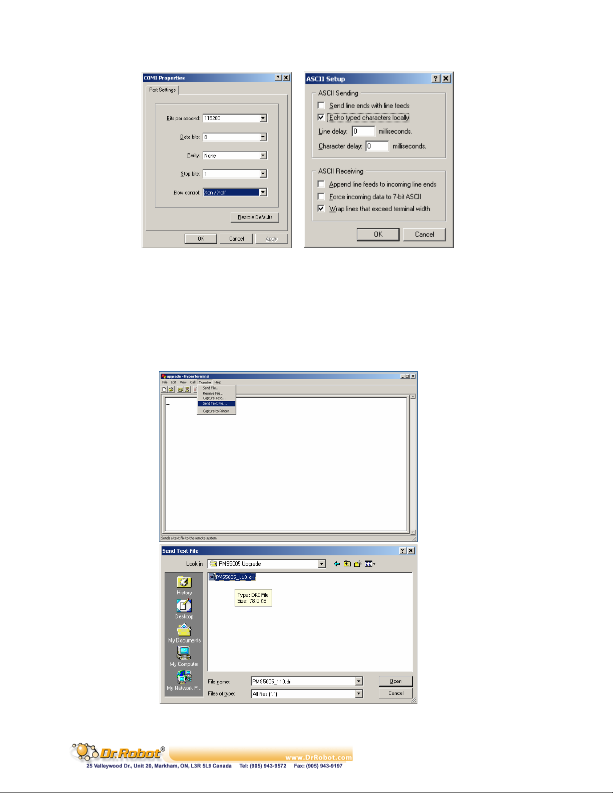
Figure I.7 COM Port Setting
7. The lower left corner of the hyper-terminal will show the connection status. If the hyperterminal is still not connected, click the connect icon on the hyper-terminal to establish the
connection (don’t turn on the PMS5005 yet!).
8. Choose “Transfer -> Send Text File” from the toolbar and set “files of type” to ALL. Locate
the PMS5005 firmware HEX file only by HIGHLIGHTING the file (e.g. PMS5005_v11.dri).
Please make sure that you DON’T double click the file or click the “Open” button
Copyright © Dr Robot Inc. 2005
Figure I.8 Locating the HEX File
78
Page 80
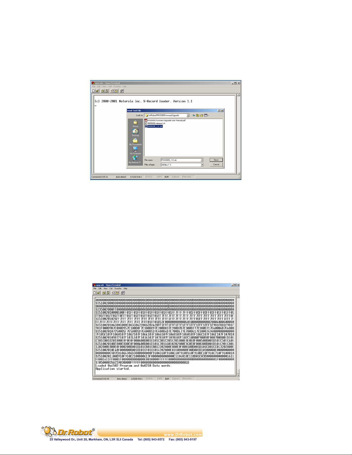
9. Please read step 10-13 ahead before turning on the PMS5005 in this step
10. After you turn on the PMS5005 (by connecting power to the system power), you should see
the text “(c) 2000-2001 Motorola Inc. S-Record loader. Version 1.1” in the hyper-terminal as
shown in the following figure:
Figure I.9 Status after Turning on the PMS5005
11. Within 5 seconds (start counting when you turn on the PMS5005), you should click the
“Open” button on the Hyper-terminal popup window. Firmware download will then start. If
you fail to start the download within this period of time, the original firmware on PMS5005
will automatically start. You have to turn off the PMS5005, and repeat the download
procedure again from Step 2
12. When the download is started, hex numbers will appear on the screen if you have turned on
the “echo” option as described in step 6. Otherwise, you will not see anything but the
download is still running. When the firmware download is completed (takes about 20-60
seconds, depending on the speed of your PC), you will see the “Application Started” keyword
as shown in Figure I.10 no matter the “echo” option is turned on or off. The new downloaded
firmware will automatically start in few seconds and you should see some un-recognized
characters
Figure I.10 Successful PMS5005 Firmware Upgrade
13. When the download is finished, you could disconnect the COM connection in the hyperterminal, and re-start your PMS5005
Copyright © Dr Robot Inc. 2005
79
Page 81
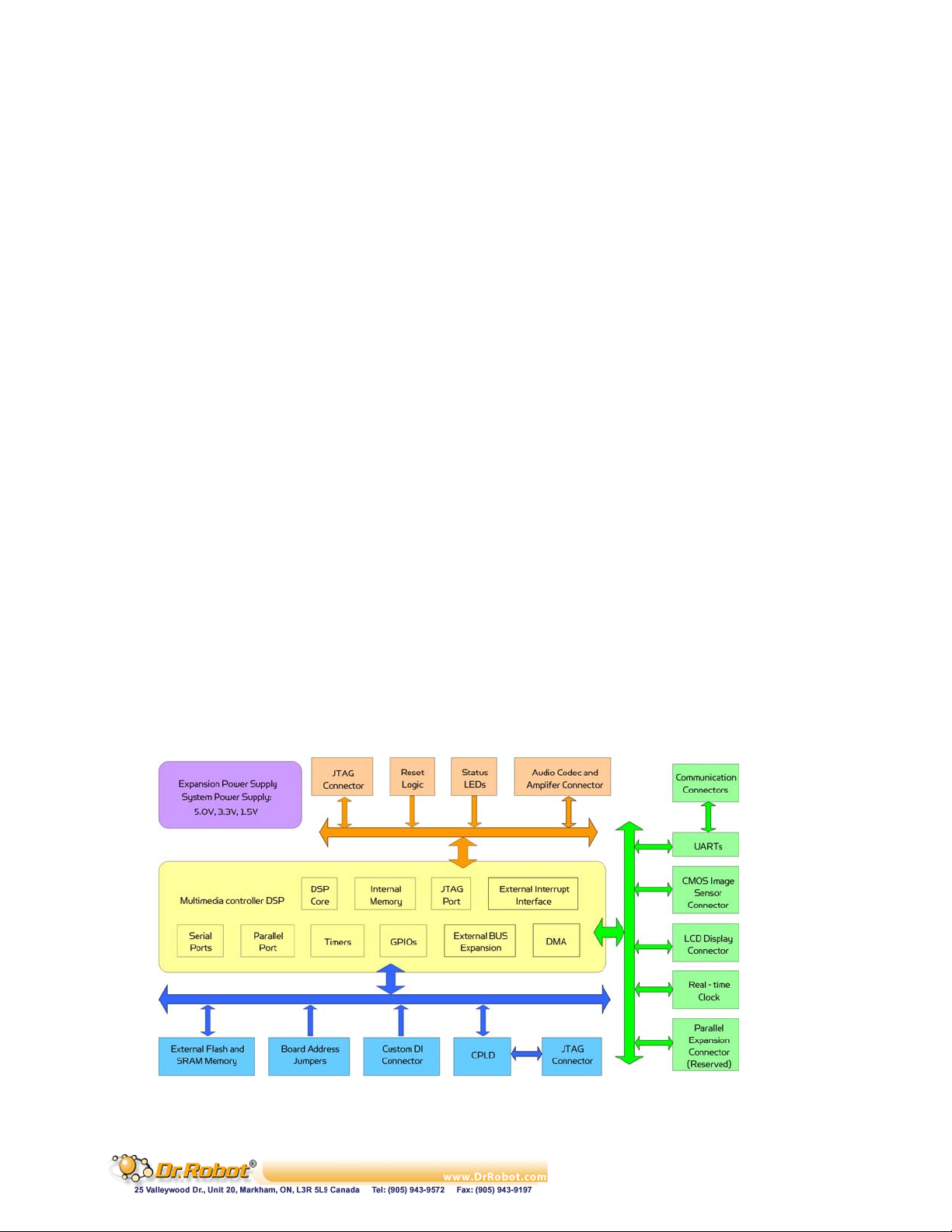
II. PMB5010 Multimedia Controller
II.1 Introduction
The PMB5010 Robot Multimedia Controller can be used as audio, video and wireless communication
processing unit for various robotic applications. Its onboard firmware makes the low level function
modules such wireless communication module transparent to the users. A host (e.g. PC, DSP, or
processor) will be used to communicate and control the PMS5005 for different applications through
the UART (serial) interface. The system can help robotic and AI researchers and developers focus on
the high level logic and algorithm designs, and avoid the hassle of writing low level device drivers,
standard control schemes and troubleshooting the electronic circuits. The ease of use, powerful
functionality and onboard intelligence can eliminate design risk, streamline hardware and software
development, and significantly shorten the time to delivery while effectively reducing the cost. Typical
applications include humanoid robot, legged robot, wheel-based robot, robot head and intelligent
home device.
II.1.1 PMB5010 Multimedia Controller Architecture
The PMB5010 offers multimedia functionalities that are required by most intelligent robotic
applications. Figure II.1 shows the system blocks of the PMB5010.
The key features and capabilities are:
- 120MIPS 16-bit fix-point DSP
- 1M x 16-bit words flash
- Up to 256K x 16-bit words SRAM
- Build-in
. Real-time clock
. Full duplex UART (x2)
- Embedded firmware for image capturing, audio recording and playback, and wired and
wireless communication
- Interfaces to
. MAC5310 Audio codec and amplifier module (x1)
. MCI3908 CMOS image sensor module (352 x 288) (x1)
. MCB3100 Serial Bluetooth wireless module or MCR3210 RS232 interface module (x1)
or WFS802b WiFi802.11b serial wireless module
Copyright © Dr Robot Inc. 2005
Figure II.1 Block Diagram of the PMB5010
80
Page 82
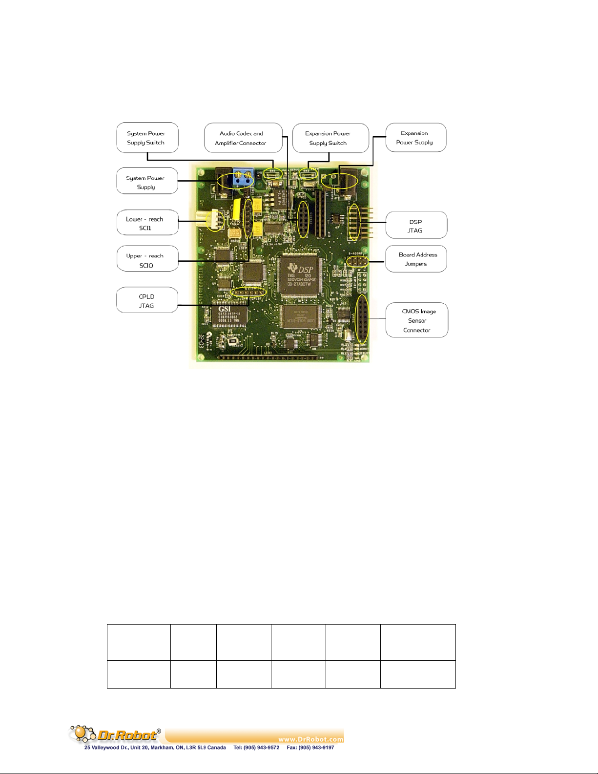
II.1.2 PMB5010 Connectors and Jumpers
Figure II.2 shows the function and location of the connectors and jumpers on the PMB5010.
Figure II.2 PMB5010 Connectors and Jumpers
II.2 Operations
The PMB5010 Robot Multimedia Controller is designed to be running as part of the WiRobot system.
The hardware preparation when using PMB5010 is just simply connecting the relevant peripheral
modules to the relevant connectors on the PMB5010 board and setting the proper jumper
configurations. Lower device-level operations are handled by the firmware embedded in PMS5010
controller. High level programs running on PC or other processors are virtually communicating with
the PMB5010 firmware using either WiRobot SDK Component and supplied WiRobot Gateway
program or packet-level commands. Please refer to the Chapter III. WiRobot SDK API (Page 26) for
using WiRobot SDK and WiRobot Communication Protocol for using packet-level commands.
II.2.1 PMB5010 Power Supplies
Up to two power supplies can be connected to the PMB5010 board supporting board system circuits
(System Power Supply) and Parallel Expansion Module (Expansion Power Supply) (reserved)
respectively. These power supplies can be connected to the board either through the screw terminals
or the power jacks. Near each screw terminal, there are two connector ports for connecting power
switches or emergency buttons. By default, these two ports are connectors together. If the power
switches are needed, you could place a switch for each connector port.
Table II.1 Specification of Power Supplies
Power
Supply
System JT1 PDMT SW1 5.5 – 7.0 500
Expansion JT2 PSYT SW2 5.0 – 7.2 System Specific
Power
Jack
Screw
Terminals
Switch
Connector
Voltage
Range (V)
Current
Capacity (mA)
Copyright © Dr Robot Inc. 2005
81
Page 83
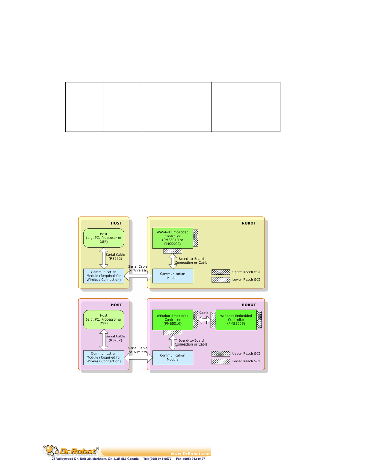
II.2.2 PMB5010 Jumper Settings
The board address can be set to any value between 0 and 15. Please refer to the Table II.2 for the
setting values.
Table II.2 Board Address Jumpers B_ADDR
Bit Pin Value 1 Value 0
0 (LSB) 1, 2 open 1-2 short
1 3, 4 open 3-4 short
2 5, 6 open 5-6 short
3 (MSB) 7, 8 open 7-8 short
II.2.3 PMB5010 System Communication Connections
Under the WiRobot system architecture, all the controllers are connected in a chain. There is one and
only one host serving as the central controller. All other embedded controllers have at least two SCI
ports for the system communications: upper-reach port and lower-reach port, with the direction
respect to the central controller.
The system communication connection structure of the PMS5010 in the WiRobot RDK is shown in
Figure II.3. PMB5010 can work solely in the WiRobot system or together with a WiRobot Sensing
and Motion controller PMS5005.
Figure II.3 WiRobot System Communication Architecture
The system communication connectors on the PMB5010 are described in Table II.3. Refer to Section
II.2.5 for the definitions of the signals attached to the connector BLUETOOTHT and SCIT.
Table II.3 System Communication Connectors
Copyright © Dr Robot Inc. 2005
82
Page 84
Connector Type Description
BLUETOOTHT Upper Reach SCI port with handshaking and control signals for
both wired and wireless modules
SCIT Lower Reach Two-wire serial communication interface
II.2.4 Peripheral Modules Supported by PMB5010
Table II.4 lists the WiRobot peripheral modules that can be directly connected to the PMB5010 board
and supported by the firmware embedded in PMB5010. Refer to the relevant chapter of these
peripheral modules for the detailed technical information.
Table II.4 Sub-modules Supported by PMB5010
Sub-module Connector Max No. Description
WFS802b BLUETOOTHT 1 WiFi802.11b wireless communication
module
MCB3100 BLUETOOTHT 1 Bluetooth wireless communication
module
MCR3210 BLUETOOTHT 1 RS232 interface module
MAC5310 CODEC0 1 Audio codec and amplifier module,
which can be used to connect to
microphone and speaker
MCI3908 IMAGE 1 CIF CMOS image sensor module
II.2.5 PMB5010 Peripheral Module Connections
The definitions of the connector signals of the power supplies and the PMB5010 peripheral modules
are listed in the following tables.
Table II.5 Connections of the Power Jacks and Terminals
Power Connection Power Jack JT1, JT2 Screw Terminal PDMT, PSYT
Positive Power Source Center 1
Power Supply Ground Circle 2
Table II.6 Upper Reach Communication Port BLUETOOTHT
Pin Name Signal Description
1 VCC +3.3 V
2 RXD Data receiving
3 TXD Data transmitting
4 RTS Request to send
5 CTS Clear to send
6 GND Power supply ground
7 COMRST Reserved
8 BTIN Reserved
Copyright © Dr Robot Inc. 2005
83
Page 85
Table II.7 Lower Reach Communication Port SCIT
Pin Name Signal Description
1 VCC +3.3 V
2 RXD Data receiving
3 TXD Data transmitting
4 GND Power supply ground
Table II.8 Audio Codec and Amplifier Module Connector CODEC0
Pin Signal Description
1 ADIN Data input
2 VCC5 + 5.0V
3 AFS Frame sync
4, 6 GND Power supply ground
5 ADOUT Data output
7 ASCK Shift clock
8 AMCK NC
9 RESET Reset output
10 APDN Power down output
11 AFC Request output for secondary communication
12 AVC3 + 3.3V
Table II.9 CMOS Image Sensor Connector IMAGE
Pin Signal Description
1 VCC5 + 5.0V
2 D0 Image data bit 0
3 ISCL I2C Clock
4 D1 Image data bit 1
5 ISDA I2C data
6 D2 Image data bit 2
7 VS Digital image vertical blank pulse input
8 D3 Image data bit 3
9 HREF Digital image horizontal blank pulse input
10 D4 Image data bit 4
11 RCLK Digital YUV signal synchronized clock input
12 D5 Image data bit 5
13 RESET Reset output
14 D6 Image data bit 6
15 GND Power supply ground
Copyright © Dr Robot Inc. 2005
84
Page 86
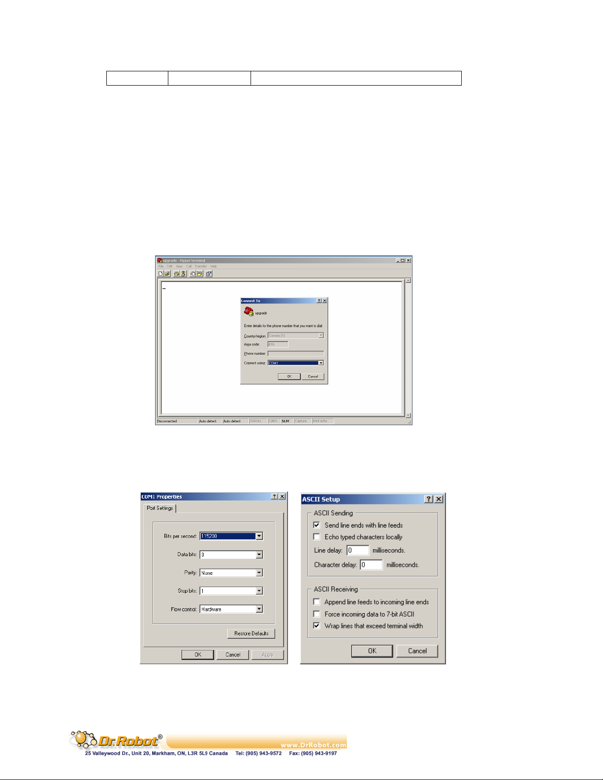
16 D7 Image data bit 7
II.3 Procedure to upgrade the PMB5010 firmware
1. Download and save the latest PMB5010 firmware from www.DrRobot.com
2. Turn off PMB5010 and keep it off until step 9
3. Use a null modem cable to connect the PC to PMB5010. All peripheral modules (e.g. LCD and
etc.) can still be plugged to the PMB5010 without affecting the upgrade process
4. Close all WiRobot software on PC (e.g. WiRobot Gateway and all sample applications)
5. Start the hyper-terminal (which come with MS Windows OS), give a name to this new
connection and choose the COM port that is connected to the PMS5005 (normally COM1 or
COM2) as shown in the following figure:
Figure II.4 Choosing COM Port Connection
6. Configure the COM port with the setting 115200, 8, N, 1, Hardware and turn on “Send line
ends with line feeds” under Properties - > Settings -> ASCII Setup,
Figure II.5 COM Port Setting
Copyright © Dr Robot Inc. 2005
85
Page 87
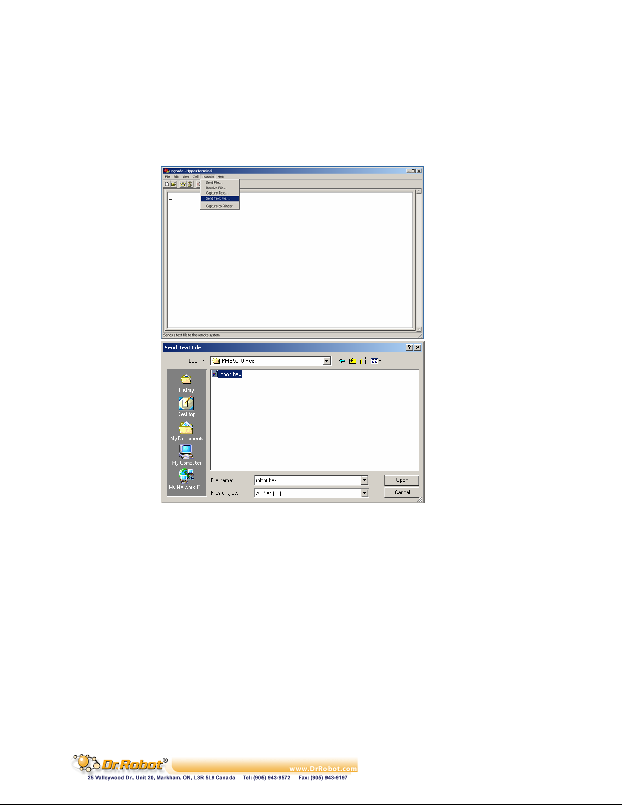
7. The lower left corner of the hyper-terminal will show the connection status. If the hyperterminal is still not connected, click the connect icon on the hyper-terminal to establish the
connection (don’t turn on the PMB5010 yet!).
8. Choose “Transfer -> Send Text File” from the toolbar and set “files of type” to ALL. Locate
the PMB5010 firmware HEX file only by HIGHLIGHTING the file (e.g. robot.hex). Please
make sure that you DON’T double click the file or click the “Open” button
Figure II.6 Locating the HEX File
9. Please read step 10-13 ahead before turning on the PMB5010 in this step
10. After you turn on the PMB5010, you should see the text “Dr. Robot Inc. PMB5010
Bootloader V1.00 All Right Reserved! 2001, 2003” in the hyper-terminal as shown in the
following figure:
Copyright © Dr Robot Inc. 2005
86
Page 88
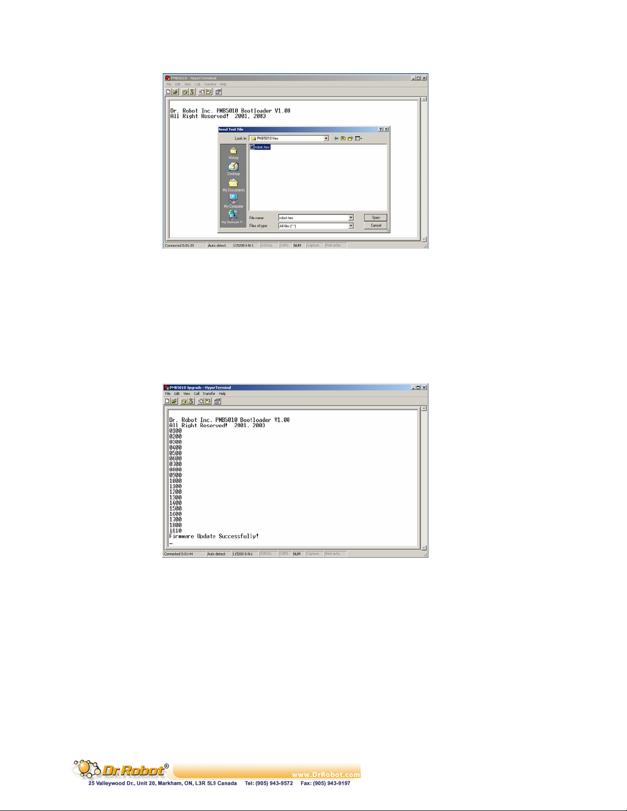
Figure II.7 Status after Turning on the PMB5010
11. Within 5 seconds (start counting when you turn on the PMB5010), you should click the
“Open” button on the Hyper-terminal popup window. Firmware download will then start. If
you fail to start the download within this period of time, the original firmware on PMB5010
will automatically start. You have to turn off the PMB5010, and repeat the download
procedure again from Step 2
12. When the download is started, you will see the following text. At the end, “Firmware Update
Successfully!” will be shown if the download succeeds. The whole process will take about 1
minute
Figure II.8 Successful PMB5010 Firmware Upgrade
13. When the download is finished, you could disconnect the COM connection in the hyperterminal, and re-start your PMB5010
Copyright © Dr Robot Inc. 2005
87
Page 89

III. MDM5253 DC Motor Driver Module with Position and Current
Feedback
III.1 Introduction
The MDM5253 DC Motor Driver Module with Position and Current Feedback is a three-channel Hbridge switching power amplifier board. It can be directly controlled by motion controller’s logic level
PWM driving signals at a frequency up to 20 KHz. For each of the three independent channels, the
MDM5253 also provides the current feedbacks and connectors for position sensors such as
potentiometers. Each channel is able to drive inductive DC load with current up to 5.0 A and operating
voltage ranging from 5.0 V to 28.0 V.
III.1.1 Features
. 3 Independent channels
. Output 5.0 V to 28.0 V operations
. Up to 5.0 A inductive DC load current capability
. 5.0 V TTL/CMOS compatible Inputs
. PWM Frequencies up to 20 kHz
. Automatic PWM over-current limiting
. Output short circuit protection
. Over-temperature output current reduction and shutdown
. Under-voltage shutdown
. Analog output current feedback
. 3 Connectors for position feedbacks
. Directly plug-on to the WiRobot PMS5005 sensing and motion controller board
III.1.2 Applications
. DC motor and stepper motor control
. Permanent magnet solenoid control
. Robotic systems
. General PWM power amplifier
III.2 Operations
III.2.1 Theory of Operation
When four switches configured as that in Figure III.1, the whole circuit is called an H-bridge. By
controlling the on/off of four switches in certain patterns, the polarity of the supply power on the
control output can be changed. For example, when Control Input 1 and 4 are ON while the Control
Input 2 and 3 are OFF, the controlled load is supplied by power with + on the left and – on the right.
When Control Input 1 and 4 are OFF while the Control Input 2 and 3 are ON, the controlled load is
supplied by power with - on the left and + on the right.
When applying the H-bridge output to a DC motor or other inductive loads with PWM controlled
switching command based on certain algorithms and the feedback signals, full bidirectional magnitude
control, including speed, position and torque control, can be achievable.
Copyright © Dr Robot Inc. 2005
88
Page 90
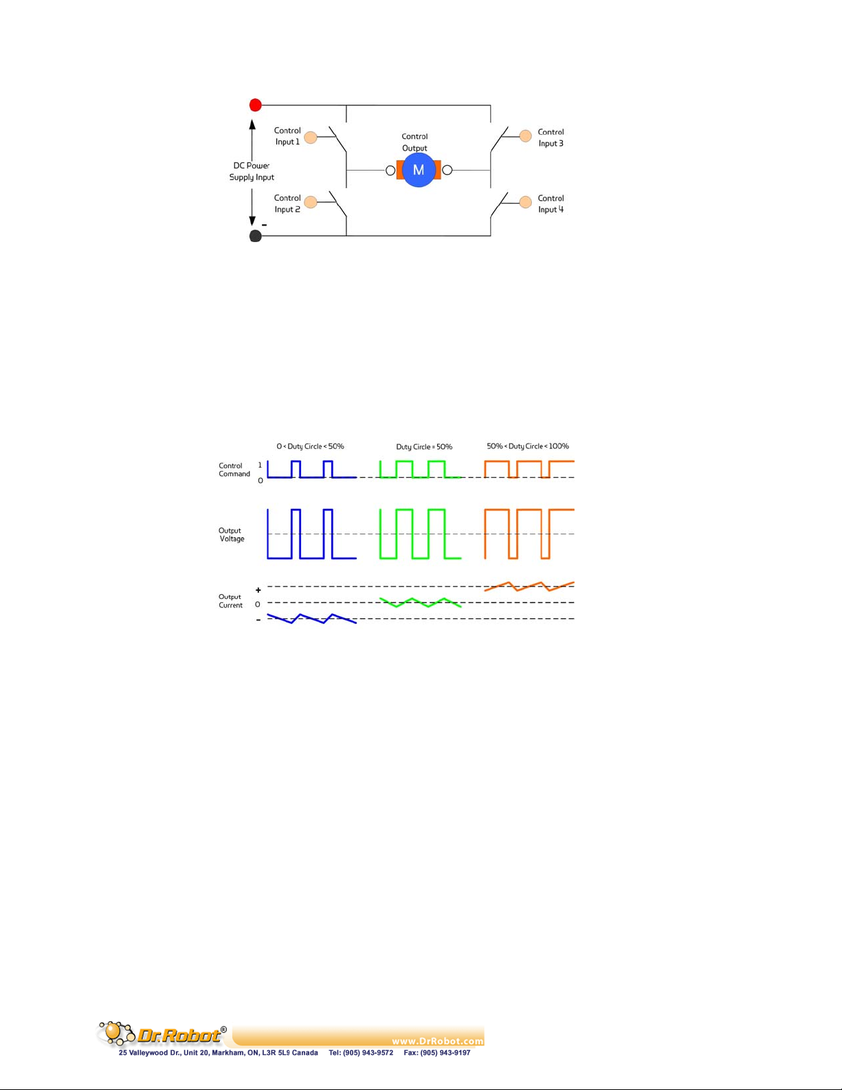
Figure III.1 H-Bridge Switching Device
In the design of the MDM5253, only one PWM control signal is required to control both the direction
and the magnitude of the output for each channel. The H-bridge’s diametrical opposite pairs (control
input 1 and 4, control input 2 and 3) are connected and driven HIGH and LOW together, and the two
pairs are controlled with strictly inverted signals.
Figure III.2 shows the relationship between the PWM duty cycle and system output. The zero average
output occurs when the duty circle is 50%. The direction of the output (in speed control, for example,
the direction of rotation) depends on whether the duty circle is larger than 50% or lower. The
magnitude of the output (rotation speed in speed control) depends on the absolute difference
between the duty circle and 50%.
Figure III.2 Theoretic waveforms of PWM control for the MDM5253
In addition to the PWM control, the MDM5253 can connect up to 3 sensing feedback devices (e.g.
MRS3302). DC motor control schemes, such as position and velocity control, can be implemented by
installing feedback device on DC motor and connecting these devices to MDM5253.
III.2.2 Running as Part of WiRobot System
When using the MDM5253 with the WiRobot system, users simply plug the module onto one of the
DC motor drive expansion connector sets on the PMS5005 Sensing and Motion Controller board
(maximum of 2 MDM5253 modules are supported) and the PMS5005 on-board firmware and device
driver will take care of the motor control and sensing feedback. Since PMS5005 can support 2
MDM5253, it is able to connect and control up to 6 DC motors and have 6 position sensor channels
(POT1-POT6).
Users have an option to use single rotary sensor (e.g. MRS3302 on the Position Sensor Connector),
dual rotary sensor (e.g. 2 MRS3302 on 2 Position Sensor Connectors), or single encoder (Encoder
port on PMS5005) as the feedback device to control each DC motor, if needed. PMS5005 already
has built-in DC motor control schemes and users simply need to select the type of the feedback device
for each DC motor. Note that for single rotary sensor setting, DC motor 1 must use POT1, DC motor 2
must use POT2 and etc.; for dual rotary sensor setting, DC motor 1 must use POT1 and POT6, DC
motor 2 must use POT2 and POT5 and DC motor 3 must use POT3 and POT4; for encoder setting,
DC motor 1 must use ENCODER1 and DC motor 2 must use ENCODER2.
Copyright © Dr Robot Inc. 2005
89
Page 91
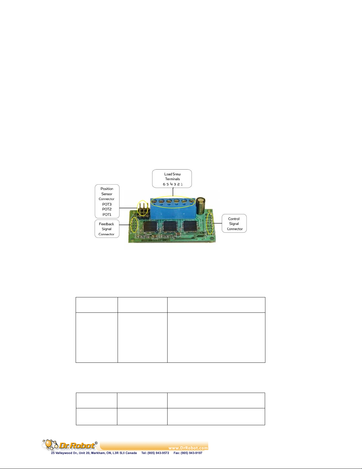
By working with the PMS5005, users can simply call a function offered by the WiRobot SDK
software on PC (requires Microsoft platform) or send a data packet (platform independent) to control
the DC motors or to obtain the sensor feedback. Please refer to Chapter III. WiRobot SDK API (Page
26) and Chapter IV.I PMS5005 (Page 67) for the available motor control algorithms and schemes.
III.2.3 Running as a General Purpose DC Motor Driver Module
When using the MDM5253 with third party controllers, the power supply and the input/output signals
should be connected properly (please refer to Section III.3 for connection setting). The controller
sends control commands to the enable pins and the PWM input pins based on your own control
schemes and get current and position feedback data via an analog to digital converter.
III.3 Connections
III.3.1 Board Structure
Figure III.3 shows the structure, locations and functions of the connectors on the MDM5253 module
board.
Figure III.3 MDM5253 Connector Locations
III.3.2 Connector Description
The definitions of the MDM5253 connector signals are listed in the following tables.
Table III.1 Connections of the Load Screw Terminals MOTOR
Terminals Name Description
1 OUT1A Channel #1 output A
2 OUT1B Channel #1 output B
3 OUT2A Channel #2 output A
4 OUT2B Channel #2 output B
5 OUT3A Channel #3 output A
6 OUT3B Channel #3 output B
Table III.2 Position Sensor Connectors POT1 - 3
Pin Name Function
1 VCC3 + 3.0 V
2 PVS Position data, analog 0 – 3.0 V
Copyright © Dr Robot Inc. 2005
90
Page 92
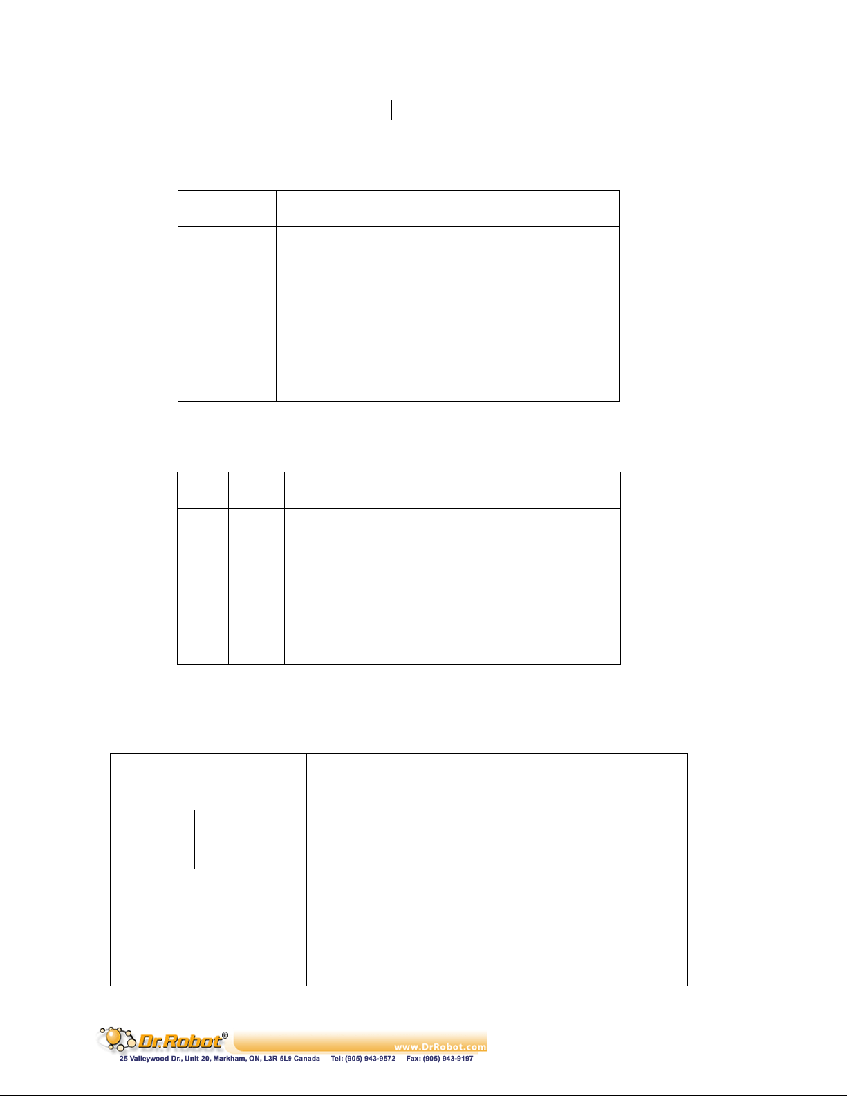
3 GND3 Signal ground
Table III.3 Control Signal Connector MOTOROUT
Pin Name Function
1 CTL1 Channel #1 PWM control signal
2 CTL2 Channel #2 PWM control signal
3 CTL3 Channel #3 PWM control signal
4 ENA Output enable for all channels:
High: enable; Low: disable
5, 6 GND5 Power supply ground for VCC5
7, 8 VCC5 + 5.0 V
9, 10, 11, 12 GNDM Power supply ground for VCCM
13, 14, 15, 16 VCCM Positive load power source
Table III.4 Feedback Signal Connector MOTORIN
Pin Name Function
1, 2 VCC3 + 3.0 V, positive power source for position sensors
3, 4 GND3 Power supply ground for VCC3
5 CFB1 Channel #1 current feedback data, , analog 0 – 3.0 V
6 CFB2 Channel #2 current feedback data, , analog 0 – 3.0 V
7 CFB3 Channel #3 current feedback data, , analog 0 – 3.0 V
8 PFB1 Channel #1 position feedback data, , analog 0 – 3.0 V
9 PFB2 Channel #2 position feedback data, , analog 0 – 3.0 V
10 PFB3 Channel #3 position feedback data, , analog 0 – 3.0 V
III.4 Specifications
Table III.5 MDM5253 Specification
Parameter Conditions MIN TYP MAX Unit
Power Operating Voltage VCCM 5.0 28.0 V
UnderVoltage
Shutdown
Logic Operating Voltage VCC5 4.5 5.0 5.5 V
Position Sensor Power Supply VCC3 3.0 3.3 V
Standby Supply Current VENA = 0V, IOUT = 0A 65 mA
Control Input HIGH VENA, VCTL 3.5 V
Control Input LOW VENA, VCTL 1.4 V
Enable Input Current IENA 25 100
Switch-off VCCM 4.15 4.4 4.65 V
Switch-on VCCM 4.5 4.75 5.0 V
Hysteresis 150 mV
μA
Copyright © Dr Robot Inc. 2005
91
Page 93
PWM Input Current ICTL ± 1
Output-on Resistance
DC Load Current
ROUT
T < 150 ˚C
T = 25 ˚C
T = 150 ˚C
120
300
5.0 A
μA
mOhm
Over-current Protection 7.0 A
Over-temperature Protection
Thermal shutdown 175
Hysteresis 10 30
˚C
PWM Frequency 20 KHz
Output ON Delay VCCM = 14V 18
Output OFF Delay VCCM = 14V 18
Output Rise Time VCCM = 14V, IOUT = 3A 2.0 8.0
Output Fall Time VCCM = 14V, IOUT = 3A 2.0 8.0
Disable Delay Time 8.0
Protection Turn-off Time 4.0
Power-off Delay Time 1.0 5.0
Position Sensor Input Range With PMS5005
0.0 3.0 V
μS
μS
μS
μS
μS
μS
μS
controller board
Current Feedback Sensitivity 533 mV/A
IOUT > 1.5 A ± 10 Current Feedback Accuracy
IOUT < 1.5 A ± 20
%
Board Size 30 x 58 mm x mm
Copyright © Dr Robot Inc. 2005
92
Page 94

IV. WFS802b WiFI 802.11 Serial Module with antenna
IV.1 Introduction
The WFS802b WiFi (802.11b) serial module is the most compact, integrated solution available to add
802.11b wireless networking to your robots with a serial interface.
To enable access to a local network or the internet, the WFS802b integrates a fully developed
TCP/IP network stack and OS. The WFS802b also includes an embedded web server that can be
used to remotely configure, monitor, or troubleshoot the attached device.
The WFS802b is the most compact, integrated solution available to add 802.11b wireless networking
to any device with a serial interface. Using our highly integrated hardware and software platform, you
will add to your bottom line by significantly reducing product development time, risk, and cost.
IV.1.1 Features
. Serial to 802.11b conversion
. Dual serial ports up to 921.6kbps per port
. Integrated industry standard 802.11b wireless interface
. 128bit WEP Encryption for security
. Connect any serial device to a wireless network
. Stable, field proven TCP/IP protocol suite and Web-based application framework
. Easy configuration through a web interface
. Embedded web server
. High performance throughput
IV.1.2 Applications
. Robotic systems: both run-time and development-stage communication
. General-purpose wireless data communication
IV.2 Operations
IV.2.1 Protocol Support
The WFS802b uses the widely accepted 802.11b protocol to connect to a wireless access point or an
ad hoc network. It uses the Transmission Control Protocol (TCP) to ensure that no data is lost or
duplicated and everything sent to the connection arrives correctly at the target.
The WFS802b also supports User Datagram Protocol (UDP) for typical datagram applications in
which devices interact with other devices without maintaining a point-to-point connection.
IV.3 Connections
IV.3.1 Board Structure
Figure IV.1 illustrates the structure of the board
Copyright © Dr Robot Inc. 2005
93
Page 95
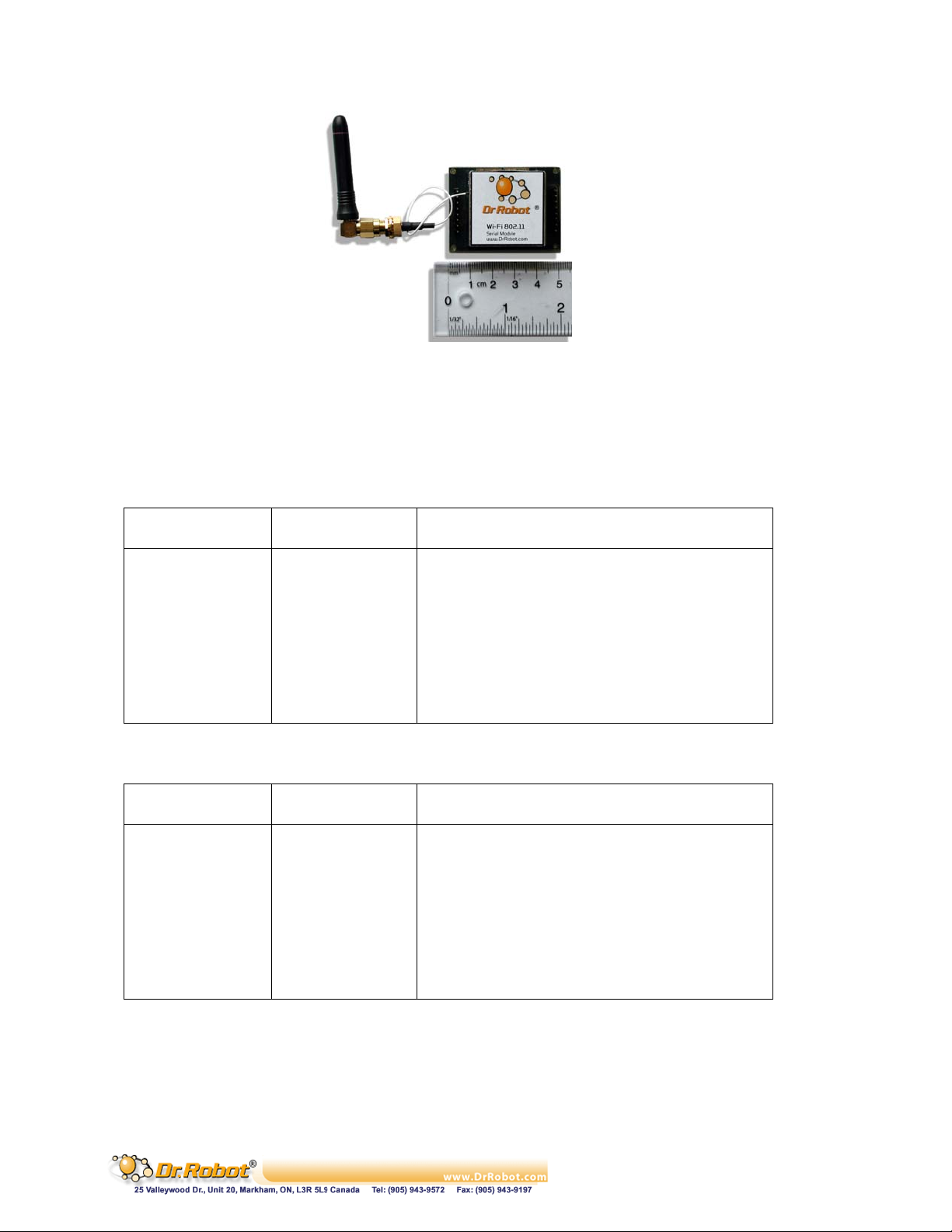
Figure IV.1 WFS802bStructure
IV.3.2 Connector Description
The WFS802b is connected to WiRobot system via an 8-pin 2.54 mm-pitch single row connector1
(COM1):
Table IV.1 Connector1 (COM1)
Pin Name Function
1 VCC +3.3 V
2 RXD Data receiving
3 TXD Data transmitting
4 RTS Request to send
5 CRTS Clear to send
6 GND Power supply ground
7 NC Reserved
8 NC Reserved
Table IV.2 Connector2 (COM2)
Pin Name Function
1 NC Reserved
2 RXD Data receiving
3 TXD Data transmitting
4 RTS Request to send
5 CRTS Clear to send
6 GND Power supply ground
7 NC Reserved
8 NC Reserved
Copyright © Dr Robot Inc. 2005
94
Page 96
IV.4 Specifications
Network Standard IEEE 802.11b
Frequency Range 2.412 – 2.484 GHz
Radio # of Selectable Channels 14 Channels
Security Password protection, locking features, WEP 64/128
Maximum Receive Level -10dBm (with PER < 8%)
Receiver Sensitivity . -82dBm for 11Mbps
WLAN Power and Link LED Current Max: 4mA
Firmware Upgradeable via serial port
Serial Interface CMOS (Asynchronous) 3.3V-level signals
Serial Line Formats 7 or 8 data bits, 1-2 Stop bits,
Modem Control DTR, DCD
Flow Control XON/XOFF (software), CTS/RTS (hardware), none
Network Interface Wireless 802.11b
Protocols Supported 802.11b, UDP, TCP, DHCP
Table IV.3 WFS802b Specification
. -87dBm for 5.5Mbps
. -89dBm for 2.0Mbps
. -93dBm for 1.0Mbps
Rate is software selectable (300 bps to 921600 bps)
Parity: odd, even, none
Data Rates With Automatic Fallback . 11Mbps
. 5.5Mbps
. 2Mbps
. 1Mbps
Media Access Control CSMA/CA with ACK
Frequency Range 2.412 – 2.484 GHz
Range Up to 328 feet indoors
Modulation Techniques . CCK (11Mbps)
. CCK (5.5 Mbps)
. DQPSK (2 Mbps)
. DBPSK (1 Mbps)
Transmit Output Power 14dBm ± 1dBm
Average Power Consumption . 1280 mW (WLAN mode; maximum data rate)
. 820 mW (WLAN mode; idle)
. 710 mW (Ethernet mode)
Peak Supply Current 460 mA
Management Internal web server
Weight with antenna 50 grams
Temperature Operating range, WLAN: -40°C to +70°C
Size (w/o antenna) 50 mm x 40 mm x 15 mm
Copyright © Dr Robot Inc. 2005
95
Page 97
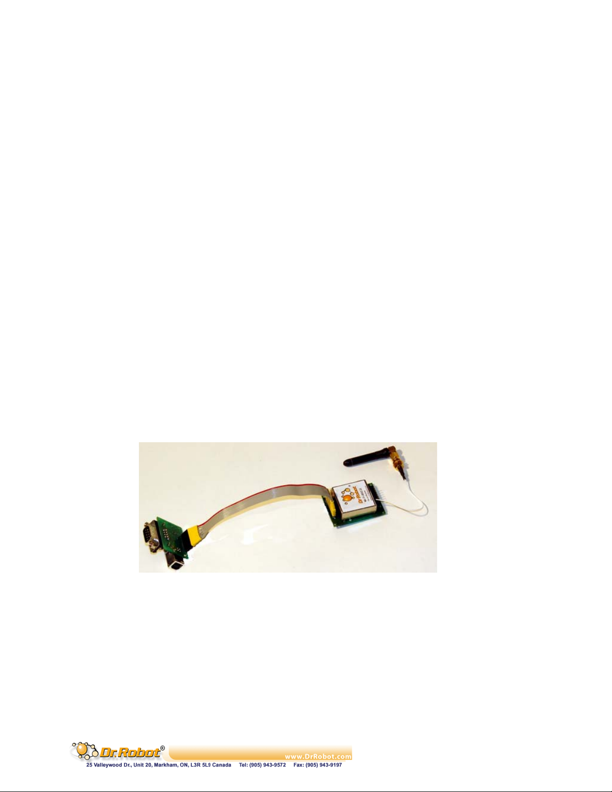
IV.5 Configuration via Serial Mode or Telnet Port
Configure the unit so that it can communicate on a network with your serial device.
The WFS802b unit is configurable using a terminal program to access the serial port locally. Using this
terminal program to respond to prompts is referred to as the Setup Mode. A Telnet connection may also be
used to configure the unit over the network.
The unit’s configuration is stored in nonvolatile memory and is retained without power. You can change the
configuration at any time. The unit performs a reset after the configuration has been changed and stored.
Note: The menus in this section show a typical device. Not all devices display information in the same
manner.
This chapter includes the following topics:
. Accessi
. Server
. Ch
. Email
WLAN Settings
.
. Ex
. Securi
Factory Defaults
.
. Exit
ng Setup Mode
Configuration
annel 1 and Channel 2 Configuration
Configuration
pert Settings
ty Settings
Configuration Mode
Figure IV.1 Connection WFS802b with MCR3210P RS232 Interface Module
Accessing Setup Mode
IV.5.1
Telnet Access
To configure the unit over the network, establish a Telnet connection to port 9999:
1. From the Windows Start menu, click Run.
2. From the Run dialogue box, type the following command (where x.x.x.x is the IP
Copyright © Dr Robot Inc. 2005
96
Page 98

address and 9999 is the unit’s fixed network configuration port number):
Windows: telnet x.x.x.x 9999
UNIX: telnet x.x.x.x:9999
3. Click OK. The following information displays:
Figure IV.1 MAC Address
MAC address 00204AFFFF30
Software version 05.3(040129)WPT
Press Enter to go into Setup Mode
4. To enter the Setup Mode, press Enter within 5 seconds.
Note: Connection fails if Enter is not pressed within 5 seconds.
The configuration settings display, followed by the setup menu options:
Figure IV.2 Setup Menu Options
Change Setup:
0 Server
1 Channel 1
2 Channel 2
3 Email
4 WLAN
5 Expert
6 Security
7 Factory defaults
8 Exit without save
9 Save and exit Your choice ?
5. Select an option on the menu by entering the number of the option in the Your
choice ? field and pressing Enter.
View the current configuration by pressing Enter from the Change Setup menu.
To enter a value for a parameter, type the value and press Enter. To confirm a
current value, press Enter (without inputted parameters).
6. When finished, save the new configurations (9 Save and exit). The unit reboots.
Serial Port Access
To configure the unit through a serial connection:
1. Connect a console terminal or PC running a terminal emulation program to your
unit's serial port. The default serial port settings are 9600 baud, 8 bits, no parity, 1
stop bit, no flow control.
2. Reset the WFS802b unit by cycling the unit's power (turning the power off and
back on). Immediately upon resetting the device, enter three lowercase x characters
Copyright © Dr Robot Inc. 2005
97
Page 99
(xxx).
Note: The easiest way to enter Setup Mode is to hold down the x key at the terminal
(or emulation) while resetting the unit. This must be done within three seconds of
resetting the WFS802b.
3. Upon connection, the following information displays:
Figure IV.3 MAC Address
MAC address 00204AFFFF30
Software version 05.3 (040129) WPT
Press Enter to go into Setup Mode
4. To enter the Setup Mode, press Enter within 5 seconds
Note: Connection fails if Enter is not pressed within 5 seconds.
The configuration settings display, followed by the setup menu options:
Figure IV.4 Setup Menu Options
Change Setup:
0 Server
1 Channel 1
2 Channel 2
3 Email
4 WLAN
5 Expert
6 Security
7 Factory defaults
8 Exit without save
9 Save and exit Your choice ?
5. Select an option on the menu by entering the number of the option in the Your choice ?
field and pressing Enter.
View the current configuration by pressing Enter from the Change Setup menu. To
enter a value for a parameter, type the value and press Enter. To confirm a current
value, press Enter (without inputted parameters).
6. When finished, save the new configurations (9 Save and exit). The unit reboots
Server Configuration
IV.5.2
The unit’s basic server (i.e. network) values display upon selecting Server (option 0 from the
Change Setup menu). The following sections describe the configurable parameters within the
Copyright © Dr Robot Inc. 2005
98
Page 100
Server configuration menu.
Set the IP Address
If DHCP is not used to assign IP addresses, enter it manually. The IP address must be set to a
unique value in the network. Enter each octet and press Enter between each section inputted.
The current value is displayed in parentheses.
IP Address : ( 0) ( 0) ( 0) ( 0)
Set the Gateway IP Address
The gateway address, or router, allows communication to other LAN segments. The
gateway address should be the IP address of the router connected to the same LAN
segment as the unit. The gateway address must be within the local network.
The default is N (No), indicating the gateway address has not been set. To set the gateway
address, type Y. At the prompt, enter the gateway address.
Set Gateway IP Address (N) ? Y
Gateway IP addr ( 0) ( 0) ( 0) ( 0)
Set the Netmask
A netmask defines the number of bits taken from the IP address that are assigned for the
host part.
Netmask: Number of Bits for Host Part (0=default) (0)
The unit prompts for the number of host bits to be entered, then calculates the netmask, which
displays in standard decimal-dot notation when the saved parameters are displayed (for
example, 255.255.255.0).
Table IV.4 Standard IP Network Netmasks Representing Host Bits
Network Class Host Bits Netmask
A 24 255.0.0.0
B 16 255.255.0.0
C 8 255.255.255.0
Change Telnet Configuration Password
Setting the Telnet configuration password prevents unauthorized access to the setup
menu via a Telnet connection to port 9999 or via web pages. The password must have
4 characters.
Change telnet config password (N) ?
An enhanced password setting (for Telnet access only) of 16 characters is available under
option 6 Security from the Change Setup menu.
Note: A password is not required to access the Setup Mode window via a serial
Copyright © Dr Robot Inc. 2005
99
 Loading...