

Page 1
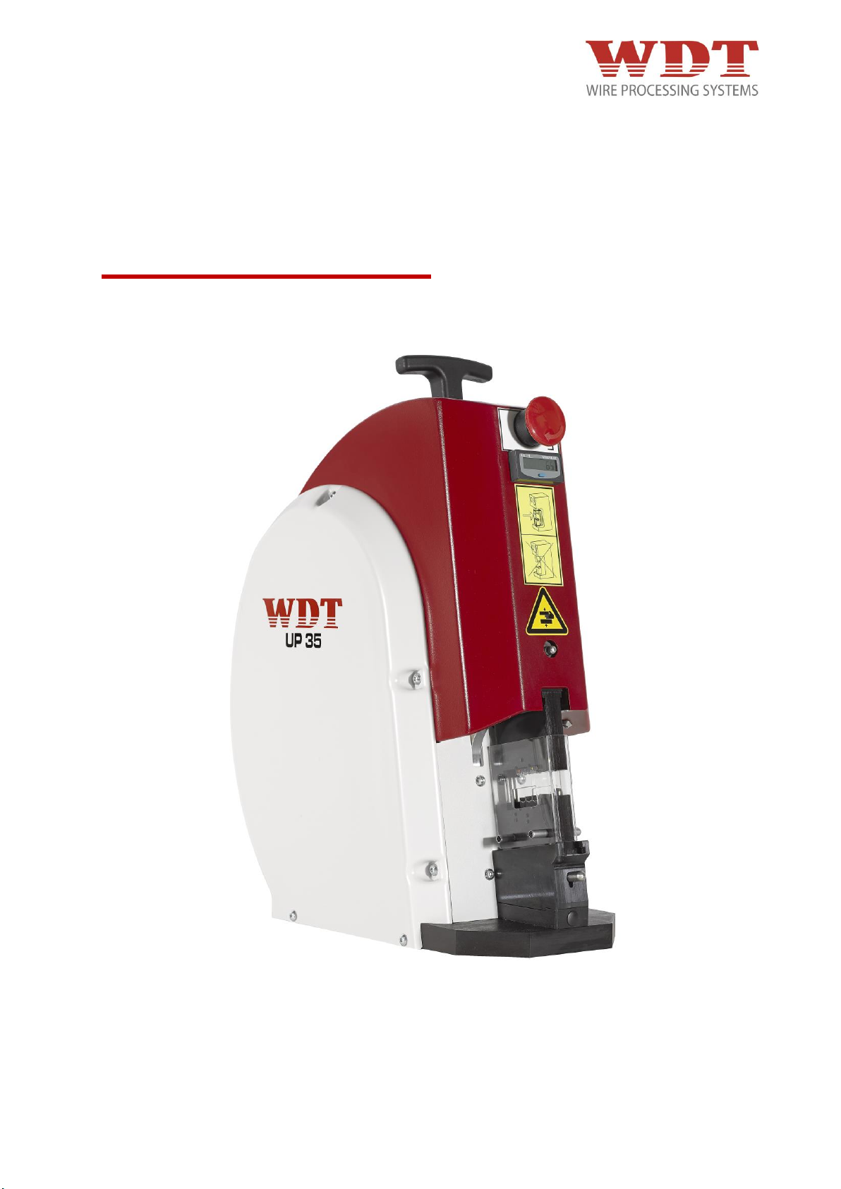
Pneumatische Crimpmaschine
Pneumatic Crimp Machine
Version UP 35 – 4481N26000 – 03/15 – REV.B1
MADE IN GERMANY
UP 35
Betriebsanleitung
Operating Instructions
Mode d’Emploi
a WEZAG brand
Page 2

Originalbetriebsanleitung
Hersteller / Producer
WEZAG GmbH
Werkzeugfabrik
Wittigstraße 8
35260 Stadtallendorf
Telefon: +49 6428 704-0
Ausgabedatum Version
01.02.2015 REV. 0
27.11.2015 REV. A
01.07.2016 REV. B
© by WEZAG GmbH
Der Nachdruck dieser Anleitung, auch auszugsweise, gleichgültig in welcher Form, ist ohne
ausdrückliche, schriftliche Genehmigung des Herausgebers verboten.
Gegenüber Darstellung und Angaben in dieser Anleitung sind technische Änderungen, die zur
Verbesserung der Maschine notwendig werden, vorbehalten.
Reproduction of these instructions or parts of them in whatever form is not permitted without
express written permission from the publisher.
We reserve the right to make technical changes necessary to improve the machine that could
diverge from figures and information in these instructions.
UP35-4481N26000-02/15 – REV.B1 Page 2 / 63
Page 3

Deutsche Version (Originalversion)
Inhaltsverzeichnis 4
English Version (Translation)
Table of contents 33
UP35-4481N26000-02/15 – REV.B1 Page 3 / 63
Page 4

Inhaltsverzeichnis
1 Einleitung ............................................................................................................................................. 5
1.1 Produktbeschreibung ..................................................................................................................... 5
1.2 Konformität ..................................................................................................................................... 6
1.3 Umgang mit der Betriebsanleitung ................................................................................................. 7
2 Sicherheit ............................................................................................................................................. 7
2.1 Hinweiserklärung ............................................................................................................................ 7
2.2 Allgemeine Sicherheitshinweise .................................................................................................... 8
2.3 Verantwortlichkeiten ....................................................................................................................... 9
2.4 Bestimmungsgemäße Verwendung ............................................................................................. 10
2.5 Vorhersehbare Fehlanwendung ................................................................................................... 10
2.6 Gefährdungsbereiche .................................................................................................................. 10
3 Lieferung ............................................................................................................................................ 11
3.1 Verpackung ................................................................................................................................. 11
3.2 Lieferumfang ................................................................................................................................ 11
4 Technische Beschreibung ............................................................................................................... 12
4.1 Funktions- und Bedienungselemente .......................................................................................... 12
4.2 Maschinenidentifikation ............................................................................................................... 13
4.3 Technische Daten ........................................................................................................................ 13
4.4 Schutzabdeckung......................................................................................................................... 13
4.5 Rückstell-Taster ........................................................................................................................... 13
5 Transport und Aufstellung ............................................................................................................... 14
5.1 Transport ...................................................................................................................................... 14
5.2 Aufstellung ................................................................................................................................... 14
6 Inbetriebnahme ................................................................................................................................. 15
6.1 Anschließen an das Druckluftnetz ............................................................................................... 15
6.2 Kontrolle der Crimphöhe .............................................................................................................. 17
7 Umrüsten ........................................................................................................................................... 18
7.1 Verfügbare Adapter ...................................................................................................................... 18
7.2 Montage der Adapter ................................................................................................................... 19
7.3 Montage der jeweiligen Gesenkpaare in den dafür vorgesehenen Adapter............................... 20
7.4 Montage der jeweiligen CSV 10-Werkzeugköpfe in den dafür vorgesehenen Adapter ............. 22
7.5 Montage der Adapter in Maschine ............................................................................................... 23
8 Normalbetrieb /Produktionsbetrieb ................................................................................................ 24
9 Instandhaltung .................................................................................................................................. 25
9.1 Wartungsplan ............................................................................................................................... 26
9.1.1 Täglich .................................................................................................................................. 26
9.1.2 Monatlich ............................................................................................................................... 27
9.1.3 Nach jeweils 25.000 Zyklen oder alle zwei Jahre ................................................................. 27
10 Fehlersuche und Störungsanalyse ................................................................................................. 28
11 Außerbetriebnahme, Abbau, Demontage ....................................................................................... 29
12 Lagerung ............................................................................................................................................ 29
13 Entsorgung ........................................................................................................................................ 29
14 Ersatzteilliste, Pneumatikschema ................................................................................................... 30
14.1 Explosionszeichnung ................................................................................................................... 30
14.2 Stückliste Explosionszeichnung ................................................................................................... 30
14.3 Pneumatik Schema ...................................................................................................................... 32
14.4 Stückliste Pneumatik Schema ..................................................................................................... 33
14.5 Zubehörübersicht für Nachbestellungen ...................................................................................... 33
UP35-4481N26000-02/15 – REV.B1 Page 4 / 63
Page 5

1 Einleitung
1.1 Produktbeschreibung
Die pneumatische Parallel Crimpmaschine UP 35 ist ein druckluftbetriebenes, als Tischgerät
konzipiertes Crimpgerät für das WEZAG Crimpwerkzeug-System. Die meisten
handelsüblichen Crimpkontakte werden mit der pneumatischen Parallel Crimpmaschine UP
35 und dem auswechselbaren WEZAG Crimpwerkzeug-System verarbeitet.
Passend zum Crimpkontakt wird ein geeignetes, auswechselbares Crimpgesenk mit
entsprechendem Adapter (inklusive Fingerschutz) in der pneumatischen Parallel
Crimpmaschine UP 35 montiert.
Durch das pneumatische Fußpedal wird der Crimpvorgang ausgelöst und der Crimpkontakt
verarbeitet. Die pneumatische Parallel Crimpmaschine UP 35 ist mit einer pneumatischen
Zwangsablaufsteuerung ausgerüstet und gewährleistet eine gleichbleibende Crimpqualität.
Sind die Crimpbacken durch einen Bedienungs- oder Handhabungsfehler oder durch
falsches Einlegen eines Crimpkontaktes blockiert, kann die pneumatische Parallel
Crimpmaschine UP 35 durch den Rückstell-Taster gelöst werden.
Jede andere Einsatzart der pneumatischen Parallel Crimpmaschine UP 35 ist nur mit
schriftlicher Zustimmung des Herstellers zulässig. Jede nicht bewilligte Einsatzart der
pneumatischen Parallel Crimpmaschine UP 35 gilt als nicht bestimmungsgemäß. Für daraus
resultierende Schäden lehnt der Hersteller jede Haftung ab.
UP35-4481N26000-02/15 – REV.B1 Page 5 / 63
Page 6
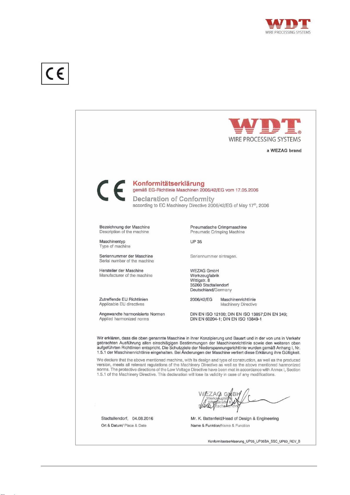
Abb. 1.1
1.2 Konformität
Die Maschine ist ausschließlich für den in der Betriebsanleitung beschriebenen Zweck zu
verwenden. Für Schäden, die aus nicht bestimmungsgemäßer Verwendung entstehen,
haftet der Hersteller bzw. Händler nicht: das Risiko hierfür trägt allein der Benutzer.
Die pneumatische Parallel Crimpmaschine UP 35 ist CE konform. Die folgende
Konformitätserklärung wurde im Original zusammen mit der Betriebsanleitung der
Maschine versendet.
UP35-4481N26000-02/15 – REV.B1 Page 6 / 63
Page 7
1.3 Umgang mit der Betriebsanleitung
Die Betriebsanleitung enthält alle Informationen über die Bedienungselemente,
Handhabung, Wartungs- und Einstellarbeiten sowie alle technischen Daten.
Die Betriebsanleitung muss ständig an der pneumatischen Parallel Crimpmaschine UP 35
verfügbar sein. Jeder der mit Arbeiten an der Maschine beauftragt ist, muss die
Betriebsanleitung gelesen und verstanden haben. Er muss während der Durchführung von
Arbeiten an oder mit der Maschine diese Betriebsanleitung beachten.
Der Hersteller sowie der Händler lehnen jede Haftung für Schäden ab, die durch
Nichtbeachten von Hinweisen auf der Maschine oder in der Betriebsanleitung entsteht.
Die Betriebsanleitung ist vom Benutzer der Maschine um Anweisungen aufgrund
bestehender nationaler Vorschriften zur Unfallverhütung und zum Umweltschutz zu
ergänzen.
Rechtsverbindlich ist die deutsche Originalfassung.
Die Betriebsanleitung ist für spätere Verwendung aufzubewahren.
2 Sicherheit
2.1 Hinweiserklärung
Auf die verschiedenen Gefahrenstufen wird in den einzelnen Abschnitten und Kapiteln mit
folgenden Sicherheitshinweisen aufmerksam gemacht:
GEFAHR
+ Kennzeichnet eine unmittelbar drohende, große Gefahr, die mit Sicherheit zu
schweren Verletzungen oder sogar zum Tode führt, wenn die Gefahr nicht umgangen
wird.
WARNUNG
+ Kennzeichnet eine mögliche Gefahr, die zu schweren Verletzungen oder sogar zum
Tode führt, wenn die Gefahr nicht umgangen wird.
VORSICHT
+ Weist auf eine potenziell gefährliche Situation hin, die zu mittleren oder leichten
Körperverletzungen oder zu Sachschäden führen kann, wenn sie nicht umgangen wird.
HINWEIS
+ Wenn diese Information nicht beachtet wird, kann dies zu Verschlechterungen im
Betriebsablauf führen.
UP35-4481N26000-02/15 – REV.B1 Page 7 / 63
Page 8

2.2 Allgemeine Sicherheitshinweise
Die pneumatische Parallel Crimpmaschine UP 35 ist nach dem Stand der Technik und den
anerkannten sicherheitstechnischen Regeln gebaut.
Beim Ausführen von Arbeiten wie Aufstellen, Inbetriebnahme, Einrichten, Betreiben, Ändern
der Einsatzbedingungen und Betriebsweisen, Warten und Instandhalten der Maschine, sind
die in der Betriebsanleitung vorgeschriebenen Ausschaltprozeduren zu beachten.
Für den Betrieb der pneumatischen Parallel Crimpmaschine UP 35 sind die nationalen
Regelungen über das gesetzliche Mindestalter zu beachten. Es ist strikt untersagt, jüngeren
Personen Zutritt zu der pneumatischen Parallel Crimpmaschine UP 35 zu gewähren.
+ Betreiben Sie die pneumatische Parallel Crimpmaschine UP 35 nicht, bevor Sie alle
Anweisungen gelesen und verstanden haben.
+ Die pneumatische Parallel Crimpmaschine UP 35 darf nur in trockenen, staubfreien
Räumen, sowie in einem vollständigen und funktionsfähigen Zustand betrieben werden.
+ Ändern Sie die pneumatische Parallel Crimpmaschine UP 35 nicht ab und setzen Sie sie
nur für den vorgesehenen Verwendungszweck ein.
+ Für den Transport muss ein ausreichend dimensioniertes Hebezeug verwendet werden.
+ Zum Transport von Hand ist ein T-Griff an der Maschine angebracht. Tragen Sie beim
Transport der Maschine geeignete Sicherheitsschuhe.
+ Stellen Sie die Crimpmaschine auf einer ebenen Fläche auf und sorgen Sie für
Standfestigkeit der Crimpmaschine. Stellen Sie sicher, dass die Fläche stark genug ist,
um das Gewicht der Maschine bei normaler Benutzung aufnehmen zu können. Während
des Betriebs muss die Maschine auf einem Tisch oder einer ähnlichen Ebene stehen.
+ Sorgen Sie für eine geeignete Tischhöhe. Die Tischhöhe ist abhängig von der Position
des Bedienungspersonals (Arbeiten in der Sitzposition oder im Stehen), gemäß prEN
894-4:2004 Tabelle A.1, anzupassen.
+ Sorgen Sie für eine ausreichende Beleuchtung des Arbeitsplatzes (EN 1837:1999 –
Kapitel 4.2: „Im Allgemeinen muss der Wartungswert der Beleuchtungsstärke mindestens
500 lx betragen […]“.
+ Pneumatische Versorgung mit mitgeliefertem Druckluftschlauch (Schlauchlänge 1 Meter)
anschließen.
+ Der Druckluftanschluss darf eine Schlauchlänge von 1 Meter nicht überschreiten und
muss über einen Kupplungsanschluss verfügen.
+ Verlegen Sie so die Schläuche und Kabel am Boden, dass sie keine Stolpergefahr bilden.
+ Schläuche dürfen nicht beschädigt werden.
+ Das Fußpedal muss auf den Boden gestellt werden. Jede andere Platzierung des
Fußpedals als auf dem Fußboden ist untersagt.
+ Fußpedal nicht in Verkehrswegen verlegen!
+ Der Zugang zu den Stellteilen der Maschine muss frei gehalten werden. Dies gilt
insbesondere für das Fußpedal und den Rückstell-Taster. Betätigen Sie bei drohender
Gefahr den Rückstell-Taster sofort. Der Rückstell-Taster muss vom Bediener jederzeit
direkt zugänglich bleiben. Er darf nicht verdeckt werden!
+ Vor Beginn von Wartungs-, Demontage- und Instandhaltungsarbeiten muss die
pneumatische Parallel Crimpmaschine UP 35 sicher von der pneumatischen Versorgung
getrennt sein.
+ Instandhaltungsarbeiten dürfen nur von berechtigten und für diese Tätigkeit
ausgebildeten Personen ausgeführt werden. Insbesondere das Gehäuse und die
Abdeckungen dürfen nur von fachkundigem Personal entfernt werden.
+ Es besteht die Restgefahr des Quetschens von Fingern. Versuchen Sie nie in die
Gefahrenstelle zu greifen, ohne dass die Maschine sicher von der pneumatischen
Versorgung getrennt wurde. Unterbrechen Sie die pneumatische Versorgung, bevor Sie
die Schutzabdeckung, den Gesenkadapter und das Gesenkpaar auswechseln.
+ Vor jeder Inbetriebnahme ist zu prüfen, ob alle Sicherheitsvorrichtungen, insbesondere
Schutzabdeckung und Gesenkadapter, angebracht sind und einwandfrei funktionieren.
UP35-4481N26000-02/15 – REV.B1 Page 8 / 63
Page 9

+ Prüfen Sie die Funktionsfähigkeit des Rückstell- Tasters vor Beginn Ihrer Arbeit an der
Crimpmaschine. Betätigen Sie bei drohender Gefahr sofort den Rückstell-Taster. Der
Rückstell-Taster muss vom Bediener jederzeit direkt zugänglich bleiben. Er darf nicht
verdeckt werden!
+ Bei eingeschalteter pneumatischer Parallel Crimpmaschine UP 35 ist allgemein Vorsicht
geboten.
+ Die Maschine darf ausschließlich mit montiertem Gesenkpaar, Gesenkadapter und der
dazugehörigen Schutzeinrichtung betrieben werden. Zuordnung von Gesenkadapter und
Schutzabdeckung beachten!
+ Die pneumatische Parallel Crimpmaschine UP 35 darf nur in technisch einwandfreiem
Zustand, sowie sicherheits- und gefahrenbewusst eingerichtet und betrieben werden.
+ Bei Feststellung von Mängeln an der Maschine muss die Arbeit unterbrochen und die
Störung behoben werden, bevor weiter mit der Maschine gearbeitet wird.
+ Arbeiten Sie sorgfältig.
+ Es darf nur eine Person an oder mit der Maschine tätig sein.
+ Es darf nur geschultes Personal an der Maschine tätig werden.
+ Es darf nur mit dem angegebenen Betriebsdruck gearbeitet werden.
+ Tragen Sie beim Arbeiten mit der pneumatischen Parallel Crimpmaschine UP 35 keine
lose Kleidung, losen Schmuck oder lange, offene Haare, welche sich in den Teilen der
pneumatischen Parallel Crimpmaschine UP 35 verfangen können.
+ Trennen Sie die pneumatische Parallel Crimpmaschine UP 35 vom Druckluftnetz, bevor
Sie irgendwelche Wartungs- und Demontagearbeiten vornehmen. Es besteht die
Restgefahr des Quetschens von Fingern. Versuchen Sie nie in das Werkzeug zu greifen,
ohne dass die Maschine sicher von der pneumatischen Versorgung getrennt wurde.
+ Die Maschine ist nur durch die Hauptluftzufuhr Air Max komplett drucklos zu machen.
+ Bei Wartungsarbeiten an der Maschine sind geeignete Schutzhandschuhe und
Schutzbrille zu tragen. Beachten Sie die Sicherheitshinweise im „Sicherheitsblatt“ des
Schmierfettes bzw. Öls.
+ Tragen Sie beim Transport der Maschine geeignete Sicherheitsschuhe.
2.3 Verantwortlichkeiten
Die pneumatische Parallel Crimpmaschine UP 35 darf nur von ausgebildetem und
autorisiertem Personal betrieben werden. Die Zuständigkeit des Personals für Bedienen,
Rüsten, Warten und Instandhalten ist vom Benutzer der Maschine klar festzulegen und
einzuhalten. Insbesondere ist die Zuständigkeit für Arbeiten an der pneumatischen
Ausrüstung festzulegen. Solche Arbeiten bleiben nur ausgebildeten Fachleuten vorbehalten.
Eigenmächtige Veränderungen an der Maschine schließen eine Haftung des Herstellers
bzw. Händles für daraus resultierende Schäden aus.
Der Betreiber der pneumatischen Parallel Crimpmaschine UP 35 trägt die Verantwortung,
dass jede Person, die sich mit der Installation oder der Instandhaltung der Maschine befasst,
anhand der vorliegenden Betriebsanleitung genauestens instruiert worden ist.
Der Betreiber der pneumatischen Parallel Crimpmaschine UP 35 trägt ferner die
Verantwortung für die Ausbildung des Bedienpersonals, welche folgende Punkte beinhalten
muss:
+ Verwendungszweck der Maschine
+ Gefährdungsbereich
+ Sicherheitsbestimmungen
+ Funktion der verschiedenen Elemente der Maschine
+ Bedienung der Maschine
UP35-4481N26000-02/15 – REV.B1 Page 9 / 63
Page 10
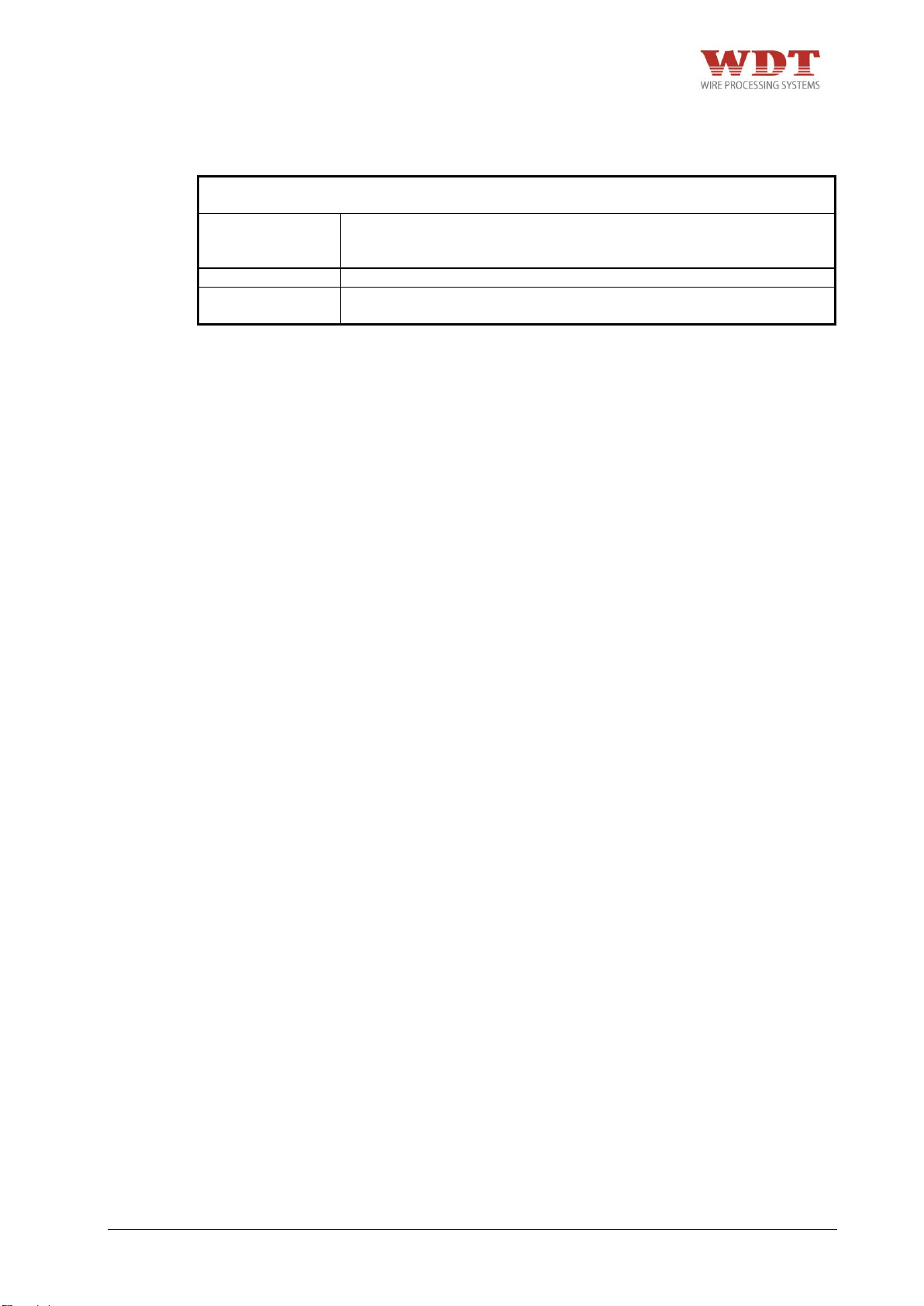
Notwendige Qualifikation der Personen, die mit dem Einsatz der pneumatischen
Parallel Crimpmaschine UP 35 miteinbezogen werden:
Montage
Inbetriebnahme
Instruktion
Technische Fachkräfte, die nebst der deutschen und englischen
Sprache, die Sprache des Bedienpersonals beherrschen.
Bedienung
Durch technische Fachkräfte geschulte, qualifizierte Personen.
Unterhalt
Service
Technische Fachkräfte, die Deutsch oder Englisch beherrschen.
Um zu gewährleisten, dass die Einweisung und Instruktion der Maschine verstanden worden
ist, muss die Schulung in der Sprache des Bedienpersonals erfolgen.
Die Sicherheitsvorschriften und die einschlägigen Hinweise in den einzelnen Abschnitten
müssen durch die Betreiber und das Bedienpersonal zwingend eingehalten werden!
2.4 Bestimmungsgemäße Verwendung
+ Zum Herstellen von Crimpverbindungen bis zu einem Leitungsquerschnitt von max. 50
mm² in Abhängigkeit der Kontaktausführung.
Die pneumatische Parallel Crimpmaschine UP 35 ist zur Aufnahme der in Kapitel 7
dargestellten Adapter konzipiert. Der Adapter darf nur mit den WEZAG spezifizierten
Crimpgesenken bestückt werden. Die pneumatische Parallel Crimpmaschine UP 35 in
Verbindung mit Adapter, Fingerschutz und Crimpgesenke dürfen nur zur Herstellung von
Crimpverbindungen verwendet werden!
2.5 Vorhersehbare Fehlanwendung
+ Alle Anwendungen - außer den in Kapitel 2.4 „Bestimmungsgemäße Verwendung“
angegebenen.
2.6 Gefährdungsbereiche
1. Gefährdungsbereich: Bereich der auswechselbaren Crimpgesenke
Gefährdete Person: Bedienpersonal
Art der Gefährdung: Quetschgefahr
2. Gefährdungsbereich: Geöffnete Maschine
Gefährdete Person: Einrichter
Art der Gefährdung: direkter / indirekter Kontakt mit beweglichen Teilen der Maschine,
Schnittgefahr
Quetschgefahr
UP35-4481N26000-02/15 – REV.B1 Page 10 / 63
Page 11
1 Stk.
Pneumatische Parallel Crimpmaschine UP 35 mit Stückzähler und
Betriebsanleitung (ohne Gesenkadapter und Gesenkpaar)
1 Stk.
Eingriffschutz
1 Stk.
Pneumatisches Fußpedal mit Schutzhaube
1 Stk.
6-kant Stiftschlüssel 2,0 mm
1 Stk.
6-kant Stiftschlüssel 2,5 mm
1 Stk.
Fett-Stoßdruckpresse
1 Stk.
PU Druckluftschlauch Ø 8/6 mm à 1 Meter
1 Stk.
PU Druckluftschlauch Ø 6/4 mm à 2 Meter
1 Stk.
PU Druckluftschlauch Ø 4/2 mm à 2 Meter
1 Stk.
T-Griff
1 Stk.
Steckernetzteil 12 Volt mit Wechseladapter für EU/US/UK/AU
1 Stk.
Konformitätserklärung
Abb. 3.1
3 Lieferung
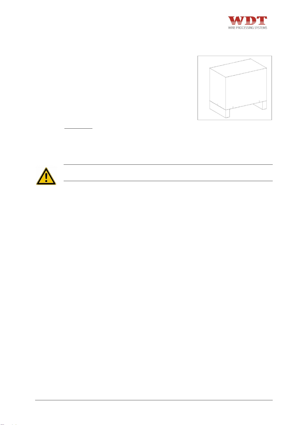
3.1 Verpackung
Packen Sie die Bauteile der pneumatischen
Parallel Crimpmaschine UP 35 sorgfältig aus
und überprüfen Sie den Lieferumfang mit
den Dokumenten (Lieferschein,
Konformitätserklärung, Betriebsanleitung).
Bewahren Sie die Original-Verpackung für
einen späteren Versand und für die
Lagerung der Maschine auf.
Abmessung:
Länge: 560 mm
Breite: 350 mm
Höhe: 610 mm
Gesamtgewicht: ca. 35 kg
GEFAHR
+ Für den Transport muss ein ausreichend dimensioniertes Hebezeug verwendet werden.
3.2 Lieferumfang
UP35-4481N26000-02/15 – REV.B1 Page 11 / 63
Page 12
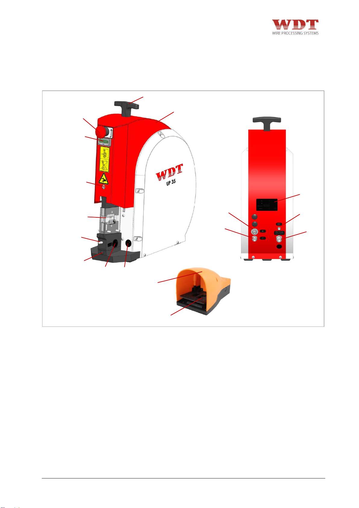
Pos.
Bezeichnung
01
Pneumatische Parallel Crimpmaschine UP 35
02
T-Griff
03
Rückstell-Taster
04
Stückzähler
05
Schmiernippel
06
Adapter CS 30/CK 100 für UP 35 (nicht im Lieferumfang enthalten)
07
Entriegelung für Adaptermontage
08
Verstellschraube (Höhe)
09
Spaltmaßangabe für Grundeinstellung
10
Lichtschalter
11
A = Steuerdruck
12
P = Druckluft (Fußpedal)
13
DC = Gleichstromanschluss (Licht)
14
Air max. = Druckluft
15
Typenschild mit Seriennummer
16
Pneumatisches Fußpedal
17
Fußpedal-Schutzhaube
01
03
16
17
02
04
05
06
07
08
09
10
11
12
13
14
15
Abb. 4.1
4 Technische Beschreibung
4.1 Funktions- und Bedienungselemente
UP35-4481N26000-02/15 – REV.B1 Page 12 / 63
Page 13
Abmessung:
Länge:
390 mm
Breite:
175 mm
Höhe:
440 mm
Gewicht mit Fußpedal:
ca. 25 kg
Betriebsdruckluft:
6 bar
Luftverbrauch pro Hub:
2,3 l
Crimpkraft bei 6 bar:
max. 35 kN
Öffnungsmaß:
ca. 18 mm
Lärmpegel:
62 dB(A)
Pos.
Bezeichnung
1
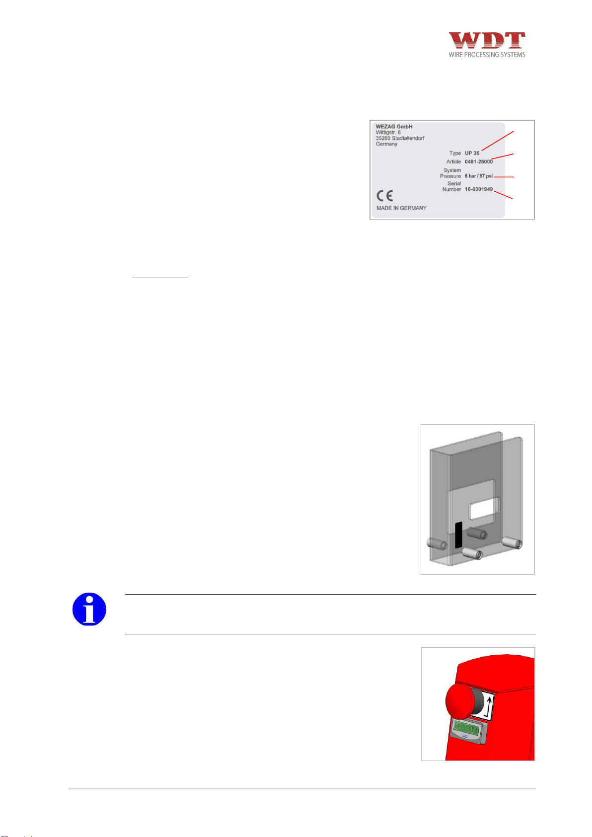
Maschinentyp
2
Artikelnummer
3
Betriebsdruck
4
Seriennummer
Abb. 4.3
Abb. 4.4
Abb. 4.2
1
2
3
4
4.2 Maschinenidentifikation
4.3 Technische Daten
4.4 Schutzabdeckung
Jeder Gesenkadapter verfügt über eine auf
ihn speziell abgestimmte Schutzabdeckung
(im Lieferumfang des Gesenkadapters
enthalten).
Gesenkadapter und die entsprechenden
Schutzabdeckungen finden Sie in Kapitel 7!
HINWEIS
+ Bei Unfällen, verursacht durch Entfernen/Manipulieren der Schutzabdeckung, haftet der
Hersteller nicht.
4.5 Rückstell-Taster
Ist der Gesenkadapter durch einen
Bedienungs- oder Handhabungsfehler oder
falsches Einlegen eines Crimpkontaktes
blockiert, wird die pneumatische Parallel
Crimpmaschine UP 35 wie folgt gelöst:
UP35-4481N26000-02/15 – REV.B1 Page 13 / 63
+ Betätigen Sie den Rückstell-Taster.
Page 14
5 Transport und Aufstellung
5.1 Transport
Das Gewicht der pneumatischen Parallel Crimpmaschine beträgt ca. 20 kg.
Montieren Sie den im Lieferumfang enthaltenen T-Griff auf die Maschine.
WARNUNG
+ Zum Transport den T-Griff verwenden.
VORSICHT
+ Schläuche dürfen nicht beschädigt werden.
+ Tragen Sie beim Transport und beim Aufstellen der pneumatischen Parallel
Crimpmaschine UP 35 geeignete Sicherheitsschuhe.
HINWEIS
+ Zum Transport von Hand ist ein T-Griff im Lieferumfang enthalten, der auf der Maschine
angebracht wird.
5.2 Aufstellung
VORSICHT
+ Stellen Sie die Crimpmaschine auf einer ebenen Fläche auf und sorgen Sie für
Standfestigkeit der Crimpmaschine. Stellen Sie sicher, dass die Fläche stark genug ist,
um das Gewicht der Maschine bei normaler Benutzung aufnehmen zu können.
+ Sorgen Sie für eine geeignete Tischhöhe. Die Tischhöhe ist, abhängig von der Position
des Bedienpersonals (Arbeiten in der Sitzposition oder im Stehen), gemäß prEN 8944:2004 Tabelle A.1, anzupassen.
+ Sorgen Sie für eine ausreichende Beleuchtung des Arbeitsplatzes (EN 1837:1999 –
Kapitel 4.2: „Im Allgemeinen muss der Wartungswert der Beleuchtungsstärke mindestens
500 lx betragen [...] " ).
HINWEIS
+ Um das Betriebsgeräusch zu vermindern, können Sie die Crimpmaschine auf eine
rutschfeste Gummiunterlage stellen.
Stellen Sie das Fußpedal auf den Fußboden. Jede andere Platzierung des Fußpedals als
auf dem Fußboden ist untersagt!
VORSICHT
+ Verlegen Sie so die Schläuche am Boden, dass sie keine Stolpergefahr bilden.
+ Fußpedal nicht in Verkehrswegen verlegen!
+ Der Zugang zu den Stellteilen der Maschine muss frei gehalten werden. Dies gilt
insbesondere für das Fußpedal und den Rückstell-Taster.
+ Tragen Sie beim Transport und bei der Aufstellung der Maschine geeignete
Sicherheitsschuhe.
HINWEIS
+ Zum ermüdungsfreien Arbeiten muss von dem Bediener eine Arbeitsposition
eingenommen werden, die neben der korrekten Höhenpositionierung zur Maschine, auch
ein einwandfreies Betätigen des Fußpedals zulässt. Hierbei ist darauf zu achten, dass
das Fußpedal standfest installiert ist. Die Position des Fußpedals sollte so ausgewählt
werden, dass dieses einwandfrei zu bedienen und leicht zugänglich ist.
UP35-4481N26000-02/15 – REV.B1 Page 14 / 63
Page 15
6 Inbetriebnahme
6.1 Anschließen an das Druckluftnetz
GEFAHR
+ Es besteht die Restgefahr des Quetschens von Fingern. Versuchen Sie nie, in die
Gefahrenstelle zu greifen, ohne dass die Maschine sicher von der pneumatischen
Versorgung getrennt wurde. Unterbrechen Sie die pneumatische Versorgung, bevor Sie
die Schutzabdeckung, den Gesenkadapter und das Gesenkpaar auswechseln.
WARNUNG
+ Die pneumatische Parallel Crimpmaschine UP 35 darf nur in technisch einwandfreien
Zustand, sowie sicherheits- und gefahrenbewusst eingerichtet und betrieben werden.
+ Die Crimpmaschine darf nur bei montierten Gesenkadapter, Gesenkpaar und der
dazugehörigen Schutzeinrichtung betrieben werden. Zuordnung von Gesenkadapter und
Schutzabdeckung beachten!
+ Die Crimpmaschine darf nur in einem vollständigen und funktionsfähigen Zustand
betrieben werden.
+ Tragen Sie beim Arbeiten mit der pneumatischen Parallel Crimpmaschine UP 35 keine
lose Kleidung, losen Schmuck oder lange, offene Haare, welche sich in den Teilen der
pneumatischen Parallel Crimpmaschine UP 35 verfangen können.
+ Arbeiten Sie sorgfältig.
+ Bei Feststellung von Mängeln an der Maschine muss die Arbeit unterbrochen und die
Störung behoben werden, bevor weiter mit der Maschine gearbeitet wird.
+ Es darf nur eine Person an oder mit der Maschine tätig sein.
+ Es darf nur geschultes Personal an der Maschine tätig werden.
+ Der Zugang zu den Stellteilen der Maschine muss frei gehalten werden. Es gilt
insbesondere für das Fußpedal und den Rückstell-Taster. Betätigen Sie bei drohender
Gefahr den Rückstell-Taster sofort. Der Rückstell-Taster muss vom Bediener jederzeit
direkt zugänglich bleiben. Er darf nicht verdeckt werden!
+ Es darf nur mit dem angegebenen Betriebsdruck gearbeitet werden.
UP35-4481N26000-02/15 – REV.B1 Page 15 / 63
Page 16
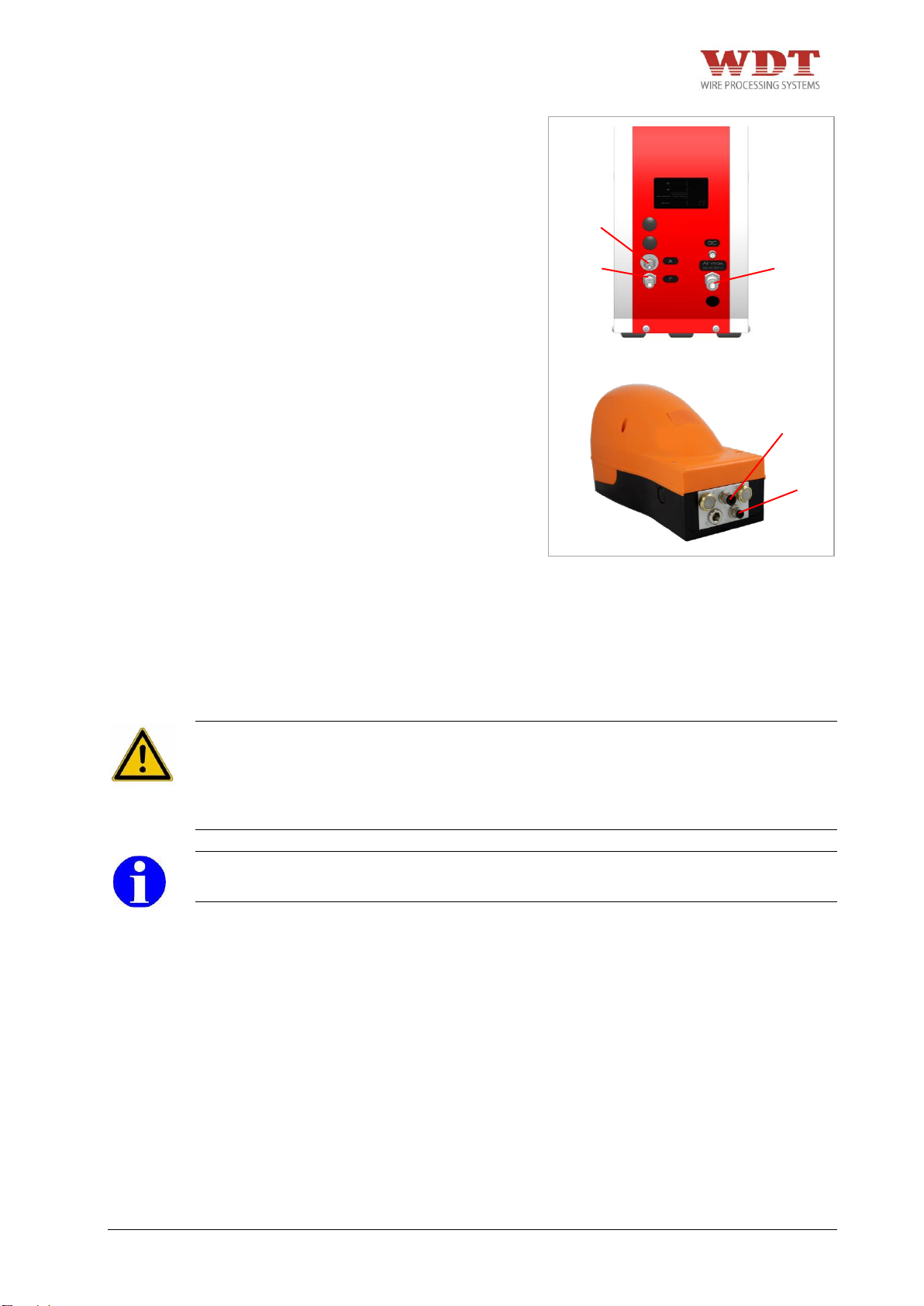
4 1 A
P
Air
MAX
Abb. 6.1
Pneumatischer Fußpedalanschluss 1 mit
Verschraubung P an der Maschine
verbinden. (PU Druckluftschlauch Ø 6/4mm).
Steuerleitung von pneumatischem Fußpedal
4 an Verschraubung A an der Maschine
montieren.
(PU Druckluftschlauch Ø 4/2mm).
Die pneumatische Parallel Crimpmaschine UP 35 nur mit aufbereiteter (geölter und
gereinigter) Druckluft betreiben. Standardfilter: 30 µm.
Anschluss Air MAX. (Abb. 6.1) der pneumatischen Parallel Crimpmaschine UP 35 mit
Druckluftschlauch Ø 8/6 mm mit dem Druckluftnetz verbinden.
Betriebsdruck: 6 bar.
WARNUNG
+ Pneumatische Versorgung mit mitgeliefertem Druckluftschlauch (Schlauchlänge 1 Meter)
anschließen.
+ Die Maschine ist nur durch die Hauptluftzuleitung Air MAX. (Abb. 6.1) komplett drucklos
zu machen.
HINWEIS
+ Nur aufbereitete (geölte und gereinigte) Druckluft verwenden.
UP35-4481N26000-02/15 – REV.B1 Page 16 / 63
Page 17
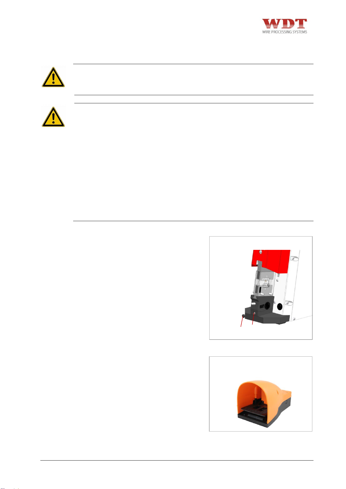
1
2
Abb. 6.2
Abb. 6.3
6.2 Kontrolle der Crimphöhe
GEFAHR
+ Es besteht die Restgefahr des Quetschens von Fingern. Versuchen Sie nie in die
Gefahrenstelle zu greifen, ohne dass die Maschine sicher von der pneumatischen
Versorgung getrennt wurde.
WARNUNG
+ Die Crimpmaschine darf nur bei montierten Gesenkadapter, Gesenkpaar und der
dazugehörigen Schutzeinrichtung betrieben werden. Zuordnung von Gesenkadapter und
Schutzabdeckung beachten!
+ Die Crimpmaschine darf nur in einem vollständigen und funktionsfähigen Zustand
betrieben werden.
+ Tragen Sie beim Arbeiten mit der pneumatischen Parallel Crimpmaschine UP 35 keine
lose Kleidung, losen Schmuck oder lange, offene Haare, welche sich in den Teilen der
pneumatischen Parallel Crimpmaschine UP 35 verfangen können.
+ Arbeiten Sie sorgfältig.
+ Bei Feststellung von Mängeln an der Maschine muss die Arbeit unterbrochen und die
Störung behoben werden, bevor weiter mit der Maschine gearbeitet wird.
+ Es darf nur eine Person an oder mit der Maschine tätig sein.
+ Es darf nur geschultes Personal an der Maschine tätig werden.
+ Es darf nur mit dem angegebenen Betriebsdruck gearbeitet werden.
+ Abdeckung 1 vor der Verstellschraube 2
abziehen.
+ Verstellschraube 2 lösen (gegen den
Uhrzeigersinn).
+ Fußpedal drücken und halten.
+ Verstellschraube 2 anziehen (im
Uhrzeigersinn).
+ Fußpedal wieder loslassen. Sollte sich
die Crimpmaschine nicht öffnen, muss
der Rückstell-Taster gedrückt werden.
UP35-4481N26000-02/15 – REV.B1 Page 17 / 63
Page 18
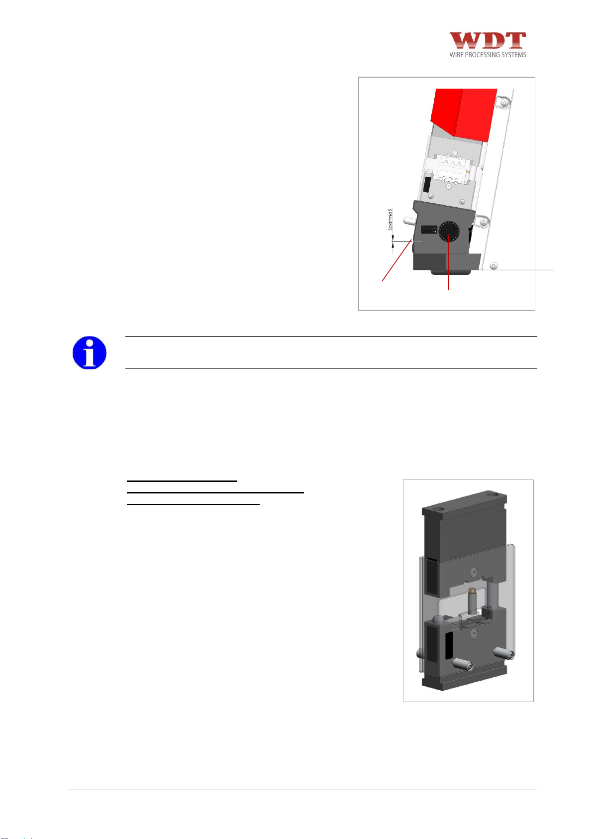
3
4
Abb. 6.4
Abb. 7.1
+ Verstellschraube 2 wieder lösen und den
Vorgang von oben wiederholen.
+ Verstellschraube 2 ca. 1/4-Drehung
nachstellen.
+ Spaltmaß 3 der Verstelleinheit
gegebenenfalls mit Spaltmaßangaben 4
abgleichen.
HINWEIS
+ Rückstell-Taster sofort drücken, wenn die beiden Gesenkhälften nicht übereinstimmen.
7 Umrüsten
7.1 Verfügbare Adapter
Adapter CS 30 / CK 100
Inklusive Schutzabdeckung für UP 35
WEZAG Art.-Nr. 1481-06010
UP35-4481N26000-02/15 – REV.B1 Page 18 / 63
Page 19
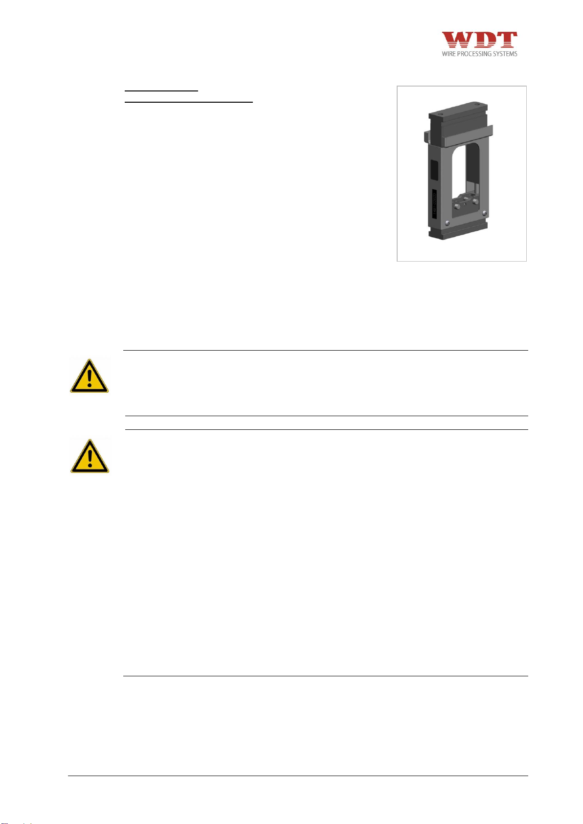
Abb. 7.2
Adapter CSV 10
WEZAG Art.-Nr. 1481-06022
7.2 Montage der Adapter
GEFAHR
+ Es besteht die Restgefahr des Quetschens von Fingern. Versuchen Sie nie, in die
Gefahrenstelle zu greifen, ohne dass die Maschine sicher von der pneumatischen
Versorgung getrennt wurde. Unterbrechen Sie die pneumatische Versorgung, bevor Sie
die Schutzabdeckung, den Gesenkadapter und das Gesenkpaar auswechseln.
WARNUNG
+ Die Crimpmaschine darf nur bei montierten Gesenkadapter, Gesenkpaar und der
dazugehörigen Schutzeinrichtung betrieben werden. Zuordnung von Gesenkadapter und
Schutzabdeckung beachten!
+ Die Crimpmaschine darf nur in einem vollständigen und funktionsfähigen Zustand
betrieben werden.
+ Vor jeder Inbetriebnahme ist zu prüfen, ob alle Sicherheitsvorrichtungen, insbesondere
Schutzabdeckungen und Gesenkadapter, angebracht sind und einwandfrei funktionieren.
+ Tragen Sie beim Arbeiten mit der pneumatischen Parallel Crimpmaschine UP 35 keine
lose Kleidung, losen Schmuck oder lange, offene Haare, welche sich in den Teilen der
pneumatischen Parallel Crimpmaschine UP 35 verfangen können.
+ Arbeiten Sie sorgfältig.
+ Es darf nur eine Person an oder mit der Maschine tätig sein.
+ Es darf nur geschultes Personal an oder mit der Maschine tätig sein.
+ Der Zugang zu den Stellteilen der Maschine muss frei gehalten werden. Es gilt
insbesondere für das Fußpedal und den Rückstell-Taster. Betätigen Sie bei drohender
Gefahr den Rückstell-Taster sofort. Der Rückstell-Taster muss vom Bediener jederzeit
direkt zugänglich bleiben. Er darf nicht verdeckt werden!
+ Es darf nur mit dem angegebenen Betriebsdruck gearbeitet werden.
UP35-4481N26000-02/15 – REV.B1 Page 19 / 63
Page 20
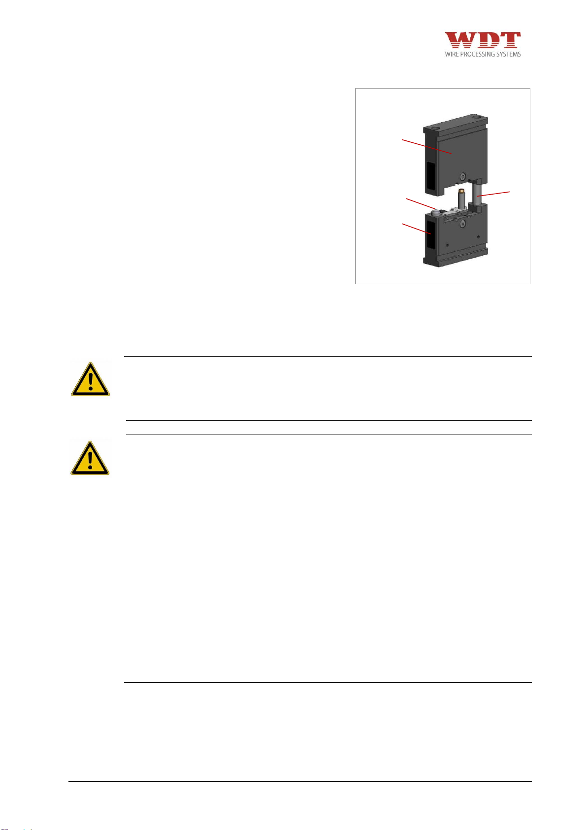
1 3 3
2
Abb. 7.3
+ Der Gesenkadapter oben 1 wird über die
Führungsbolzen 3 auf den GesenkAdapter unten 2 zentriert aufgeschoben.
7.3 Montage der jeweiligen Gesenkpaare in den dafür vorgesehenen
Adapter
GEFAHR
+ Es besteht die Restgefahr des Quetschens von Fingern. Versuchen Sie nie, in die
Gefahrenstelle zu greifen, ohne dass die Maschine sicher von der pneumatischen
Versorgung getrennt wurde. Unterbrechen Sie die pneumatische Versorgung, bevor Sie
die Schutzabdeckung, den Gesenkadapter und das Gesenkpaar auswechseln.
WARNUNG
+ Die Crimpmaschine darf nur bei montierten Gesenkadapter, Gesenkpaar und der
dazugehörigen Schutzeinrichtung betrieben werden. Zuordnung von Gesenkadapter und
Schutzabdeckung beachten!
+ Die Crimpmaschine darf nur in einem vollständigen und funktionsfähigen Zustand
betrieben werden.
+ Vor jeder Inbetriebnahme ist zu prüfen, ob alle Sicherheitsvorrichtungen, insbesondere
Schutzabdeckungen und Gesenkadapter, angebracht sind und einwandfrei funktionieren.
+ Tragen Sie beim Arbeiten mit der pneumatischen Parallel Crimpmaschine
UP 35 keine lose Kleidung, losen Schmuck oder lange, offene Haare, welche sich in den
Teilen der pneumatischen Parallel Crimpmaschine UP 35 verfangen können.
+ Arbeiten Sie sorgfältig.
+ Es darf nur eine Person an oder mit der Maschine tätig sein.
+ Es darf nur geschultes Personal an oder mit der Maschine tätig sein.
+ Der Zugang zu den Stellteilen der Maschine muss frei gehalten werden. Es gilt
insbesondere für das Fußpedal und den Rückstell-Taster. Betätigen Sie bei drohender
Gefahr den Rückstell-Taster sofort. Der Rückstell-Taster muss vom Bediener jederzeit
direkt zugänglich bleiben. Er darf nicht verdeckt werden!
+ Es darf nur mit dem angegebenen Betriebsdruck gearbeitet werden.
UP35-4481N26000-02/15 – REV.B1 Page 20 / 63
Page 21
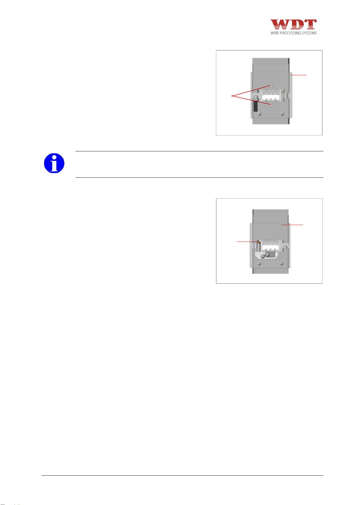
2 3 1
1
Abb. 7.4
Abb. 7.5
1. Demontage Schutzabdeckung 1.
2. Adapter Ober- und Unterteil auseinander
ziehen.
3. Gesenkpaar auswählen.
4. Gesenkschrauben 2 entfernen.
5. Untere und obere Gesenkhälfte dem
Gesenkadapter zuordnen und mit
Gesenkschrauben festziehen.
HINWEIS
+ Richtige Position der einzelnen Gesenkhälften kontrollieren. Die Größe der Profile muss
zueinander passen!
6. Gegebenenfalls Positionierer auf
Positioniereraufnahme 3 aufstecken.
7. Adapter Ober- und Unterteil wieder
zusammenschieben.
8. Schutzabdeckung 1 montieren.
UP35-4481N26000-02/15 – REV.B1 Page 21 / 63
Page 22
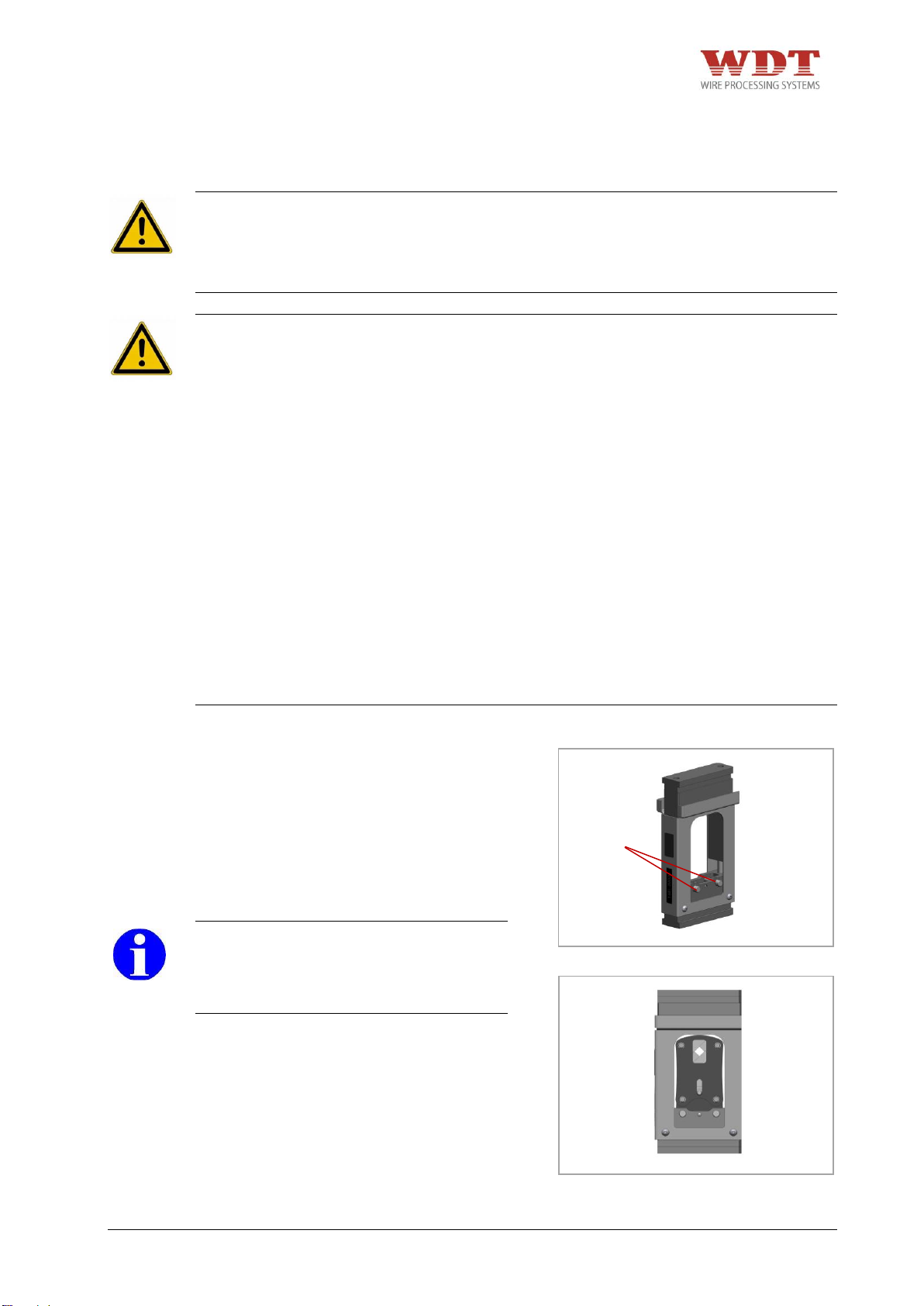
1
Abb. 7.6
Abb. 7.7
7.4 Montage der jeweiligen CSV 10-Werkzeugköpfe in den dafür
vorgesehenen Adapter
GEFAHR
+ Es besteht die Restgefahr des Quetschens von Fingern. Versuchen Sie nie, in die
Gefahrenstelle zu greifen, ohne dass die Maschine sicher von der pneumatischen
Versorgung getrennt wurde. Unterbrechen Sie die pneumatische Versorgung, bevor Sie
die Schutzabdeckung, den Gesenkadapter und das Gesenkpaar auswechseln.
WARNUNG
+ Die Crimpmaschine darf nur bei montierten Gesenkadapter, Gesenkpaar und der
dazugehörigen Schutzeinrichtung betrieben werden. Zuordnung von Gesenkadapter und
Schutzabdeckung beachten!
+ Die Crimpmaschine darf nur in einem vollständigen und funktionsfähigen Zustand
betrieben werden.
+ Vor jeder Inbetriebnahme ist zu prüfen, ob alle Sicherheitsvorrichtungen, insbesondere
Schutzabdeckungen und Gesenkadapter, angebracht sind und einwandfrei funktionieren.
+ Tragen Sie beim Arbeiten mit der pneumatischen Parallel Crimpmaschine
UP 35 keine lose Kleidung, losen Schmuck oder lange, offene Haare, welche sich in den
Teilen der pneumatischen Parallel Crimpmaschine UP 35 verfangen können.
+ Arbeiten Sie sorgfältig.
+ Es darf nur eine Person an oder mit der Maschine tätig sein.
+ Es darf nur geschultes Personal an oder mit der Maschine tätig sein.
+ Der Zugang zu den Stellteilen der Maschine muss frei gehalten werden. Es gilt
insbesondere für das Fußpedal und den Rückstell-Taster. Betätigen Sie bei drohender
Gefahr den Rückstell-Taster sofort. Der Rückstell-Taster muss vom Bediener jederzeit
direkt zugänglich bleiben. Er darf nicht verdeckt werden!
+ Es darf nur mit dem angegebenen Betriebsdruck gearbeitet werden.
1. Adapter Ober- und Unterteil so weit wie
möglich auseinander ziehen.
2. Werkzeugkopf auswählen.
3. Raststifte 1 bis Anschlag rausziehen.
4. Werkzeugkopf in Adapterunterteil
einsetzen und Raststifte 1 wieder
hineindrücken.
HINWEIS
+ Richtige Position der einzelnen Gesenk-
hälften kontrollieren. Die Größe der
Profile muss zueinander passen.
5. Adapter Ober- und Unterteil
zusammenschieben.
UP35-4481N26000-02/15 – REV.B1 Page 22 / 63
Page 23
2
1
Abb. 7.8
7.5 Montage der Adapter in Maschine
GEFAHR
+ Es besteht die Restgefahr des Quetschens von Fingern. Versuchen Sie nie, in die
Gefahrenstelle zu greifen, ohne dass die Maschine sicher von der pneumatischen
Versorgung getrennt wurde. Unterbrechen Sie die pneumatische Versorgung, bevor Sie
die Schutzabdeckung, den Gesenkadapter und das Gesenkpaar auswechseln.
WARNUNG
+ Die Crimpmaschine darf nur bei montierten Gesenkadapter, Gesenkpaar und der
dazugehörigen Schutzeinrichtung betrieben werden. Zuordnung von Gesenkadapter und
Schutzabdeckung beachten!
+ Die Crimpmaschine darf nur in einem vollständigen und funktionsfähigen Zustand
betrieben werden.
+ Vor jeder Inbetriebnahme ist zu prüfen, ob alle Sicherheitsvorrichtungen, insbesondere
Schutzabdeckungen und Gesenkadapter, angebracht sind und einwandfrei funktionieren.
+ Tragen Sie beim Arbeiten mit der pneumatischen Parallel Crimpmaschine UP 35 keine
lose Kleidung, losen Schmuck oder lange, offene Haare, welche sich in den Teilen der
pneumatischen Parallel Crimpmaschine UP 35 verfangen können.
+ Arbeiten Sie sorgfältig.
+ Es darf nur eine Person an oder mit der Maschine tätig sein.
+ Es darf nur geschultes Personal an oder mit der Maschine tätig sein.
+ Der Zugang zu den Stellteilen der Maschine muss frei gehalten werden. Es gilt
insbesondere für das Fußpedal und den Rückstell-Taster. Betätigen Sie bei drohender
Gefahr den Rückstell-Taster sofort. Der Rückstell-Taster muss vom Bediener jederzeit
direkt zugänglich bleiben. Er darf nicht verdeckt werden!
+ Es darf nur mit dem angegebenen Betriebsdruck gearbeitet werden.
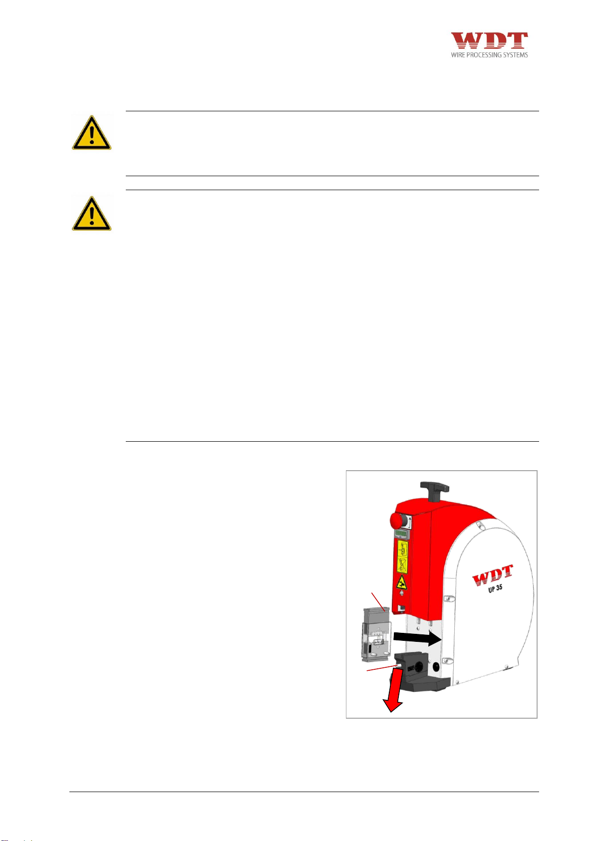
1. Pneumatischen Anschluss trennen.
2. Entriegelung 1 nach unten drücken und
halten.
3. Gesenkadapter 2 mit montierter Schutzabdeckung in die Adapteraufnahme der
Maschine einführen. Dieser Vorgang
muss leichtgängig (ohne Kraft)
ausgeführt werden, da sonst die Gefahr
der Verkantung besteht.
4. Entriegelung 1 loslassen.
5. Gesenkadapter 2 gegebenenfalls etwas
hin und her bewegen, damit die
Entriegelung 1 einrasten kann.
UP35-4481N26000-02/15 – REV.B1 Page 23 / 63
Page 24
8 Normalbetrieb /Produktionsbetrieb
GEFAHR
+ Es besteht die Restgefahr des Quetschens von Fingern. Versuchen Sie nie, in die
Gefahrenstelle zu greifen, ohne dass die Maschine sicher von der pneumatischen
Versorgung getrennt wurde. Unterbrechen Sie die pneumatische Versorgung, bevor Sie
die Schutzabdeckung, den Gesenkadapter und das Gesenkpaar auswechseln.
WARNUNG
+ Die pneumatische Parallel Crimpmaschine UP 35 darf nur in technisch einwandfreiem
Zustand sowie sicherheits- und gefahrenbewusst eingerichtet und betrieben werden.
+ Die Crimpmaschine darf nur bei montierten Gesenkadapter, Gesenkpaar und der
dazugehörigen Schutzeinrichtung betrieben werden. Zuordnung von Gesenkadapter und
Schutzabdeckung beachten!
+ Vor jeder Inbetriebnahme ist zu prüfen, ob alle Sicherheitsvorrichtungen, insbesondere
Schutzabdeckungen und Gesenkadapter, angebracht sind und einwandfrei funktionieren.
+ Tragen Sie beim Arbeiten mit der pneumatischen Parallel Crimpmaschine UP 35 keine
lose Kleidung, losen Schmuck oder lange, offene Haare, welche sich in den Teilen der
pneumatischen Parallel Crimpmaschine UP 35 verfangen können.
+ Arbeiten Sie sorgfältig.
+ Bei Feststellung von Mängeln an der Maschine muss die Arbeit unterbrochen und die
Störung behoben werden, bevor weiter mit der Maschine gearbeitet wird.
+ Es darf nur eine Person an oder mit der Maschine tätig sein.
+ Es darf nur geschultes Personal an der Maschine tätig werden.
+ Der Zugang zu den Stellteilen der Maschine muss frei gehalten werden. Es gilt
insbesondere für das Fußpedal und den Rückstell-Taster. Betätigen Sie bei drohender
Gefahr den Rückstell-Taster sofort. Der Rückstell-Taster muss vom Bediener jederzeit
direkt zugänglich bleiben. Er darf nicht verdeckt werden!
+ Es darf nur mit dem angegebenen Betriebsdruck gearbeitet werden.
VORSICHT
+ Stellen Sie die Crimpmaschine auf einer ebenen Fläche auf und sorgen Sie für
Standfestigkeit der Crimpmaschine. Stellen Sie sicher, dass die Fläche stark genug ist,
um das Gewicht der Maschine bei normaler Benutzung aufnehmen zu können. Während
des Betriebs muss die Maschine auf einem Tisch oder einer ähnlichen Ebene stehen.
+ Das Fußpedal muss auf den Boden gestellt werden. Jede andere Platzierung des
Fußpedals als auf dem Fußboden ist untersagt. Das Fußpedal muss verschoben werden
können, damit der Bediener seine Position wechseln kann und weniger schnell ermüdet.
Fußpedal nicht in Verkehrswegen verlegen.
+ Verlegen Sie die Schläuche am Boden so, dass sie keine Stolpergefahr bilden.
Crimpvorgang ohne Positionierer
1. Legen Sie den Crimpkontakt in das Gesenk ein; dabei die korrekte Zuordnung zu dem
jeweiligen Crimpprofil und den ordnungsgemäßen Sitz in dem Crimpprofil achten!
2. Legen Sie nach Spezifikation abisolierten Leiter in den Kontakt ein und positionieren Sie
diesen.
3. Betätigen Sie das Fußpedal.
4. Halten Sie das Fußpedal gedrückt, bis der Crimpvorgang beendet ist.
5. Entnehmen Sie den gecrimpten Kontakt.
UP35-4481N26000-02/15 – REV.B1 Page 24 / 63
Page 25
Crimpvorgang mit Positionierer:
1. Klappen Sie den Positionierer auf.
2. Legen Sie den Crimpkontakt in den Positionierer ein; Dabei die korrekte Zuordnung zu
dem jeweiligen Crimpprofil und den ordnungsgemäßen Sitz in dem Crimpprofil achten!
3. Schließen und verriegeln Sie den Positionierer.
4. Legen Sie den nach Spezifikation abisolierten Leiter in den Kontakt ein und positionieren
Sie diesen.
5. Betätigen Sie das Fußpedal.
6. Halten Sie das Fußpedal gedrückt, bis der Crimpvorgang beendet ist.
7. Öffnen Sie den Positionierer und entnehmen Sie den gecrimpten Kontakt.
9 Instandhaltung
GEFAHR
+ Es besteht die Restgefahr des Quetschens von Fingern. Versuchen Sie nie, in die
Gefahrenstelle zu greifen, ohne dass die Maschine sicher von der pneumatischen
Versorgung getrennt wurde. Unterbrechen Sie die pneumatische Versorgung, bevor Sie
die Schutzabdeckung, den Gesenkadapter und das Gesenkpaar auswechseln.
WARNUNG
+ Der Druckluftanschluss darf eine Schlauchlänge von 1 Meter nicht überschreiten und
muss über einen Kupplungsanschluss verfügen.
+ Vor Beginn von Wartungs-, Demontage- und Instandhaltungsarbeiten muss die
pneumatische Parallel Crimpmaschine UP 35 sicher von der pneumatischen Versorgung
getrennt sein.
+ Instandhaltungsarbeiten dürfen nur von berechtigten und für diese Tätigkeit
ausgebildeten Personen ausgeführt werden. Insbesondere Gehäuse und Abdeckungen
dürfen nur von fachkundigem Personal entfernt werden.
+ Tragen Sie beim Arbeiten mit der pneumatischen Parallel Crimpmaschine UP 35 keine
lose Kleidung, losen Schmuck oder lange, offene Haare, welche sich in den Teilen der
pneumatischen Parallel Crimpmaschine UP 35 verfangen können.
+ Die Crimpmaschine darf nur in einem vollständigen und funktionsfähigen Zustand
betrieben werden.
+ Die Crimpmaschine darf nur bei montierten Gesenkadapter, Gesenkpaar und der
dazugehörigen Schutzeinrichtung betrieben werden. Zuordnung von Gesenkadapter und
Schutzabdeckung beachten!
+ Arbeiten Sie sorgfältig.
+ Es darf nur eine Person an oder mit der Maschine tätig sein.
+ Der Zugang zu den Stellteilen der Maschine muss frei gehalten werden. Es gilt
insbesondere für das Fußpedal und den Rückstell-Taster. Betätigen Sie bei drohender
Gefahr den Rückstell-Taster sofort. Der Rückstell-Taster muss vom Bediener jederzeit
direkt zugänglich bleiben. Er darf nicht verdeckt werden!
+ Es darf nur mit dem angegebenen Betriebsdruck gearbeitet werden.
UP35-4481N26000-02/15 – REV.B1 Page 25 / 63
Page 26
9.1 Wartungsplan
GEFAHR
+ Es besteht die Restgefahr des Quetschens von Fingern. Versuchen Sie nie, in die
Gefahrenstelle zu greifen, ohne dass die Maschine sicher von der pneumatischen
Versorgung getrennt wurde. Unterbrechen Sie die pneumatische Versorgung, bevor Sie
die Schutzabdeckung, den Gesenkadapter und das Gesenkpaar auswechseln.
WARNUNG
+ Vor Beginn von Wartungs-, Demontage- und Instandhaltungsarbeiten muss die
pneumatische Parallel Crimpmaschine UP 35 sicher von der pneumatischen Versorgung
getrennt sein.
+ Instandhaltungsarbeiten dürfen nur von berechtigten und für diese Tätigkeit
ausgebildeten Personen ausgeführt werden. Insbesondere Gehäuse und Abdeckungen
dürfen nur von fachkundigem Personal entfernt werden.
+ Tragen Sie beim Arbeiten mit der pneumatischen Parallel Crimpmaschine UP 35 keine
lose Kleidung, losen Schmuck oder lange, offene Haare, welche sich in den Teilen der
pneumatischen Parallel Crimpmaschine UP 35 verfangen können.
+ Arbeiten Sie sorgfältig.
+ Geeignete Schutzhandschuhe und Schutzbrille bei Schmierungsarbeiten tragen.
Beachten Sie die Sicherheitshinweise im "Sicherheitsdatenblatt" des Schmierfettes bzw.
Öls.
Regelmäßige Reinigung und Wartung der von außen zugänglichen Teile erhält die
Betriebsbereitschaft der Maschine. Zur Reinigung der Maschine keine fasernden Materialien
wie Putzwolle o. ä. verwenden. Die Maschine oder Maschinenteile dürfen nicht mit Druckluft
gereinigt werden. Die Crimpmaschine oder Maschinenteile dürfen nicht mit harten
Gegenständen wie Spachtel, Stahlwolle o. ä. gereinigt werden. Grobe Verschmutzung und
Abrieb absaugen.
9.1.1 Täglich
+ Optische Kontrolle der pneumatischen Parallel Crimpmaschine UP 35.
+ Kontrolle Druckluft (max. 6 bar) an Hausanlage kontrollieren (Manometer nicht im
Lieferumfang enthalten).
+ Ölstand Wartungseinheit an Hausanlage überprüfen (nicht im Lieferumfang enthalten).
UP35-4481N26000-02/15 – REV.B1 Page 26 / 63
Page 27
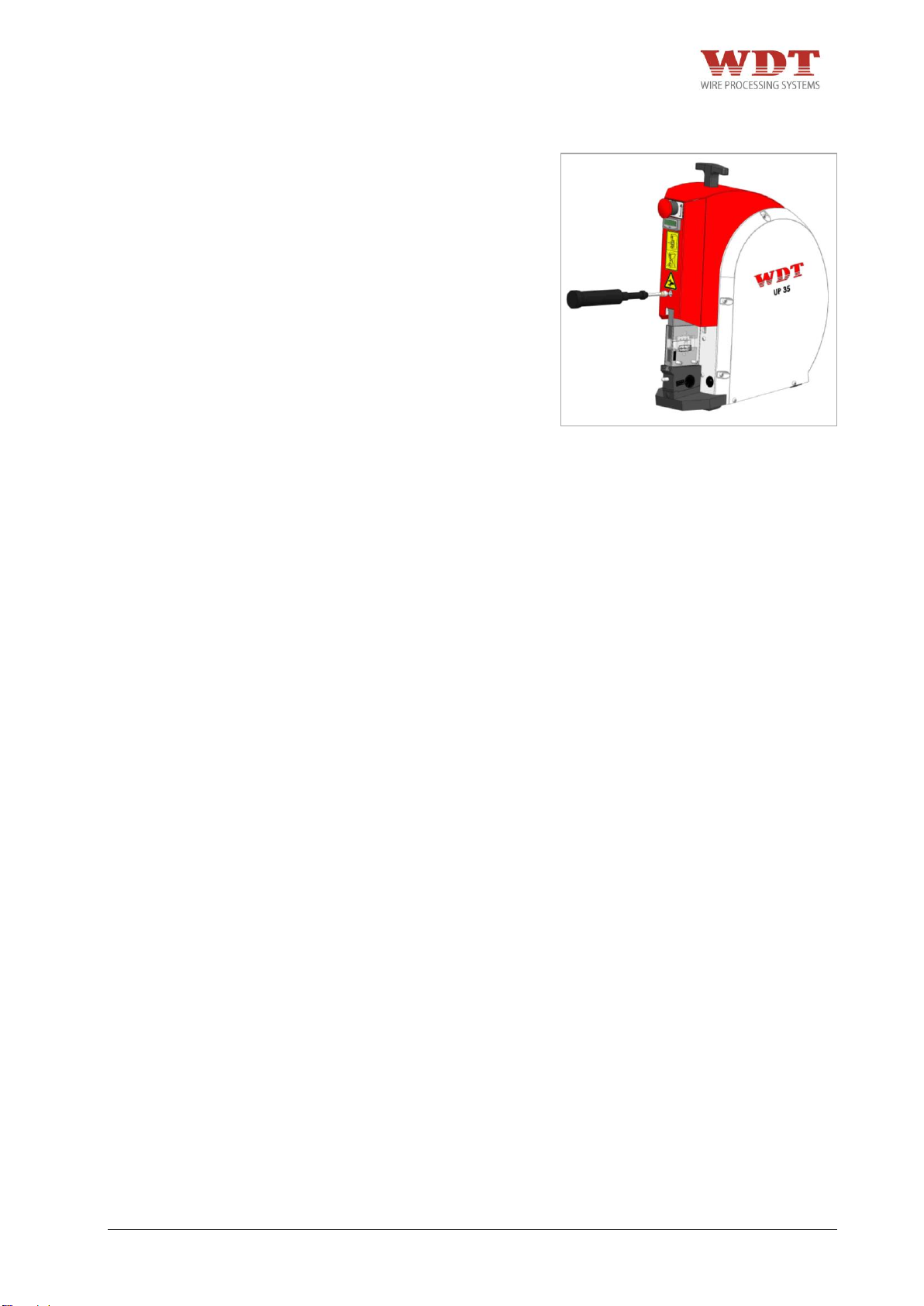
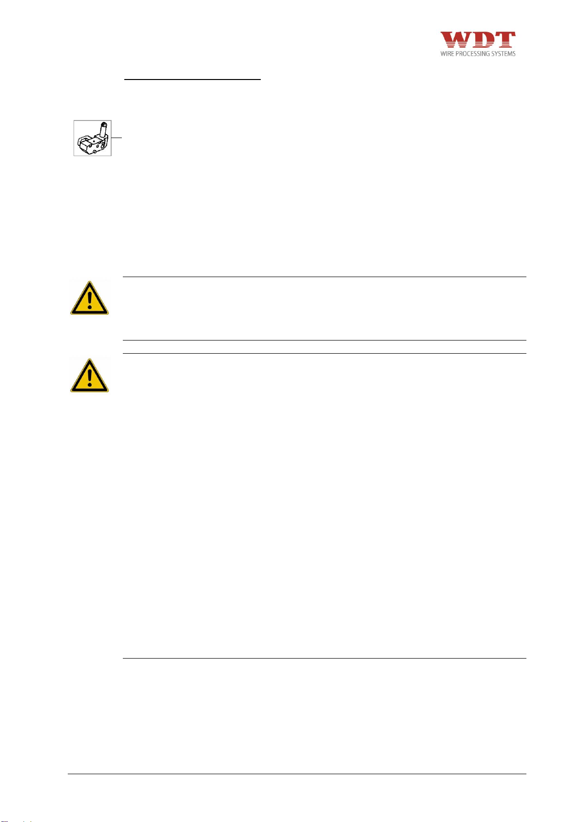
Abb. 9.1
9.1.2 Monatlich
Schmieren des Crimpstößels durch
Schmiernippel und mitgelieferte Stoßdruckpresse mit einem der folgenden Fette:
+ Blaser Swiss Lube Art.-Nr. 00492-01 EP-
Universal Fett.
+ Molykote DX Paste
+ Dininol Fett LGM2, Art.-Nr. 27620
(Zellner+Gmelin GmbH & Co. KG)
Alternativ können Litiumseifenschmierfette
mit folgenden Anwendungsgebieten
verwendet werden:
+ Gleitflächen/Reibkontakte
+ hohe Lasten
+ nicht schmutzende Schmierung
+ geringe und mittlere Drehzahlen
+ Grundölviskosität bei 40°C (DIN 51562): 110mm²/s
9.1.3 Nach jeweils 25.000 Zyklen oder alle zwei Jahre
Für Inspektionen in den empfohlenen Abständen, kontaktieren Sie bitte den Hersteller bzw.
Händler.
Service-Adresse:
WEZAG GmbH
Werkzeugfabrik
Wittigstraße 8
35260 Stadtallendorf
Telefon: +49 6428 704-0
UP35-4481N26000-02/15 – REV.B1 Page 27 / 63
Page 28
10 Fehlersuche und Störungsanalyse
GEFAHR
+ Es besteht die Restgefahr des Quetschens von Fingern. Versuchen Sie nie, in die
Gefahrenstelle zu greifen, ohne dass die Maschine sicher von der pneumatischen
Versorgung getrennt wurde. Unterbrechen Sie die pneumatische Versorgung, bevor Sie
die Schutzabdeckung, den Gesenkadapter und das Gesenkpaar auswechseln.
WARNUNG
+ Vor Beginn von Wartungs-, Demontage- und Instandhaltungsarbeiten muss die
Crimpmaschine sicher von der pneumatischen Versorgung getrennt sein.
+ Instandhaltungsarbeiten dürfen nur von berechtigten und für diese Tätigkeit
ausgebildeten Personen ausgeführt werden. Insbesondere Gehäuse und Abdeckungen
dürfen nur von fachkundigem Personal entfernt werden.
+ Tragen Sie beim Arbeiten mit der pneumatischen Parallel Crimpmaschine UP 35 keine
lose Kleidung, losen Schmuck oder lange, offene Haare, welche sich in den Teilen der
pneumatischen Parallel Crimpmaschine UP 35 verfangen können.
+ Arbeiten Sie sorgfältig.
+ Vor jeder Inbetriebnahme ist zu prüfen, ob alle Sicherheitsvorrichtungen, insbesondere
Schutzabdeckungen und Gesenkadapter, angebracht sind und einwandfrei funktionieren.
+ Prüfen Sie die Funktionsfähigkeit des Rückstell-Tasters vor Beginn Ihrer Arbeit an der
Crimpmaschine. Betätigen Sie bei drohender Gefahr den Rückstell-Taster sofort. Der
Rückstell-Taster muss vom Bediener jederzeit direkt zugänglich bleiben. Er darf nicht
verdeckt werden!
HINWEIS
+ Bei einer Blockade des Gesenkpaars betätigen Sie den Rückstell-Taster und trennen Sie
die Maschine vom Druckluftnetz.
Bei Problemen steht Ihnen der WEZAG Gmb Kundendienst zu Verfügung.
Service-Adresse:
WEZAG GmbH
Werkzeugfabrik
Wittigstraße 8
35260 Stadtallendorf
Telefon: +49 6428 704-0
Halten Sie für das Gespräch bitte alle notwendigen Informationen bereit, u. a.
+ Maschinentyp
+ Seriennummer der Maschine
UP35-4481N26000-02/15 – REV.B1 Page 28 / 63
Page 29
11 Außerbetriebnahme, Abbau, Demontage
GEFAHR
+ Es besteht die Restgefahr des Quetschens von Fingern. Versuchen Sie nie, in die
Gefahrenstelle zu greifen, ohne dass die Maschine sicher von der pneumatischen
Versorgung getrennt wurde. Unterbrechen Sie die pneumatische Versorgung, bevor Sie
die Schutzabdeckung, den Gesenkadapter und das Gesenkpaar auswechseln.
WARNUNG
+ Vor Beginn von Wartungs-, Demontage- und Instandhaltungsarbeiten muss die
pneumatische Parallel Crimpmaschine UP 35 sicher von der pneumatischen Versorgung
getrennt sein.
+ Instandhaltungsarbeiten dürfen nur von berechtigten und für diese Tätigkeit
ausgebildeten Personen ausgeführt werden. Insbesondere Gehäuse und Abdeckungen
dürfen nur von fachkundigem Personal entfernt werden.
+ Tragen Sie beim Arbeiten mit der pneumatischen Parallel Crimpmaschine UP 35 keine
lose Kleidung, losen Schmuck oder lange, offene Haare, welche sich in den Teilen der
pneumatischen Parallel Crimpmaschine UP 35 verfangen können.
+ Es darf nur eine Person an oder mit der Maschine arbeiten.
+ Arbeiten Sie sorgfältig.
12 Lagerung
Maschine bei Raumtemperatur in der Originalkiste lagern.
13 Entsorgung
Zur Entsorgung der pneumatischen Parallel Crimpmaschine UP 35, ist diese an WEZAG
GmbH zurück zu liefern.
UP35-4481N26000-02/15 – REV.B1 Page 29 / 63
Page 30
Pos.-Nr.
Stück
Artikel-Nr.
Benennung
1
1
2481-02001
Grundplatte
2
5
8480-89003
Sockel selbstklebend 31,7x31,7x6,1
3
2
2481-25006
Seitenwand
4
4
8481-02013
Zylinderbuchse Ø16/12x10
5
8
8480-99069
Senkschraube mit Iskt. M6x35 DIN7991
6
1
1481-26003
Zylindereinheit
7
4
8480-10111
Zylinderschraube mit Iskt. M6x25 DIN912
8
2
2481-02023
Bolzen Ø6h9 x 60
9
4
8481-02007
Sicherungsring DIN 471-6x0,7
10
3
2480-89024
Gelenkwelle-1296-18
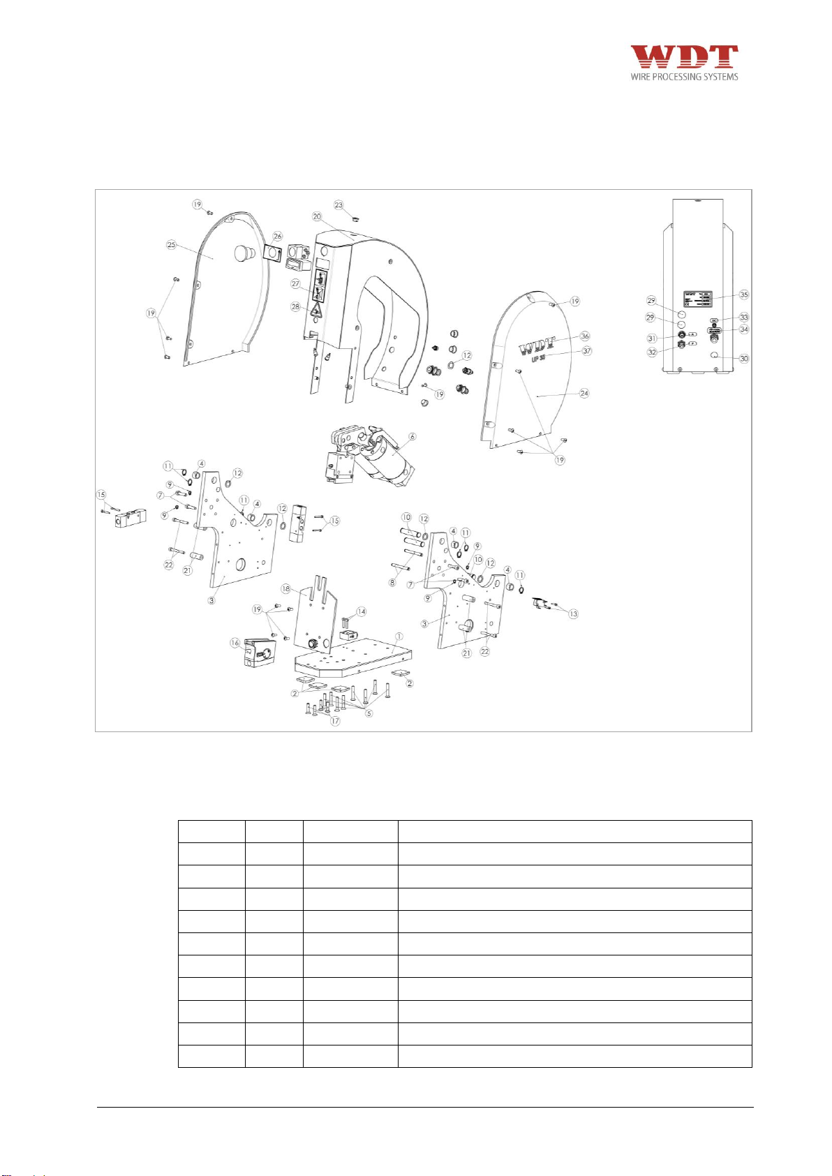
Abb. 14.1
14 Ersatzteilliste, Pneumatikschema
14.1 Explosionszeichnung
14.2 Stückliste Explosionszeichnung
UP35-4481N26000-02/15 – REV.B1 Page 30 / 63
Page 31

Pos.-Nr.
Stück
Artikel-Nr.
Benennung
11
6
8480-99161
Sicherungsring DIN 471-12x1
12
5
8481-25007
Pass-Scheibe Ø12/18 x0,5 DIN988
13
2
8480-99121
Zylinderschraube mit Iskt. M3x14 DIN912
14
2
8180-23002
Zylinderschraube mit Iskt. M4x20 DIN912
15
4
8480-89010
Zylinderschraube mit Iskt. M3x25 DIN912
16
1
1481-25002
Verstelleinheit
17
4
8481-02004
Senkschraube mit Iskt. M6x25 DIN7991
18
1
2481-25005
Abdeckblech
19
16
8481-02008
Linsenschraube mit Iskt. M5x12 (verzinkt-blau)
20
1
1481-25001
Haube komplett
21
4
2481-02020
Distanzbuchse 12,00/5,3x33,5
22
4
8480-99127
Zylinderschraube mit Iskt. M5x45 DIN912
23
1
8481-02001
Verschlussschraube EVSG M12 - RAL 9005
24
1
2481-02017
Abdeckung rechts
25
1
2481-02018
Abdeckung links
26
1
5481-02002
Aufkleber "Release"
27
1
5480-88002
Aufkleber "Hinweis Fingerschutz"
28
1
5480-81005
Klebeetikett, Warnung vor Handverletzungen
29
2
8481-06001
Zierstopfen Ø14,9/18,5 schwarz
30
1
8201-00002
Abdeckstopfen
31
1
5481-03003
Aufkleber A
32
1
5481-02006
Aufkleber P
33
1
5481-03002
Aufkleber DC
34
1
5481-02007
Aufkleber Air-max.
35
1
4481-26100
Typenschild
36
2
5480-81027
Aufkleber "WDT" rot
37
2
5481-06001
Aufkleber "UP35" schwarz
38
1
1481-26002
Pneumatik komplett
39
1
1481-25009
Elektrik komplett
Die Reparatur der Maschine muss durch speziell geschultes Personal erfolgen. Bitte wenden
Sie sich an den Hersteller bzw. Händler der Maschine!
Service-Adresse:
WEZAG GmbH
Werkzeugfabrik
Wittigstraße 8
35260 Stadtallendorf
Telefon: +49 6428 704-0
UP35-4481N26000-02/15 – REV.B1 Page 31 / 63
Page 32
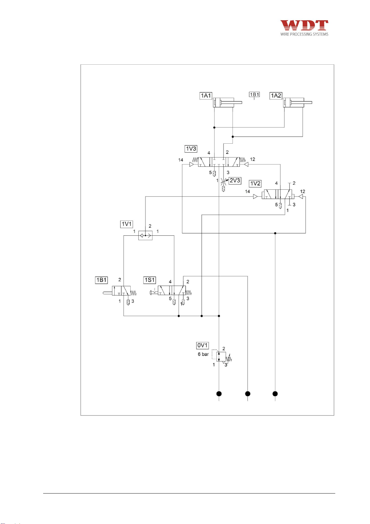
Abb. 14.2
14.3 Pneumatik Schema
UP35-4481N26000-02/15 – REV.B1 Page 32 / 63
Page 33
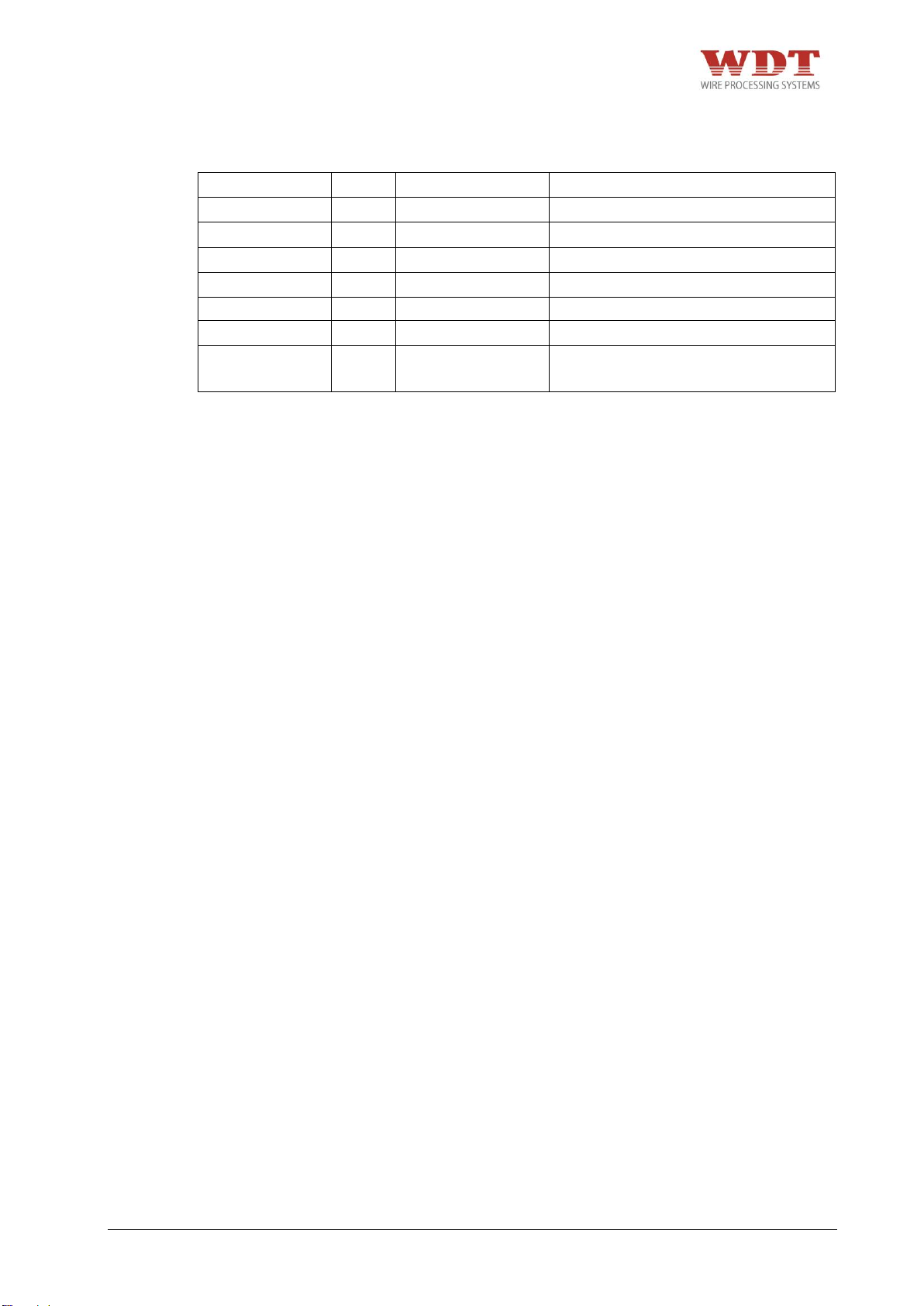
Kennzeichnung
Stück
Artikelnummer
Beschreibung
1V1
1
8480-88086
Wechselventil
1V2
1
8480-85002
5/2 Wegeventil
1V3
1
8480-88089
5/3 Wegeventil
1B1
1
8480-88005
Taster (1A1 ausgefahren)
0V1
1
8481-03003
Druckregelventil, einstellbar
2V3
1
8480-88073
Drosselventil
1S1
1
8481-03042 +
8481-03018
Pilztaster rot inkl. Ventil
14.4 Stückliste Pneumatik Schema
Die Reparatur der Maschine muss durch speziell geschultes Personal erfolgen. Bitte wenden
Sie sich an den Hersteller bzw. Händler der Maschine!
Service-Adresse:
WEZAG GmbH
Werkzeugfabrik
Wittigstraße 8
35260 Stadtallendorf
Telefon: +49 6428 704-0
14.5 Zubehörübersicht für Nachbestellungen
1. Pneumatisches Fußpedal mit Schutzhaube Bestellnr.: 1481-03033
2. Anschlussschlauch-Set Bestellnr.: 1881-03001
3. Werkzeugschlüssel-Set Bestellnr.: 1881-02002
4. Fett-Stoßdruckpresse Bestellnr.: 9480-88019
5. T-Griff Bestellnr.: 8481-02005
6. Steckernetzteil mit Wechseladapter Bestellnr.: 1881-03005
UP35-4481N26000-02/15 – REV.B1 Page 33 / 63
Page 34

Table of Contents
1 Introduction ....................................................................................................................................... 35
1.1 Product Sprecification .................................................................................................................. 35
1.2 Conformity .................................................................................................................................... 36
1.3 Dealing with the Operating Instruction ......................................................................................... 37
2 Safety ................................................................................................................................................. 37
2.1 Warning & Safety Precautions in this Operating Instruction ........................................................ 37
2.2 Safety Precautions ....................................................................................................................... 38
2.3 Responsibilities ............................................................................................................................ 39
2.4 Desinged Use ............................................................................................................................... 40
2.5 Predictable Misuse ....................................................................................................................... 40
2.6 Hazardous Areas ......................................................................................................................... 40
3 Shipment ............................................................................................................................................ 41
3.1 Packing ........................................................................................................................................ 41
3.2 Packing Contents ......................................................................................................................... 41
4 Technical Description ...................................................................................................................... 42
4.1 Operators Guide ........................................................................................................................... 42
4.2 Machine Identification .................................................................................................................. 43
4.3 Technical Data ............................................................................................................................. 43
4.4 Safety Guard ................................................................................................................................ 43
4.5 Release Button ............................................................................................................................. 43
5 Transport and Installation ................................................................................................................ 44
5.1 Transport ...................................................................................................................................... 44
5.2 Installation .................................................................................................................................... 44
6 Commissioning ................................................................................................................................. 45
6.1 Connecting to Compressed Air Supply ........................................................................................ 45
6.2 Control of the crimp Height .......................................................................................................... 47
7 Tooling ............................................................................................................................................... 48
7.1 Available Adapters ....................................................................................................................... 48
7.2 Adapter Assembly ........................................................................................................................ 49
7.3 Mounting of respecitve die set into the designed adapter ........................................................... 50
7.4 Mounting of respecitve tool head into the designed adapter ....................................................... 52
7.5 Mounting adapter into the machine .............................................................................................. 53
8 Normal Operation / Production Cycle ............................................................................................. 54
9 Maintenance ...................................................................................................................................... 55
9.1 Maintenance Plan ........................................................................................................................ 56
9.1.1 Daily ...................................................................................................................................... 56
9.1.2 Monthly ................................................................................................................................. 57
9.1.3 After every 25.000 crimp cycles or every 2 years ................................................................. 57
10 Problem Handling and Fault Diagnostics ...................................................................................... 58
11 Removal from Service, Demounting, Disassembly, ...................................................................... 59
12 Storage ............................................................................................................................................... 59
13 Disposal ............................................................................................................................................. 59
14 Exploded View Drawing, Spare Part List, Pneumatic Diagram .................................................... 60
14.1 Exploded View Drawing ............................................................................................................... 60
14.2 Parts List Exploded View Drawing ............................................................................................... 60
14.3 Pneumatic Diagram...................................................................................................................... 62
14.4 Parts List Pneumatic .................................................................................................................... 63
14.5 Accessories overview for re orders .............................................................................................. 63
UP35-4481N26000-02/15 – REV.B1 Page 34 / 63
Page 35

1 Introduction
1.1 Product Sprecification
The pneumatic Parallel Crimp Machine UP 35 is a bench top pneumatic crimp machine that
is compatible with the WEZAG interchangeable crimping system. With the pneumatic
Parallel Crimp Machine UP 35 the most common terminals on the market can be crimped
with the WEZAG interchangeable crimping systems.
According to the type of terminal an interchangeable suitable crimping die is selected and
installed into the die holders (inclusive safety guard).
Utilizing the enclosed pneumatic foot pedal, the crimping cycle of the pneumatic Parallel
Crimp Machine UP 35 is activated and allows the operator to have both hands free to insert
the terminal and wire. All pneumatic Parallel Crimp Machines UP 35 are equipped with a
positive closing mechanism and ensure consistent crimp quality.
The pneumatic Parallel Crimping Machine UP 35 has an emergency release button, that will
open the crimping jaws in the event of blocked jaws caused by operation or handling errors
or wrongly placed terminals.
All other applications of the pneumatic Parallel Crimp Machine UP 35 are only permitted with
a written permission of the manufacturer. For all unauthorized applications of the pneumatic
Parallel Crimp Machine UP 35 the manufacturer cannot be held liable for any resultant
damage or injury.
UP35-4481N26000-02/15 – REV.B1 Page 35 / 63
Page 36
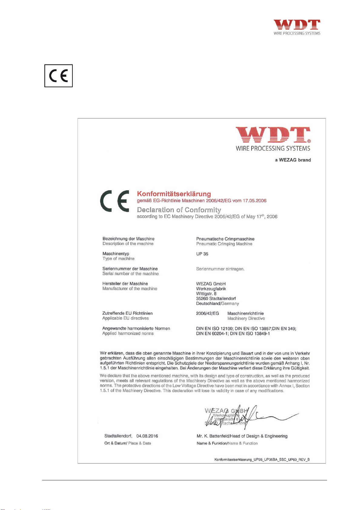
Fig. 1.1
1.2 Conformity
The machine may only be used for the purpose specified in the operating instruction. The
producer as well as the distributor will not be liable for any damages which may result due to
the machine being used for a purpose other than that for which it was intended. This is
done entirely at the user’s own risk.
The pneumatic Parallel Crimp Machine UP 35 is CE compliant. The original of the
following declaration of conformity was supplied together with the operating
instructions of the machine:
1.3
UP35-4481N26000-02/15 – REV.B1 Page 36 / 63
Page 37
Dealing with the Operating Instruction
The operating instruction manual contains all information concerning operating elements,
operation, commissioning and maintenance work as well as technical data.
The operation manual must be constantly within reach of the pneumatic Parallel Crimp
Machine UP 35. Every machine operator must read and understand the operating instruction
in order to have safe and efficient production with this piece of equipment.
The producer as well as the distributor decline to accept any liability for damages that are
incurred due to the fact that the instructions on the machine or in the operation instruction
have been disregarded.
The user is responsible for supplementing the operation instruction with any instructions
resulting from current national regulations for accident prevention and protection of the
environment.
The German original version is legally binding.
This operating instruction has to be guarded for later use.
2 Safety
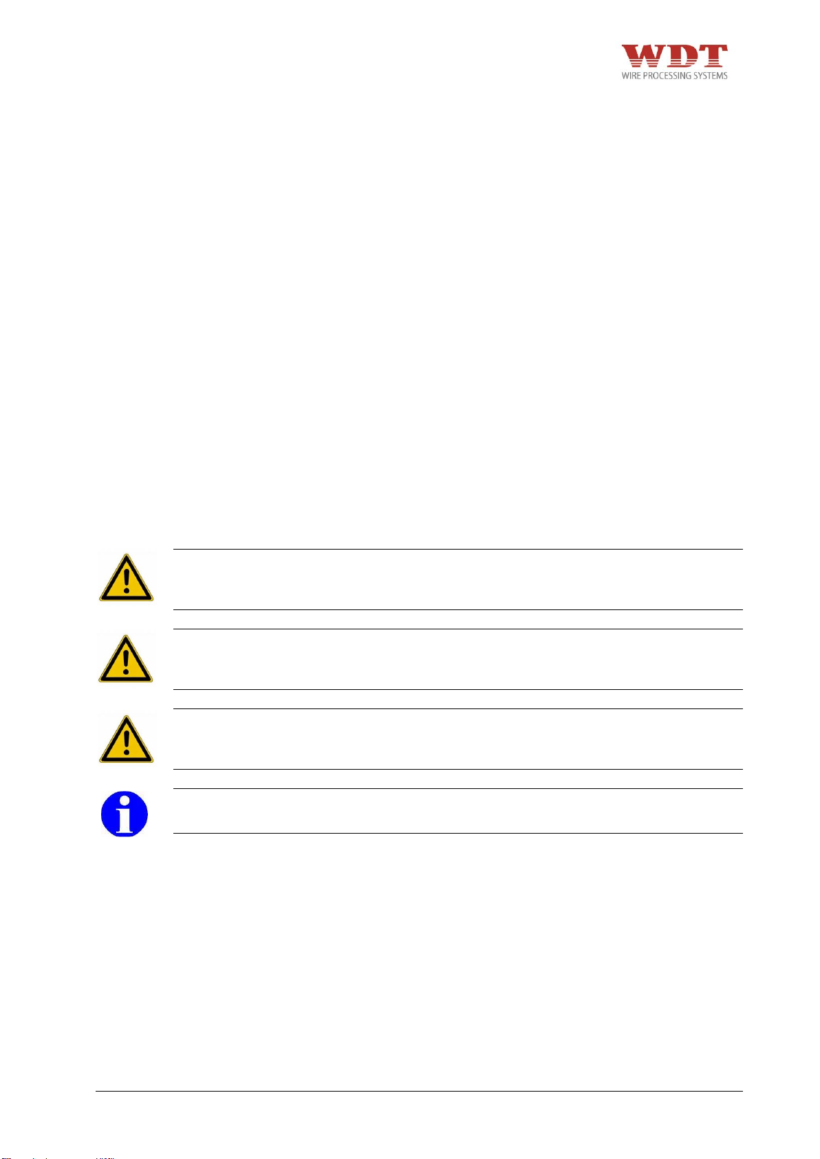
2.1 Warning & Safety Precautions in this Operating Instruction
The following warnings and safety related cautionary notices in the individual chapters alert
you to various levels of danger:
DANGER
+ Identifies an imminent, serious danger, which, if it is not avoided, will lead to serious
injuries or even to death.
CAUTION
+ Identifies a possible danger, which, if it is not avoided, will lead to serious injuries or
even to death.
ATTENTION
+ Identifies a potential dangerous situation, which, if it is not avoided, can lead to
medium or minor injuries or material damages.
INFORMATION
+ If this information is not followed, it can lead to a deterioration of the operating procedure.
UP35-4481N26000-02/15 – REV.B1 Page 37 / 63
Page 38

2.2 Safety Precautions
The pneumatic Parallel Crimp Machine UP 35 has been constructed according to state-ofthe-art technology and the acknowledged technical safety regulations.
When carrying out jobs such as installation, putting the machine into operation or setting it
up, operation, changing the conditions of use and the mode of operation or carrying out
maintenance and service jobs, it is important to observe the procedures for switching off the
machine described in the operation instruction.
Please observe the national regulations according to the minimum age of the personnel
operating the pneumatic Parallel Crimp Machine UP 35. Allowing younger persons access to
the machine is strictly prohibited.
+ Do not operate the pneumatic Parallel Crimp Machine UP 35 until you have studied and
fully understood all the instructions described in this operating instruction.
+ Operate the pneumatic Parallel Crimp Machine UP 35 in a dry and dust free environment
only. The crimp machine is only allowed to be used when it is in a completely functional
condition.
+ Do not modify the pneumatic Parallel Crimp Machine UP 35 nor use it for any purpose for
which it was not intended.
+ The use of a chain hoist or lifting device is recommended for the transport of the crimping
machine.
+ The pneumatic Parallel Crimp Machine UP 35 has to be carried with the T handle for the
transport by hand. Wear suitable safety shoes when transporting and installing the
machine.
+ Position the pneumatic Parallel Crimp Machines UP 35 on a flat surface and assure the
stability of the machine. Ensure that the table or bench is stable enough to support the
machine in normal use. During the utilization the machine has to be placed on a table or
a similar flat surface.
+ Assure an appropriate table height. The table height is dependent on the position of the
operator, (work in sitting or standing position) according to prEN 894-4:2004, Table A.1.
+ Assure appropriate illumination of the working place. (EN 1837:1999 – chapter 4.2: “The
general value of illumination has to be 500 lx [...]").
+ Connect compressed air supply with supplied compressed air tube (length 1 m).
+ The compressed air connection tube must not be longer than 1 m and has to have a
coupling connection.
+ Place the tubes on the floor or out of the way so that they do not cause a trip hazard.
+ Tubes must not be damaged.
+ Place the foot pedal on the floor. No other place is allowed.
+ Do not lay the foot pedal in aisles or walkways.
+ Assure free access to the operating elements of the machine, especially the foot pedal
and the release button. In the case of imminent danger immediately press the release
button. The release button must be within the direct reach of the operator. It must not be
covered.
+ Before starting maintenance, disassembly or repair work, the crimp machine must be
disconnected from air supply.
+ Maintenance work may be performed only by authorized and properly trained personal.
The housing and the covers in particular may only be removed by specially trained staff.
+ Due to the risk of hand or finger injury, never try to reach into the machine before having
assured that the machine is disconnected from the air supply. Disconnect the air supply
before changing the safety guard, the adapter and the dies.
+ Before commissioning the machine, it is always important to check whether all safety
devices, especially the safety guards and die adapter, are installed and are functioning
correctly.
UP35-4481N26000-02/15 – REV.B1 Page 38 / 63
Page 39

+ Check the release button before starting the work on the crimp machine. In the case of
imminent danger immediately press the release button. The release button must be within
the direct reach of the operator. It must not be covered.
+ Exercise caution at all times when the pneumatic Parallel Crimp Machine UP 35 is
switched on.
+ The pneumatic Parallel Crimp Machine UP 35 is only allowed to be operated with a
mounted adapter with die set and suitable safety guard. Pay attention to the correct
assignment of adapter to safety guard.
+ The pneumatic Parallel Crimp Machine UP 35 may only be set up and operated in perfect
technical condition, observing all the safety regulations and considering any possible
dangers.
+ In cases of a machine malfunction, production must be stopped and the malfunction must
be fixed before continuing work with the machine.
+ Work with caution.
+ Only one person is allowed to work on or with the machine at a time.
+ Only trained personal are allowed to work on or with the machine.
+ It is only allowed to work with the specified crimping force.
+ When working with the pneumatic Parallel Crimp Machine UP 35, do not wear loose
clothing, jewelry or long, loose hair that can get caught in the pneumatic Parallel Crimp
Machine UP 35.
+ Disconnect the pneumatic Parallel Crimp Machine UP 35 from the air supply before
attempting any maintenance work. Due to the risk of hand or finger injury, never try to
reach into the machine before having assured that the machine is disconnected from the
air supply.
+ The machine can only be depressurized by disconnecting the machine from the main air
supply Air MAX.
+ Wear protective gloves and safety glasses during lubrication work. Please pay attention
to the safety instructions in the “safety data sheet” of the grease.
+ During transport of the machine wear suitable safety shoes.
2.3 Responsibilities
The pneumatic Parallel Crimp Machine UP 35 may only be operated by suitably trained and
authorized personnel. The user must clearly define and observe the responsibilities of the
personnel for operation, set-up, maintenance and service. It is particularly important to define
who is responsible for work on the pneumatic equipment. Such work should only be carried
out by specially trained staff.
Should the user make any changes to the machine without consulting the manufacturers or
the distributors, the latter will not be liable for any damage that may result.
The user of the pneumatic Parallel Crimp Machine UP 35 is responsible for making sure that
all persons involved in any way, either in the installation or in maintenance of the machine,
have been thoroughly trained on the system using the this operating instruction.
The user is also responsible for the training of operators and the instruction must include the
following aspects:
+ Purpose of the machine
+ Hazard zones
+ Safety rules and regulations
+ Functionality of the various components of the machine
+ Proper operation of the machine
UP35-4481N26000-02/15 – REV.B1 Page 39 / 63
Page 40
Staff qualifications required in conjunction with the use of the pneumatic Parallel
Crimp Machine UP 35:
Installation
Set-up
Instruction
Technical personnel with language proficiency in either English
or German, in addition to the native language of the operator.
Operation
Through qualified personnel trained as indicated above.
Maintenance
Service
Technical personnel with proficiency in English or German.
To assure full familiarization with the system, the training must be conducted in the native
language of the operators involved.
The safety instructions, warnings and precautions contained in the individual chapters must
be strictly observed by all users and operators.
2.4 Desinged Use
+ Realization of crimp connections up to a cable Ø of 50 mm² depending on the terminal
design.
The pneumatic Parallel Crimp Machine UP 35 is designed for usage with the adapters
described in section 7. The adapter should only be used with the dies specified by WEZAG.
It is only allowed to use the pneumatic Crimp Machine UP 35 together with the adapter,
safety cover and die sets for the preparation of crimp connections!
2.5 Predictable Misuse
+ Every application which is not mentioned in chapter 2.4 „Designed Use“.
2.6 Hazardous Areas
1. Hazardous Area: Area of interchangeable crimping dies
Person at risk: Operator
Type of Hazard: Hand Injuries
2. Hazardous Area: Opened machine
Person at risk: Installation Engineer
Type of Hazard: Direct or indirect contact with movable parts of the machine,
Hand injuries (cuts from sharp edges)
Hand injuries (risk of crushing)
UP35-4481N26000-02/15 – REV.B1 Page 40 / 63
Page 41
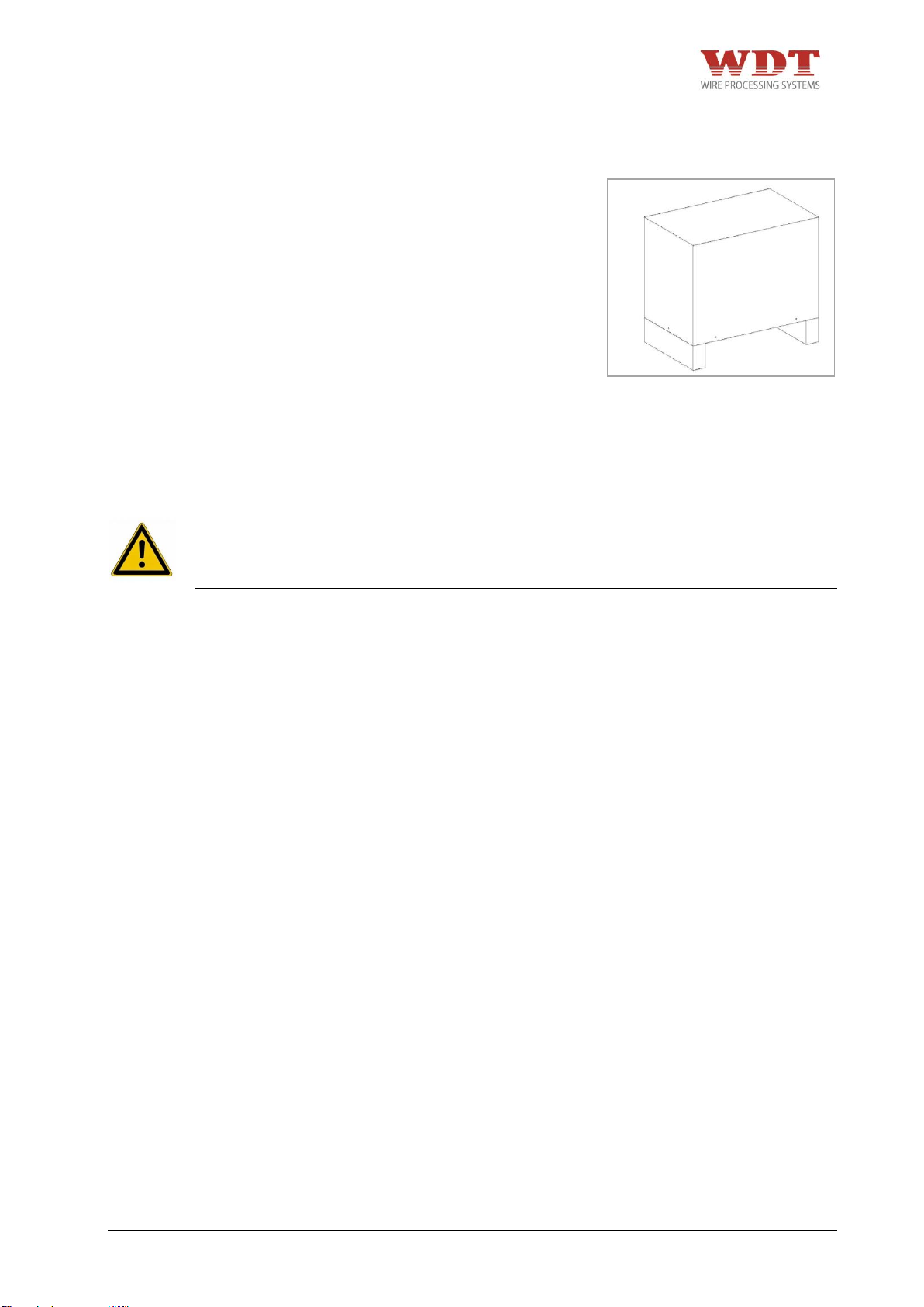
1 pc
Pneumatic Parallel Crimp Machine UP 35 with counter and operating
instruction (without adapter and die set)
1 pc
Finger protection
1 pc
Pneumatic foot pedal with cover
1 pc
Hexagon allen key 2,0 mm
1 pc
Hexagon allen key 2,5 mm
1 pc
Grease gun
1 pc
PU compressed air hose Ø 8/6 mm at 1 meter
1 pc
PU compressed air hose Ø 6/4 mm at 2 meters
1 pc
PU compressed air hose Ø 4/2 mm at 2 meters
1 pc
T-handle
1 pc
Power supply 12 V with changeable adapter for EU/US/UK/AU
1 pc
Declaration of conformity
Fig. 3.1
3 Shipment
3.1 Packing
Upon receipt, unpack the pneumatic Parallel
Crimp Machine UP 35 carefully and check
that you have received all components
against the packing slip, declaration of
conformity and operating instructions. We
recommend that you retain the packing for
further dispatch and for storage.
Dimension:
Length: 560 mm
Width: 350 mm
Height: 610 mm
Gross-Weight: approx. 35 kg
DANGER
+ The use of a chain hoist or lifting device is recommended for the transport of the crimping
machine.
3.2 Packing Contents
UP35-4481N26000-02/15 – REV.B1 Page 41 / 63
Page 42
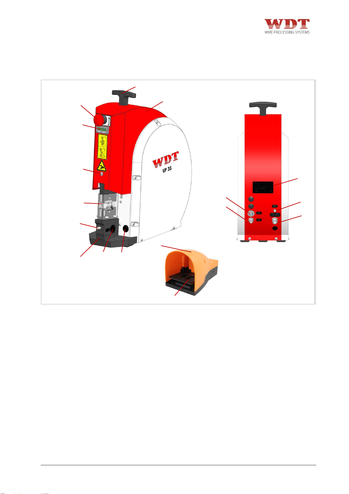
Pos.
Description
01
Pneumatic Parallel Crimp Machine UP 35
02
T-handle
03
Release Button
04
Electronic Piece Counter
05
Grease Nipple
06
Adapter CS 30/CK 100 for UP 35 (not in the scope of delivery)
07
Locking Device for Adapter Mounting
08
Adjusting screw (Height)
09
Clearance of basic setting
10
Light switch
11
A = control pressure
12
P = Compressed Air (foot pedal)
13
DC = DC Connection (Light)
14
Air max. = Compressed Air
15
Name plate with serial number
16
Pneumatic Foot Pedal
17
Safety Cover for Foot Pedal
17
16
01
03
02
04
05
06
07
08
09
10
11
12
13
14
15
Fig. 4.1
4 Technical Description
4.1 Operators Guide
UP35-4481N26000-02/15 – REV.B1 Page 42 / 63
Page 43
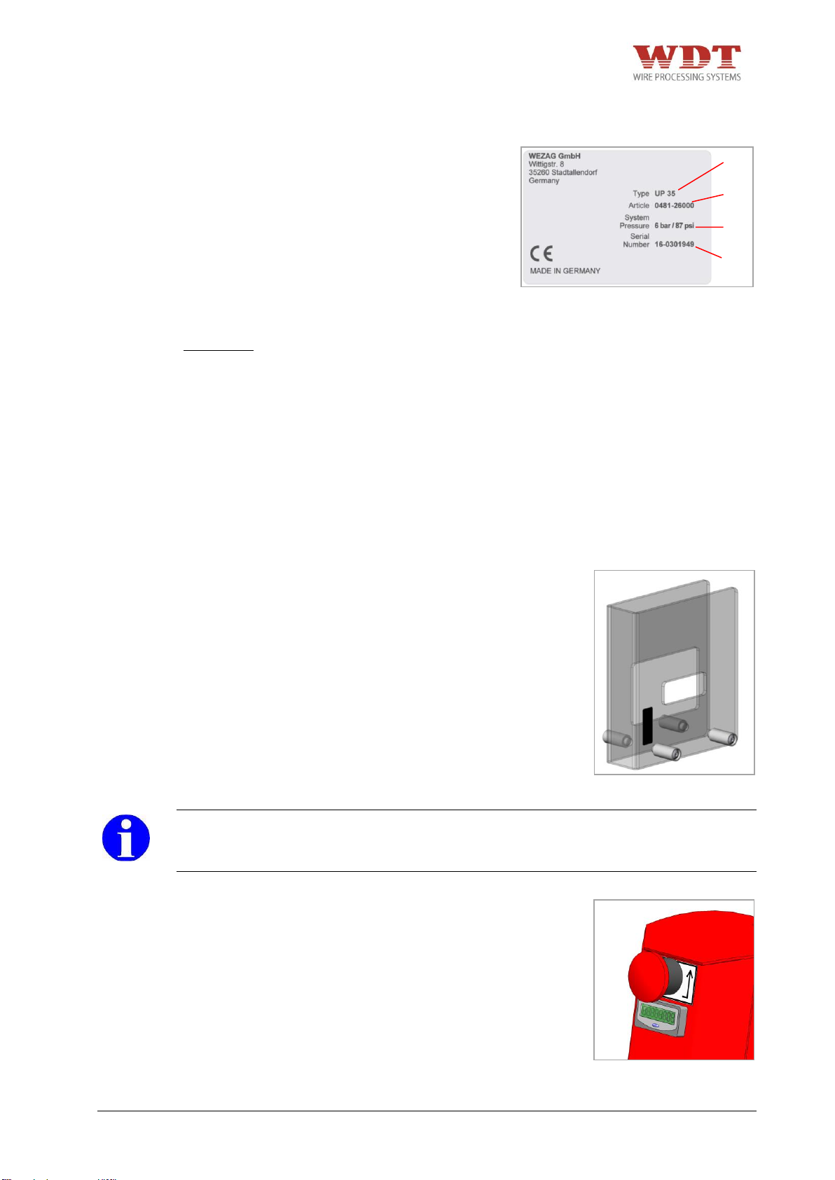
Fig. 4.4
Item
Description
1
Machine type
2
Article number
3
Air pressure
4
Serial number
Dimension:
Length overall:
390 mm (15,5”)
Width:
175 mm (7”)
Height:
440 mm (17,5”)
Weight with foot pedal:
approx. 25 kg (55 lbs)
Air consumption per stroke:
2.3 l
Air pressure:
max. 6 bar /87 psi
Crimp Force at 6 bar:
max. 35 kN (78683 lbf)
Stroke:
approx. 18 mm (0,7”)
Noise level:
62 dB (A)
Fig. 4.3
Fig. 4.2
1
2
3
4
4.2 Machine Identification
4.3 Technical Data
4.4 Safety Guard
Every adapter has a suitable safety guard (in
the scope delivery of the adapter).
Please find the adapters and suitable safety
guards in chapter 7.
INFORMATION
+ In case of an accident, because of mishandling or manipulation of the safety guard, the
manufacturer cannot be held liable for any resultant damage or injury.
4.5 Release Button
UP35-4481N26000-02/15 – REV.B1 Page 43 / 63
In case of a jammed die adapter caused by
operation or handling errors or wrongly
placed terminals the die adapter can be
opened as follows:
+ Press the release button.
Page 44
5 Transport and Installation
5.1 Transport
The weight of the pneumatic Parallel Crimp Machine UP 35 is approx. 20 kg (44 lbs).
Screw in the t-handle (in the scope of the delivery) on the machine.
CAUTION
+ Use the T handle for the transport by hand!
ATTENTION
+ Tubes must not be damaged.
+ Wear suitable safety shoes when transporting and installing the machine.
INFORMATION
+ The pneumatic Parallel Crimp Machine UP 35 has to be carried with the T handle for the
transport by hand.
5.2 Installation
ATTENTION
+ Position the pneumatic Parallel Crimp Machine UP 35 on a flat surface and assure the
stability of the machine. Ensure that the table or bench is stable enough to support the
machine in normal use.
+ Assure an appropriate table height. The table height is dependent on the position of the
operator, (work in sitting or standing position) according to prEN 894-4:2004, Table A.1.
+ Assure appropriate illumination of the working place. (EN 1837:1999 – chapter 4.2: “The
general value of illumination has to be 500 lx [...]").
INFORMATION
+ To reduce production noise or vibration, the machine can be placed on an insulating
rubber mat.
Place the foot pedal on the floor. No other place is allowed!
ATTENTION
+ Place the tubes on the floor or out of the way so that they do not cause a trip hazard.
+ Do not lay the foot pedal in aisles or walkways.
+ Assure free access to the operating elements of the machine, especially the foot pedal
and the release button.
+ Wear suitable safety shoes when transporting and installing the machine.
INFORMATION
+ To ensure fatigue-proof use, the user has to take a working position, where the machine
is at the right height and the foot pedal is accessible. The foot pedal has to be installed in
a stable position. The position of the foot pedal should be chosen in that way, that a free
access will be possible.
UP35-4481N26000-02/15 – REV.B1 Page 44 / 63
Page 45
6 Commissioning
6.1 Connecting to Compressed Air Supply
DANGER
+ Due to the risk of hand or finger injury, never try to reach into the machine before having
assured that the machine is disconnected from the air supply. Disconnect the air supply
before changing the safety guard, the adapter and the dies.
CAUTION
+ The pneumatic Parallel Crimp Machine UP 35 may only be set up and operated in perfect
technical condition, observing all the safety regulations and considering any possible
dangers.
+ The crimp machine is only allowed to be used with mounted dies, die adapter and the
suitable safety guard. Pay attention to the correct assignment of adapter to safety guard.
+ The crimp machine is only allowed to be used when it is in a completely functional
condition.
+ When working with the pneumatic Parallel Crimp Machine UP 35, do not wear loose
clothing, jewellery or long, loose hair that can get caught in the pneumatic Parallel Crimp
Machine UP 35.
+ Work with caution.
+ In cases of a machine malfunction, production must be stopped and the malfunction must
be fixed before continuing work with the machine.
+ Only one person is allowed to work on or with the machine at a time.
+ Only trained personal are allowed to work on or with the machine.
+ Assure free access to the operating elements of the machine, especially the foot pedal
and the release button. In the case of imminent danger immediately press the release
button. The release button must be within the direct reach of the operator. It must not be
covered.
+ It is only allowed to work with the specified air pressure.
UP35-4481N26000-02/15 – REV.B1 Page 45 / 63
Page 46
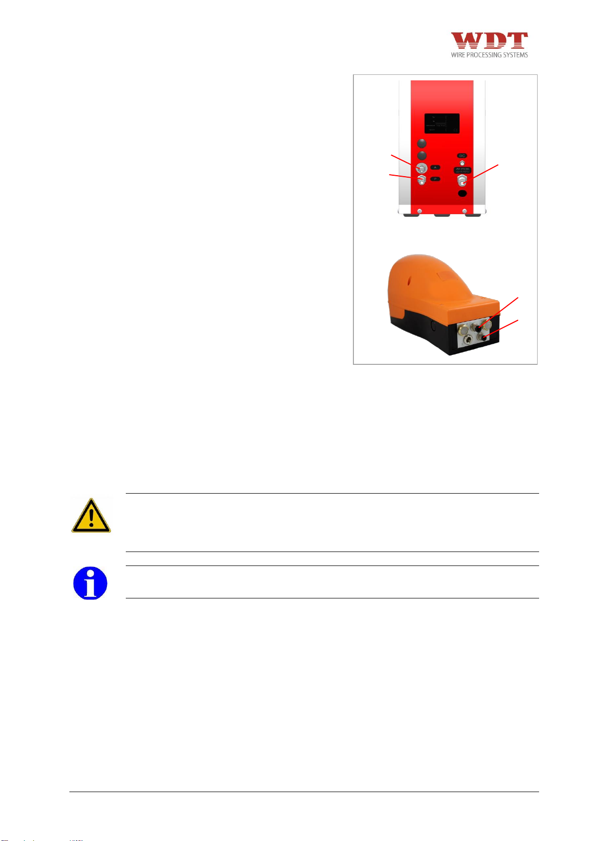
4 1 A
P
Air
MAX
Fig. 6.1
Connect the hose stem 1 on the foot
pedal with the compressed air hose Ø
6/4 mm to the connection P on the
pneumatic Parallel Crimp Machine UP
35.
Connect the hose stem 4 on the foot
pedal with the compressed air hose Ø
4/2 mm to the connection A on the
pneumatic Parallel Crimp Machine UP
35.
Use the pneumatic Parallel Crimp Machine UP 35 only with conditioned air (lubricated and
filtered). Standard Filter: 30 µm.
Connect AIR MAX. (Fig. 6.1) of the pneumatic Parallel Crimp Machine UP 35 to the main air
supply with the included black air hose Ø 8/6 mm.
Working Air Pressure: 6 bar/87 psi.
CAUTION
+ Connect compressed air supply with supplied compressed air tube (length 1m).
+ The machine can only be depressurized by disconnecting the machine from the main air
supply Air MAX (Fig. 6.1).
INFORMATION
+ Use only lubricated and filtered compressed air.
UP35-4481N26000-02/15 – REV.B1 Page 46 / 63
Page 47
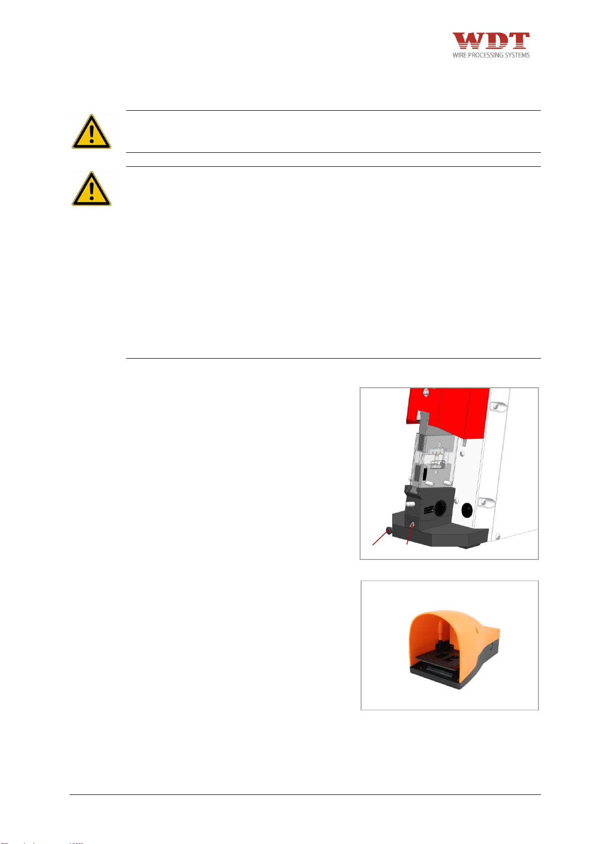
1
2
Fig. 6.2
Fig. 6.3
6.2 Control of the crimp Height
DANGER
+ Due to the risk of hand or finger injury, never try to reach into the machine before having
assured that the machine is disconnected from the air supply.
CAUTION
+ The crimp machine is only allowed to be used with mounted dies, die adapter and the
suitable safety guard. Pay attention to the correct assignment of adapter to safety guard.
+ The crimp machine is only allowed to be used when it is in a completely functional
condition.
+ When working with the pneumatic Parallel Crimp Machine UP 35, do not wear loose
clothing, jewellery or long, loose hair that can get caught in the pneumatic Parallel Crimp
Machine UP 35.
+ Work with caution.
+ In cases of a machine malfunction, production must be stopped and the malfunction must
be fixed before continuing work with the machine.
+ Only one person is allowed to work on or with the machine at a time.
+ Only trained personal are allowed to work on or with the machine.
+ It is only allowed to work with the specified working force.
+ Remove the plug 1 in front of the
adjusting screw 2.
+ Loosen the adjusting screw 2 (anti-
clockwise).
+ Push down the foot pedal and hold it.
+ Tighten the adjusting screw 2
(clockwise).
+ Release the foot pedal. In the event that
the machine does not open, abort the
crimp cycle by pressing the release
button.
UP35-4481N26000-02/15 – REV.B1 Page 47 / 63
Page 48
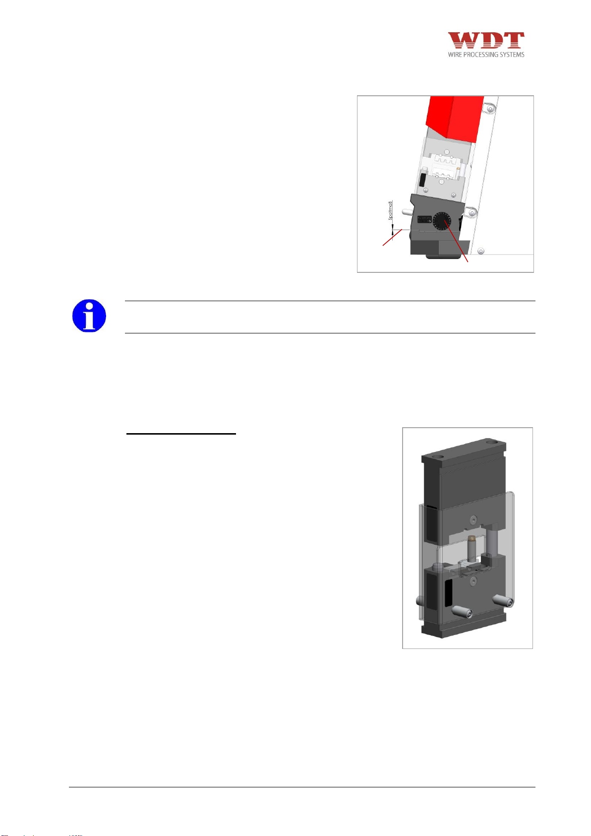
3
4
Fig. 6.4
Fig. 7.1
+ Remove the adjusting screw 2 again and
repeat adjusting procedure as described
above.
+ Turn the adjusting screw 2 by a ¼ of a
turn counter clockwise.
+ Balance the clearance 3 of the adjusting
mechanism with the clearance
specifications 4.
INFORMATION
+ Push the release button immediately, should the two dies not line up.
7 Tooling
7.1 Available Adapters
CS 30 / CK 100 Adapter
Inclusive safety guard for UP 35
WEZAG Art.-Nr. 1481-06010
UP35-4481N26000-02/15 – REV.B1 Page 48 / 63
Page 49
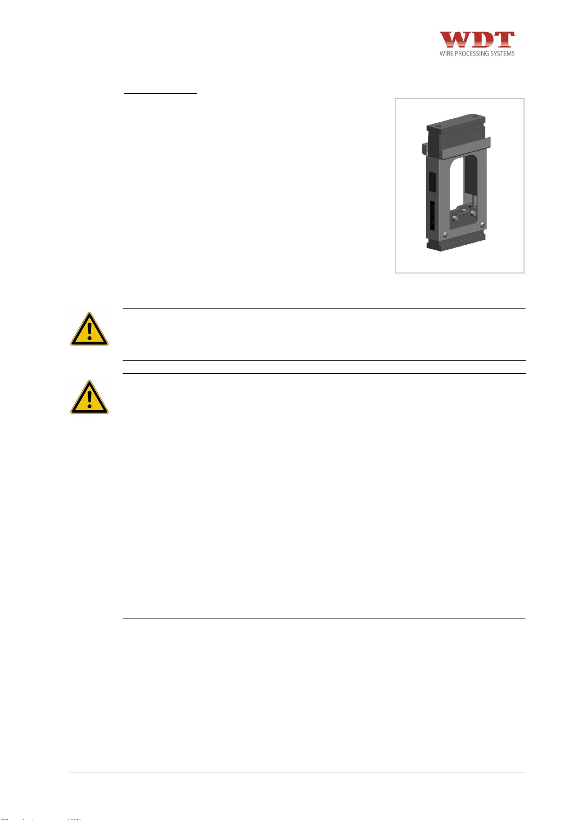
Fig. 7.2
CSV 10 Adapter
WEZAG Art.-Nr. 1481-06022
7.2 Adapter Assembly
DANGER
+ Due to the risk of hand or finger injury, never try to reach into the machine before having
assured that the machine is disconnected from the air supply. Disconnect the air supply
before changing the safety guard, the adapter and the dies.
CAUTION
+ The crimp machine is only allowed to be used with mounted dies, die adapter and the
suitable safety guard. Pay attention to the correct assignment of adapter to safety guard.
+ The crimp machine is only allowed to be used when it is in a completely functional
condition.
+ Before commissioning the machine, it is always important to check whether all safety
devices, especially the safety guards and die adapter, are installed and are functioning
correctly.
+ When working with the pneumatic Parallel Crimp Machine UP 35, do not wear loose
clothing, jewellery or long, loose hair that can get caught in the pneumatic Parallel Crimp
Machine UP 35.
+ Work with caution.
+ Only one person is allowed to work on or with the machine at a time.
+ Only trained personal are allowed to work on or with the machine.
+ Assure free access to the operating elements of the machine, especially the foot pedal
and the release button. In the case of imminent danger immediately press the release
button. The release button must be within the direct reach of the operator. It must not be
covered.
+ It is only allowed to work with the specified air pressure.
UP35-4481N26000-02/15 – REV.B1 Page 49 / 63
Page 50
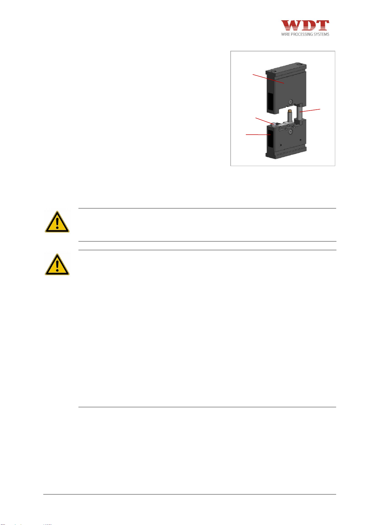
1 3 3
2
Fig. 7.3
+ Slide the upper die adapter 1 over the
alignment pillars 3 on the lower die
adapter 2 in a centered way.
7.3 Mounting of respecitve die set into the designed adapter
DANGER
+ Due to the risk of hand or finger injury, never try to reach into the machine before having
assured that the machine is disconnected from the air supply. Disconnect the air supply
before changing the safety guard, the adapter and the dies.
CAUTION
+ The crimp machine is only allowed to be used with mounted dies, die adapter and the
suitable safety guard. Pay attention to the correct assignment of adapter to safety guard.
+ The crimp machine is only allowed to be used when it is in a completely functional
condition.
+ Before commissioning the machine, it is always important to check whether all safety
devices, especially the safety guards and die adapter, are installed and are functioning
correctly.
+ When working with the pneumatic Parallel Crimp Machine UP 35, do not wear loose
clothing, jewellery or long, loose hair that can get caught in the pneumatic Parallel Crimp
Machine UP 35.
+ Work with caution.
+ Only one person is allowed to work on or with the machine at a time.
+ Only trained personal are allowed to work on or with the machine.
+ Assure free access to the operating elements of the machine, especially the foot pedal
and the release button. In the case of imminent danger immediately press the release
button. The release button must be within the direct reach of the operator. It must not be
covered.
+ It is only allowed to work with the specified air pressure.
UP35-4481N26000-02/15 – REV.B1 Page 50 / 63
Page 51
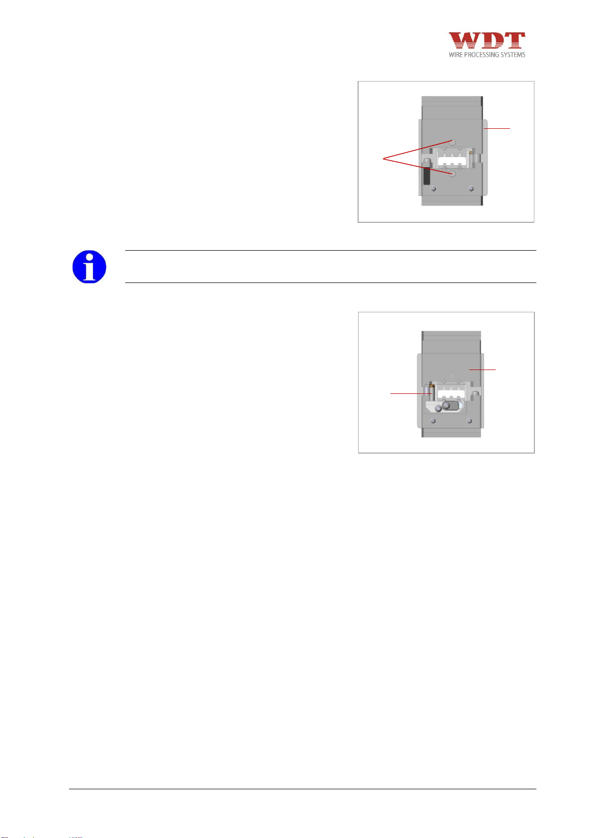
2
3
1
1
Fig. 7.4
Fig. 7.5
+ Remove safety guard 1.
+ Extract the upper and lower part of the
adapter.
+ Choose the correct die set.
+ Remove special screws 2 from the die.
+ Refer the upper and lower die to the right
adapter and fasten the screws.
INFORMATION
+ Control the right position of the die halves! The size of the profile should be in line!
+ If necessary put the locator on the locator
holder 3.
+ Slide the upper and lower adapter
together.
+ Install the safety guard 1.
UP35-4481N26000-02/15 – REV.B1 Page 51 / 63
Page 52
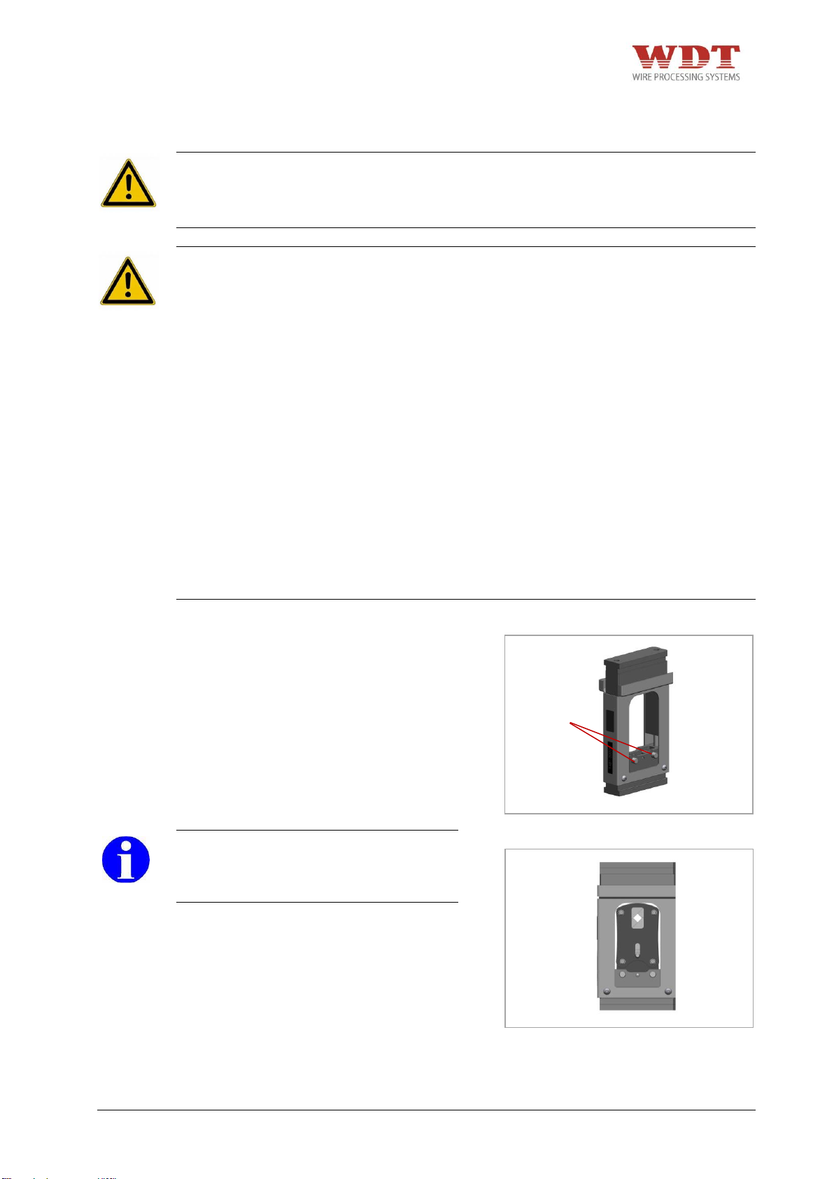
Fig. 7.6
Fig. 7.7
1
7.4 Mounting of respecitve tool head into the designed adapter
DANGER
Due to the risk of hand or finger injury, never try to reach into the machine before having
assured that the machine is disconnected from the air supply. Disconnect the air supply
before changing the safety guard, the adapter or the dies.
CAUTION
+ The crimp machine is only allowed to be used with mounted dies, die adapter and the
suitable safety guard. Pay attention to the correct assignment of adapter to safety guard.
+ The crimp machine is only allowed to be used when it is in a completely functional
condition.
+ Before commissioning the machine, it is always important to check whether all safety
devices, especially the safety guards and die adapter, are installed and are functioning
correctly.
+ When working with the pneumatic Parallel Crimp Machine UP 35, do not wear loose
clothing, jewellery or long, loose hair that can get caught in the pneumatic Parallel Crimp
Machine UP 35.
+ Work with caution.
+ Only one person is allowed to work on or with the machine at a time.
+ Only trained personal are allowed to work on or with the machine.
+ Assure free access to the operating elements of the machine, especially the foot pedal
and the release button. In the case of imminent danger immediately press the release
button. The release button must be within the direct reach of the operator. It must not be
covered.
+ It is only allowed to work with the specified air pressure.
+ Extract the upper and lower part of the
adapter as far as possible.
+ Choose the correct tool head.
+ Unlock and extract the pins 1 until stop.
+ Mount the tool head into the lower part of
the adapter and press the pins 1 until
stop.
INFORMATION
+ Control the right position of the die
halves! The size of the profile should be
in line!
+ Slide the upper and lower adapter together.
UP35-4481N26000-02/15 – REV.B1 Page 52 / 63
Page 53
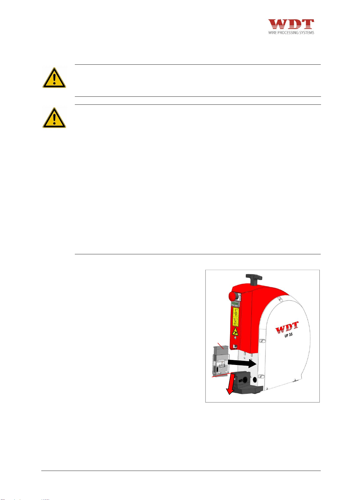
1
2
Fig. 7.8
7.5 Mounting adapter into the machine
DANGER
+ Due to the risk of hand or finger injury, never try to reach into the machine before having
assured that the machine is disconnected from the air supply. Disconnect the air supply
before changing the safety guard, the adapter and the dies.
CAUTION
+ The crimp machine is only allowed to be used with mounted dies, die adapter and the
suitable safety guard. Pay attention to the correct assignment of adapter to safety guard.
+ The crimp machine is only allowed to be used when it is in a completely functional
condition.
+ Before commissioning the machine, it is always important to check whether all safety
devices, especially the safety guards and die adapter, are installed and are functioning
correctly.
+ When working with the pneumatic Parallel Crimp Machine UP 35, do not wear loose
clothing, jewellery or long, loose hair that can get caught in the pneumatic Parallel Crimp
Machine UP 35.
+ Work with caution.
+ Only one person is allowed to work on or with the machine at a time.
+ Only trained personal are allowed to work on or with the machine.
+ Assure free access to the operating elements of the machine, especially the foot pedal
and the release button. In the case of imminent danger immediately press the release
button. The release button must be within the direct reach of the operator. It must not be
covered.
+ It is only allowed to work with the specified air pressure.
+ Disconnect pneumatic supply.
+ Press the locking device 1 downwards
and hold it.
+ Insert the die adapter 2 with mounted
safety guard into the adapter reception of
the machine. This process has to be
executed smoothly (without force),
otherwise the danger of canting will arise.
+ Release locking device 1.
+ If necessary move the die adapter 2 back
and forth, so that the locking device 1
can lock in place.
UP35-4481N26000-02/15 – REV.B1 Page 53 / 63
Page 54
8 Normal Operation / Production Cycle
DANGER
+ Due to the risk of hand or finger injury, never try to reach into the machine before having
assured that the machine is disconnected from the air supply. Disconnect the air supply
before changing the safety guard, the adapter and the dies.
CAUTION
+ The pneumatic Parallel Crimp Machine UP 35 may only be set up and operated in perfect
technical condition, observing all the safety regulations and considering any possible
dangers.
+ The crimp machine is only allowed to be used with mounted dies, die adapter and the
suitable safety guard. Pay attention to the correct assignment of adapter to safety guard.
+ Before commissioning the machine, it is always important to check whether all safety
devices, especially the safety guards and die adapter, are installed and are functioning
correctly.
+ When working with the pneumatic Parallel Crimp Machine UP 35, do not wear loose
clothing, jewellery or long, loose hair that can get caught in the pneumatic Parallel Crimp
Machine UP 35.
+ Work with caution.
+ In cases of a machine malfunction, production must be stopped and the malfunction must
be fixed before continuing work with the machine.
+ Only one person is allowed to work on or with the machine at a time.
+ Only trained personal are allowed to work on or with the machine.
+ Assure free access to the operating elements of the machine, especially the foot pedal
and the release button. In the case of imminent danger immediately press the release
button. The release button must be within the direct reach of the operator. It must not be
covered.
+ It is only allowed to work with the specified air pressure.
ATTENTION
+ Position the pneumatic Parallel Crimp Machines UP 35 on a flat surface and assure the
stability of the machine. Ensure that the table or bench is stable enough to support the
machine in normal use. During the utilization the machine has to be placed on a table or
a similar flat surface.
+ Place the foot pedal on the floor. No other place is allowed. The foot pedal must be
movable, so that the operator has the possibility to change his position for ergonomic and
production needs. Do not lay the foot pedal in aisles or walkways.
+ Place the tubes on the floor or out of the way so that they do not cause a trip hazard.
Crimp process without locator:
1. Insert the crimp contact in the die profile. Please pay attention to the correct profile
assignment and to the correct positioning within the crimp profile!
2. Insert the wire/cable which is stripped acc. to the specifications and position it for
crimping.
3. Press the foot pedal to start the crimp process.
4. Keep the foot pedal pressed until the crimp cycle is finished.
5. Remove crimped contact.
UP35-4481N26000-02/15 – REV.B1 Page 54 / 63
Page 55
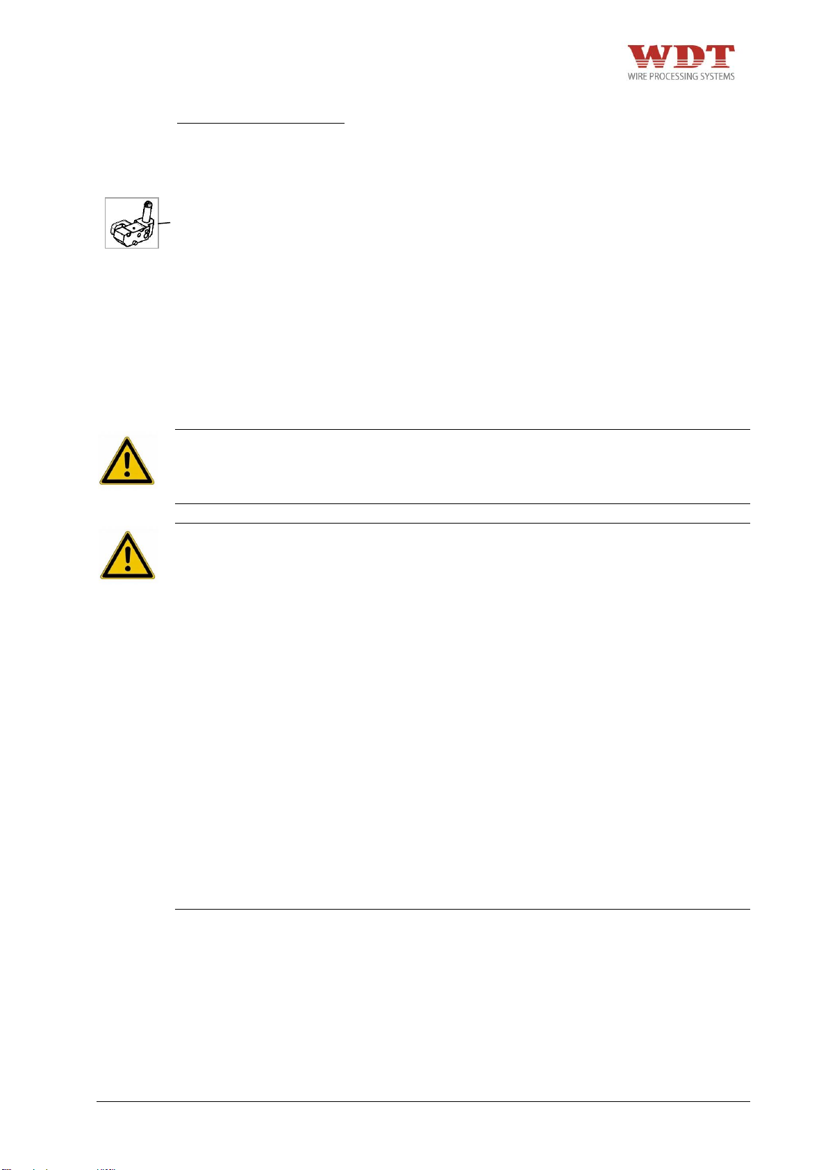
Crimp process with locator:
1. Flap out locator.
2. Insert the crimp contact in the die locator. Please pay attention to the correct profile
assignment and to the correct positioning within the crimp profile!
3. Close and lock locator.
4. Insert the wire/cable which is stripped acc. to the specifications and position it for
crimping.
5. Press the foot pedal to start the crimp process.
6. Keep the foot pedal pressed until the crimp cycle is finished.
7. Open locator and remove crimped contact.
9 Maintenance
DANGER
+ Due to the risk of hand or finger injury, never try to reach into the machine before having
assured that the machine is disconnected from the air supply. Disconnect the air supply
before changing the safety guard, the adapter and the dies.
CAUTION
+ The compressed air connection tube must not be longer than 1 m and has to have a
coupling connection.
+ Before starting maintenance, disassembly or repair work, the crimp machine must be
disconnected from air supply.
+ Maintenance work may be performed only by authorized and properly trained staff. The
housing and the covers in particular may only be removed by specially trained staff.
+ When working with the pneumatic Parallel Crimp Machine UP 35, do not wear loose
clothing, jewellery or long, loose hair that can get caught in the pneumatic Parallel Crimp
Machine UP 35.
+ The crimp machine is only allowed to be used when it is in a completely functional
condition.
+ The crimp machine is only allowed to be used with mounted dies, die adapter and the
suitable safety guard. Pay attention to the correct assignment of adapter to safety guard.
+ Work with caution.
+ Only one person is allowed to work on or with the machine at a time.
+ Assure free access to the operating elements of the machine, especially the foot pedal
and the release button. In the case of imminent danger immediately press the release
button. The release button must be within the direct reach of the operator. It must not be
covered.
+ It is only allowed to work with the specified air pressure
UP35-4481N26000-02/15 – REV.B1 Page 55 / 63
Page 56
9.1 Maintenance Plan
DANGER
+ Due to the risk of hand or finger injury, never try to reach into the machine before having
assured that the machine is disconnected from the air supply. Disconnect the air supply
before changing the safety guard, the adapter and the dies.
CAUTION
+ Before starting maintenance, disassembly or repair work, the crimp machine must be
disconnected from air supply.
+ Maintenance work may be performed only by authorized and properly trained staff. The
housing and the covers in particular may only be removed by specially trained staff.
+ When working with the pneumatic Parallel Crimp Machine UP 35, do not wear loose
clothing, jewellery or long, loose hair that can get caught in the pneumatic Parallel Crimp
Machine UP 35.
+ Work with caution.
+ Wear protective gloves and safety glasses during lubrication work. Please pay attention
to the safety instructions in the “safety data sheet” of the grease.
Regular maintenance and cleaning of the parts which can be reached without opening the
machine will prolong the life of the machine. Do not use rough materials to clean the
machine such as wire wool. The machine and or machine part should not be cleaned with
compressed air. The crimping machine as well as the machine parts must not be cleaned
with hard objects like scrapers, steel wool or similar. Vacuum heavily soiled parts and wear.
9.1.1 Daily
+ Visual inspection of the pneumatic Parallel Crimp Machine UP 35.
+ Check air pressure (max. 6 bar) of the house installation (manometer not in the scope of
the delivery).
+ Check oil-level of service unit of the house air supply (not in the scope of the delivery).
UP35-4481N26000-02/15 – REV.B1 Page 56 / 63
Page 57
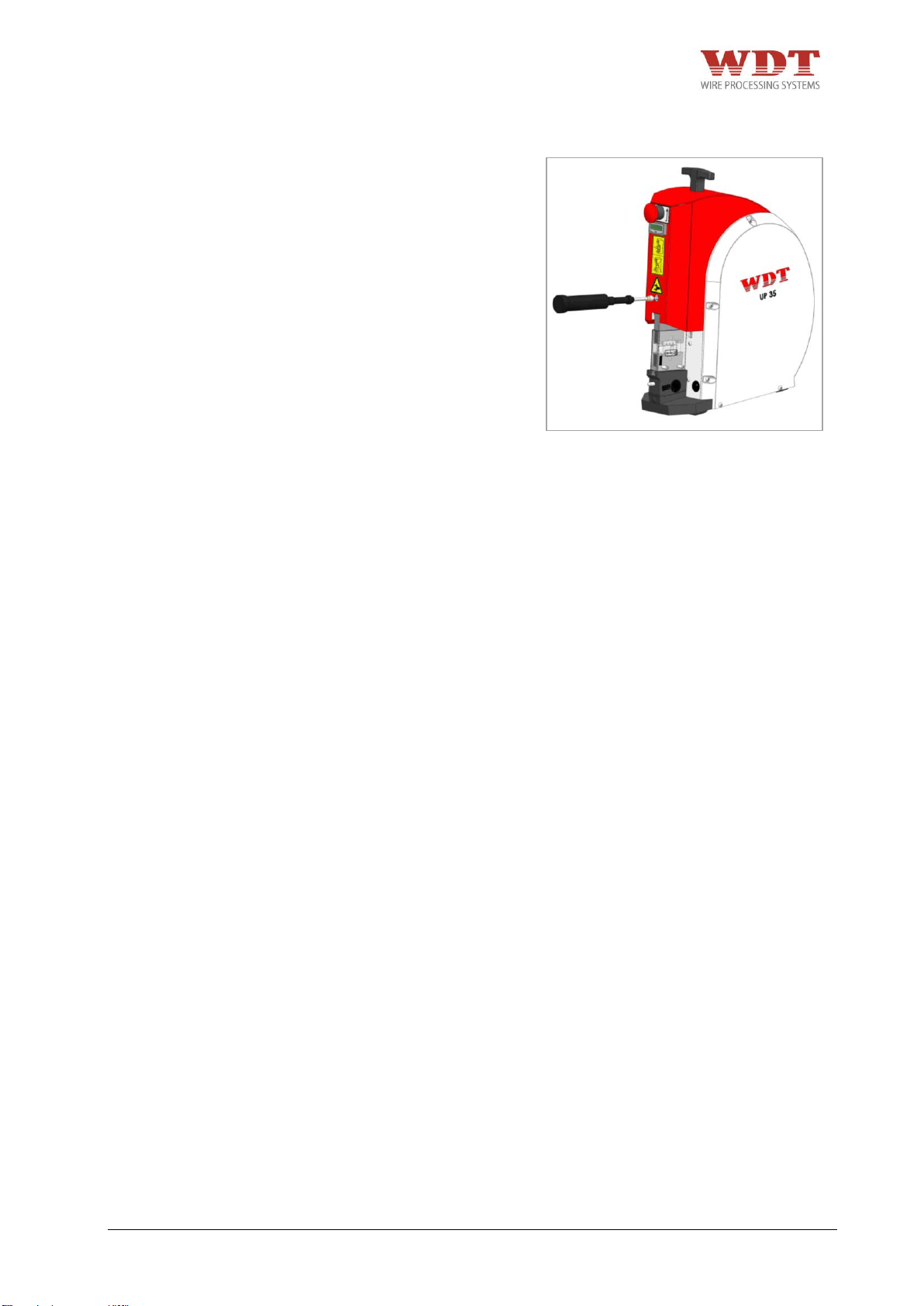
Fig. 9.1
9.1.2 Monthly
Lubricate the upper press shaft with the
supplied grease gun at the grease nipple
with one of the following greases:
+ Blaser Swiss Lube Art.-No. 00492-01 EP-
Universal Fett.
+ Molykote DX Paste
+ Dininol Fett LGM2, Art.-No. 27620
(Zellner+Gmelin GmbH & Co. KG)
Alternatively, lithium soap greases with the
following application areas can be used:
+ Sliding surfaces / friction contacts
+ High load applications
+ „Clean“ lubrication
+ Low speed
+ Base oil viscosity at 40°C (-4°F)
(DIN 51562): 110mm²/s
9.1.3 After every 25.000 crimp cycles or every 2 years
Please contact the producer or the distributor of the machine for inspections in the
recommended intervals.
Service address:
WEZAG GmbH
Werkzeugfabrik
Wittigstraße 8
35260 Stadtallendorf
Telephone: +49 6428 704-0
UP35-4481N26000-02/15 – REV.B1 Page 57 / 63
Page 58
10 Problem Handling and Fault Diagnostics
DANGER
+ Due to the risk of hand or finger injury, never try to reach into the machine before having
assured that the machine is disconnected from the air supply. Disconnect the air supply
before changing the safety guard, the adapter and the dies.
CAUTION
+ Before starting maintenance, disassembly or repair work, the crimping machine must be
disconnected from air supply.
+ Maintenance work may be performed only by authorized and properly trained staff. The
housing and the covers in particular may only be removed by specially trained staff.
+ When working with the pneumatic Parallel Crimp Machine UP 35, do not wear loose
clothing, jewellery or long, loose hair that can get caught in the pneumatic Parallel Crimp
Machine UP 35.
+ Work with caution.
+ Before commissioning the machine, it is always important to check whether all safety
devices, especially the safety guards and die adapter, are installed and are functioning
correctly.
+ Check the release button before starting the work on the crimp machine. In the case of
imminent danger immediately press the release button. The release button must be within
the direct reach of the operator. It must not be covered.
INFORMATION
+ In case of a blockade of the dies press the release button and disconnect the machine
from air supply.
In the event of a problem our customer service personnel will be able to help you.
Service address:
WEZAG GmbH
Werkzeugfabrik
Wittigstraße 8
35260 Stadtallendorf
Telephone: +49 6428 704-0
Please have the following information ready when you contact service.
+ Machine Type
+ Machine Serial Number
UP35-4481N26000-02/15 – REV.B1 Page 58 / 63
Page 59
11 Removal from Service, Demounting, Disassembly,
DANGER
+ Due to the risk of hand or finger injury, never try to reach into the machine before having
assured that the machine is disconnected from the air supply. The machine has to stand
still before changing the safety cover, adapter and the dies.
CAUTION
+ Before starting maintenance, disassembly or repair work, the crimping machine must be
disconnected from air supply.
+ Maintenance work may be performed only by authorized and properly trained personnel.
The housing and the covers in particular may only be removed by specially trained
personnel.
+ When working with the pneumatic Parallel Crimp Machine UP 35, do not wear loose
clothing, jewellery or long, loose hair that can get caught in the pneumatic Parallel Crimp
Machine UP 35.
+ Only one person is allowed to work on or with the machine at a time.
+ Work with caution.
12 Storage
Store the machine in the original box at room temperature.
13 Disposal
For the disposal of the pneumatic Parallel Crimp Machine UP 35, send it back to WEZAG
GmbH.
UP35-4481N26000-02/15 – REV.B1 Page 59 / 63
Page 60
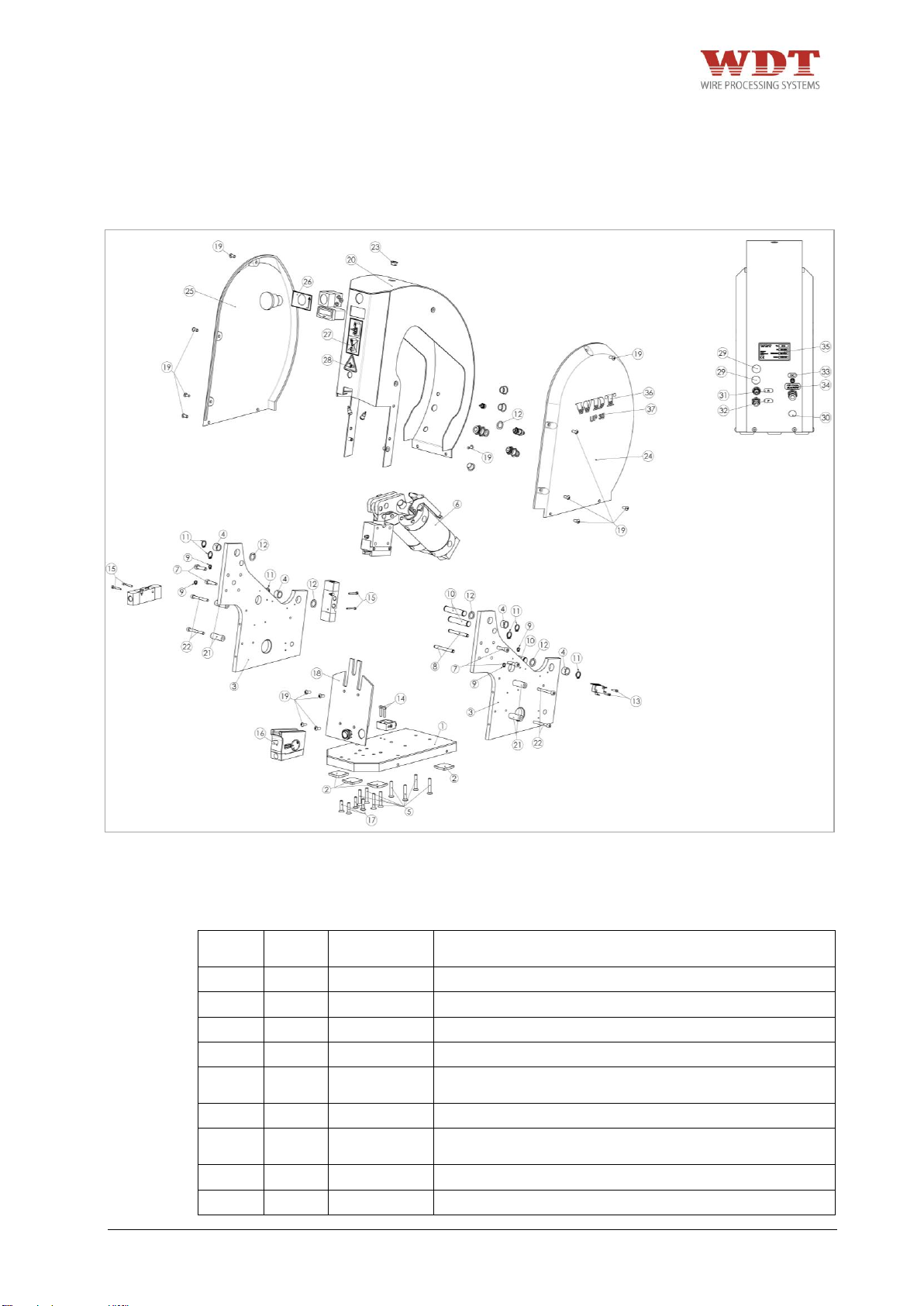
Pos.-
No.
Pieces
Art.-No.
Description
1 1 2481-02001
Basic plate
2 5 8480-89003
Adhesive base 31,7x31,7x6,1
3 2 2481-25006
Side panel
4 4 8481-02013
Cylinder Socket Ø16/12x10
5 8 8480-99069
Countersunk screw with hexagon socket M6x35
DIN7991
6 1 1481-26003
Cylinder Unit
7 4 8480-10111
Cylinder head screw with hexagon socket M6x25
DIN912
8 2 2481-02023
Bolt Ø6h9 x 60
9 4 8481-02007
Retaining Ring DIN 471-6x0,7
Fig. 14.1
14 Exploded View Drawing, Spare Part List, Pneumatic Diagram
14.1 Exploded View Drawing
14.2 Parts List Exploded View Drawing
UP35-4481N26000-02/15 – REV.B1 Page 60 / 63
Page 61

Pos.-
No.
Pieces
Art.-No.
Description
10
3
2480-89024
Drive Shaft-1296-18
11
6
8480-99161
Circlip DIN 471-12x1
12
5
8481-25007
Shim Ring Ø12/18x0,5 DIN988
13
2
8480-99121
Cylinder head screw with hexagon socket M3x14
DIN912
14
2
8180-23002
Cylinder head screw with hexagon socket M4x20
DIN912
15
4
8480-89010
Cylinder head screw with hexagon socket M3x25
DIN912
16
1
1481-25002
Adjusting Unit
17
4
8481-02004
Countersunk screw with hexagon socket M6x25
DIN7991
18
1
2481-25005
Cover plate
19
16
8481-02008
Fillister head screw with hexagon M5x12 (galvanized
blue)
20
1
1481-25001
Cover complete
21
4
2481-02020
Spacer bushing 12,00/5,3x33,5
22
4
8480-99127
Cylinder head screw with hexagon socket M5x45
DIN912
23
1
8481-02001
Locking Screw EVSG M12 - RAL 9005
24
1
2481-02017
Cover right
25
1
2481-02018
Cover left
26
1
5481-02002
Adhesive label "Release"
27
1
5480-88002
Adhesive label "Hinweis Fingerschutz"
28
1
5480-81005
Adhesive label „Warning of Hand Injuries“
29
2
8481-06001
Decorative plug Ø14,9/18,5 black
30
1
8201-00002
Cover plug Ø14,9/18,5 black
31
1
5481-03003
Label „A“
32
1
5481-02006
Label „P“
33
1
5481-03002
Label „DC“
34
1
5481-02007
Label „Air-max.“
35
1
4481-26100
Machine identification label
36
2
5480-81027
Label "WDT" red
37
2
5481-06001
Label "UP35" black
38
1
1481-26002
Pneumatic complete
39
1
1481-25009
Electric complete
The repair of the machine has to be executed by trained personnel. Please contact the
producer or distributor of the machine!
Service address:
WEZAG GmbH
Werkzeugfabrik
Wittigstraße 8
35260 Stadtallendorf
Telephone: +49 6428 704-0
UP35-4481N26000-02/15 – REV.B1 Page 61 / 63
Page 62
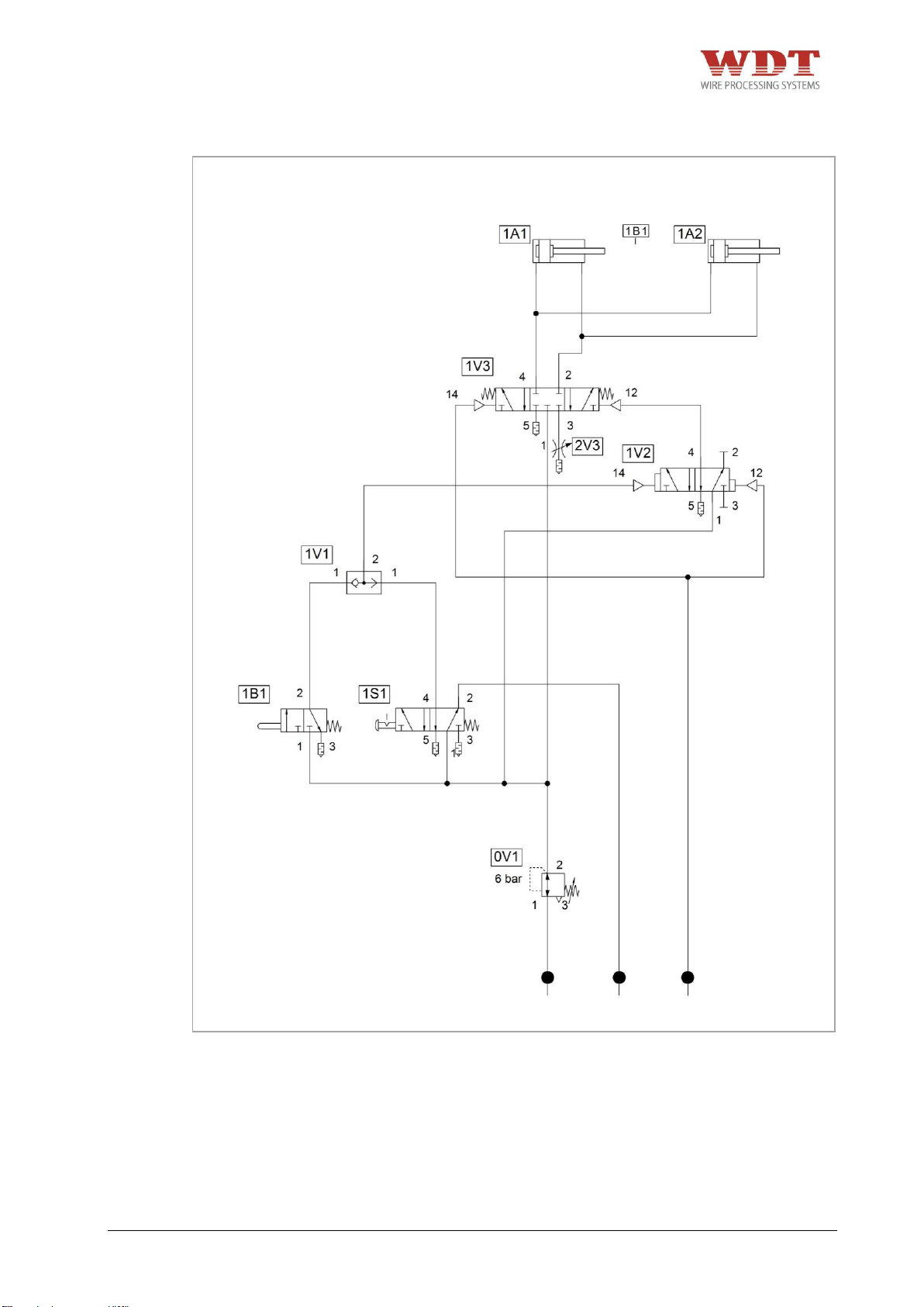
Fig. 14.2
14.3 Pneumatic Diagram
UP35-4481N26000-02/15 – REV.B1 Page 62 / 63
Page 63

ID
Pieces
Article Number
Description
1V1
1
8480-88086
Oder valve
1V2
1
8480-85002
5/2 pneumatic valve
1V3
1
8480-88089
5/3 pneumatic valve
1B1
1
8480-88005
Button (1A1 extended)
0V1
1
8481-03003
Pressure control valve, adjustable
2V3
1
8480-88073
Throttle valve
1S1
1
8481-03042 +
8481-03018
Palm switch red incl. Valve
14.4 Parts List Pneumatic
The repair of the machine has to be executed by trained personnel. Please contact the
producer or distributor of the machine!
Service address:
WEZAG GmbH
Werkzeugfabrik
Wittigstraße 8
35260 Stadtallendorf
Telephone: +49 6428 704-0
14.5 Accessories overview for re orders
1. Pneumatic foot pedal with cover order no.: 1481-03033
2. Air hose set order no.: 1881-03001
3. Hexagon wrench key set order no.: 1881-02002
4. Grease gun order no.: 9480-88019
5. T-handle order no.: 8481-02005
6. Power supply with changeable adapters order no.: 1881-03005
UP35-4481N26000-02/15 – REV.B1 Page 63 / 63
 Loading...