


Source | Mute | 2ch
(HDMI Out Audio)
MEDIA OVER IP SYSTEM
B-900-MOIP-4K-CTRL
B-900-MOIP-4K-TX
B-900-MOIP-4K-RX
NETWORKING GUIDE

2
INTRODUCTION
This guide details the networking requirements, recommendations and limitations when
conguring a Binary B-900 Series Media over IP system (MoIP) system which can be used to
deploy MoIP on any compatible network switch. Also, you will nd the simple steps to congure
an Araknis 210 Series PoE and 310 Series PoE Layer 2 managed switch in a single switch MoIP
deployment as well as basic guidelines, requirements for single and multiple switch MoIP
setups.
IMPORTANT: Network switches directly connected to MoIP Transmitters and MoIP Receivers
should always be congured prior to connecting any of these components.
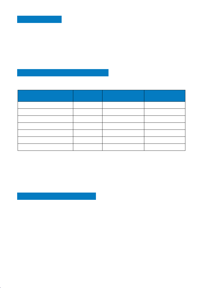
RECOMMENDED NETWORK SWITCHES
Single Switch Deployments
Araknis Switch Model Ethernet
Ports (1 Gbps)
AN-210-SW-F-48-PoE 48 4 375
AN-210-SW-F/R-24-PoE 24 2 190
AN-210-SW-F/R-16-PoE 16 2 130
AN-210-SW-F/R-8-PoE 8 2 65
AN-310-SW-F/R-24-PoE 24 2 375
AN-310-SW-F/R-16-PoE 16 2 250
AN-310-SW-F/R-8-PoE 8 2 130
SFP Ports (1 Gbps) PoE Budget (Watts)
Multiple Switch Deployments
Araknis switches do NOT support multiple switch setups at this time. SnapAV does not
recommend a particular switch as an alternative to Araknis. In setups where MoIP transmitters
and MoIP receivers must be connected on multiple extended switches, multiple gigabit uplinks
between switches is required. Numerous network switch manufacturers offer switches with
multiple gigabit uplink/SFP ports to support multiple switch deployments.
SELECTING A NETWORK SWITCH
Network Switch Requirements
The Ethernet PoE switch selected is critical for the optimal performance of the MoIP system.
Araknis 210 Series and 310 Series PoE switches are recommended. Switch functionality,
capability and reliability can vary greatly from one manufacturer to the next. Conguration
will vary by manufacturer. Refer to the manufacturers user manual to enable required features
to support MoIP. Some brands of switches may have limited support of required functions,
bandwidth across the entire switch, and necessary total PoE power to support all MoIP
Transmitters and Receivers.
3

Network Switch Minimum Requirements
A network switch selected for a MoIP system must meet the requirements below or support
the following features:
Single Switch Deployments
• Layer 2 or Layer 3 Managed
• 1 Gigabit Ethernet Port Throughput (minimum)
• Simultaneous 7.5 Watts PoE across all ports (minimum)
• Multicast forwarding or ltering
• IGMP Snooping
• IGMP Querier
• Jumbo Frames (8000 bytes or larger)
• Also known as Jumbo Packets or Maximum Transmission Unit
If a multiple switch deployment is required, the switches must also support:
• Dynamic Multicast Router Port
• Forwarding Unknown Multicast to Multicast Router Port Only
Note: It is highly recommended that the above features be applied to all network switches on
the same LAN as MoIP as a best practice. This is not required; however, highly recommended.
Number of Ports
Given the exibility and scalability of Binary’s B-900 Series Media over IP system, it is
recommended that a switch with more Ethernet ports than needed for the MoIP system be
used to allow quick addition of devices in the future. Utilizing an Araknis 210 Series 48-port
PoE switch, a MoIP system maximum size limit is 47 total MoIP Transmitters and MoIP
Receivers. Larger systems utilizing other manufacturer’s switch is possible in both single and
multiple switch deployments.
When calculating the size of switch needed, count one port for each the following devices:
1. Number of sources (MoIP Transmitters)
2. Number of displays (MoIP Receivers)
3. MoIP Controller
4. LAN connection to main network for OvrC (if applicable)
Power
The MoIP Transmitters and MoIP Receivers can be powered by Power-over-Ethernet (PoE)
or a separate 12V power supply (not included). The separate power supply is available only
as a replacement part only. TX and RX will each utilize no more than 7.5 watt of power. Snap
AV recommends using PoE to power the MoIP TX and RX units. The MoIP Controller is NOT
powered by PoE and requires the use of the included 12V power supply.
4

MoIP System Network Setups
MoIP Transmitter
MoIP Transmitter
Single switch MoIP network congurations are supported by Araknis 210 PoE and 310 PoE
Series switches. Integrators familiar with the above requirements and the conguration of
stackable and cascaded switches with multi-gigabit uplinks will be able to create very large
MoIP deployments.
Single Switch
Dedicated MoIP Switch (RECOMMENDED)
MoIP Transmitter
MoIP Receiver
MoIP Controller
Network
+5VDC
Shared MoIP Switch
MoIP Receiver
MoIP Controller
Network
+5VDC
MoIP on Main LAN Switch
MoIP Receiver
MoIP Controller
Network
+5VDC
Dedicated MoIP Switch Main LAN Switch
9 11 13 15
10 12 14 16
9 11 13 15
10 12 14 16
MoIP Switch Main LAN Switch
To other network device
Main LAN Switch
9 11 13 15
10 12 14 16
9 11 13 15
10 12 14 16
9 11 13 15
10 12 14 16
To other network device
Multiple Switches
Please refer to your network switch manufacturers’ documentation to enable the critical
features for optimal performance in multiple switch MoIP network congurations. We
recommend Pakedge MS series switches, which we have a setup guide for.
Bandwidth considerations are critically important. The maximum number of MoIP
Transmitters which can be supported by a given network topology is limited by the lowest
5

bandwidth link in the network. Typically, this will be the link between switches. MoIP Receivers
have no impact on available bandwidth. The bandwidth requirements of other devices on the
network should also be considered.
Each MoIP Transmitter consumes 250-850 Mbps (4K) or 150-750 Mbps (1080p) of the
available bandwidth. The lowest bandwidth link limitation applies no matter to which switch
in the multiple switch setup the transmitter is connected. To calculate the required bandwidth
needed to support the desired number of MoIP Transmitters, multiply the number of MoIP
Transmitters by 0.85. This will give you the bandwidth in Gbps. For example, 10 MoIP
transmitters would require 8.5 Gbps. In the diagrams below, X Gbps indicates a multiple gigabit
connection between switches. The throughput of this uplink must accommodate, for this
example, 8.5 Gbps for the MoIP system to operate optimally.
Cascaded Switches
MoIP Transmitter
MoIP Receiver
MoIP Receiver
Network
+5VDC
MoIP Controller
Stacked Switches
MoIP Receiver
MoIP Receiver
MoIP Transmitter
MoIP Transmitter
MoIP Transmitter
xGbps
9 11 13 15
10 12 14 16
9 11 13 15
10 12 14 16
9 11 13 15
10 12 14 16
X Gbps
9 11 13 15
10 12 14 16
MoIP Extended Switch
xGbps
MoIP Core Switch
MoIP Switch 1
MoIP Core Switch
9 11 13 15
10 12 14 16
MoIP Core
Switch Stack
9 11 13 15
10 12 14 16
To other network device
Main LAN Switch
To other network device
To other network device
Main LAN Switch
Network
MoIP Controller
+5VDC
To other network device
6

ARAKNIS 210/310 PoE SERIES CONFIGURATION
1. Congure Network Switch
Steps below use an Araknis 210 PoE or 310 PoE Series switch as an example
1. Factory default the MoIP switch to be used for all MoIP Components (not necessary for
new switches). Press and hold the reset button for 10—15 seconds until the Status LED
ashes once. This will reboot the switch and reset to factory settings.
2. Connect the dedicated MoIP switch directly to your Main LAN switch. (The Main LAN
switch is the main network switch into which all other switches and network devices are
connected. The Main LAN switch is the only switch connected to the router. A dedicated
MoIP switch is preferred but not required. See ‘Network Guide’ for more information.)
3. Access the local of the MoIP Switch.
Note: Default login in credentials for an Araknis which are araknis / araknis. The Default IP
address is 192.168.20.254.
2. Enable IGMP Snooping
Choose ADVANCED > MULTICAST > IGMP SNOOPING, then check options as follows:
1. Status: Enabled
2. Version: V2
3. Report Suppression: Enabled
4. Unregistered IPMC Forward Action: Drop
5. IGMP Snooping Status: Enabled
6. Fast Leave: Disabled
7. Querier State: Enabled
8. Querier Version: V2
9. Router Settings > Router Ports Auto-Learned: Enabled
Click Apply to save these settings
7
3. Verify Jumbo Frame
Pi
Pi
Pi
Pi
TIA/EIA Standard 568-B (Gold Pins Facing Up)
Choose SETTINGS > PORTS, then verify Jumbo Frame is set to greater than 8,000 Bytes. The
default value is 9216 the maximum is acceptable.
ADDITIONAL SUPPORT INFORMATION
• Each transmitter and receiver can be connected to the MoIP switch with up to 328ft / 100m
of category cable.
• CAT5e cabling is sufcient to support the MoIP system; however, with all networking installs
utilizing shielded CAT5e, CAT6, CAT6A or CAT7 is recommended to minimize potential for
interference from environmental factors.
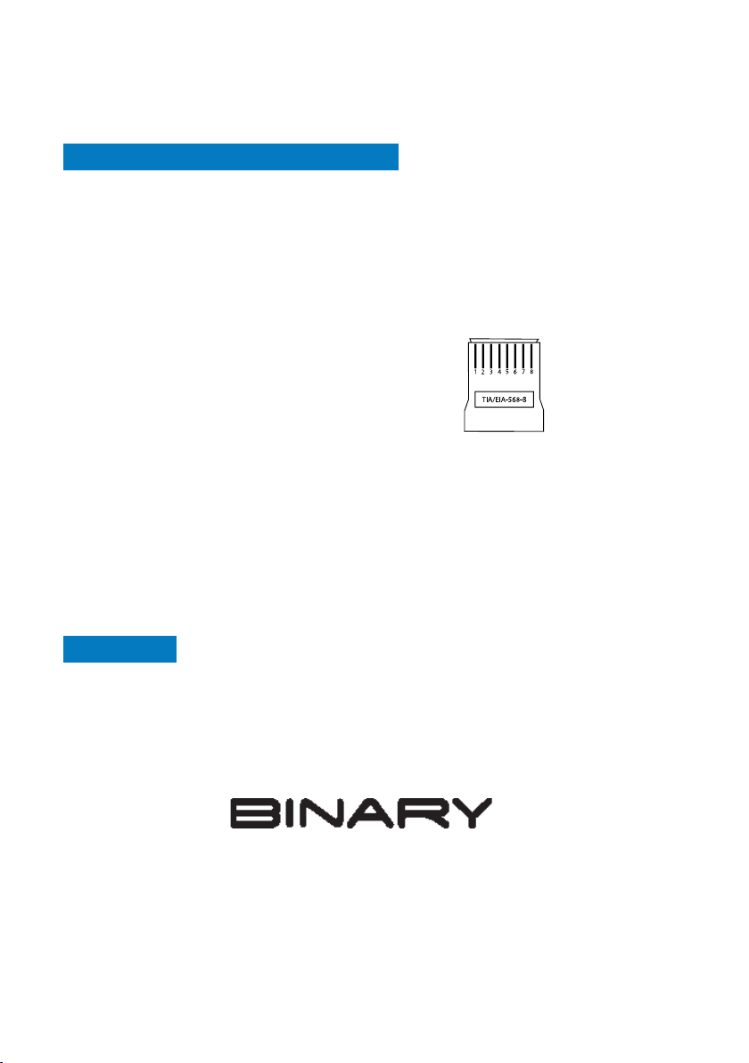
• Each category cable should be terminated to the T-568B specication. TIA/EIA Standard
568-B (Gold Pins Facing Up)
n 1White/OrangePin 5White/Blue
n 2OrangePin 6Green
n 3White/Green Pin 7White/Brown
n 4Blu ePin 8Brown
Two (2) Year Limited Warranty
This Binary product has a Two-Year Limited Warranty. This warranty includes parts and labor
repairs on all components found to be defective in material or workmanship under normal
conditions of use. This warranty shall not apply to products that have been abused, modied or
disassembled. Products to be repaired under this warranty must be returned to a designated
service center with an assigned return authorization number (RA). Contact technical support
for an RA number.
SUPPORT
Need Help? Contact Tech Support!
If you need further clarication, please call tech support at 866.838.5052, or email
support@snapav.com. For other information, instructional videos, support documentation, or
ideas, visit our website and view your item’s product page at
www.snapav.com.
Copyright ©2021, Wirepath Home Systems, LLC. All rights reserved. Control4 and Snap AV and
their respective logos are registered trademarks or trademarks of Wirepath Home Systems, LLC,
dba “Control4” and/or dba “SnapAV” in the United States and/or other countries. Snap AV and
Binary are also registered trademarks or trademarks of Wirepath Home Systems, LLC. Other names
and brands may be claimed as the property of their respective owners. All specications subject to
Rev: 210405-1302
change without notice.
 Loading...