

Page 1
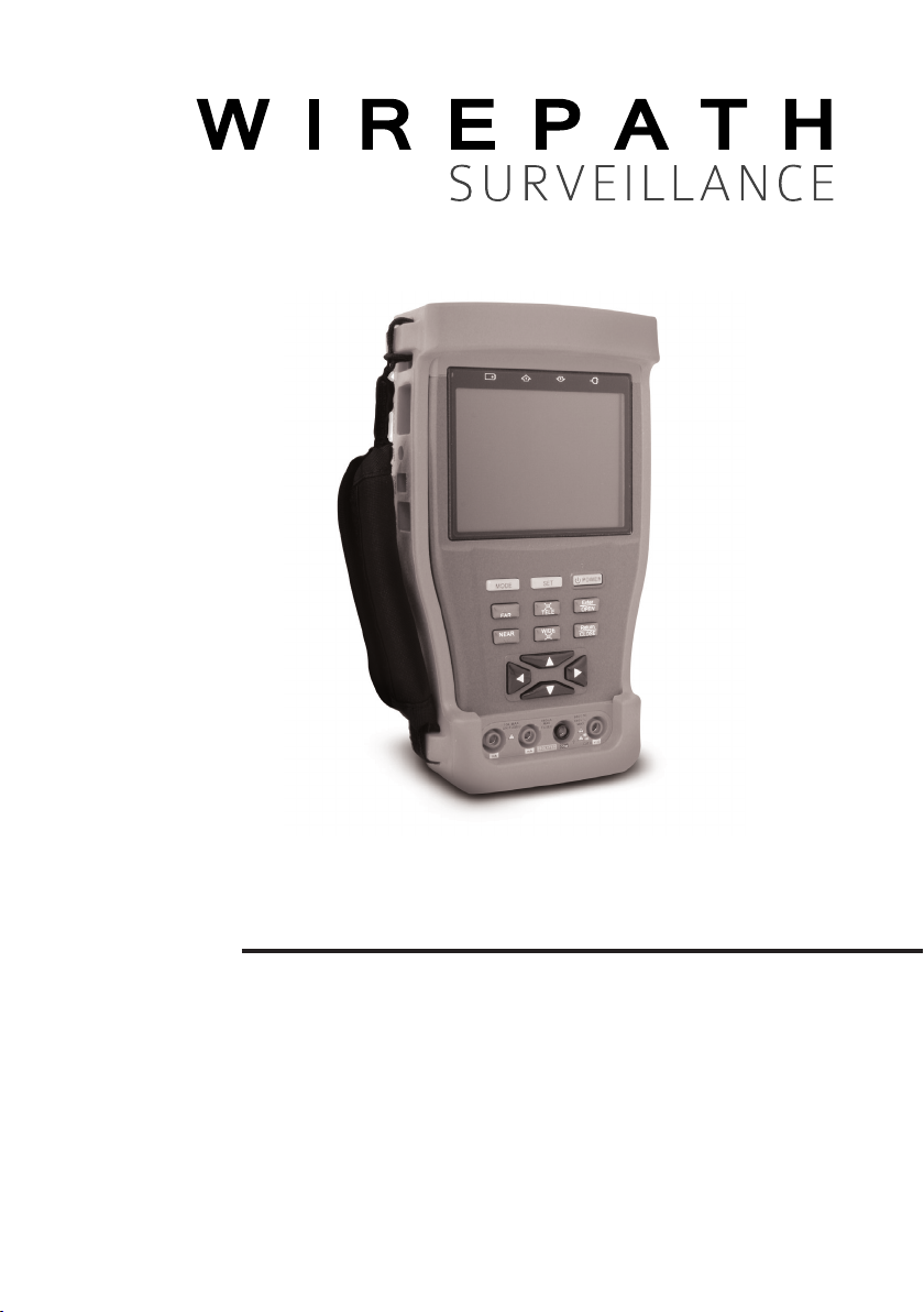
WPS-CCTV-TESTER
MULTI-FUNCTION
TESTER
Page 2

Page 3

CONTENTS
1 OVERVIEW........................................................................................................5
1.1 Features ......................................................................................................... 5
1.2 Package Contents ....................................................................................... 5
2 FRONT AND REAR PANEL ................................................................................6
2.1 Front Panel .................................................................................................... 6
2.2 Side Panels .................................................................................................... 8
3 PREPARATION FOR USE ...................................................................................9
3.1 Installing the Battery .................................................................................... 9
3.2 Charging the Battery ................................................................................... 9
3.3 Power Button ................................................................................................ 9
4 OPERATION ...................................................................................................... 9
4.1 PTZ Controller ................................................................................................ 9
4.1.1 PTZ Connections ........................................................................................ 9
4.1.2 PTZ Settings ................................................................................................. 10
4.1.3 Camera OSD ............................................................................................. 11
4.1.3.1 Wirepath Surveillance Cameras OSD .................................................. 11
4.1.3.2 PTZ OSD ................................................................................................... 11
4.1.4 PTZ Continuing Scan Test .......................................................................... 11
4.2 Video Setting ................................................................................................ 12
4.3 Colorbar Generator ..................................................................................... 12
4.4 UTP Cat5e/6 Cable Tester .......................................................................... 13
4.5 Data Monitor ................................................................................................ 13
4.6 Device Setting .............................................................................................. 14
4.7 PTZ Address Scanning .................................................................................. 14
4.8 Digital Multi-Meter ........................................................................................ 15
4.8.1 Multi-Meter ................................................................................................. 15
4.8.2 Multi-Meter Symbols .................................................................................. 15
4.8.2.1 DC Voltage Measuring .......................................................................... 15
4.8.3 AC Voltage Measuring ............................................................................. 16
4.8.4 DC Current Measuring .............................................................................. 16
4.8.5 AC Current Measuring .............................................................................. 17
4.8.6 Resistance Measuring ............................................................................... 17
4.8.7 Continuity Testing ...................................................................................... 18
4.8.8 Diode Testing ............................................................................................. 18
4.8.9 Capacitance Measuring ......................................................................... 18
4.8.10 DC12V 1A Power Output ....................................................................... 19
4.8.11 Audio Input Test ....................................................................................... 19
5 SPECIFICATIONS .............................................................................................. 20
5.1 6.1 General Specications .......................................................................... 20
5 5.2 Multi-Meter Specications ........................................................................ 21
6 WARRANTY.......................................................................................................23
Page 4
IMPORTANT SAFETY INSTRUCTIONS
WARNING: To reduce the risk of re or electric shock, do not expose this
apparatus in or near rain or moisture.
1. Read and keep these instructions for future reference.
2. Do not use this apparatus near water.
3. Clean only with a dry cloth.
4. Protect the power cord from being walked on or pinched particularly
at plug, convenience receptacles, and the point where it exits from the
apparatus.
5. Only use attachments/accessories specied by the manufacturer.
6. To completely disconnect this equipment from the AC mains, disconnect the
power supply cord plug from the AC receptacle.
7. This is CLASS II apparatus with double insulation, and no protective earth
provided.
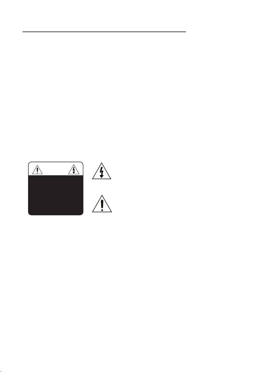
The lightning ash with arrowhead symbol, within an
CAUTION
CAUTION: TO REDUCE THE RISK
OF ELECTRICAL SHOCK, DO
NOT REMOVE COVER. NO USER
SERVICEABLE PARTS INSIDE.
REFER SERVICING TO QUALIFIED
SERVICE PERSONNEL.
equilateral triangle, is intended to alert the user to the
presence of uninsulated dangerous voltage within the
product’s enclosure that may be of sufcient magnitude
to constitute a risk of electric shock to persons.
The exclamation point within an equilateral triangle is
intended to alert the user to the presence of important
operating and maintenance (servicing) instructions in
the literature accompanying the appliance.
Page 5

WPS-CCTV-TESTER Users Manual
1 OVERVIEW
The WPS-CCTV-TESTER was developed for the on-site installation and
maintenance of surveillance video monitoring systems. It can be used for
displaying video to set up the scene for a camera (positioning, zoom, focus),
testing data and controlling PTZ, generating video pattern images, capturing
RS485 and testing Cat5e/6 cable. Digital multi-meter for voltage and continuity
testing is also available. The easy operation and portability makes it simple for
the CCTV technician to install and maintain CCTV systems, improving work
efciency and reducing labor costs.
1.1 Features
• 3.5”Color LCD Display (960(H)× 240 (V) resolution)
• Video Level testing(video signals measured in IRE or mV)
• 12VDC 1A power output for camera
• Audio input testing
• Digital multi-meter (voltage, current, resistance and capacitance)
• PTZ control - Pan/tilts the P/T unit, zooms in/out the lens, adjusts the focus,
aperture, sets and selects a preset position
• PTZ continuing rotate test
• Video display - Automatically adapts and displays the video format of NTSC/
PAL
• LCD Brightness/Contrast/Color Saturation adjustments
• Video Generating - PAL/NTSC multi-system colorbar video generator
• Data analyst. Captures and analyzes RS485 controlling data
• Cable testing -Verify connector pin mapping and continuity of Cat5e/6 or
telephone cable
• Supports RS232 ,RS485 and RS422; baud rate ranging from 150, to 19200bps
• Multi-protocol - Supports more than twenty PTZ protocols such as PELCO-D
• PTZ address scanning, search up the ID of PTZ camera
• Lithium Ion Polymer Battery (3.7V DC 3000mAh). Up to 12 hours for normal use
after charging for 4 hours
1.2 Package Contents
(1) WPS-CCTV-TESTER
(1) Cat5e/6 cable Tester
(1) BNC Cable
(1) Safety Strap
(1) Power Supply
(1) Lithium Ion Polymer Battery
(2) Multi-Meter Test Leads (1 Red / 1 Black)
(1) RS485 Data Cable with 2 conductor plug
(1) Audio Connection Cable with 3.5mm Stereo plug and Clips
(1) Camera Power Cable
(1) UTP Cat5e/6 Cable Tester
(1) Operation Manual
© 2011 Wirepath Surveillance
5
Page 6
WPS-CCTV-TESTER Users Manual
2 FRONT AND REAR PANEL
2.1 Front Panel
6
Page 7

WPS-CCTV-TESTER Users Manual
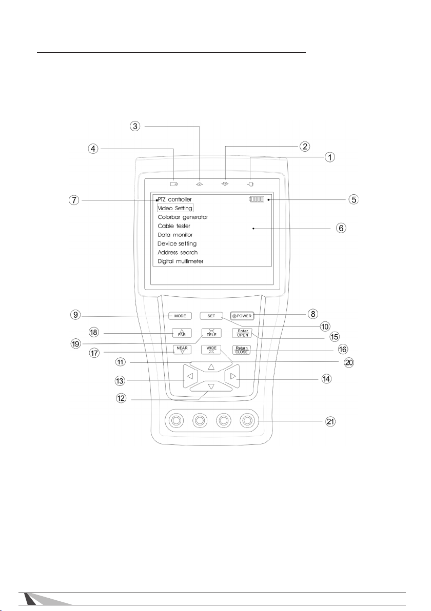
1. Power Indicator: Illuminates GREEN when tester is powered on.
2. Data-Reception Indicator: Illuminates RED while the data is being received.
3. Data-Transmission Indicator: Illuminates RED while the data is being
transmitted.
4. Charge Indicator: Illuminates RED while the battery is being charged. Once
the charging is complete, the indicator turns off automatically.
5. Battery Level Indicator: Displays the amount of battery charge remaining.
6. Main-menu: Displays main functions of WPS-CCTV-TESTER.
7. Sub-menu: Shows and sets the values of functions.
8. Power: Press & Hold for 2 seconds to turn tester On/Off; Press to turn PTZ
controller menu On/Off.
9. Mode: Displays the main-menu; Use the or keys to navigate to desired
menu item.
10. Set: Press to set parameters within certain sub menus.
11. Up: Scroll up to menu item or adjust parameter.
12. Left: Enter a sub-menu, or reduce the value of the parameter.
13. Right: Enter a sub-menu, or increase the value of the parameter.
14. Down: Scroll down to menu item or adjust parameter.
15. Enter/Open: Conrm the setting of parameters, or open the aperture.
16. Return/Close: Return or cancel while setting parameters, or close the
aperture.
17. Near: Focus the image IN.
18. Far: Focus the image OUT.
19. TELE: zoom in the image.
20. WIDE: zoom out the image.
21. Digital multi-meter connections.
© 2011 Wirepath Surveillance
7
Page 8
WPS-CCTV-TESTER Users Manual
2.2 Side Panels
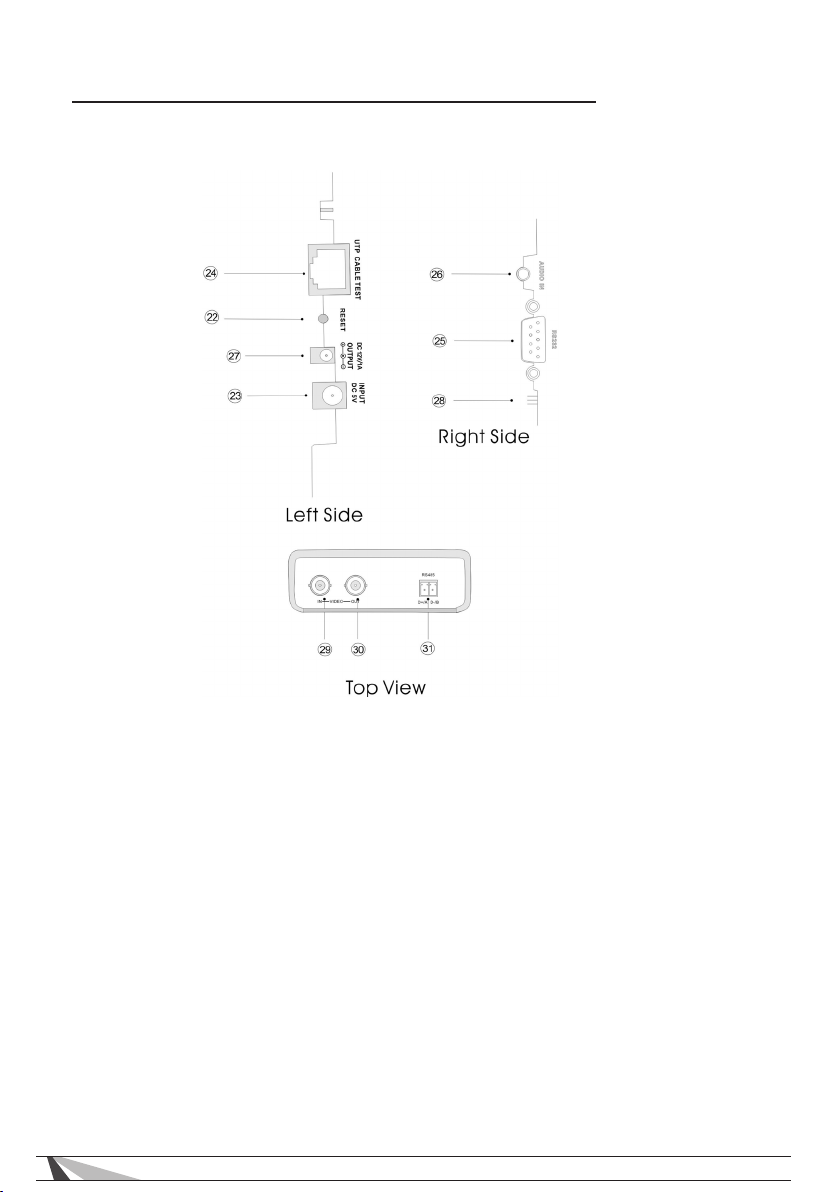
22. Reset all settings to default.
23. External power supply (5V DC): It is highly recommended to use the
supplied power adapter.
24. UTP cable port: use with supplied UTP Cat5e/6 cable tester.
25. RS232 interface: RS232 communication for the PTZ.
26. Audio input: 3.5mm stereo
27. 12V DC 1A power output: output 12V DC power for camera
28. Tester speaker
29. Video In: Composite BNC
30. Video Out: Composite BNC
31. RS485/422 Interface: RS485/RS422 communication for PTZ.
8
Page 9
WPS-CCTV-TESTER Users Manual
3 PREPARATION FOR USE
3.1 Installing the Battery
1. Remove the tester from the protective case
2. Remove the battery door located on the left side of the tester
3. Connect the battery cable to the socket located towards the top of the
tester
4. Install the door back onto the tester
5. Insert the tester into the protective case
3.2 Charging the Battery
Before using the tester for the rst time, fully charge the battery.
The Charge indicator will illuminate RED while the battery is charging; this
indicator will turn OFF once the battery is approximately 90% charged.
3.3 Power Button
Press & hold the power button for 2 seconds to turn the tester On or Off.
4 OPERATION
4.1 PTZ Controller
Display the input video images. Pan/tilt the P/T device and zoom in/ out the
image. Setup the controlling parameters such as protocol, communication
port, baud rate, PTZ ID, pan/tilt speed; set and call preset position.
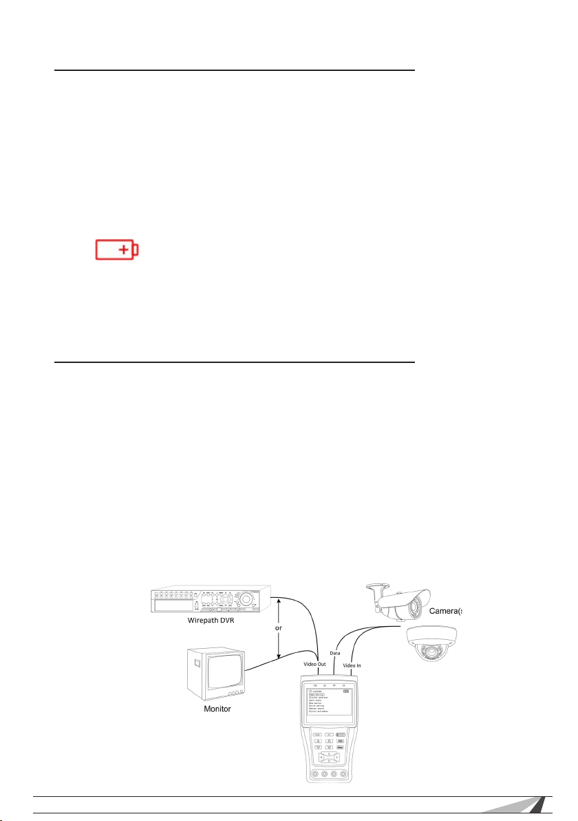
4.1.1 PTZ Connections
The following connections should be conrmed before use:
• Video In to the output of camera
• RS485 connector to the PTZ connection on the camera or controlling
device.
Note: RS485 connection accepts 6V max.
© 2011 Wirepath Surveillance
9
Page 10
WPS-CCTV-TESTER Users Manual
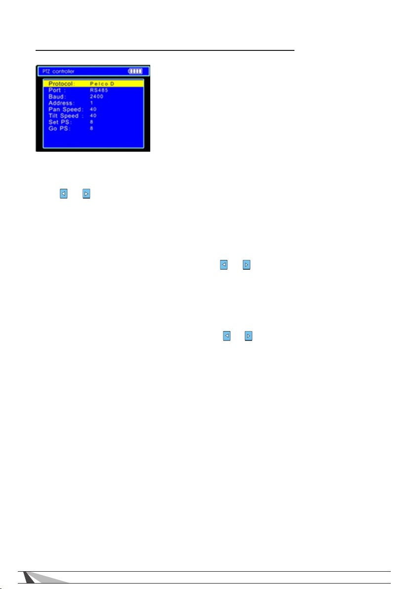
4.1.2 PTZ Settings
A. Protocol: Select the protocol according to the
protocol of the PTZ camera. 21 popular protocols
are available (Pelco D, etc).
B. Port: Select the communication port to control
the PTZ camera (RS232/422/485).
C. Baud: Select the baud rate according to baud
rate of the PTZ camera (150, 300, … , 19200bps).
D. Address: Set the ID according the ID of PTZ camera.
(0~254, BOSCHOSRD 1~16384).
Press or to adjust address, press TELE or WIDE for step 100 adjustments.
E. Pan Speed: Sets the pan speed of PTZ camera (0~63)
F. Tilt Speed: Sets the tilt speed of PTZ camera (0~63)
G. Set PS: Setup preset position (0~128)
1. Set the camera to desired PTZ position.
2. Press SET key to enter PTZ controller submenu
3. Navigate to SET PS and then press or key to select the preset
position number.
4. Press ENTER key to complete preset position setting or preset RETURN
key to display preset position setting.
H. Go PS: Call the preset position (0~128). The PTZ camera will go to the desired
preset position.
1. Navigate to GO PS and then press or key to select the preset
position number.
2. Press ENTER key to complete preset position selection or preset RETURN
key to cancel preset position selection.
10
Page 11
WPS-CCTV-TESTER Users Manual
4.1.3 Camera OSD
Accessing the OSD menu and preset of the PTZ camera may vary with control
systems (DVR, PTZ Controllers, etc.) from different manufacturers. Read the
manufacturer’s operation manual of the control system for details.
4.1.3.1 Wirepath Surveillance Cameras OSD
1. Navigate to PTZ CONTROLLER to enter PTZ controller mode.
2. Press SET to enter PTZ controller sub-menu.
3. Set PROTOCOL to match the setting of the camera
4. Set PORT to match the setting of the camera
5. Set BAUD to match the setting of the camera
6. Press SET to store the changes
7. Press ENTER to open the cameras OSD
4.1.3.2 PTZ OSD
1. Navigate to PTZ CONTROLLER to enter PTZ controller mode.
2. Press SET key to enter PTZ controller sub-menu.
3. Navigate to GO PS.
4. Press or key to select the preset number 64, and then press ENTER key to
display PTZ OSD menu.
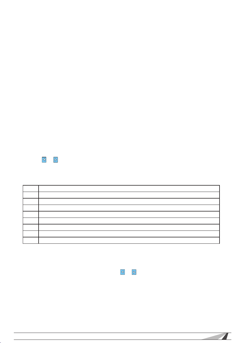
Preset PTZ Positions
Preset Action
33 Open Auto-ip function
34 Reset zero point of PTZ camera
64 Enter the main menu of the PTZ camera
95 Enter the main menu of the PTZ camera or stop the PATTERN recording.
96 Run pattern-1
97 Run preset tour-1
98 Run frame Scan
99 Run Auto scan
4.1.4 PTZ Continuing Scan Test
PTZ continuing rotate test is used to verify PTZ Rotation:
1. Press & Hold a direction button (e.g. or ). The camera will begin rotating.
2. Press the POWER button, then release. Camera will rotate continuously.
3. Press any direction key to stop the camera from rotating.
© 2011 Wirepath Surveillance
11
Page 12
WPS-CCTV-TESTER Users Manual
4.2 Video Setting
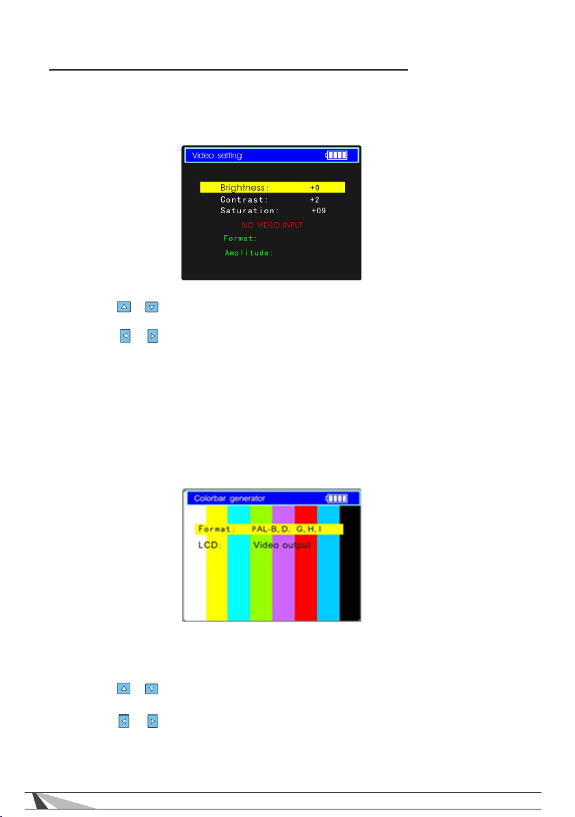
Customizes the brightness, contrast and saturation of the LCD Display
according to the environment. The signal from the connected camera is
analyzed to automatically set the display to the appropriate format (PAL/
NTSC).
1. Press the or key to select the desired setting.
2. Press the or key to change the value. Press ENTER to save the change or
press RETURN key to give up the change.
3. The Video Format and Video Level will be displayed in the lower portion of
the screen. If there is no video signal at the Video IN port of the WPS-CCTVTESTER, the type of NTSC or PAL , and Video Level will not be displayed.
4.3 Colorbar Generator
Outputs or receives different forms of video color bar to test monitor, video
cable or other equipment.
1. Press the or key to select the desired setting.
2. Press the or key to change the value.
3. Press ENTER key to save the change or press RETURN key to give up the
change.
12
Page 13
WPS-CCTV-TESTER Users Manual
4.4 UTP Cat5e/6 Cable Tester
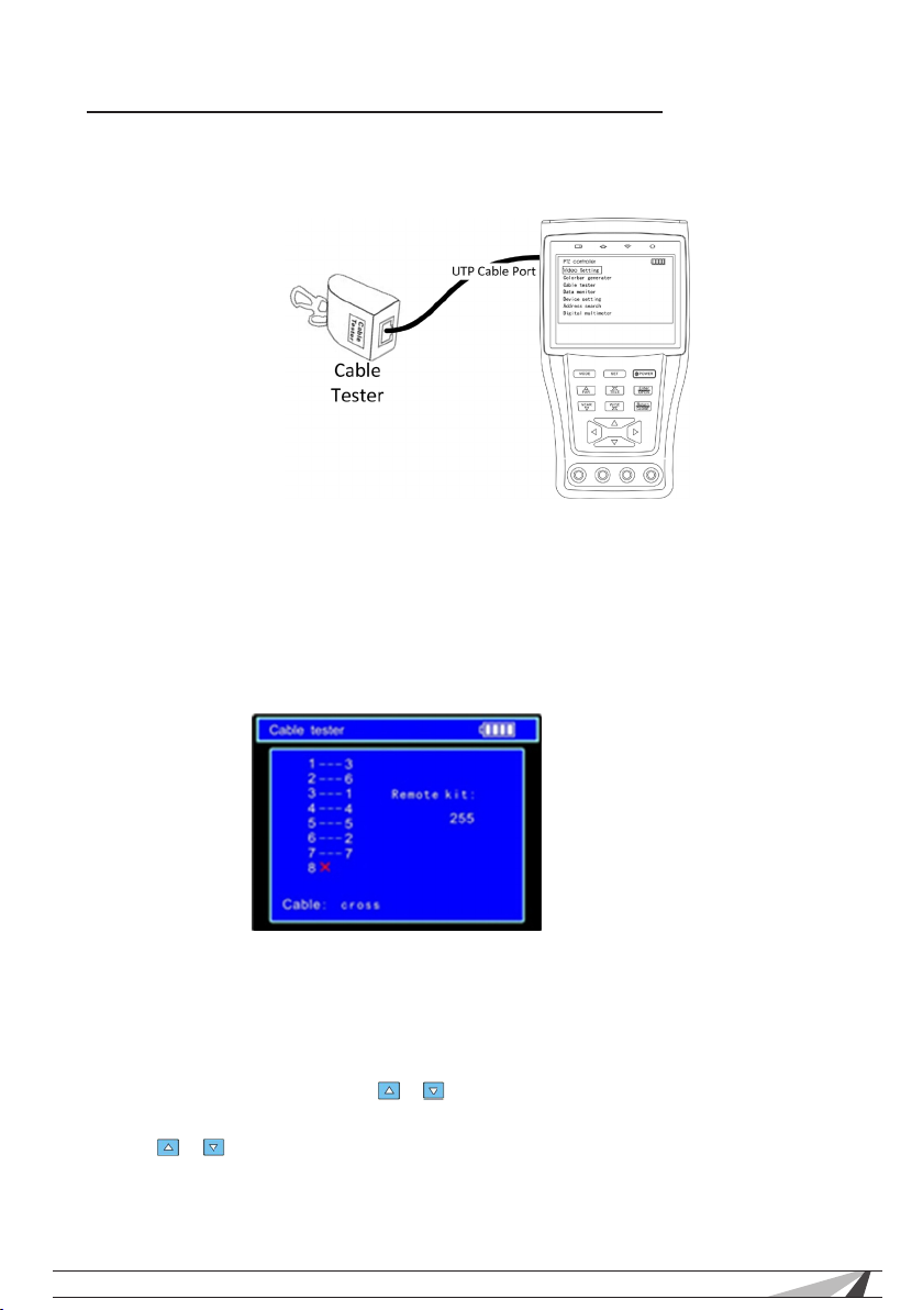
Tests UTP Cat5e/6 cable or telephone cable.
1. Connect Cat5e/6 cable or telephone cable with the WPS-CCTV-TESTER and
cable tester.
2. Select CABLE TESTER from the Main menu.
The status of the cable is displayed:
The left side shows the number of connectors (8) on the WPS-CCTV-TESTER.
The right shows the corresponding pins on the Cable Tester with the number of
the cable tester.
A red X indicates that the cable pin is open or shorted.
4.5 Data monitor
Displays the command data from RS232 or RS485 controlling system.
1. Connect the RS485 or RS232 interface of controlling system with the RS485 or
RS232 interface of the WPS-CCTV-TESTER (In case of RS485, A to A, B to B).
2. Press SET key and then press or key to select communication port
according to the system connection. Press SET key to save the change.
3. Press or key to select the baud rate according to the baud rate of
controlling system and then press SET key to save the change and capture
command data from controlling system.
4. Press RETURN key to clear the screen.
© 2011 Wirepath Surveillance
13
Page 14
WPS-CCTV-TESTER Users Manual
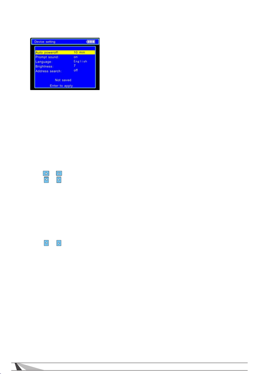
4.6 Device setting
Sets the parameters of the WPS-CCTV-TESTER
A. Auto Poweroff: Sets the amount of time for auto shut-down.
Disabled: Disables Auto Poweroff
Time for Auto Poweroff: 5 to 60 min in 5 min increments
B. Keypad tone: Enables of Disables keypad tone when key is pressed.
C. Language: Selects language of OSD menu
D. Brightness: Sets the brightness of OSD menu and background.
0 – Dim
7 - Bright
E. Address search: Enables or Disables PTZ Address Search menu.
Changing Settings
1. Press or key to select the desired setting.
2. Press or to change the value.
3. Press ENTER to save the change or press RETURN key to give up the change.
4.7 PTZ Address Scanning
Note: Isolate the PTZ camera with other PTZ cameras before searching. Other-
wise all the PTZ cameras in the same system will pan at the same time.
1. Press MODE to enter the Device Setting menu.
2. Press or to set ADDRESS SEARCH to ON. Press ENTER to conrm.
3. Press MODE to switch to the sub-menu.
(Note: The system returns to OFF after shutdown and the scan sub-menu closes
automatically.)
4. Press SET key to select protocol, communication port, and communication
rate the same as the PTZ camera.
5. Press NEAR or FAR key, the address values will constantly increase or
decrease.
NEAR: The tester will search continuously from 1 to 256. Once the camera pans
to the right, press any key to stop searching.
FAR: The tester will search continuously from 256 to 1. Once the camera pans
to the right, press any key to stop searching.
WIDE: The tester will search step by step from 1 to 256. When the ID is searched,
the PTZ camera will stop panning.
14
Page 15
WPS-CCTV-TESTER Users Manual
4.8 Digital Multi-meter
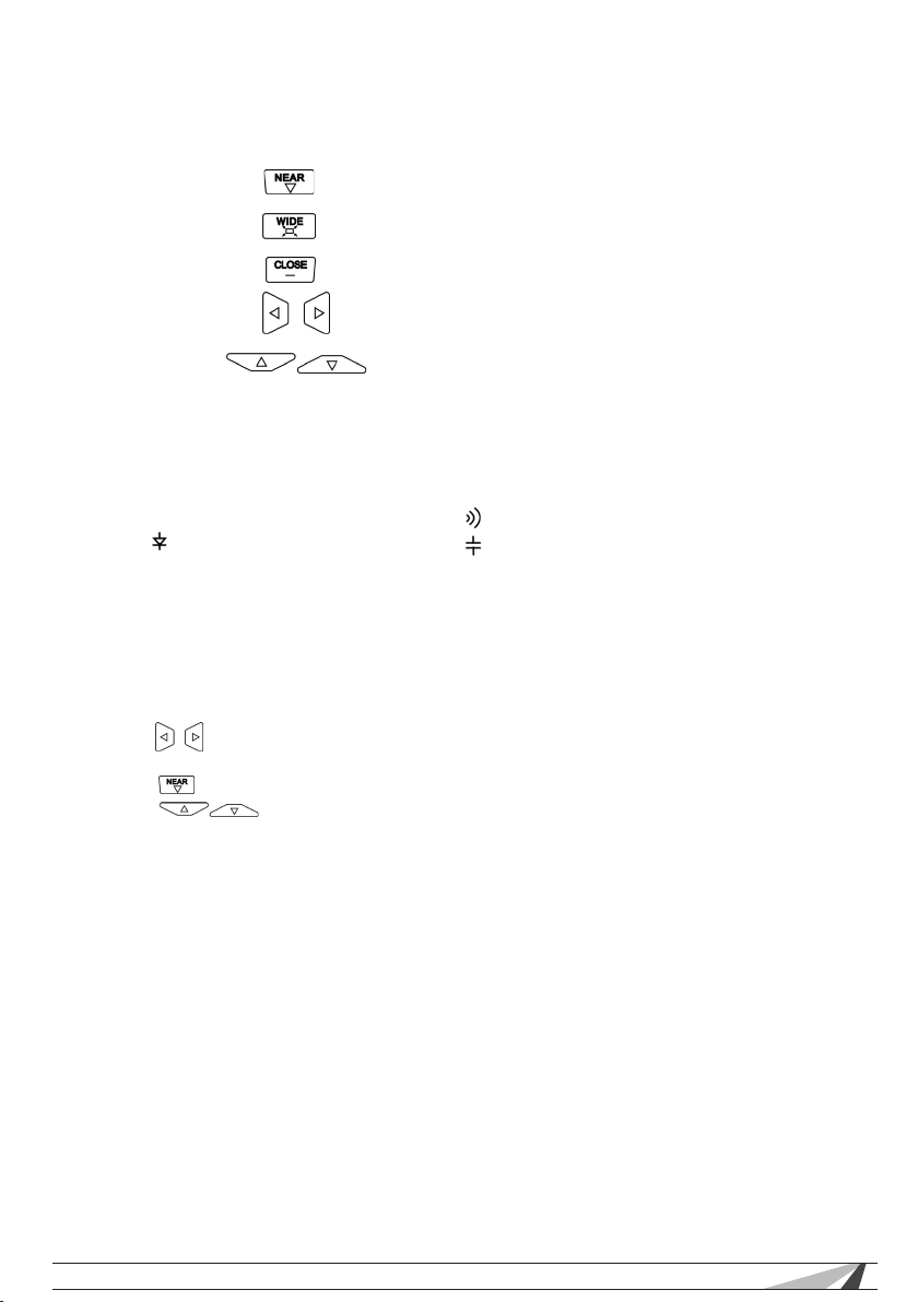
4.8.1 Multi-meter Functions
Auto range
Data Hold
Relative Measuring
Function Select
Manual Range
4.8.2 Multi-meter Symbols
U DC Voltage Measuring U~ AC Voltage Measuring
A DC Current Measuring A~ AC Current Measuring
Ω Resistance Measuring Continuity Testing
Diode Testing Capacitance Measuring
4.8.2.1 DC Voltage Measuring
WARNING: Do not input voltage higher than 660V DC. Voltages above 660V
DC can damage the tester.
1. Connect the black test lead to the COM jack and the red test lead to the V
jack.
2. Press to select U
3. Enter the desired range to measure
Press key to select Auto Range
Press to select the desired range manually
Available Range:
0.000V to 6.6V
00.00V → 66V
000.0V → 660V
000.0mV → 660mV
4. Connect test leads across the source or load under measurement.
5. The result is displayed on the LCD. The polarity of the red lead connection is
indicated along with the voltage value.
Note:
• When OL is displayed, it indicates over range situation and the higher range
should be selected.
• When the value scale to be measured is unknown beforehand, set the range
selector at the highest position.
© 2011 Wirepath Surveillance
15
Page 16

WPS-CCTV-TESTER Users Manual
4.8.3 AC Voltage Measuring
WARNING: Do not input voltage higher than 660V AC. Voltages above 660V
AC can damage the tester.
1. Connect the black test lead to the COM jack and the red test lead to the V
jack.
2. Press to select U~
3. Enter the desired range to measure
Press key to select Auto Range
Press to select the desired range manually
Available Range:
0.000V to 6.6V
00.00V → 66V
000.0V → 660V
000.0mV → 660mV
4. Connect test leads across the source or load under measurement.
5. The result is displayed on the LCD. The polarity of the red lead connection is
indicated along with the voltage value.
Note:
• When OL is displayed, it indicates over range situation and the higher range
should be selected.
• When the value scale to be measured is unknown beforehand, set the range
selector at the highest position.
4.8.4 DC Current Measuring
WARNING: Before connecting to the tester, power off the circuit to be tested.
1. Connect the black test lead to the COM jack and the red test lead to the
mA jack.
2. Press to select A
3. Enter the desired range to measure
Press key to select Auto Range
Press to select the desired range manually
Available Range:
0.000A to 6.6A
00.00A → 66A
000.0A → 660mA
000.0mA → 10A (connect to 10A Socket)
4. Connect test leads across the source or load under measurement.
5. The result is displayed on the LCD.
Note:
• When OL is displayed, it indicates over range situation and the higher range
should be selected.
• When the value scale to be measured is unknown beforehand, set the range
selector at the highest position.
• The maximum current of mA socket is 660mA, current over this value may
cause damage to the tester.
• The maximum current of 10A socket is 10A, current over this value may cause
damage to the tester.
16
Page 17

WPS-CCTV-TESTER Users Manual
4.8.5 AC Current Measuring
WARNING: Before connecting to the tester, power off the circuit to be tested.
1. Connect the black test lead to the COM jack and the red test lead to the
mA jack.
2. Press to select A~
3. Enter the desired range to measure
Press key to select Auto Range
Press to select the desired range manually
Available Range:
0.000V to 6.6mA
00.00V → 66mA
000.0V → 660mA
000.0mV → 10A (connect to 10A Socket)
4. Connect test leads across the source or load under measurement.
5. The result is displayed on the LCD.
Note:
• When OL is displayed, it indicates over range situation and the higher range
should be selected.
• When the value scale to be measured is unknown beforehand, set the range
selector at the highest position.
• The maximum current of mA socket is 660mA, current over this value may
cause damage to the tester.
• The maximum current of 10A socket is 10A, current over this value may cause
damage to the tester.
4.8.6 Resistance Measuring
WARNING: Before connecting to the tester, power off the circuit to be tested..
1. Connect the black test lead to the COM jack and the red test lead to the Ω
jack.
2. Press to select Ω
3. Enter the desired range to measure
Press key to select Auto Range
Press to select the desired range manually
Available Range:
0.000 Ω to 660 Ω
00.00 Ω to 6K Ω
000.0 Ω to 66K Ω
000.0 Ω to 660K Ω
000.0 Ω to 6M Ω
000.0 Ω to 66M Ω
4. Connect test leads across the source or load under measurement.
5. The result is displayed on the LCD.
Note:
• When OL is displayed, it indicates over range situation and the higher range
should be selected.
© 2011 Wirepath Surveillance
17
Page 18

WPS-CCTV-TESTER Users Manual
4.8.7 Continuity Testing
WARNING: Before connecting to the tester, power off the circuit to be tested.
1. Connect the black test lead to the COM jack and the red test lead to the
jack.
2. Press to select
3. Connect test leads across the source or load under measurement.
4. The result is displayed on the LCD.
Note:
• When OL is displayed, resistance is >660 Ω or the circuit is open.
4.8.8 Diode Testing
WARNING: Before connecting to the tester, power off the circuit to be tested.
1. Connect the black test lead to the COM jack and the red test lead to the Ω
jack.
2. Press to select
3. Connect test leads across the source or load under measurement.
4. If continuity exists (resistance <50 Ω), a tone will be heard from the built in
buzzer
5. The result is displayed on the LCD.
Note:
• Tester shows the approximate voltage drop of the diode.
• When OL is displayed, the connection to the diode is reversed.
4.8.9 Capacitance Measuring
WARNING: Before connecting to the tester, verify that the capacitor has been
fully discharged.
1. Connect the black test lead to the COM jack and the red test lead to
the jack.
2. Press to select
3. Enter the desired range to measure
Press key to select Auto Range
Press to select the desired range manually
Available Range:
0.000nF to 6.6nF
00.00nF to 66nF
000.0nF to 660nF
0.000uF to 6.6uF
00.00uF to 66uF
000.0uF to 660uF
0.000mF to 6.6mF
00.00mF to 66mF
4. Connect test leads across the source or load under measurement.
5. The result is displayed on the LCD.
18
Page 19
WPS-CCTV-TESTER Users Manual
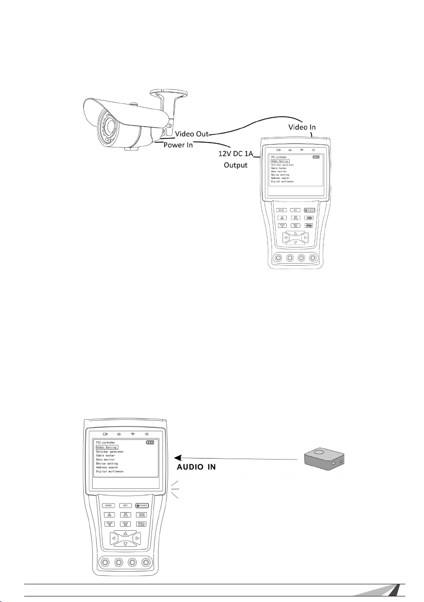
4.8.10 DC12V 1A Power Output
Power the camera with 12V DC 1A power output from the tester.
Note:
• Don’t connect the 12V DC 1A OUTPUT port to any connection outputting
voltage to avoid damaging the tester.
• Don’t connect the 12V DC 1A power to the power input port of the CCTV
tester to avoid damaging the tester.
• When the requirement of the camera is higher than 1A, the CCTV tester will
enter protection mode. Disconnect all the connections of the CCTV tester
and then connect the CCTV tester with power adaptor to resume testing.
4.8.11 Audio Input Test
Test the audio from DVRs, microphones, and other audio devices. Note: no
adjustments for input or output are provided in the tester.
© 2011 Wirepath Surveillance
19
Page 20
WPS-CCTV-TESTER Users Manual
5 SPECIFICATIONS
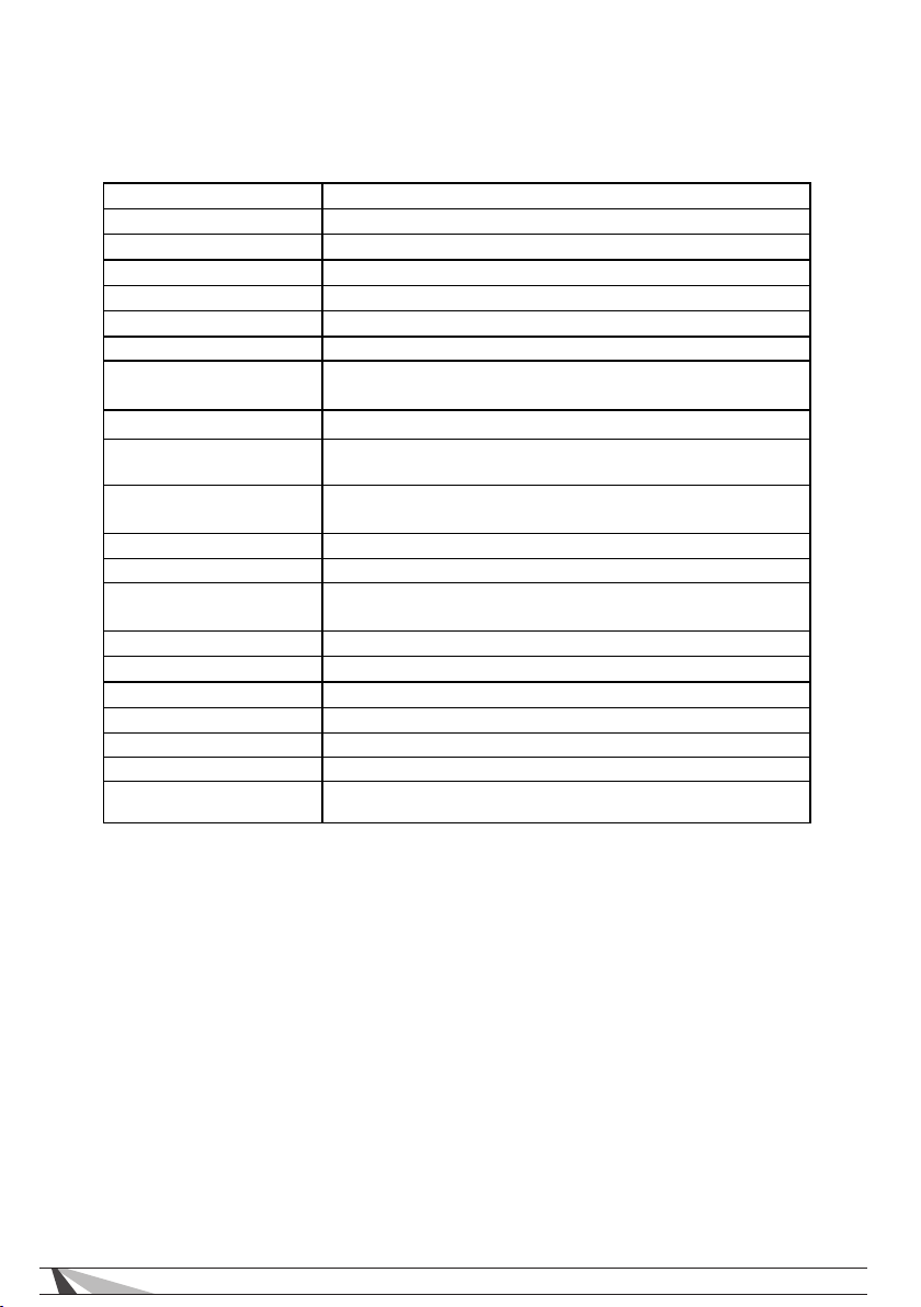
5.1 6.1 General Specications
Signalmode NTSC/PAL(Autosync)
Display 3.5inchColorTFT‐LCD(960x240resolution)
LCDadjustment Brightness,Contrast,Saturationadjustable
VideoIN/OUT 1channelBNCInput&1channelOutput
VideoOutputMode 1.0Vp‐p
Leveltest VideosignalsmeasuredinIREormV
Communication RS232,RS422simplexandRS485
PTZProtocol
BaudRate 150,300,600,1200,2400,4800,9600,19200bps
Colorbargeneration
Digital Multi-meter
UTPcabletest Yes
Audio input Yes
Data Monitor
Power Adapter 5VDC,2A
Battery Built‐in3.7VLithiumpolymerbattery,3000mAh
Rechargeable 4hourchargingtime,12houroperationtime
PowerOutput 12VDC1Apowerforcamera
Working Temperature 14°F~122°F
Working Humidity 30%‐90%
Dimension/Weight
Compatiblewithmorethan20protocolssuchasPELCO‐D/P,
Samsung,Panasonic,Lilin,etc.
OutputNTSC/PALcolorbarvideosignalsformonitortestingor
videocable.
Voltage,current,resistance,capacitancemeasuring,continuity
testing,diodetesting.
Capturesandanalyzesthecommanddatafromacontrolling
devicesuchasaDVRorPTZcontroller
6.93"x3.7"x1.42"
.75lb
20
Page 21
WPS-CCTV-TESTER Users Manual
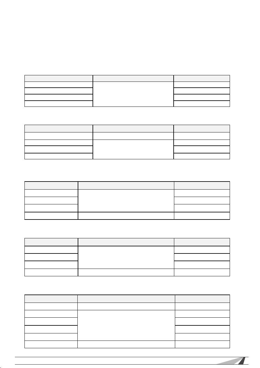
5 5.2 Multi-meter Specications
Counts: -6600~+6600
Conversion rate : 3 times/s
Current modes for clamp meter with ZERO function
DC Voltage
Range Accuracy Resolution
660mV (Manual range) ±0.3%+4 0.1mV
6.6V 1mV
66V 10mV
660V 100mV
AC Voltage
Range Accuracy Resolution
660mV (Manual range)
6.6V ±0.8%+6 1mV
66V 10mV
660V 100mV
±1.5%+6
0.1mV
DC Current
Range Accuracy Resolution
6.6mA ±0.5%+3 1uA
66mA 10uA
660mA 100uA
10A ±1%+5 10mA
AC Current
Range Accuracy Resolution
6.6mA ±0.5%+3 1uA
66mA 10uA
660mA 100uA
10A ±1%+5 10mA
Resistance
Range Accuracy Resolution
660Ω
6.6KΩ ±0.8%+2 1Ω
66KΩ 10Ω
660KΩ 100Ω
6.6MΩ 1KΩ
66MΩ ±1.2%+5 10KΩ
© 2011 Wirepath Surveillance
±0.8%+5
0.1Ω
21
Page 22
WPS-CCTV-TESTER Users Manual
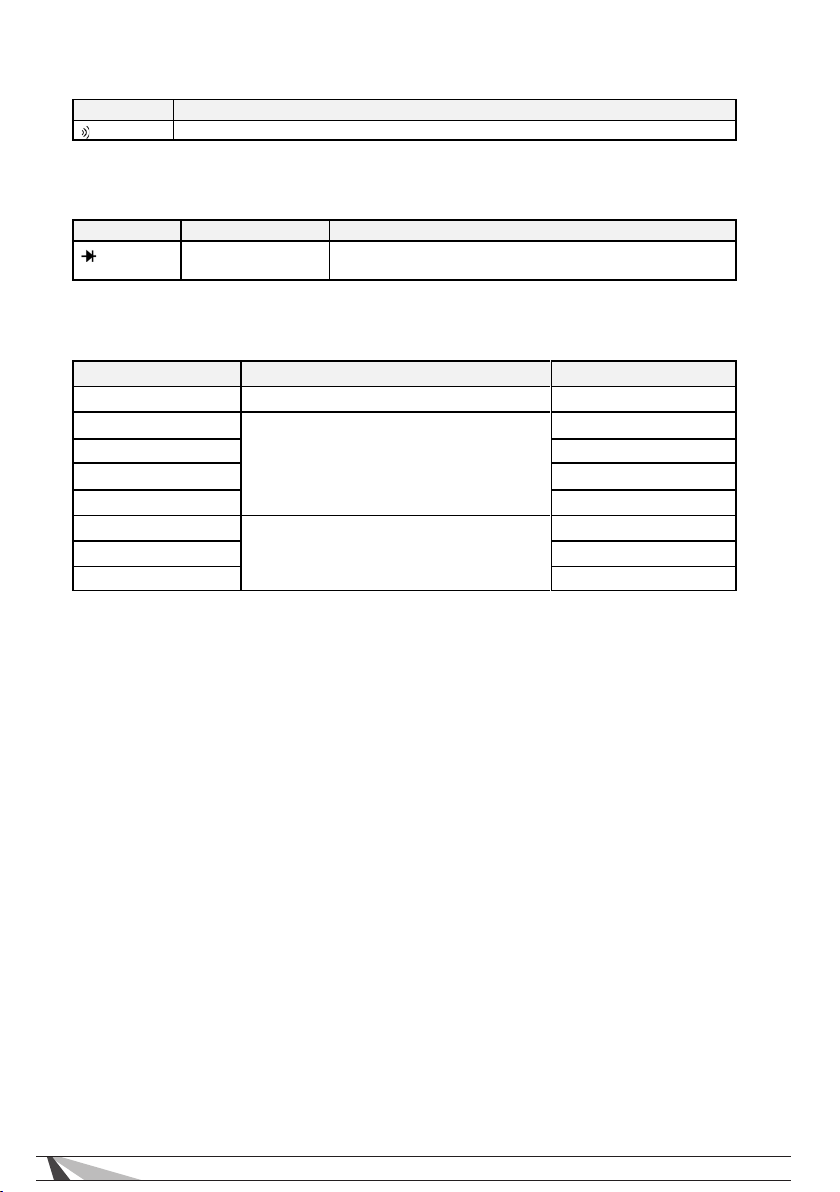
diode.
Continuity
Range Function
Built-in buzzer will sound, if resistance is lower than 50 Ω
Diode
Range Resolution Function
1mV Display: reads approximate forward voltage of
Capacitance
Range Accuracy Resolution
6.6nF
66nF ±3.5%+8 10pF
660nF 100pF
6.6µF 1nF
66µF 10nF
660µF ±5%+8 100nF
6.6mF 1µF
66mF 10µF
±0.5%+20
1pF
22
Page 23

WPS-CCTV-TESTER Users Manual
6 WARRANTY
Two-Year Limited Warranty
This Wirepath™ product has a 2-year Limited Warranty. This warranty includes
parts and labor repairs on all components found to be defective in material
or workmanship under normal conditions of use. This warranty shall not apply
to products which have been abused, modied or disassembled. Products to
be repaired under this warranty must be returned to SnapAV or a designated
service center with prior notication and an assigned return authorization
number (RA).
© 2011 Wirepath Surveillance
23
Page 24

111228
© 2011 Wirepath Surveillance
 Loading...