

Page 1
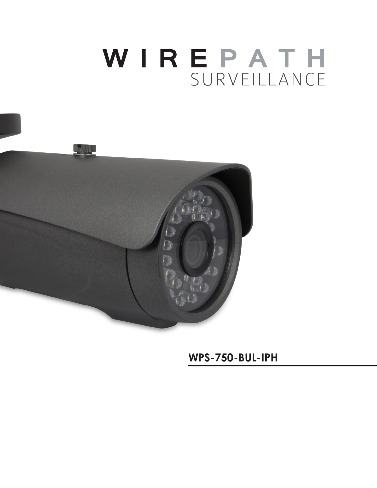
WPS-750-BUL-IPH
IP BULLET
CAMERA
INSTALLATION MANUAL
Review manual thoroughly before installation.
Retain for future reference.
Page 2
WPS-750-BUL-IPH Installation Manual
1. Safety Instructions
1. Read and follow all instructions and warnings in this manual. Keep for future reference.
2. Install according to manufacturer’s instructions.
3. Do not install near any heat sources such as radiators, heat registers, stoves or other apparatus (including ampliers)
that produce heat.
4. Only use attachments/accessories specied by the manufacturer.
5. Refer all servicing to qualied service personnel. Servicing is required when the apparatus has been damaged in any
way, such as when the power-supply cord or plug is damaged, does not operate normally, or has been dropped.
6. THE MAINS PLUG OF THE POWER SUPPLY CORD SHALL REMAIN READILY OPERABLE.
CAUTION
CAUTION: TO REDUCE THE RISK OF
The lightning ash with arrowhead symbol, within an equilateral triangle,
is intended to alert the user to the presence of uninsulated dangerous
voltage within the product’s enclosure that may be of sufcient magnitude to
constitute a risk of electric shock to persons.
ELECTRICAL SHOCK.
DO NOT REMOVE COVER. NO USER
SERVICEABLE PARTS INSIDE.
REFER SERVICING TO QUALIFIED
The exclamation point, within an equilateral triangle, is intended to alert the
user to the presence of important operating and maintenance (servicing)
instructions in the literature accompanying the appliance.
SERVICE PERSONNEL.
When viewing this document electronically, references to other sections are formatted to stand out. Click on a reference to navigate
to the section. Table of Contents entries may also be clicked to link to sections for faster navigation.
Example: (Cross-reference in one section to another part of the manual) For more information see section 2. Introduction.
Example: (Hyperlink to a website, will open in a new browser window) Go to www.SnapAV.com.
2
Page 3

WPS-750-BUL-IPH Installation Manual
Table of Contents
1. Safety Instructions 2
2. Introduction 7
2.1. Features 7
3. Package Contents 8
4. Required Items for Installation 8
5. How It Works 9
6. Camera Connections 10
6.1. Network Cable Recommendation (PoE and non-PoE) 11
6.2. Choosing the Right Network Equipment 11
6.3. PoE Requirements- IEEE 802.3af 11
7. Camera Installation Instructions 12
7.1. Wiring Installation 12
7.2. Prepare for Installation 12
7.3. Mount the Camera 12
7.3.1. Using Mounting Accessories 12
7.3.2. Surface Mounting 12
7.4. Connecting the Test Adapter 12
7.5. Aiming the Camera 12
7.6. Focus, Zoom, and Position 13
7.7. Closing the Camera 13
7.8. Network Software Setup - IP Installer 14
7.8.1. Running the IP Installer 14
7.9. IP Installer-Conguring Camera IP Settings 15
7.10. Verify Access through the Main Camera Interface 15
8. IP Camera Web Interface - Setup and Use 16
8.1. First Time Access Instructions 16
8.1.1. Recommendations for Best Web Viewing Performance 16
8.2. Camera Web Browser Interface 17
8.2.1. Web Interface Layout - Top Bar 17
8.2.2. Web Interface Layout - Bottom Bar 18
© 2014 Wirepath Surveillance
3
Page 4

WPS-750-BUL-IPH Installation Manual
9. Camera Conguration Menu Setup 19
9.1. Conguration Menu - Access and Navigation 19
9.1.1. Accessing the Menu 19
9.1.2. Conguration Menu Layout 19
9.1.3. Conguration Menu Guidelines 19
9.2. System Information and Settings 20
9.2.1. System Information Menu Settings 20
9.2.1.1. Server Information 20
9.2.1.2. OSD Setting 20
9.2.1.3. Time Setting 21
9.2.1.4. Network LED 21
9.2.2. Camera Time Setup 22
9.2.2.1. NTP Time 22
9.2.2.2. Synchronize with PC’s Time 22
9.2.2.3. Manual 22
9.2.2.4. Internal Clock 22
9.2.2.5. NTP Setup Instructions (For Cameras with Internet Access) 23
9.2.2.6. Time Setup for Cameras without Internet Access 23
9.2.3. User Management 24
9.2.3.1. Anonymous User Login 24
9.2.3.2. Add User (Guest Account only) 24
9.2.3.3. User List 24
9.2.3.4. User Account Levels 24
9.2.3.5. Administrator Account Setup 25
9.2.3.6. Add, Edit, or Remove a Guest Account 25
9.2.4. System Update 26
9.2.4.1. Firmware Upgrade 26
9.2.4.2. Reboot System 26
9.2.4.3. Setting Management 26
9.2.4.4. How to Back up Camera Settings 27
9.2.4.5. Load Backup Settings to the Camera 27
9.2.4.6. Upgrade the Firmware 28
9.3. Network IP Settings 29
9.3.1. Basic IP Settings 29
9.3.1.1. IP Assignment 29
9.3.1.2. Port Assignment 30
9.3.1.3. UPnP 30
9.3.1.4. RTSP Setting 31
9.3.1.5. Multicast Setting (Based on RTSP Server) 31
9.3.1.6. ONVIF 32
9.3.1.7. Bonjour 32
9.3.1.8. Link Layer Topological Discovery (LLTD) 32
9.3.2. Advanced IP Settings - HTTPS Access Setup 33
9.3.2.1. Created Request 33
9.3.2.2. Installed Certicate 33
4
Page 5

WPS-750-BUL-IPH Installation Manual
9.3.2.3. Connection Types 33
9.3.3. Advanced IP Settings - SNMP 34
9.3.4. Advanced IP Settings - Access List (IP Filter) 35
9.3.4.1. IP Address Filter Setting 35
9.3.4.2. Add or Remove IP Addresses or Ranges 36
9.3.4.3. Controlling Administrator Access 36
9.3.5. Advanced IP Settings - QoS/DSCP 37
9.3.5.1. QoS / DSCP Setting 37
9.3.6. PPPoE Setup 38
9.3.6.1. PPPoE Overview 38
9.3.6.2. PPPoE Settings 38
9.3.6.3. Send Mail after PPoE Dialed 38
9.3.7. DDNS Setup 39
9.3.7.1. DDNS Overview 39
9.3.7.2. DDNS Settings 39
9.3.7.3. State (DDNS) 39
9.3.7.4. Setting Up a DDNS Address – WirepathDNS 40
9.3.8. Server Settings 41
9.3.8.1. Email Notications 41
9.3.8.2. Mail Settings 41
9.3.8.3. FTP Settings 42
9.3.8.4. Network Share Settings 43
9.4. Camera A/V Settings 44
9.4.1. Image Settings Menu 44
9.4.1.1. Tips for Getting the Best Camera Image 45
9.4.2. How to Congure Day & Night Settings (Color Modes) 46
9.4.2.1. Day & Night Modes 46
9.4.2.2. Day & Night Modes 47
9.4.2.3. Light Sensor Mode (Default Mode) 47
9.4.2.4. Day & Night Times Mode 47
9.4.2.5. How to Congure Privacy Masks 48
9.4.3. Video Settings Menu Overview 49
9.4.3.1. Video Setting (For BNC Test Adapter Output) 49
9.4.3.2. Streaming 1 and 2 Setting 49
9.4.3.3. Streaming 3 (JPG/MJPEG) 49
9.4.3.4. Streaming 4 (3GPP) 49
9.4.4. Video Streaming 1 and 2 Setup 50
9.4.5. Streaming 3 and 4 Setup 52
9.4.5.1. Streaming 3 52
9.4.5.2. Streaming 4 52
9.4.6. Audio Settings 53
9.4.7. Camera Audio Technology Overview 54
9.5. Event Record Setup and Scheduling 55
9.5.1. Event Settings Menu 55
9.5.1.1. Record File 56
© 2014 Wirepath Surveillance
5
Page 6

WPS-750-BUL-IPH Installation Manual
9.5.1.2. Record Time Setting 56
9.5.1.3. Network Disconnected 56
9.5.1.4. Network IP Check 56
9.5.2. Conguring Motion Detection Areas 57
9.5.2.1. Motion Detection Settings Overview 57
9.5.2.2. Adding a New Motion Detection Area 58
9.5.2.3. Removing a Motion Detection Area 58
9.5.3. Schedule Menu 59
9.5.3.1. Snapshot Menu 59
9.5.3.2. How to Set Up Scheduling for Events 60
9.5.3.3. Set up Snapshot 60
9.5.4. I/O Settings 61
9.5.4.1. Input Settings 61
9.5.4.2. Output Settings 61
9.6. Log List 62
9.6.4.1. Motion Detection Log 62
9.6.4.2. All Logs 62
9.7. SD Card Menu 63
9.7.1. Playback 63
9.7.2. SD Management 63
10. Internal Heater Overview 64
10.1. Safe Operating Range 64
11. Reset Procedure 65
12. Mobile App Access 65
13. Specications 66
14. Dimensions 68
15. Warranty 69
16. Contacting Technical Support 69
6
Page 7

WPS-750-BUL-IPH Installation Manual
2. Introduction
Thank you for purchasing a Wirepath™ IP Surveillance camera. The WPS-750-BUL-IPH is an indoor/outdoor camera designed for
mounting to any wall, ceiling or surface, for easy monitoring over a web or smartphone interface.
We recommend that this document be read in its entirety before proceeding with system design, installation, or operation of the
camera.
2.1. Features
• 1/2.7" 2MP CMOS Sensor
Advanced CMOS sensor provides improved picture quality over a typical CCD sensor. Supports full Full 1080p HD
(1920x1080) at 30FPS.
• Varifocal Lens
This camera features a varifocal lens with a focal length of 2.8-12 mm.
• H.264/ MJPEG Quadruple Stream Optimization
Supports up to 4 simultaneous streams of compression typically used for the following situations:
• High Res stream optimized for NVR Record or Local Network viewing
• Lower Res stream optimized for Remote viewing
• Lower Res stream optimized for Control Systems (same res as Stream 2)
• Low Res stream for Mobile Viewing
• Low Temperature Operation
A heater is included that automatically turns on and off to ensure the camera operates within an optimum temperature range,
and helps to minimize condensation inside the housing at low temperatures. The heater activates automatically at 50°F and
deactivates at 60°F.
• IR up to 65 ft
• True Day/Night (IR Cut Filter)
For more accurate, vivid color reproduction during daytime use, an IR Cut lter is automatically moved over the lens to block
unwanted IR. At night, the lter is removed to deliver maximum visibility and clear IR illumination.
• Advanced Image Processing
Advanced DSP (Digital Signal Processor) to improve image quality including:
• Sense Up: Automatically slows the shutter speed to improve image quality in low light.
• D-WDR (Digital Wide Dynamic Range): Provides clearer images and even lighting in applications that are
simultaneously bright and dark. This is particularly useful in areas with windows and lots of natural light.
• 2D and 3D Digital Noise Reduction (DNR): Intelligently scans the image and reduces noise in low-lux conditions for a
cleaner, crisper image.
• Privacy Mask
Block out sensitive or privileged areas by placing rectangular blocks or “masks” over up to three installer-dened areas.
• Power Over Ethernet (PoE IEEE 802.3af)
Camera can be powered by PoE using the same Cat5e/Cat6 cable that connects to the network. No need to pull a 2nd power
cable to the location. Compatible with all PoE network switches that support PoE IEEE 802.3af and PoE power injectors.
• Edge Storage
The camera supports microSD cards (up to 32GB, card NOT included). Images, short recordings and logs can be stored on a
microSD installed into the camera. This is useful as a backup if the network connection to the NVR is lost.
• Test Port for Quick Setup during Install
• Analog Video Out
• Local 12V DC Power for Camera
• IP-66 Weatherproof Rating
With an IP-66 rating, this camera is protected from dust and water, making it effective for indoor and outdoor installations.
• ONVIF
© 2014 Wirepath Surveillance
7
Page 8

WPS-750-BUL-IPH Installation Manual
3. Package Contents
• (1) WPS-750-BUL-IPH Camera
• (1) WPS-ACC-PWR Power Adapter
• (1) BNC Test Adapter
• (1) Female to Female RJ45 Adapter
• (1) 3mm Allen Key
NOTE: A POWER SUPPLY IS NOT INCLUDED WITH THIS CAMERA. The PS-12DC-1A, WPS-PS multiple output power supply
or a Power over Ethernet (PoE) switch is recommended.
• (4) Screws
• (4) Wall Fasteners
• (1) Spare Silica Pack
• (1) Quick Start Guide
4. Required Items for Installation
The following items are required during the installation of a Wirepath™ IP camera. Prepare all parts and tools in advance to ensure
that the installation can be performed smoothly.
• Local Ethernet network installed
• All cameras to be installed in the system
• PoE Ethernet equipment or power supplies and wiring to power cameras
• Network connection at each camera location
• Access to a PC connected to the local network
• Static IP address to assign to the camera
• Additional access information for network equipment:
• Router / Switch Details – Contact the network admin to obtain access to equipment settings
• Admin Rights – Required to setup the network and port forwarding for remote access
• Default Gateway
• Subnet Mask
• DNS Address
• Recommended for mounting cameras and wiring:
• Hand tools
• Drill (may be needed for mounting the camera)
• Extra connectors for terminating cables on the job
8
Page 9
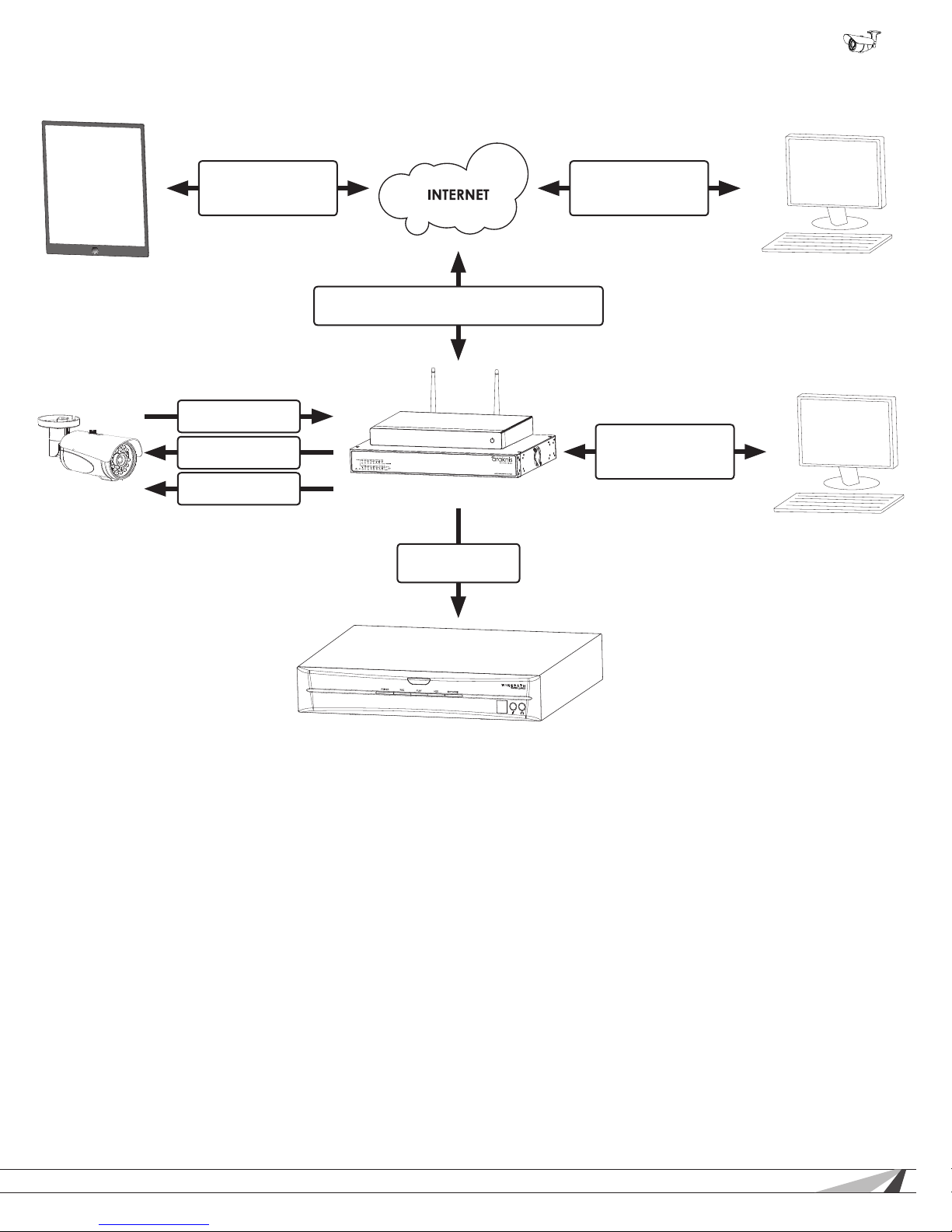
5. How It Works
WPS-750-BUL-IPH Installation Manual
Smartphone/Tablet
IP Camera
WPS-IP Mobile App
Streaming
Streaming audio/
video
Access from IP
interface
Power from PoE or
power supply
Browser Interface
Streaming & setup
Web-Based Computer
Port Forwarding and DDNS allows camera to be
accessed from the Internet
Browser Interface
Streaming, Setup
Gigabit router and switch
LAN-Based Computer
Video streams to
NVR for recording
Wirepath™ NVR
How Does IP Video Surveillance Work?
Wirepath™ IP cameras use a digital image processor to capture video in a stream of packets that are broadcast using a standard
Ethernet network. These packets can be received by several devices at once, including local PCs, mobile devices, and recorders
(NVRs) on the same network, or even off the network (with the correct setup and web access).
Users can see the camera feed through the interface of their choice, or see recorded footage from a storage device like an NVR.
Wirepath Surveillance offers apps for iOS® devices, Android® smartphones, Windows PC, and Mac computers. Drivers for various
popular control systems are also available for integration with a control system.
Access and Use
For local network (LAN) access, a static IP address is assigned to the camera in the network router. The user enters this address
into a PC, smartphone, or other device connected to the LAN, and logs in using a customizable username and password.
For access outside the LAN, a port is forwarded to the camera in the network router settings and a DDNS address is set up in the
camera. This enables the same streams from the camera to be broadcast anywhere in the world over an Internet connection.
In systems where the camera stream must be recorded, a network video recorder (NVR) is connected to the LAN. The address and
login credentials for the camera are entered and the stream can be captured as needed for later viewing.
© 2014 Wirepath Surveillance
9
Page 10
WPS-750-BUL-IPH Installation Manual
6. Camera Connections
Wirepath™ Surveillance IP Cameras can be powered by Power over Ethernet (PoE) through the Cat5e/Cat6 Ethernet connection.
This method is recommended because it limits the amount of wiring required, reducing installation cost and time. The camera must
be connected to a compatible PoE-equipped router/switch or a PoE injector for this method to work.
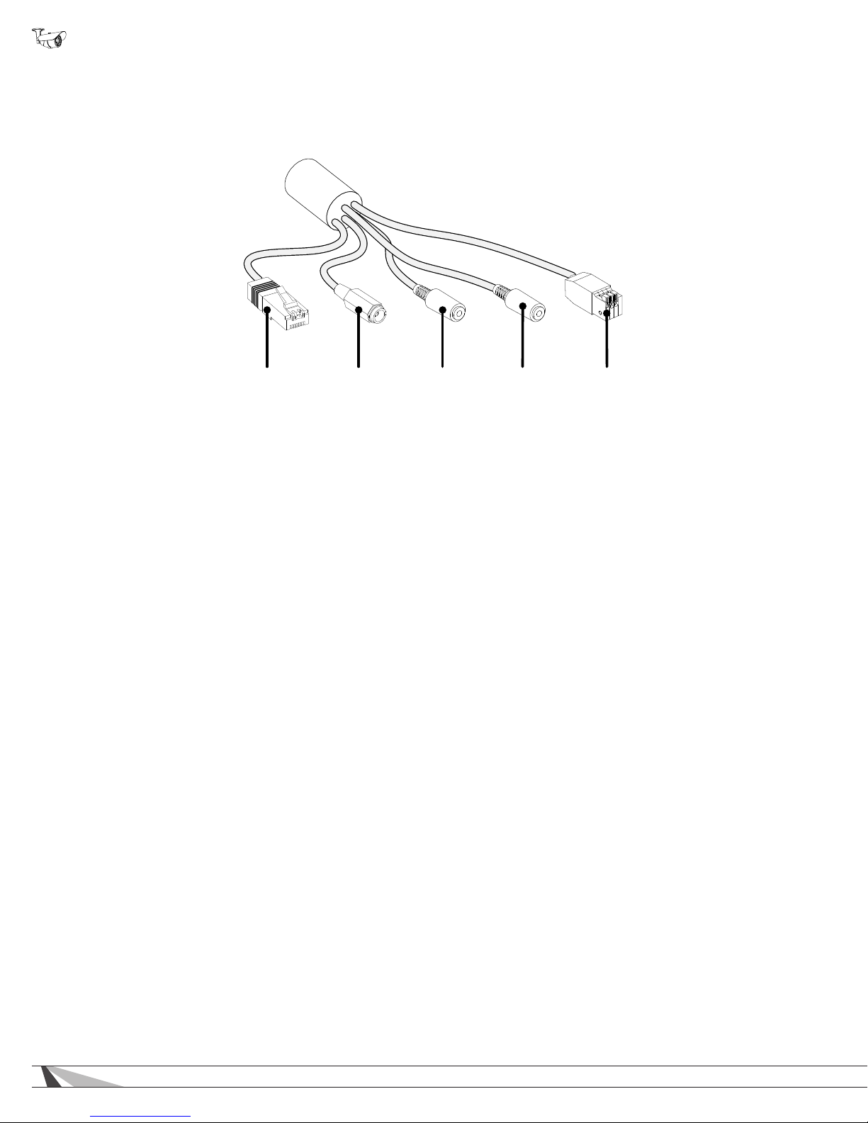
)
5. Contact
& Relay
1. Ethernet
2. 12V DC In
(Black)
3. Audio In
(Pink)
. Audio Out
4
(Green
7. Ethernet Connection (RJ45)
Connect to network switch for communication to and from the camera. Pin out follows EIA standard 568-B.
8. 12V DC Power In (Barrel Connector)
Connect to a 12V DC power supply. The camera is not supplied with a power supply. No power supply is needed if PoE is
being used to power the camera via the Ethernet connection.
Warning! Use only a 12V DC power supply with this camera. Higher voltages or AC current will cause permanent damage
that is not covered by the warranty.
9. Audio In (1/8" / 3.5mm Stereo)
Connect a microphone to receive audio at the cameras location.
10. Audio Out (1/8" / 3.5mm Stereo)
Connect to an amplier and speakers to allow for communication between the viewer and the cameras location.
11. Contact & Relay (Spring Loaded Terminal)
Connect to devices with contact closure output to trigger recording, or activate devices like lights or sirens at the camera
location.
10
Page 11

WPS-750-BUL-IPH Installation Manual
Pin 1 White/Orange Pin 5 White/Blue
Pin 2 Orange Pin 6 Green
Pin 3 White/Green Pin 7 White/Brown
Pin 4 Blue Pin 8 Brown
6.1. Network Cable Recommendation (PoE and non-PoE)
• Cable Type: Cat5e/6
• Max Length: 100 meters (328 feet)
• Termination: 568B recommended
TIA/EIA Standard 568-B (Gold Pins Facing Up)
6.2. Choosing the Right Network Equipment
Streaming content from IP Cameras requires more bandwidth than most IP devices. We recommend using 1Gbps routers and
switches to maintain a high quality streaming image. To reduce trafc on the overall network, we also recommend that all IP
Surveillance devices be connected to a dedicated 1Gbps switch or VLAN.
6.3. PoE Requirements- IEEE 802.3af
Cameras must be connected to a PoE injector (inline PoE power supply) or a PoE-equipped port of a network router or switch built
to IEEE 802.3af standards. Consider installing a dedicated PoE switch specically for IP cameras on the network to avoid issues
relating to power shortage.
• Minimum requirement for PoE ports:
• Voltage: 44V DC
• Wattage: 15.4W
• Amperage: 350mA
© 2014 Wirepath Surveillance
11
Page 12
WPS-750-BUL-IPH Installation Manual
A
B
C
7. Camera Installation Instructions
7.1. Wiring Installation
A. Run a Cat5e/6 cable from the network port to the camera location and terminate
both ends to 568B.
B. (Non-PoE applications only) Run wiring to the camera from the power supply
location. Use the voltage drop calculator at www.SnapAV.com to determine the
wire size needed.
C. (Non-PoE applications only) Connect the power supply to the wire at the head end
using electrical connectors (not included), and attach the WPS-ACC-PWR-M to
the wire at the camera location. Be sure to use the correct polarity.
D. (Non-PoE applications only) Connect the power supply to a suitable outlet and
test the voltage at the camera side of the wire using a volt meter. Disconnect the
power supply from the outlet until camera installation is otherwise complete.
7.2. Prepare for Installation
A. Unpack the camera and locate the included hardware, silica packet, and 3mm
Allen wrench.
B. Depending on the mounting location, it may be easier to position the correct eld-
of-view before installation. See step 7.4 “Aiming the Camera” below for adjustment
instructions.
7.3. Mount the Camera
7.3.1. Using Mounting Accessories
A. Mount the accessory according to its instructions.
B. Make wiring connections, and mount the camera.
C. Continue these instructions at 7.4 “Aiming the Camera” below to complete camera
installation.
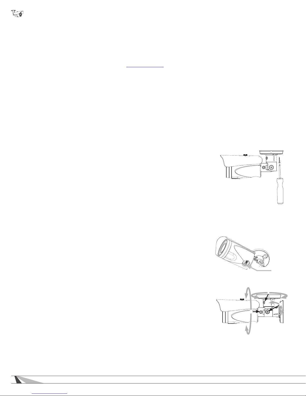
7.3.2. Surface Mounting
A. Use the camera mounting base as a template to mark the location of the 3 screws
on the mounting surface.
B. Connect the camera to the wiring and move it into position. Avoid pinching the
wires between the camera and the mounting surface.
C. Use 3 of the included screws to secure the camera and hand-tighten them evenly.
7.4. Connecting the Test Adapter
A. Connect the BNC Test Adapter.
B. Connect a test monitor to the camera’s test adapter BNC and power tails. Set the
camera’s eld-of-view as desired.
C. Connect a power supply to the secondary power connection on the camera (if
main power connection is not active).
7.5. Aiming the Camera
A. Use the 3mm Allen wrench to loosen and tighten each adjustment screw:
• Horizontal rotation (A)
• Swivel left or right (B)
• Tilt viewing angle (C)
Test Adapter
Connector
12
Page 13
WPS-750-BUL-IPH Installation Manual
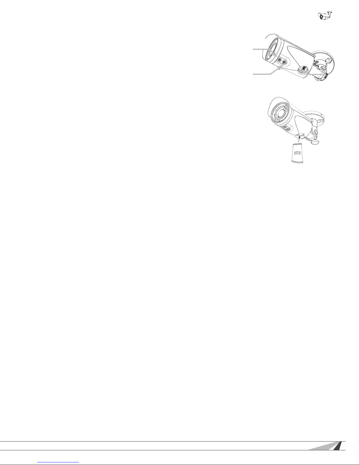
7.6. Focus, Zoom, and Position
A. The lens of the camera has manual focus and zooms knobs for setting the correct
eld-of-view.
B. Connect the test adapter from the camera to a monitor as shown below for viewing
adjustments.
C. Use the included 3mm Allen key to adjust focus and zoom.
D. Disconnect the WPS-CCTV-TESTER or monitor and power supply from the local
test connections and disconnect the BNC Test Adapter once the ideal scene is set.
7.7. Closing the Camera
Recommendation: Before replacing the cap we recommend that a new silica gel pack
be inserted into the camera to ensure that any moisture present will be removed.
A. Install a microSD card in the slot if desired.
B. Remove the spare silica packet from its sealed foil package (taking care not to rip
the inner packet) and place it inside the test adapter opening.
C. Close the cap, and make sure the cap is sealed securely.
Focus
(Front)
Zoom
(Rear)
Test Adapter
Connector
© 2014 Wirepath Surveillance
13
Page 14
WPS-750-BUL-IPH Installation Manual
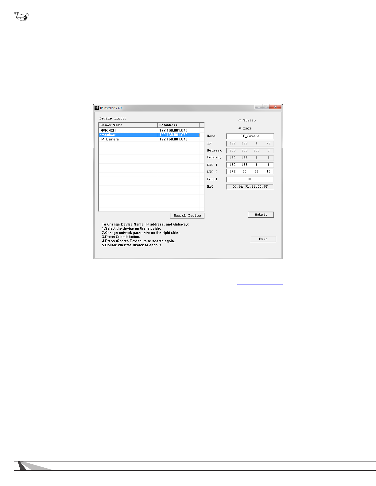
7.8. Network Software Setup - IP Installer
The IP Installer software included with the camera provides a quick view of Wirepath™ IP Surveillance devices connected to the
local network. Use the Installer to search for and set basic IP settings for each camera.
Before starting any conguration or service of Wirepath™ IP devices, we recommend checking for a newer version of the IP
Installer on the camera’s support tab at www.SnapAV.com.
Important! Active VPN connections anywhere on the network will prevent the IP Installer from working correctly. Close all
VPN connections before running the Installer.
Device List displays
connected devices on
the network.
Click a device name to
make changes in the
right column.
Double-click a device
name to load the IP
interface using your web
browser.
Right column shows
current IP settings for
the highlighted device.
Change settings by
updating the elds and
Click Search Device to
refresh the Device List.
then clicking “Submit”.
7.8.1. Running the IP Installer
A. The IP Installer EXE le can be downloaded from the camera’s support tab at www.SnapAV.com. No installation is required for
use. Extract the le from the ZIP le (if compressed) and move it to the Desktop or folder of your choice.
B. Run the software. Windows may attempt to block the action. If this occurs, allow the software to run. No changes will be made
to Windows or other system les. It may be necessary to log in as or provide the administrator account password for the PC for
the IP Installer to run.
C. When it opens, the installer automatically scans the network for any connected Wirepath™ IP Cameras, NVRs, and Encoders.
Click “Search Devices” to rescan the network if more devices are added and make changes to camera settings as needed.
D. Click the “X” at the top right corner or the “Exit” button to close the IP installer when all devices are congured. Windows may
display an error that the software did not install correctly when it closes but this should be disregarded.
14
Page 15
WPS-750-BUL-IPH Installation Manual
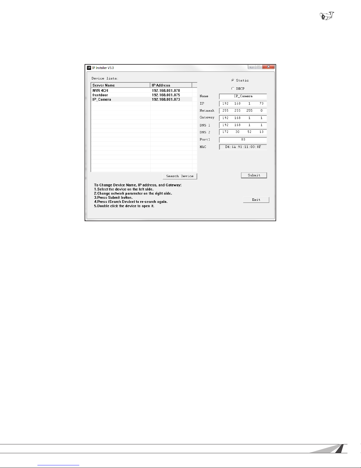
7.9. IP Installer-Conguring Camera IP Settings
By default, the camera will receive a DHCP IP address. This should be changed to a reserved or static IP address so that the
camera remains accessible after setup. Obtain the settings below from the network administrator before installation.
Consult with the router manufacturer for instructions to correctly set up a reserved or static IP address.
A. Open the IP Installer and single-click on a camera in the Device List. Its current settings will appear in the right column elds.
B. Select “Static” at the top of the right column. Network settings may now be modied.
C. Assign a name to the camera based on the scene or location (limited to 31 characters) Examples: FrontDoor1, SideDoor...
D. Enter the reserved static IP address for the camera.
E. Enter the Net Mask (usually 255.255.255.0).
F. Enter the default Gateway (found in the router).
G. Enter the DNS 1 address (found in the router).
H. Enter the DNS 2 address (found in the router). Set DNS 2 “0.0.0.0” if no DNS 2 is set in the router.
I. Enter a unique port number to enable remote Internet access to the camera. Use port numbering that is consistent and easy to
remember. We recommend using 4 digits, “8” followed by the last three numbers of the camera’s IP address.
Examples:
Camera IP Address Port
Patio 192.168.1.050 8050
Front Door 192.168.1.100 8051
7.10. Verify Access through the Main Camera Interface
Once the IP address has been set, the camera can be accessed through the web browser. Note that on initial access to each
camera, Active X controls will need to be installed on each PC that is used to access the camera. Continue to the next section for
web browser access and setup.
© 2014 Wirepath Surveillance
15
Page 16
WPS-750-BUL-IPH Installation Manual
8. IP Camera Web Interface - Setup and Use
8.1. First Time Access Instructions
A. Connect the PC to the same local network (LAN) the camera is connected to.
B. Open the web browser and enter the IP address that was assigned to the camera. The address should include the port number
assigned to the camera if one was set. See the example:
• IP Address using default port: http://192.168.1.015
• IP Address using port 8015: http://192.168.1.015:8015
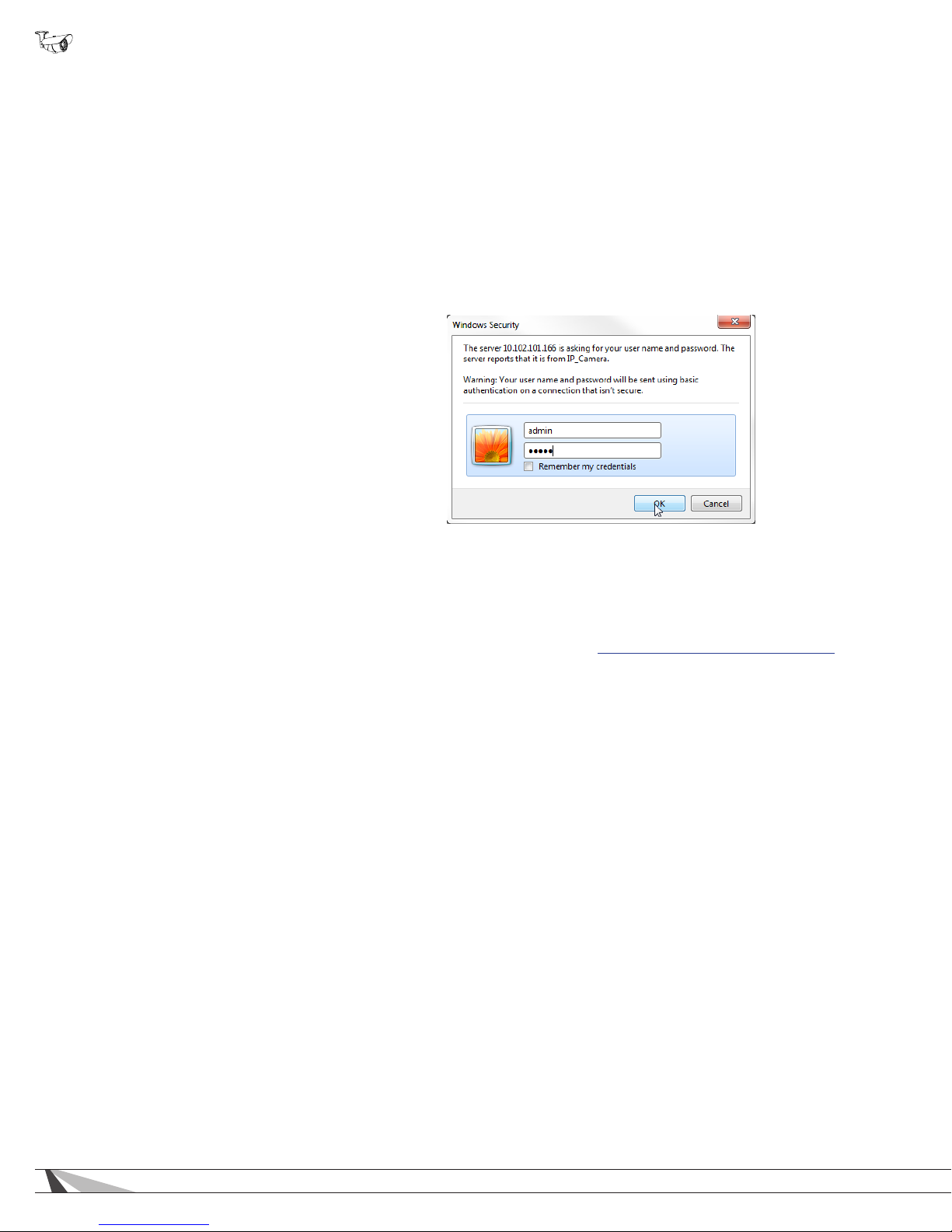
You may also access the web interface from the WPS-IP Installer software by double-clicking a camera in the device list.
C. A dialog box will open asking for a username and password. Default settings:
• Username: admin
• Password: admin
8.1.1. Recommendations for Best Web Viewing Performance
• As the number of open browser windows or tabs increases, the risk of slowed response time to the cameras increases. Avoid
keeping more than four separate browser windows open that are connected to cameras.
• Depending on the speed of the network and the Internet connection at the installation, it may be necessary to change video
streaming settings. If access is regularly interrupted or very slow, see section 9.4.4. Video Streaming 1 and 2 Setup to optimize
these settings.
16
Page 17
WPS-750-BUL-IPH Installation Manual
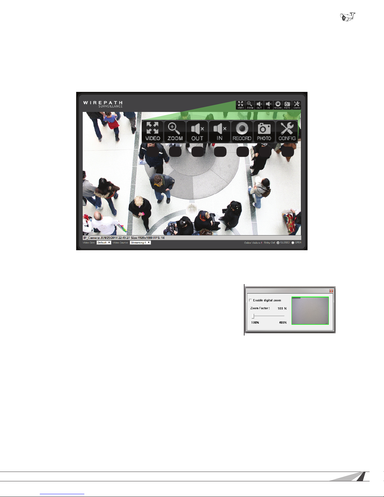
8.2. Camera Web Browser Interface
The web browser Home screen displays video and current information from the camera feed. The camera name, time signature,
video frame size and frames per second (FPS) being streamed are all displayed by default. Use the drop-down menus and buttons
to interact with the cameras inputs and outputs, change the stream, or enter the setup menus.
8.2.1. Web Interface Layout - Top Bar
(Buttons are enlarged for reference)
1 2 3 4 5 6 7
1. Video (Full-screen Mode)
Click to expand the view to full-screen mode. Press the Escape key or double-click the full-screen image to return to the
standard Live View screen.
2. Zoom (Digital Zoom Window)
Clicking Digital Zoom opens the Digital Zoom window. Use the slider to
magnify the camera view to a small area of the screen.
The Live View will only remain at this zoom level and area selection for the
current viewing session. When the user leaves Live View, the zoom level
resets to 100%.
3. Audio Out
Click to toggle audio to the built-in speaker/Audio Out port on or off.
4. Audio In
Click to toggle the camera microphone on and off.
5. Record
Record the current live stream to an .AVI video le that is saved to the PC or a network drive. A window opens for selecting
the storage location each time recording is started. Press Record again to stop the recording. The quality of this recording will
vary based on the bandwidth of the connection to the camera and the processing power of the local computer.
6. Photo
Takes a JPEG snapshot of the current image that can be saved to the PC or a network drive.
7. Cong
Click to enter the Conguration menus. All network and camera settings are congured in this menu. You must be logged in
with administrator privileges to access the Conguration Menu.
© 2014 Wirepath Surveillance
17
Page 18
WPS-750-BUL-IPH Installation Manual
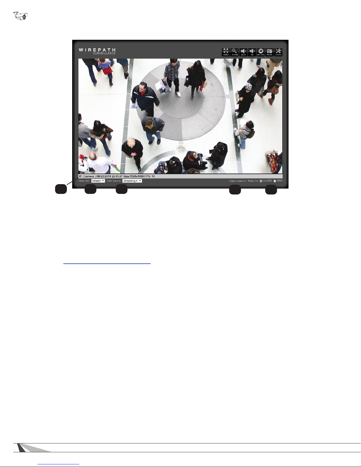
8.2.2. Web Interface Layout - Bottom Bar
1 2 3
1. Information Bar
Displays basic information about the camera feed.
2. Video Size
Adjusts the size of the Live View area within the browser window.
3. Video Source (If Streaming 2 is enabled)
Allows for selection of one of two video streams from the camera. Typically, Streaming 1 is congured for a high resolution
stream for viewing over a faster connection, and Streaming 2 is to a lower resolution for viewing over slower connections. See
section 9.4.3. Video Settings Menu Overview for information about streaming features and setup.
4. Online Visitors
Displays the number of users (all permission levels) currently logged in to view the camera. If anonymous viewing is allowed,
all anonymous viewers will also be counted. If you are the only user, then the number will be 1, unless an NVR is attached,
which will add 2 users to the count.
5. Closed/Open Buttons
Click the buttons to toggle the built-in relay on the camera.
4 5
18
Page 19
WPS-750-BUL-IPH Installation Manual
9. Camera Conguration Menu Setup
After browser access to the camera has been established, the remaining steps for setup may be completed so that cameras are
remotely viewable (from inside and outside of the LAN) but secure from unwanted access.
9.1. Conguration Menu - Access and Navigation
9.1.1. Accessing the Menu
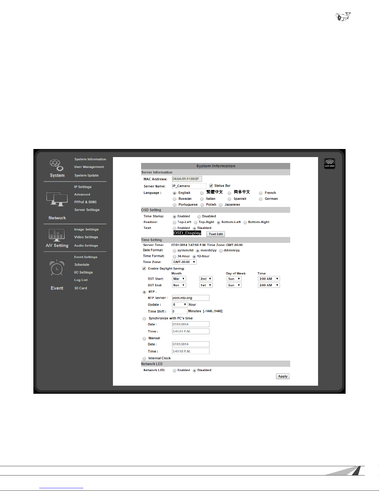
To change settings in the cameras, click the “Cong” button in the top right corner of the Live View screen.
Important! If you click “Cong” while logged in under a guest account (any account except the root “admin”
account) you will be prompted for a log in. You must enter the “admin” credentials to access the menu.
9.1.2. Conguration Menu Layout
The the left column of the Conguration menu screen contains the navigation links for all Conguration sub-menus. The rst submenu, System Information, appears by default:
9.1.3. Conguration Menu Guidelines
• When changing settings, some values will be saved automatically. Others require that an “Apply” button be clicked to save the
change. Navigating away from pages with an “Apply” button without saving will cause settings to revert. Be sure to scroll down
to the bottom of any menu before navigating away to check for an option to apply the setting, or refer to the manual.
© 2014 Wirepath Surveillance
19
Page 20
WPS-750-BUL-IPH Installation Manual
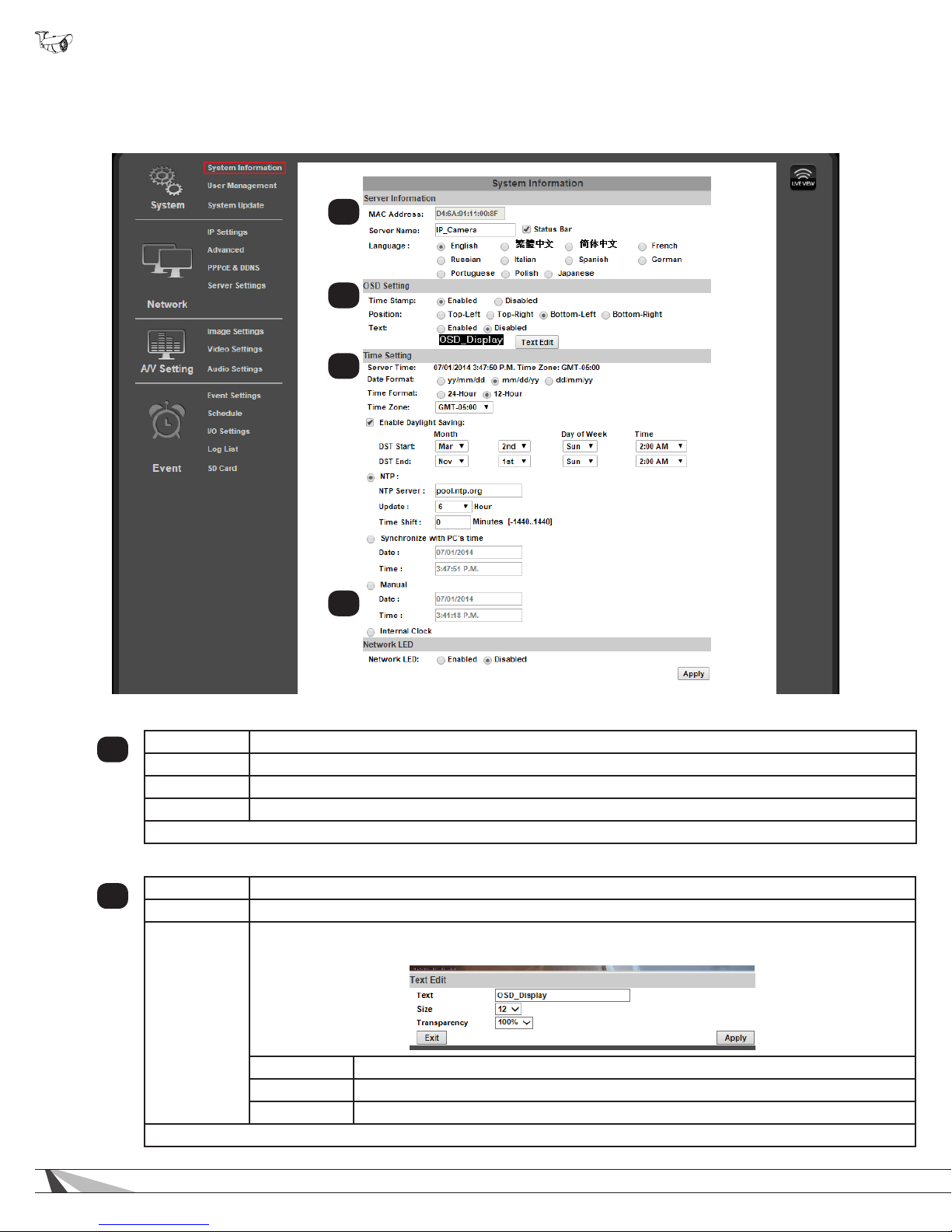
9.2. System Information and Settings
9.2.1. System Information Menu Settings
• Navigation: Log in as an administrator. From Home Screen, click “Cong” button in top right corner.
1
2
3
9.2.1.1. Server Information
MAC Address Cannot be changed. Use the MAC address to identify a camera if IP settings have been lost.
1
Server Name Modify the name given to the camera during IP Installer Setup. (Limited to 31 characters)
Language Select the desired language for camera software text.
Status Bar (Check box option to right of Server Name eld) Check to display the status bar in the camera image.
Click “Apply” at the bottom right of the page to save modied settings.
9.2.1.2. OSD Setting
Time Stamp Select whether the camera’s time and date information are recorded and transmitted with video.
2
Position (If Time Stamp is enabled) Select where the OSD stamp text and system information appears.
OSD_Display Click the Text Edit button to enter OSD_Display Text Editor:
4
Text Enter text to be displayed beside the System Time and Date.
Size Set the point size of the OSD text using the drop-down.
Transparency Set the transparency of the OSD text to be more or less visible.
Click “Apply” at the bottom right of the page to save modied settings.
20
Page 21
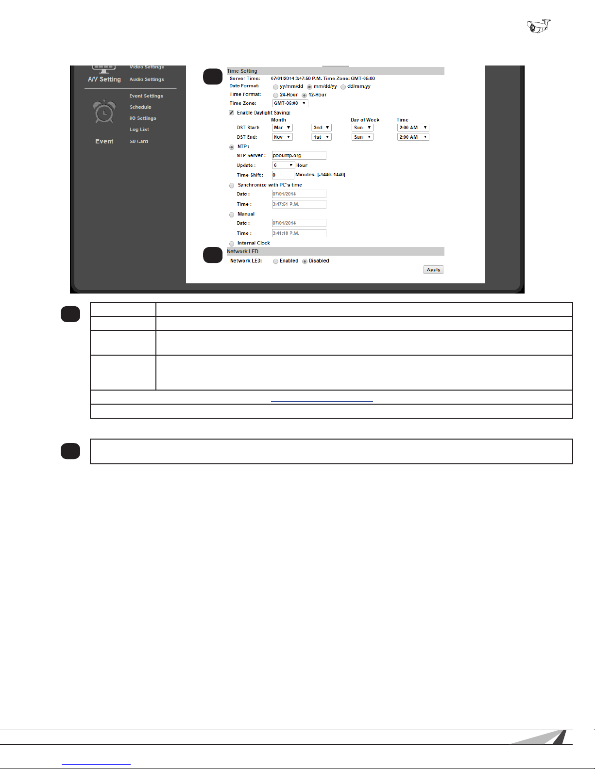
9.2.1.3. Time Setting
WPS-750-BUL-IPH Installation Manual
3
4
Server Time Current time based on the settings saved in the camera.
3
Date Format Select the order in which days (d), months (m), and years (y) are displayed.
Time Zone
Enable
Daylight
Savings Time
Time setup options are detailed in section 9.2.2. Camera Time Setup.
Click “Apply” at the bottom right of the page to save modied settings.
9.2.1.4. Network LED
Enable or disable the network status lights on the RJ45 connector (back of the camera) The LEDs are useful for setup
4
and diagnostics, but may cause unwanted color reections behind the camera during regular use.
(Only available for NTP and Manual mode) Set the camera time zone in hours ahead of or behind
Greenwich Mean Time (GMT).
Check to enable Daylight Savings Time Settings. When this setting is enabled, DST start and end times
may be set. Default times are standard for most participating regions.
© 2014 Wirepath Surveillance
21
Page 22
WPS-750-BUL-IPH Installation Manual
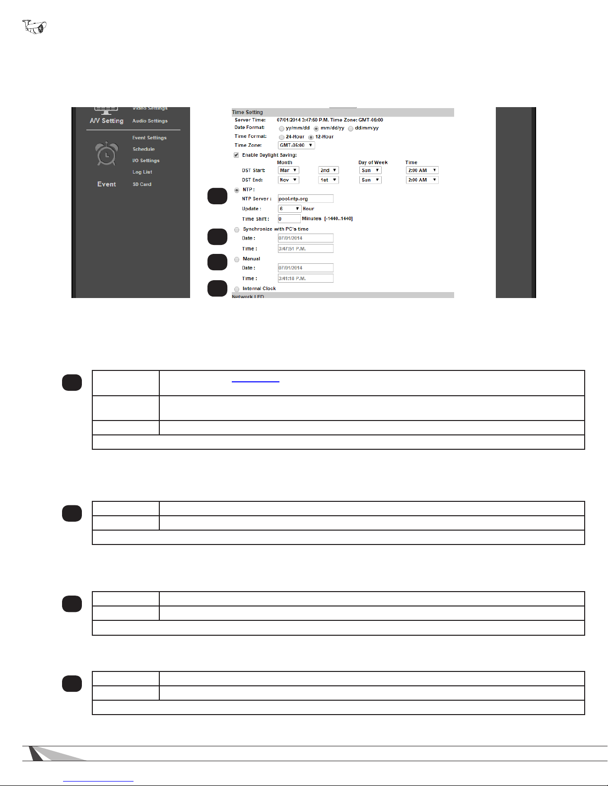
9.2.2. Camera Time Setup
Important! Wirepath™ Surveillance strongly recommends using the “NTP” time setting option unless Internet
access is not available from the camera network. Other settings may not keep the correct time after power
outages or other failures.
1
2
3
4
9.2.2.1. NTP Time
Network Time Protocol (NTP) Servers are computers on the Internet that provide reliable time and date values for other equipment.
NTP values are synchronized to be accurate to Coordinated Universal Time (UTC). Using NTP for time synchronization ensures
the most accurate time possible for recorded footage. This setting should be used as long as the camera can access the Internet at
least some of the time.
NTP Server
1
Update
Time Shift Shift the camera time forward or behind by any number of minutes from the NTP time. Default: 0.
Click “Apply” at the bottom right of the page to save modied settings.
9.2.2.2. Synchronize with PC’s Time
Synchronizes to the connected PC’s time setting. Not recommended unless the camera cannot access the Internet. The time will be
updated when the PC logs in and connects to the camera.
Date Current date the camera is receiving from the PC.
2
Time Current time the camera is receiving from the PC.
Click “Apply” at the bottom right of the page to save modied settings.
9.2.2.3. Manual
Manually set the camera date and time settings. Should not be used unless there is a special need to synchronize to a nonstandard time at regular intervals.
Date Set the desired date.
3
Time Set the desired time.
Click “Apply” at the bottom right of the page to save modied settings.
Default setting is pool.ntp.org, the most widely used NTP server. Change the server only if directed to
do so by the network administrator.
Select how often to check for time updates from the drop-down. Do not set the value to “None” or the
camera will never update if the time becomes inaccurate. Selection 1-48 hours. Default: 6 hours.
9.2.2.4. Internal Clock
Uses the last setting for date and time found in the camera and cannot be changed. This setting should not be used.
Date Current date the camera is receiving from the PC.
4
Time Current time the camera is receiving from the PC.
Click “Apply” at the bottom right of the page to save modied settings.
22
Page 23
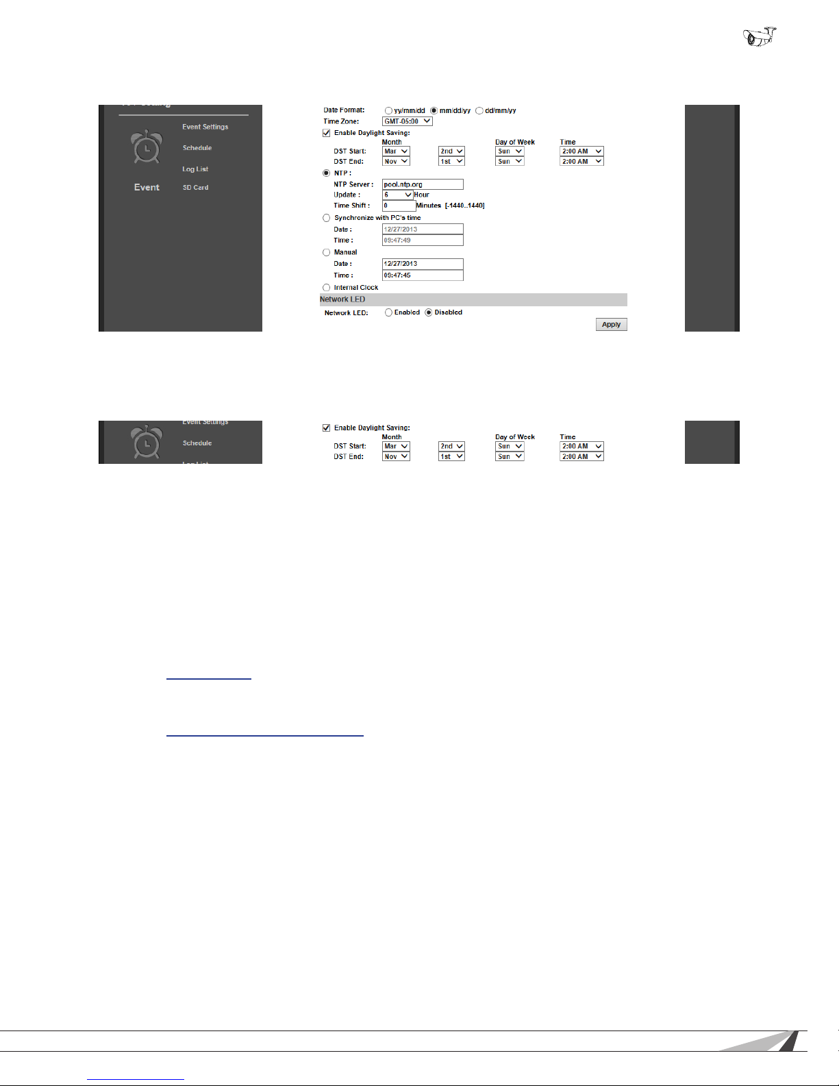
9.2.2.5. NTP Setup Instructions (For Cameras with Internet Access)
A. Set the Time Setting option to “NTP”.
B. Set the desired Date Format and Time Zone.
C. If applicable to your region, check the box to enable Daylight Savings Settings:
WPS-750-BUL-IPH Installation Manual
• Default DST settings are standard for most regions.
• If changes are required, set the Month, Week, Day of Week, and Time for the DST “Start” and “End”.
D. Enter “pool.ntp.org” in the “NTP Server” eld. Only use a different setting if instructed to do so by the network administrator.
E. 6 hours should be a sufcient setting for time updates. If constant or regular power outages occur, or Internet access is
restricted at certain times, the setting may be decreased or increased.
F. Time shift may be set to a positive or negative number of minutes if the camera time must be off by a set amount. Do not use
this setting to alter the time for Daylight Savings Time.
G. Click “Apply” at the bottom right of the page to save any changes made. Settings are now complete.
9.2.2.6. Time Setup for Cameras without Internet Access
For IP cameras connected to isolated networks, time may be manually synchronized to a separate system using the “Manual”
setting (section 9.2.2.3. Manual). This is ideal for locations where the camera may not be accessed for long periods, as long as
power is stable.
If the camera will be regularly accessed by a mobile PC, the best way to set the time is to use the “Synchronize with PC’s Time”
setting (section 9.2.2.2. Synchronize with PC’s Time). This will reset the camera time each time it is accessed. The PC will be much
more likely to have accurate settings, since it also connects to other networks and the Internet.
© 2014 Wirepath Surveillance
23
Page 24
WPS-750-BUL-IPH Installation Manual
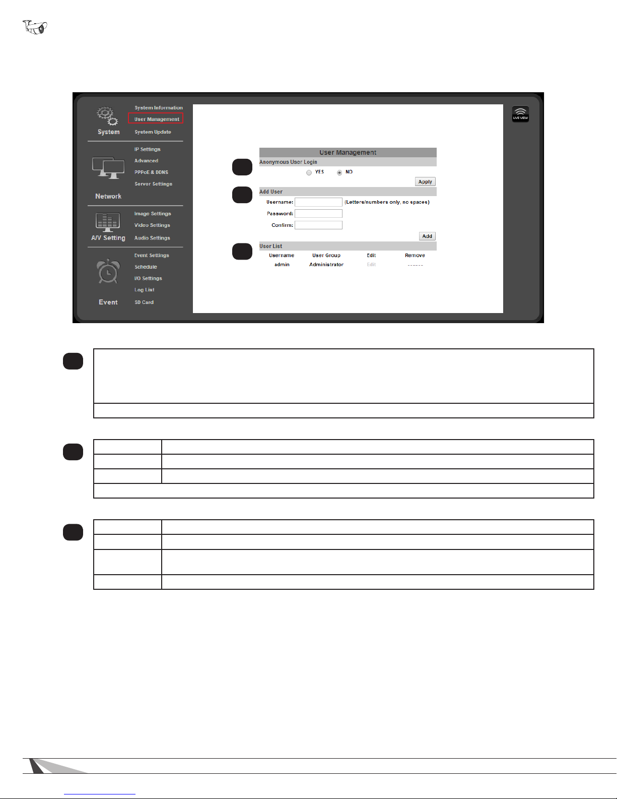
9.2.3. User Management
• Navigation: Log in as an administrator. From Home Screen, click “Cong” button in top right corner, then click “User
Management” in left column “System” sub-menu.
1
2
3
9.2.3.1. Anonymous User Login
Enabling this feature allows anyone that visits the address of the camera to:
1
9.2.3.2. Add User (Guest Account only)
2
9.2.3.3. User List
3
9.2.3.4. User Account Levels
• Administrator — Has access to all functions of the Camera and all conguration menus. Only one Administrator account may
be created, and the account may not be removed. The username or password may be modied.
• View video
• Use Zoom, Mute, Video (Full), Record, and Picture
• Change the GUI size
Click “Apply” to the right of the option buttons to save modied settings.
Username Enter a username containing letters and numbers.
Password Enter a password for the account containing letters and numbers.
Conrm Enter the same password again to conrm the new account password.
Click “Add” to the right of the elds to save modied settings.
Username Displays registered usernames that have been set up.
User Group Displays whether the user is an Administrator
Edit
Remove (Guest Accounts only) Click to remove the user account.
Click the edit button to change the administrator username or password, or the password of a guest
account. (Usernames for guest accounts cannot be changed, only deleted or added.)
• Guest — Has access to view the Camera and limited control for saving recordings and photos. No conguration menus are
accessible. Guests attempting to access to the camera conguration will be prompted for the Administrator username and
password.
Once a guest username is created, only the password may be changed. To edit the account username, delete the username
entry and re-enter it.
24
Page 25
WPS-750-BUL-IPH Installation Manual
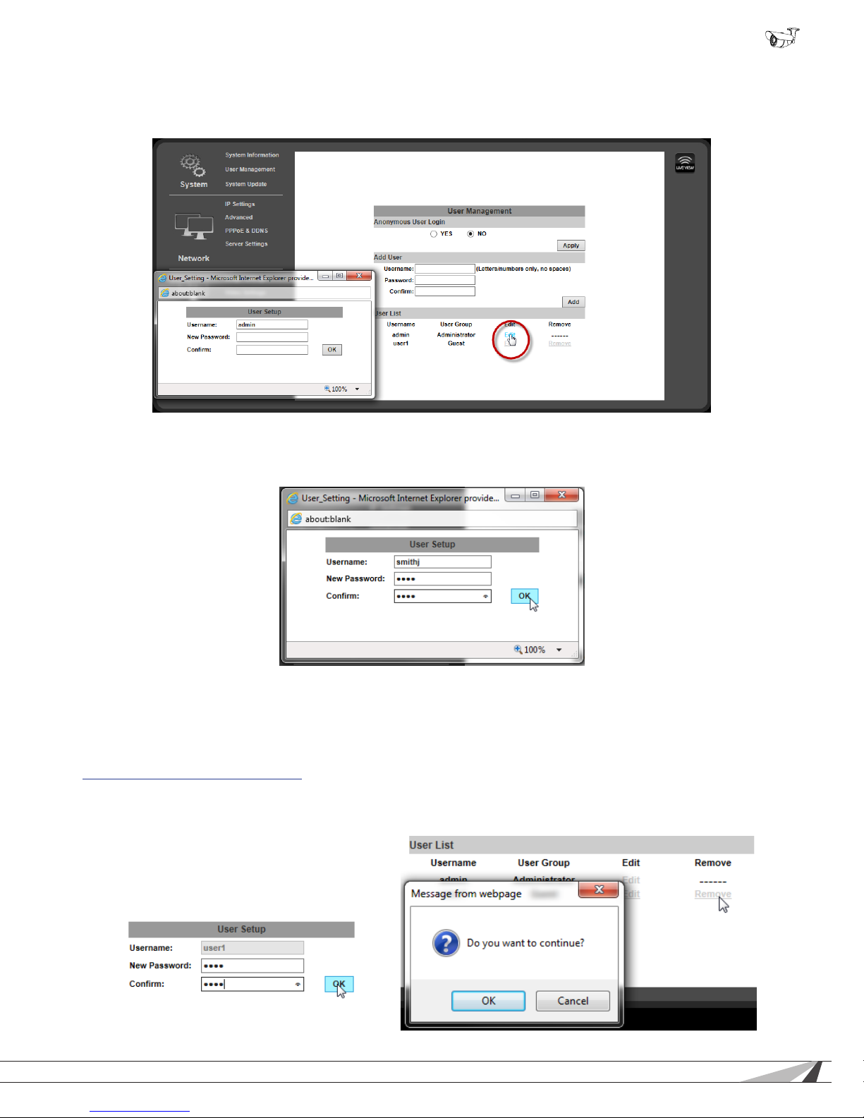
9.2.3.5. Administrator Account Setup
Once the camera is accessible on the network, the administrator password should be changed to prevent unwanted access. Select
a new password up to ten characters in length made up of letters and numbers (no punctuation or symbols).
A. Click the “Edit” button next to the username “admin” in the User List to open the User Setup window.
B. Change the Administrator username and enter a new password, or re-enter the existing password in each password eld, then
click “OK” to save the changes.
C. After selecting OK, the camera will automatically log out. Enter the new log-in information in the pop-up and sign back into the
camera as normal to continue setup. Be sure to record the Administrator account information in a safe place. If administrator
account access is lost, a manual reset of the camera is required.
9.2.3.6. Add, Edit, or Remove a Guest Account
To create a new Guest account, enter the desired username and password in the elds as indicated on the previous page in section
9.2.3.2. Add User (Guest Account only), and then click the “Add” button to add the new user.
After a Guest account has been created, the password may be changed by clicking the “Edit” button in the User List. To change the
username, a new account must be created and the old one removed.
© 2014 Wirepath Surveillance
25
Page 26
WPS-750-BUL-IPH Installation Manual
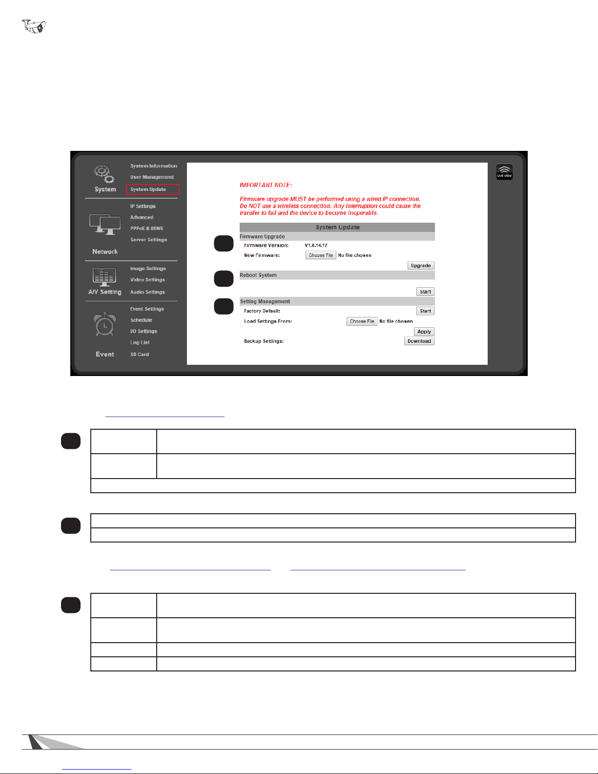
9.2.4. System Update
• Navigation: Log in as an administrator. From Home Screen, click “Cong” button in top right corner, then click “User
Management” in left column “System” sub-menu.
Important! Updating Firmware MUST be performed over a wired IP connection to the device to ensure that a
connection is sustained throughout the process. If connection is lost during update, use the IP Installer to
nd the device again and restart the update.
1
2
3
9.2.4.1. Firmware Upgrade
See section 9.2.4.6. Upgrade the Firmware for instructions on using this feature.
Firmware
1
Version
New
Firmware
Click “Upgrade” (to the right) to upload the selected rmware in the “New Firmware” to the camera.
9.2.4.2. Reboot System
Reboot the Camera. No settings are changed.
2
Click “Start” to reboot the camera.
9.2.4.3. Setting Management
See sections 9.2.4.4. How to Back up Camera Settings and 9.2.4.5. Load Backup Settings to the Camera for instructions on using
this feature.
Factory
3
Defaults
Load Settings
From:
Apply Click the “Apply” button to load the backup le to the camera.
Remove (Guest Accounts only) Click to remove the user account.
Current rmware version installed on the camera.
Click “Browse” to search for a rmware le to upload from the PC to the camera.
Reset all settings to default. Click “Start” to begin the process.
Click “Browse” to select a folder on the PC to load a camera backup le from.
26
Page 27
WPS-750-BUL-IPH Installation Manual
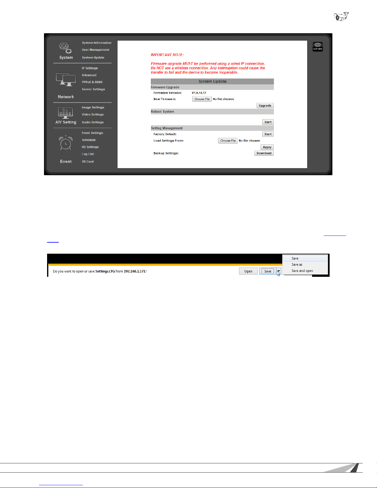
9.2.4.4. How to Back up Camera Settings
Once the settings for a camera have been set up, they can be downloaded to a conguration backup le in case the camera is
reset or must be replaced later. This le saves ALL settings from the conguration menus that can be modied.
A. On the System Update page under the Setting Management sub-menu, click the Backup Settings: Download button on the
right.
B. (Internet Explorer only) A ribbon will appear on the bottom bar of the screen asking what you want to do with the “Settings.
CFG” File. Click “Save As” so you can select the folder in which you want to save the le.
Depending on their security settings, some browsers may display a similar pop-up before the le can be saved. Allow the le to
be downloaded and select the location for it using the “Save As” feature.
C. (All Browsers) Select the location for the le from the window and then click “Save”. The le will download to the location.
9.2.4.5. Load Backup Settings to the Camera
Load backed up settings to a camera after a rmware update, if camera access is lost, or to the new camera if it must be replaced.
Backup les are saved with the sufx “.cfg”. DO NOT attempt to upload other le types or rmware les with
modied sufxes to the camera.
A. On the System Update page, under the Setting Management sub-menu, click the Load Settings From: Browse button on the
right.
B. Browse the PC for the le and select it using the window. Click the Open button to return to the camera interface in the main
browser window.
C. Click the Apply button below the Browse button on the right.
D. The camera will be updated with the settings in the le. After the update, it may be necessary to log into the camera again to
regain access.
© 2014 Wirepath Surveillance
27
Page 28
WPS-750-BUL-IPH Installation Manual
9.2.4.6. Upgrade the Firmware
Important! Updating Firmware MUST be performed over a wired IP connection to the device to ensure that a
connection is sustained throughout the process. If connection is lost during update, use the IP Installer to
nd the device again and restart the update.
A. Check for the latest rmware from the support page for the camera in use at www.SnapAV.com. If the rmware version in the
camera is below the version on the site, the rmware should be updated.
B. Download the rmware to the PC that will be used to complete the upgrade.
C. Ensure that all devices are on wired network connections.
D. On the System Update page, under the Setting Management sub-menu, click the New Firmware: Browse button on the right.
E. Browse the PC for the le and select it using the window. Click the Open button to return to the camera interface in the main
browser window.
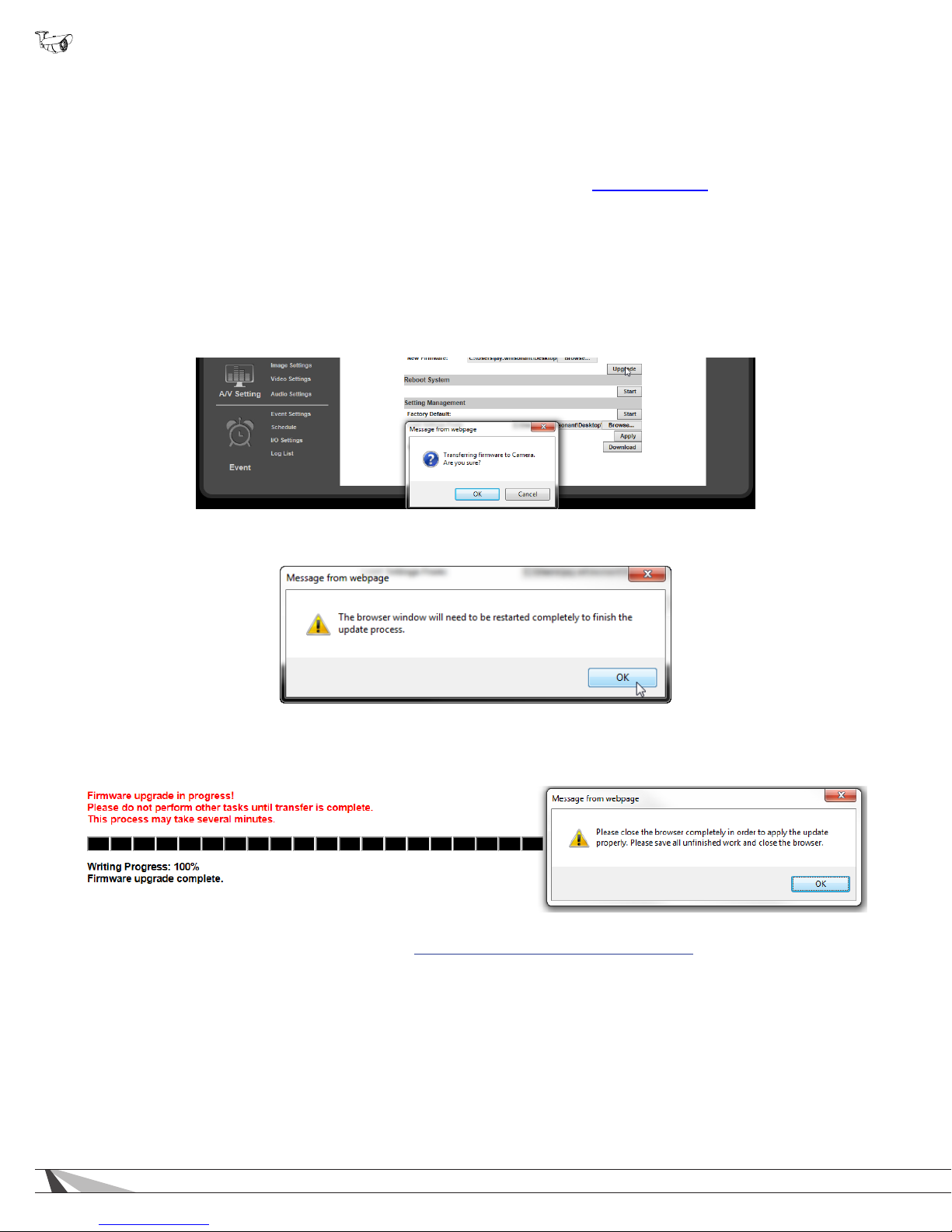
F. Click the Upgrade button below the Browse button on the right. A message will appear (below). Click “OK”.
G. Another message will appear. Click Okay, and the update will begin. Do not close or use the browser until prompted by the
update process.
H. After the update completes, the browser will prompt you to restart. Click “OK”, then close and restart the browser. The camera
will be visible on the IP Installer if the IP address has changed.
Important! The browser MUST be closed and restarted for the update process to complete correctly.
I. After completing the update, check the settings on the camera. If they have reverted to default, a backup le may be loaded if
one was saved prior to the update. See section 9.2.4.5. Load Backup Settings to the Camera.
J. The camera will be updated with the settings in the le. After the update, it may be necessary to log into the camera again to
regain access.
28
Page 29
WPS-750-BUL-IPH Installation Manual
9.3. Network IP Settings
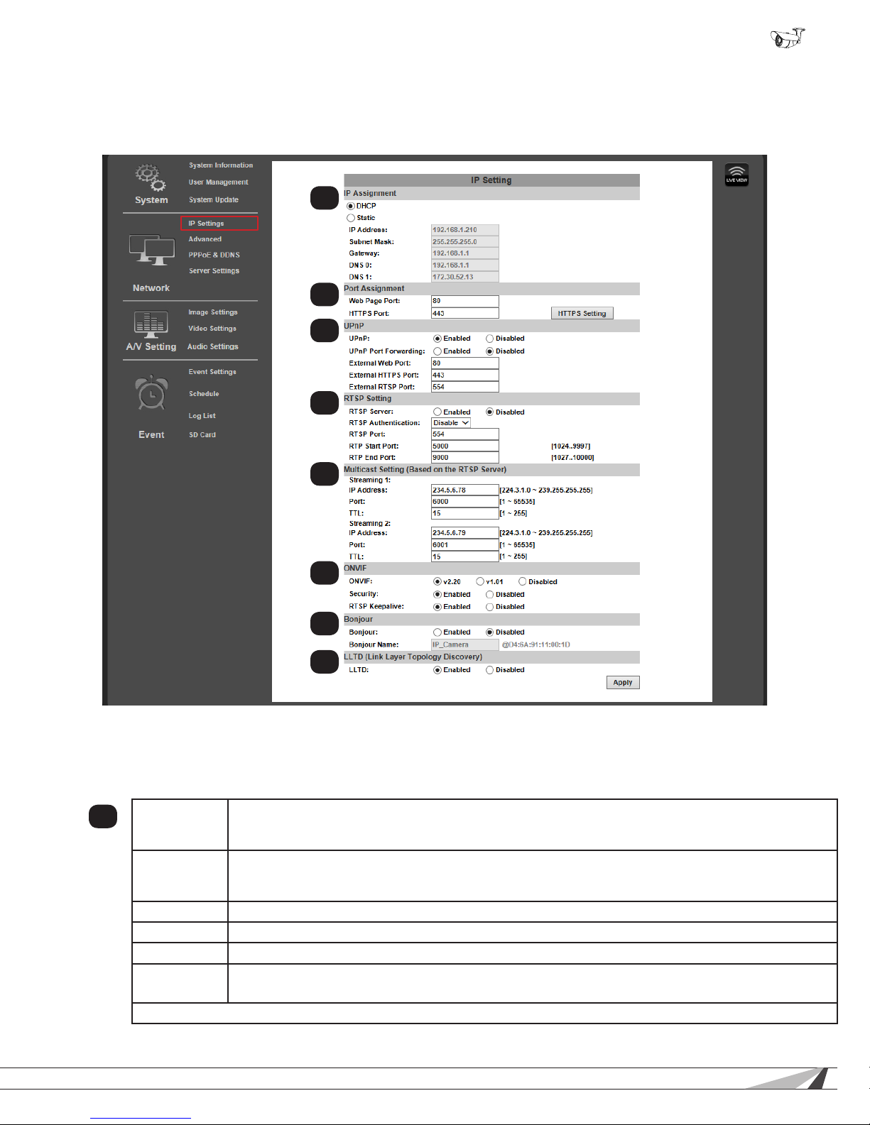
• Navigation: Log in as an administrator. From Home Screen, click “Cong” button in top right corner, then click “IP Settings”
in left column.
9.3.1. Basic IP Settings
1
2
3
4
5
6
7
8
9.3.1.1. IP Assignment
Important! These settings are required for the camera to communicate correctly at all times. Use only static
IP addresses. Contact the network administrator if you are unaware of what the settings should be or cannot
access the network for setup.
1
DHCP/Static
IP Address
Subnet Mask Subnet mask of the camera’s subnet. (For smaller networks, usually 255.255.255.0, found in the router)
Gateway IP address of the router as seen by the network. (Found in the router)
DNS 0 Domain Name Server of the camera network. (Found in the router)
DNS 1
Click “Apply” at the bottom right of the page to save modied settings.
Select IP address type. Set to DHCP by default so that network settings are issued by the router.
Change to a static IP address type to make changes to the IP settings. (All IP Assignment elds remain
grayed out until Static is selected.)
Current IP address of the camera. Enter a new address here to change the static IP address.
The address used must also be correctly congured for reserved use in the router. See router
documentation to correctly reserve a static IP address.
(Optional by network) Second Domain Name Server for the camera network. (Found in the router)
If no secondary DNS is set, use 0.0.0.0
© 2014 Wirepath Surveillance
29
Page 30
WPS-750-BUL-IPH Installation Manual
Basic IP Settings, Continued
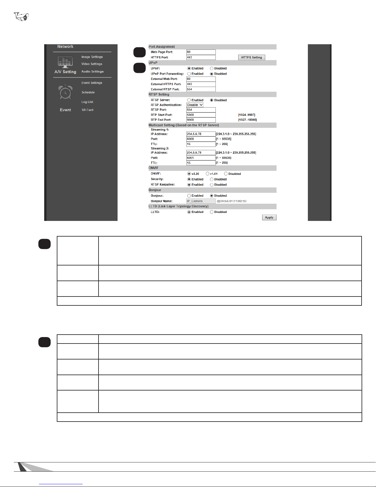
2
3
9.3.1.2. Port Assignment
2
Web Page
Port
HTTPS Port
HTTPS
Setting
Click “Apply” at the bottom right of the IP Setting page to save modied settings.
Port for accessing the camera web interface. Set to 80 by default. Each Camera must have a unique
port number in order to access from outside the local network. To make port numbering easy to
remember, use 4 digits: “8” followed by the last three numbers in the camera’s IP address. This will also
ensure that a port that is commonly used for another well-known service is not assigned to the Camera.
Used for access over the HTTPS protocol for better security. Advanced setup is required. See the
section below, “HTTPS Access Setup”.
Click this button to access HTTPS certicate setup. Advanced setup is required. See the section below,
“HTTPS Access Setup”.
9.3.1.3. UPnP
When enabled, UPnP (Universal Plug and Play) allows the camera to appear under the PC network devices. To use this feature,
UPnP must be enabled on the PC. Also contains settings for UPnP Port forwarding for use with compatible routers.
UPnP Enable or disable UPnP. Enable to allow computers to auto-discover the camera on the network.
3
UPnP Port
Forwarding
External Web
Port
External
HTTPS Port
External
RTSP Port
Click “Apply” at the bottom right of the IP Setting page to save modied settings.
Enable or disable UPnP Port Forwarding. Enable this feature to automatically congure port forwarding
on compatible routers.
External network port to be congured by a compatible router to access the Camera through HTTP.
When available, router status will be displayed to the right of this eld.
External network port to be congured by a compatible router to access the Camera through HTTPS.
When available, router status will be displayed to the right of this eld.
External network port to be congured by a compatible router to access the Camera through RTSP.
Also requires the conguration of RTSP. Router status will be displayed to the right of the eld when
available.
30
Page 31
WPS-750-BUL-IPH Installation Manual
Basic IP Settings, Continued
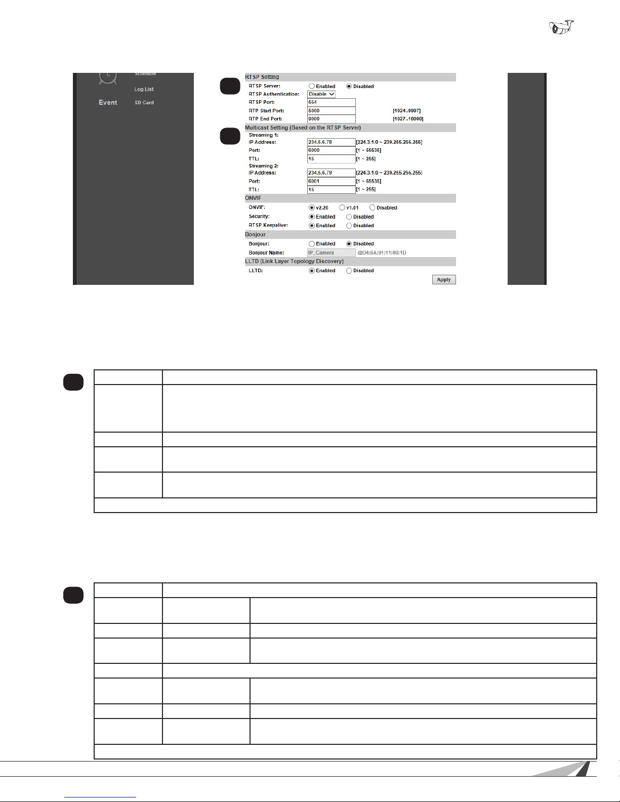
4
5
9.3.1.4. RTSP Setting
The camera supports Real Time Streaming Protocol (RTSP). RTSP is a network protocol designed to allow media devices to stream
content over Ethernet to devices on the same network or even to devices over the Internet. Instead of using a separate server or
video recorder to control the video feed to remote devices, RTSP allows direct control of the stream from within the camera. This
technology enables Wirepath™ products to stream video to devices even if they can’t support any of our remote viewing apps. Leave
RTSP disabled if it will not be used.
RTSP Server Enable or disable RTSP. If RTSP is disabled, no connection can be made using the protocol.
4
RTSP
Authentication
RTSP Port RTSP TCP communications port. Default: 554
RTSP Start
Port
RTSP End
Port
Click “Apply” at the bottom right of the page to save modied settings.
“Disable” means that everyone who knows your camera’s IP Address can link to your camera via RTSP.
No username and password are required. Under “Basic” and “Digest” authentication mode, the camera
asks for a username and password before access is allowed. The password is transmitted as a clear
text in “Basic” mode and hides it in “Digest” mode.
Start port for UDP communications (1024...9997)
End port for UDP communications (1027...10000)
9.3.1.5. Multicast Setting (Based on RTSP Server)
Multicasting delivers a single stream to multiple network recipients simultaneously. All packets are copied identically to each
recipient to save bandwidth. When using Multicast, be sure to enable the function “Force Multicast RTP via RTSP” in your media
player, then key in the RTSP path of your camera: “rtsp://(IP address)/” to receive the multicast stream. Conguration is not required
for normal camera operation. This is an advanced feature that is used for access by some third-party interfaces.
Streaming 1 Streaming output 1 settings
5
IP Address
Port Enter the port used for Multicast communication. (1 - 65535)
TTL
Streaming 2 Streaming output 2 settings
IP Address
Port Enter the port used for Multicast communication. (1 - 65535)
TTL
Click “Apply” at the bottom right of the page to save modied settings.
© 2014 Wirepath Surveillance
Enter an address for accessing the Multicast stream. (224.3.1.0 -
239.255.255.255)
Determines the number of users that can receive the stream simultaneously. Set
to a higher value to allow more users. (1 - 255)
Enter an address for accessing the Multicast stream. (224.3.1.0 -
239.255.255.255)
Determines the number of users that can receive the stream simultaneously. Set
to a higher value to allow more users. (1 - 255)
31
Page 32
WPS-750-BUL-IPH Installation Manual
Basic IP Settings, Continued
6
7
8
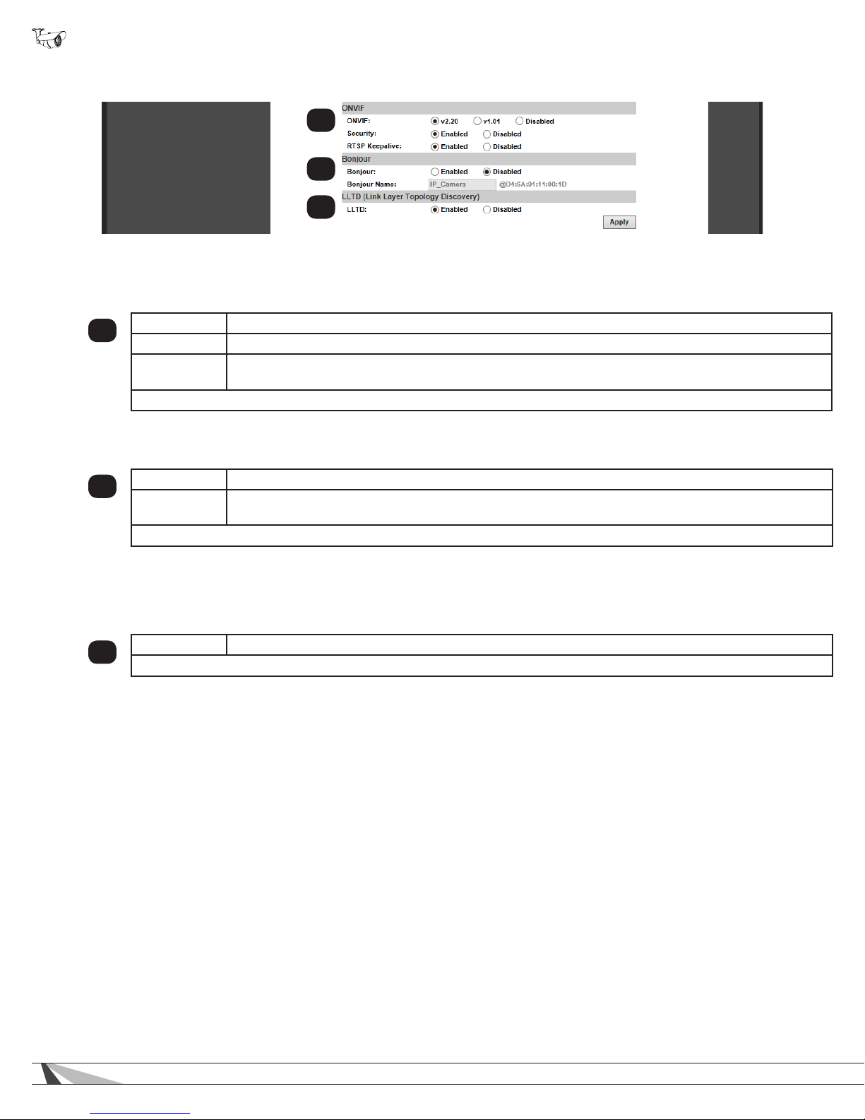
9.3.1.6. ONVIF
The ONVIF (Open Network Video Interface Forum) standard is used by IP surveillance for communication across devices from
various manufacturers. This setting does not require conguration when being used with Wirepath™ IP surveillance devices
ONVIF Select the desired ONVIF standard to be used in the camera, or disable the feature.
6
Security Enable or disable ONVIF security.
RTSP
Keepalive
Click “Apply” at the bottom right of the page to save modied settings.
9.3.1.7. Bonjour
Enabling this setting allows for the Camera to be accessed by Mac computers as a Bonjour device.
Enable or disable RTSP Keepalive. Enable if ONVIF is being used and RTSP has been congured to
ensure that the connection is kept alive.
Bonjour Enable or disable Bonjour discoverability.
7
Bonjour
Name
Click “Apply” at the bottom right of the page to save modied settings.
9.3.1.8. Link Layer Topological Discovery (LLTD)
LLTD is a proprietary Microsoft technology that displays camera connection status and properties in a PCs network map. LLTD
uses Media Access Control (MAC) addresses, not IP addresses. The PC must support LLTD and have it enabled in order to use
this feature.
LLTD Enable or disable LLTD
8
Click “Apply” at the bottom right of the page to save modied settings.
(If Bonjour is enabled) Select the custom name to be displayed in Bonjour.
32
Page 33
WPS-750-BUL-IPH Installation Manual
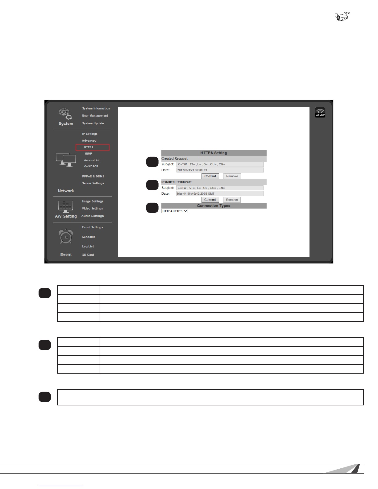
9.3.2. Advanced IP Settings - HTTPS Access Setup
Accessing the Camera through HTTPS provides an additional security level for the video stream by requiring certicate
authentication. To use this feature, a certicate must be created and then veried by a third party. To set up HTTPS access
correctly, contact the HTTPS verier.
Note: Wirepath™ Surveillance does not provide HTTPS certicates.
• Navigation: Log in as an administrator. From Home Screen, click “Cong” button in top right corner, then click “Advanced” in
left column, then click “ONVIF” from the sub-menu that opens.
1
2
9.3.2.1. Created Request
Subject Displays the subject content of the loaded certicate.
1
Date Displays the certicate creation date.
Content Click Content to display the content of the certicate. Click Remove to remove the certicate.
Remove Click Remove to remove the certicate.
9.3.2.2. Installed Certicate
Subject Displays the subject content of the loaded certicate.
2
Date Displays the certicate creation date.
Content Click Content to display the content of the certicate. Click Remove to remove the certicate.
Remove Click Remove to remove the certicate.
9.3.2.3. Connection Types
Select HTTP, HTTPS, or HTTP & HTTPS. We recommend that this be set to “HTTP & HTTPS” unless all PCs will have
3
the HTTPS certicate installed.
3
© 2014 Wirepath Surveillance
33
Page 34
WPS-750-BUL-IPH Installation Manual
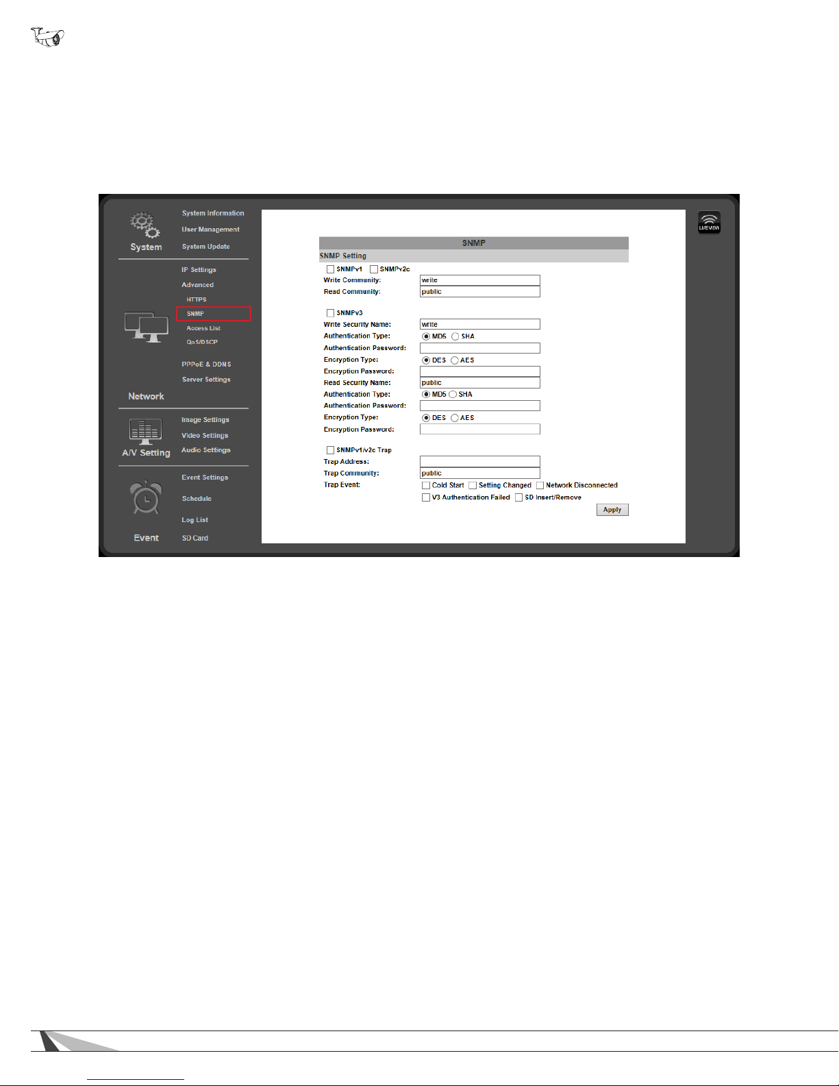
9.3.3. Advanced IP Settings - SNMP
SNMP (Simple Network Management Protocol) is used for network management of larger networks. It allows for monitoring network
devices such as IP cameras via a management host. This is an advanced setting that should be used only on larger systems.
Conguration requires consulting with the network administrator.
• Navigation: Log in as an administrator. From Home Screen, click “Cong” button in top right corner, then click “Advanced” in
left column, then click “SNMP” from the sub-menu that opens.
Setup for SNMP features vary by application. Consult with the network administrator for setup instructions.
34
Page 35
WPS-750-BUL-IPH Installation Manual
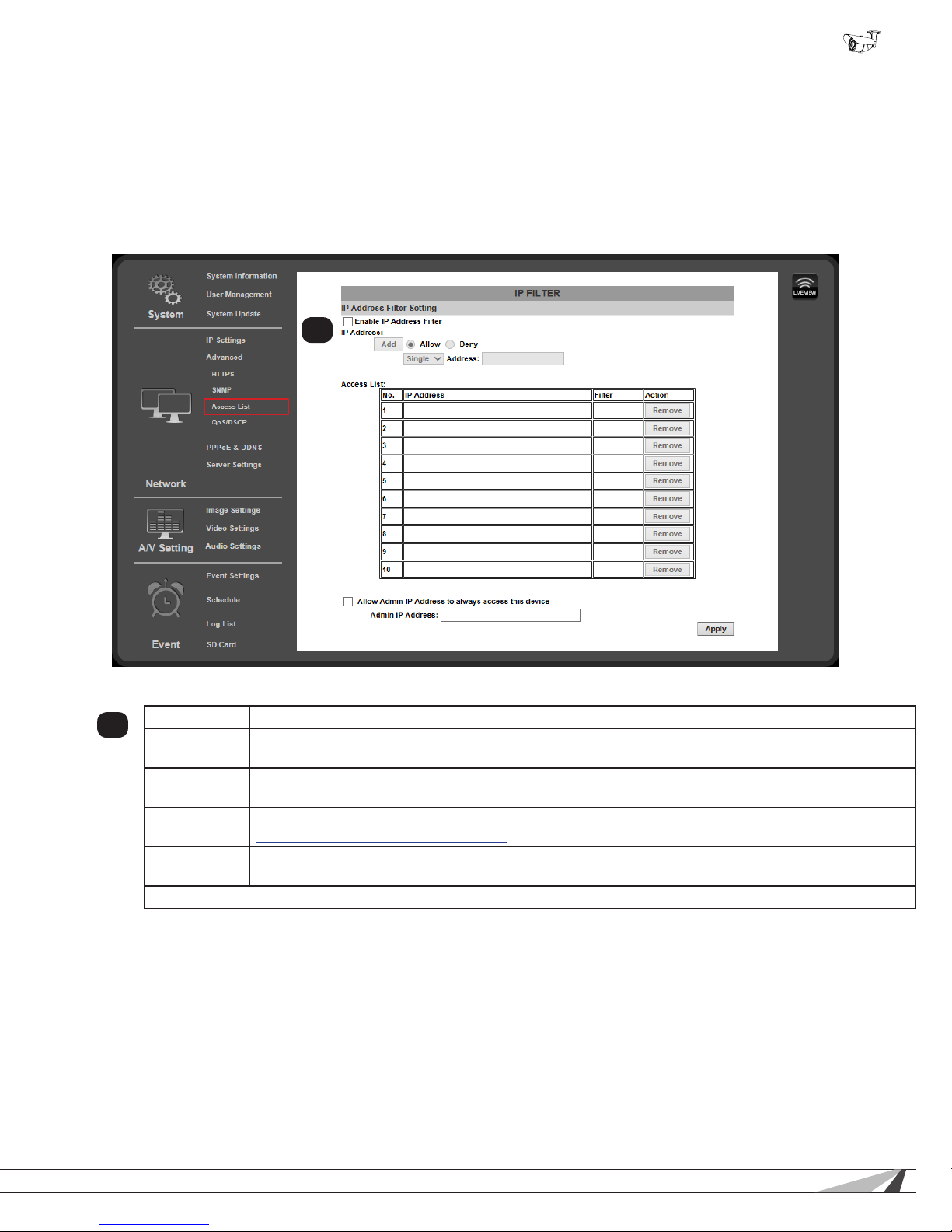
9.3.4. Advanced IP Settings - Access List (IP Filter)
IP address ltering is used to allow or deny access to the camera from individual IP addresses or ranges of IP addresses. This adds
an additional layer of security to the camera.
To ensure that the camera can be accessed by the Admin after setting up the list, the IP address of the
administrator’s PC must be enabled in the list. Or, if it is within a range of disabled addresses, select the
“Allow Admin IP Always” check box and enter the address of the Admin PC.
• Navigation: Log in as an administrator. From Home Screen, click “Cong” button in top right corner, then click “Advanced” in
left column, then click “Access List” from the sub-menu that opens.
1
9.3.4.1. IP Address Filter Setting
Enable Check the box to enable IP address ltering for all visitors.
1
IP Address
Access List Displays the IP addresses currently allowed or denied access to the camera. Click “Remove” in the
Allow Admin
IP Address...
Admin IP
Address
Click “Apply” at the bottom right of the page to save Administrator IP Address access settings.
Use this area to add IP addresses to the list for access or denial. Filtering must be enabled. See next
section, 9.3.4.2. Add or Remove IP Addresses or Ranges for instructions.
Action column on the right to delete an entry.
Check the box to restrict Administrator access to only one address. (LAN or WAN address). See section
9.3.4.3. Controlling Administrator Access for instructions.
Enter the address the Administrator will access the camera from.
© 2014 Wirepath Surveillance
35
Page 36
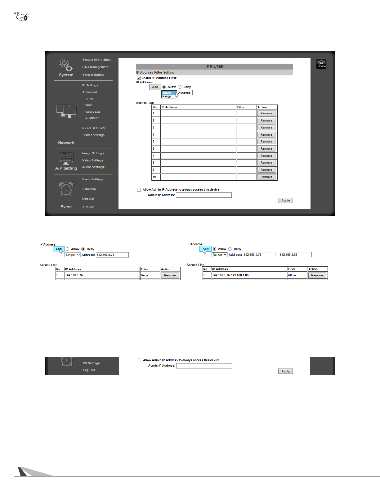
WPS-750-BUL-IPH Installation Manual
9.3.4.2. Add or Remove IP Addresses or Ranges
A. Enable IP Address Filtering to gain access to the settings:
B. Enter an IP address or range of addresses into the eld and select whether to allow or deny access:
Single IP Address: IP Address Range:
C. After clicking the “Add” button, the new entry will be added to the list.
D. Click the “Remove” button to the right to remove an entry from the list.
9.3.4.3. Controlling Administrator Access
For installations where the Administrator account is only accessed from one computer, the IP address of the computer may be
reserved. Enabling this feature prevents modication of settings on the camera from any other IP address.
Note: If another device is issued the same IP address, the new device will be granted Admin access. Be sure to use a reserved or
static IP address for the computer, or Admin rights may be lost. If this occurs, a physical camera reset is required.
A. Check the box for “Allow Admin IP Address to always access this device”.
B. Enter the IP address for the Admin computer.
36
Page 37
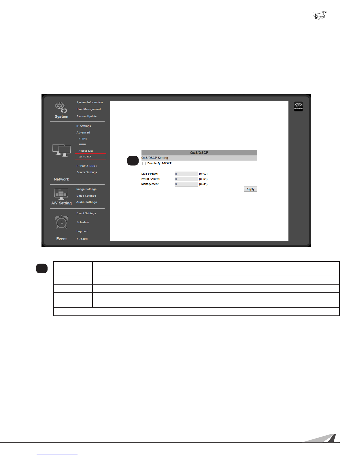
WPS-750-BUL-IPH Installation Manual
9.3.5. Advanced IP Settings - QoS/DSCP
Quality of Service (QoS) is used within a network to dene priority levels for selected trafc. This allows for a higher level
of bandwidth to be used whenever a particular type of trafc is being sent to avoid latency and packet loss. The network
administrator should be consulted before enabling this feature.
For example: Video streams require more bandwidth than email notications. By assigning a higher DSCP (Differentiated Services
Code Point) number to video streams guarantees the quality of the stream on the network.
• Navigation: Log in as an administrator. From Home Screen, click “Cong” button in top right corner, then click “Advanced” in
left column, then click “QoS/DSCP” from the sub-menu that opens.
1
9.3.5.1. QoS / DSCP Setting
Enable QoS/
1
DSCP
Live Stream Enter a DSCP value between 0 and 63 to use when live stream trafc is being sent across the network.
Event/Alarm Enter a DSCP value between 0 and 63 to use when event/alarm trafc is being sent across the network.
Management Enter a DSCP value between 0 and 63 to use when management trafc is being sent across the
Click “Apply” at the bottom right of the page to save modied settings.
Check the box to enable this feature.
network.
© 2014 Wirepath Surveillance
37
Page 38
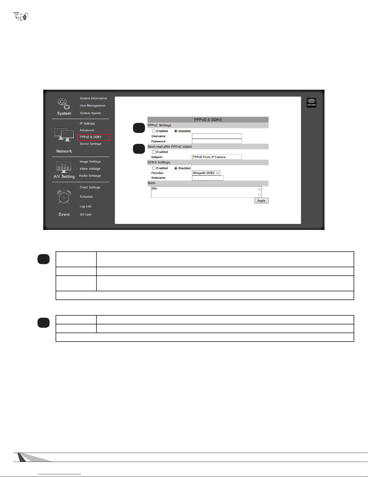
WPS-750-BUL-IPH Installation Manual
9.3.6. PPPoE Setup
9.3.6.1. PPPoE Overview
Point-to-Point Protocol Over Ethernet (PPPoE) is a network protocol primarily used with DSL (Digital Subscriber Line) providers and
modems. This protocol requires a login to connect to the modem even when a router is used. Conguration of these settings is not
required to operate the camera on a standard network.
• Navigation: Log in as an administrator. From Home Screen, click “Cong” button in top right corner, then click “PPPoE &
DDNS” in left column menu.
1
2
9.3.6.2. PPPoE Settings
Enabled/
1
Disabled
Username Enter the login name provided by the Internet Service Provider (ISP).
Password
Click “Apply” at the bottom right of the page to save modied settings.
9.3.6.3. Send Mail after PPoE Dialed
Enabled Click Enable to send an email when the PPPoE is dialed.
2
Subject Enter a subject line to be used for outgoing emails.
Click “Apply” at the bottom right of the page to save modied settings.
Turn PPPoE features on or off. Enable to use PPPoE to access the camera.
Enter the password provided by the Internet Service Provider (ISP).
38
Page 39
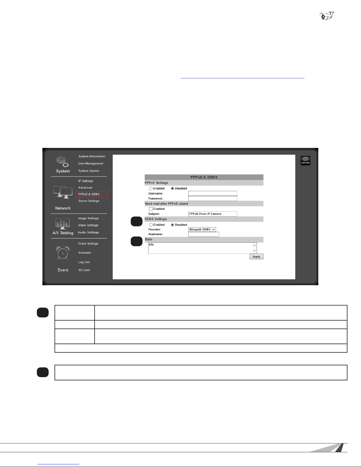
WPS-750-BUL-IPH Installation Manual
9.3.7. DDNS Setup
9.3.7.1. DDNS Overview
Dynamic Domain Name Servers (DDNS) map an alphanumeric Internet domain name to a network’s WAN IP address. When
congured, DDNS enables login to cameras from anywhere on the Internet without having to remember a numeric address that
could change on a regular basis. Conguring DDNS is not required for remote access, but makes access easier. Only one device
on the network requires DDNS setup. After one device is congured, the same address can be used to access other devices as
long as ports are set differently for each camera. (See section 9.3.7.4. Setting Up a DDNS Address – WirepathDNS)
Our free Wirepath™ DNS service is fast to set up right through the camera interface – no PC required – and it provides maximum
uptime thanks to redundant USA-based servers located across the country.
If an NVR is being used in the system, we recommend that remote DDNS access is handled through the
NVR. Only congure remote access for cameras that must be accessed from outside the local network
independently.
• Navigation: Log in as an administrator. From Home Screen, click “Cong” button in top right corner, then click “PPPoE &
DDNS” in “Network” group of left column menu.
9.3.7.2. DDNS Settings
Enabled/
1
Disabled
Provider Select a provider for the DDNS service being used. (See Overview)
Hostname Prex for the DDNS URL. Example: For DDNS address “ipdemo.wirepath.dns.com” the hostname is
Click “Apply” at the bottom right of the page to save modied settings.
Turn DDNS functionality on or off. Enable to use DDNS to access the camera from outside of the local
network.
“ipdemo”.
9.3.7.3. State (DDNS)
Displays the current state of the DDNS service. Will update within 5 minutes of assigning a DDNS and will update
2
regularly.
1
2
© 2014 Wirepath Surveillance
39
Page 40
WPS-750-BUL-IPH Installation Manual
9.3.7.4. Setting Up a DDNS Address – WirepathDNS
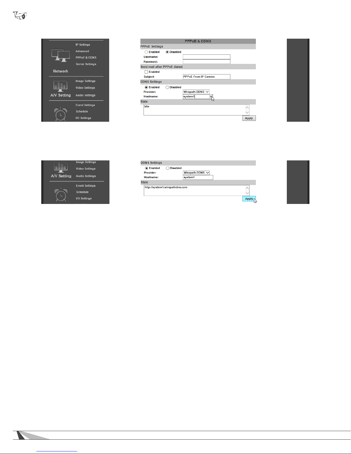
A. To use Wirepath DDNS service, enable the DDNS feature by selecting the button.
B. Enter a prex for the address in the host name eld as shown in the example above (system1).
C. Click “Apply” in the bottom right corner to save the address. After a moment, the page will reload and the address will appear in
the “State” box as shown below:
D. DDNS is now correctly set up. To complete setup for remote access, log into the router and forward the port for the camera to
its IP address.
40
Page 41
WPS-750-BUL-IPH Installation Manual
9.3.8. Server Settings
Server Settings menus allow conguration of the message and le transfer systems used by the camera to send emails, video les,
or snapshots to: email recipients, to an FTP server, or to be hosted over the local network.
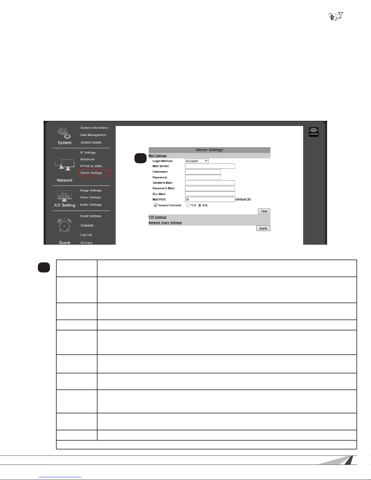
When you navigate to the Server Settings page, the Email settings will appear by default. To change settings for FTP or Network
Sharing, click the gray banner for the feature, and the settings will load for that feature. Click “Apply” in the bottom right corner to
save the settings before navigating to any menu outside of the Server Settings menu page.
• Navigation: Log in as an administrator. From Home Screen, click “Cong” button in top right corner, then click “Server
Settings” in left column menu.
9.3.8.1. Email Notications
Allows for email notications to be sent based on various triggers.
1
9.3.8.2. Mail Settings
Login Method
1
Mail Server
Username (Login Method: Account only) Enter the username for the email account being used to send
Password (Login Method: Account only) Enter the password for the email account being used to send notications.
Sender’s Mail
Receiver’s Mail
Bcc Mail Enter additional recipients as with the eld above (Receiver’s Email). These recipients will not see other
Mail Port Set the port number used by the email server to pass data out of the network. Most unsecured accounts
Secure
Connect
Test Click test to send a test email to all receivers and Bcc mail addresses when setting up notications.
Click “Apply” at the bottom right of the page to save modied settings.
Click the drop-down and select Account or Anonymous (if no login for the email account is required).
The login method used depends on the requirement of the email server being used.
Enter the address of the SMTP server. Contact the network administrator for corporate accounts (like a
Microsoft Exchange server), or the email provider for personal accounts (like Gmail or Microsoft email)
The SMTP server used must be congured for POP3 protocol.
notications. Some servers require the full email address to be entered.
Enter any email address to be used on the emails being sent. Used for notication purposes only. Use a
name that identies the camera sending the email. Example: [email protected].
Some SMTP servers might replace this information with the username of the account. This is normal.
Enter email addresses for recipients of email notications. Separate addresses with commas.
Example: [email protected], [email protected]
addressees listed in the “To:” eld of the email.
will use port 25. Secure accounts may use 465, 587, or other. Contact the email service provider or
network administrator to conrm the correct port.
Check the box to enable a secure connection when sending emails. This is required for most SMTP
servers.
© 2014 Wirepath Surveillance
41
Page 42
WPS-750-BUL-IPH Installation Manual
9.3.8.3. FTP Settings
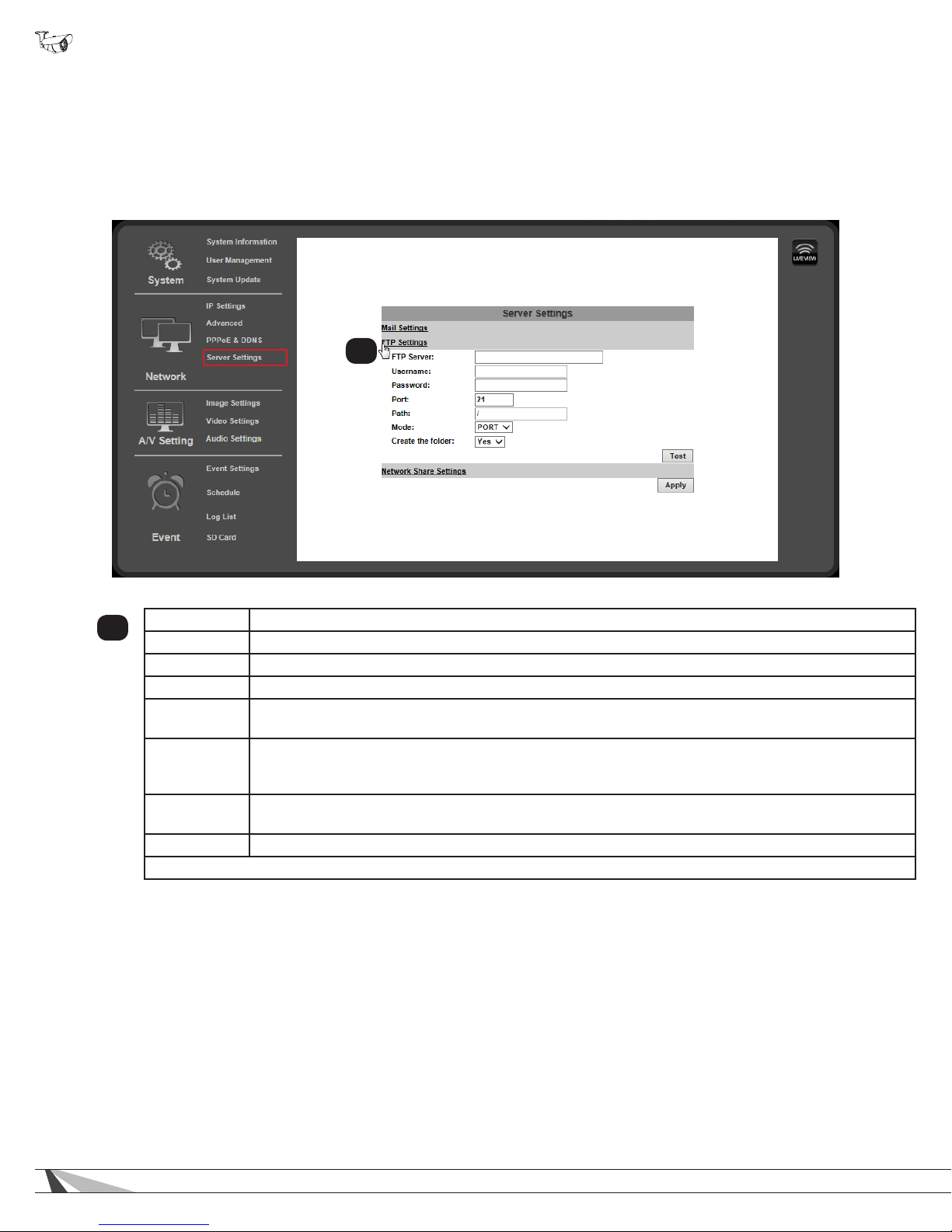
An FTP server is a remote computer server the camera connects to over the network or Internet. When an FTP server is
congured, recorded video and snapshot les can be stored on the server for later access. Contact the network administrator for
FTP server setup information.
• Navigation: Log in as an administrator. From Home Screen, click “Cong” button in top right corner, then click “Server
Settings” in left column menu. In the Server Settings sub-menu on the main window of the page, click Network Share Settings”.
1
FTP Server Enter the FTP server address to which les will be transferred.
1
Username Enter the FTP account username.
Password Enter the FTP account password.
Port Enter the port congured for FTP connections. Usually port 21.
Path
Mode
Create the
Folder
Test Click to send a test le to the FTP server to conrm that new settings are correct.
Click “Apply” at the bottom right of the page to save modied settings.
Directory for the les to be saved to on the FTP server. Avoid using spaces in le names. Use
underscores instead.
Select the data channel to use for logging into the FTP server, either “PORT” or “PASV”. This is
an advanced setting and should not be changed from “PORT” unless instructed to by the network
administrator.
Select “Yes” to have a new folder created to contain each new le. The folder will be named the same
as the le. Select “No” to save all les directly to the selected folder.
42
Page 43
WPS-750-BUL-IPH Installation Manual
9.3.8.4. Network Share Settings
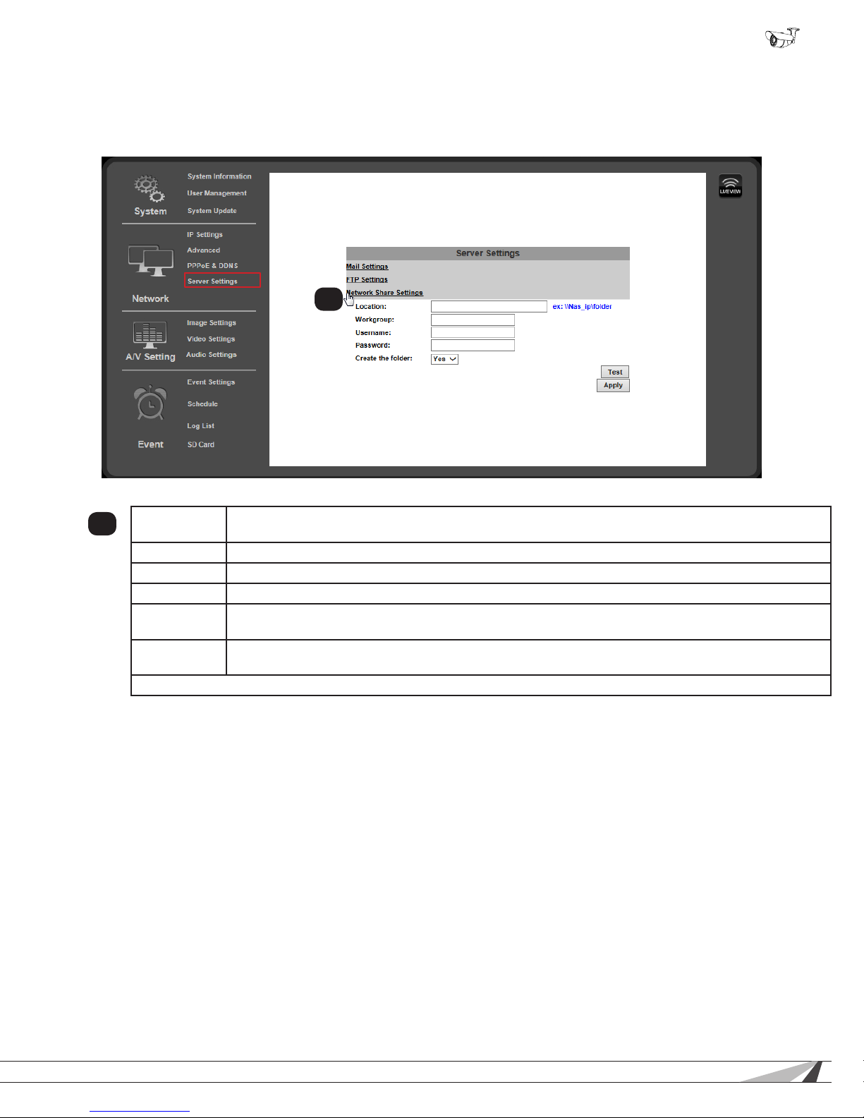
• Navigation: Log in as an administrator. From Home Screen, click “Cong” button in top right corner, then click “Server
Settings” in left column menu. In the Server Settings sub-menu on the main window of the page, click “Network Share
Settings”.
1
Location
1
Workgroup (Optional, may be left blank) Enter the Work Group name for the Network Share server.
Username Enter the Network Share server account username.
Password Enter the Network Share server account password.
Create the
Folder
Test Click the test button to send a le to the Network Share server. Use Test to conrm that new settings
Click “Apply” at the bottom right of the page to save modied settings.
Network path of the Samba/network share server and share name. The server must be identied by its
IP address and followed by the network share name. Example: \\192.168.0.250\JonesFolder”.
Select Yes to have a new folder created to contain each new le. The folder will be named the same as
the le. Select no to save all les directly to the selected folder.
are correct.
© 2014 Wirepath Surveillance
43
Page 44
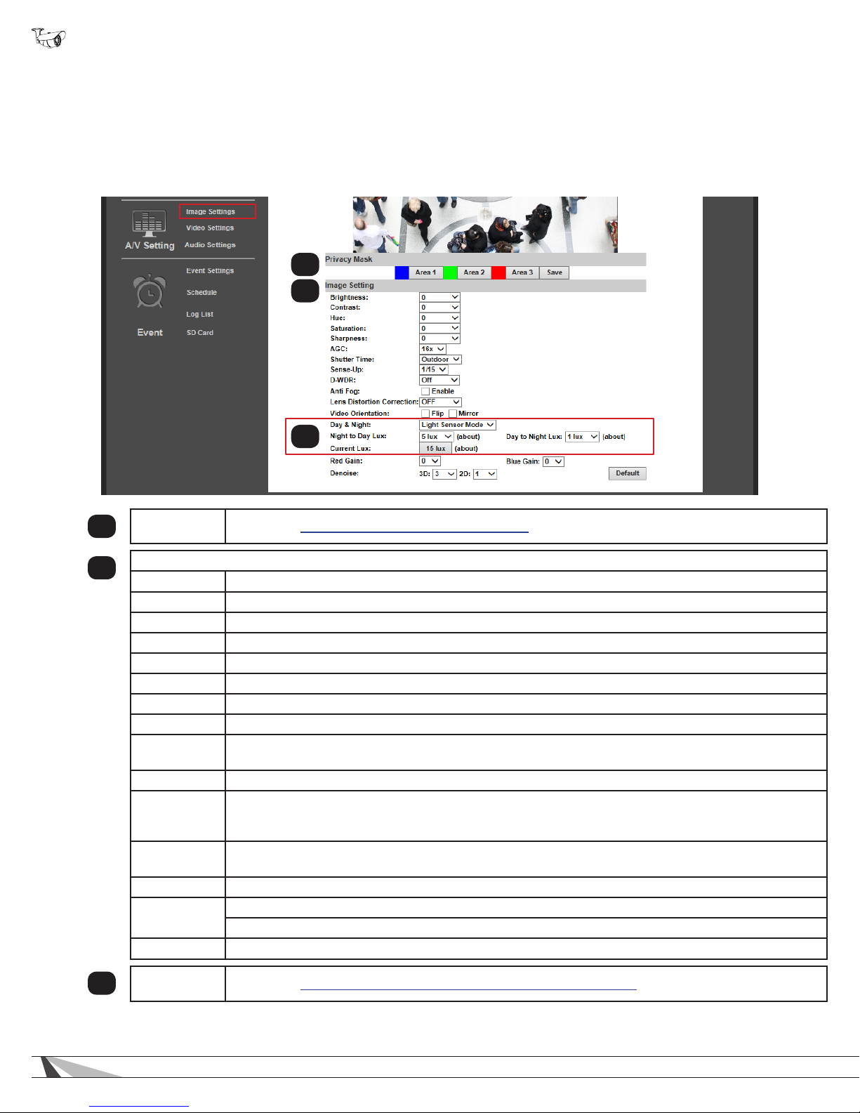
WPS-750-BUL-IPH Installation Manual
9.4. Camera A/V Settings
9.4.1. Image Settings Menu
The image setting menu is used to set up the camera view for the best image possible. Brief descriptions of the menu are given
below. Complete instructions for setup are in the following sections.
• Navigation: Log in as an administrator. From Home Screen, click “Cong” button in top right corner, then click “Image
Settings” in the left column menu.
1
2
3
Privacy Mask See section 9.4.2.5. How to Configure Privacy Masks
1
Image Setting
2
Brightness Adjust overall brightness from -4 (Low) to +4 (High). Default: zero (0).
Contrast Adjust white levels from -4 (Low) to +4 (High). Default: zero (0).
Hue Adjust the color tone (or tint) between -4 (Blue) and +4 (Red). Default: zero (0).
Saturation Adjust color intensity from -4 (Low) to +4 (High). Default: zero (0).
Sharpness Adjust edge detail from -4 (Low) to +4 (High). Default: zero (0).
AGC Auto Gain Control balances high contrast scenes. Adjust from 16x (Low) to 64x (High). Default: 16x.
Shutter Time Use automatic Indoor or Outdoor preset modes or set 1/30(Slow)-1/1000 (Fast). Default: Outdoor.
Sense-Up Set slow shutter time for use in low light areas from 1/5 (Slow) to 1/30 (Fast). Default: 1/15.
D-WDR
Anti-Fog Check Enable to clear foggy scenes using software, Default: Off.
Lens
Distortion
Correction
Lens
Orientation
Red/Blue Gain Set the red and blue balance from -5 (Low) to 5 (High). Default: 0.
Digital Noise
Reduction
Default Click to reset all Image Setting menu values.
Digital Wide Dynamic Range balances dark and bright areas in low light scenes to maintain high image
quality. Turn on and set from 1 (Low) to 8 (High). Default: Off.
Adjust the image so that curvature image distortion caused by the lens is reduced to a minimum. Turn
on and set from 1 (Low) to 8 (High). Default: Off.
Check the box for Flip or Mirror to change the image appearance. Both settings are disabled by default.
3D - Reduces noise around moving objects. Default: 5.
2D - Reduces noise around stationary objects. Default: 1.
Day & Night
3
Setting
44
See section 9.4.2. How to Configure Day & Night Settings (Color Modes)
Page 45

WPS-750-BUL-IPH Installation Manual
9.4.1.1. Tips for Getting the Best Camera Image
• Too much brightness causes the image to fade. Too little brightness will cause dark colors to run together.
• Too much contrast will cause obscured details. Too little contrast will cause the image to lose clarity and brightness.
• Too much saturation will cause colors to be inaccurate. Too little saturation will cause the image to appear black and white.
• Increase AGC only if contrast in the scene is too dark in some areas and too bright in others. Too much AGC can drastically
reduce image clarity in low-light scenes.
• Lower shutter time values increase the amount of light available, but can increase movement blur. Higher shutter time values
decrease lighting, but motion is captured more clearly.
• Leave Sense-Up OFF unless required for scenes containing very bright and dark areas at the same time (such as heavily
backlit windows).
• DNR can reduce some digital noise that occurs in dimly lit scenes. Use the lowest setting that provides adequate image quality.
© 2014 Wirepath Surveillance
45
Page 46
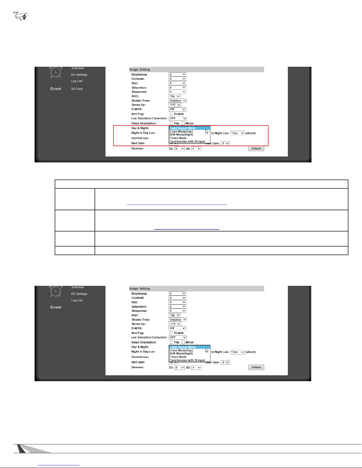
WPS-750-BUL-IPH Installation Manual
9.4.2. How to Congure Day & Night Settings (Color Modes)
The camera can record an image in color or black-and-white mode. Color mode requires more light but provides the best image
given ideal conditions. Black and white requires much less light, and the camera’s IR can be turned on to illuminate the scene.
If the camera view is not ideal after installation, adjustments can be made to optimize the automatic settings or set them manually.
9.4.2.1. Day & Night Modes
Select the mode from the Day and Night drop-down menu.
Light Sensor
Mode
(Default)
Color Mode
(Day)
B&W Mode
(Night)
Times Mode Forces camera to switch between Color and B&W modes at specic times.
Uses camera light sensor to switch between Color (Day) and B&W (Night) modes.
See section 9.4.2.3. Light Sensor Mode (Default Mode)
Forces camera to Color (Day) mode only. Useful for scenes that will be consistently lit and when color
video is always preferred. All sub-settings are disabled in Day mode. Use the Image Settings to adjust
the picture. See section 9.4.1. Image Settings Menu.
Forces camera to B&W (Night) mode only, increasing low-light performance. Useful for scenes that will
consistently be poorly lit.
If the camera view is not ideal after installation, adjustments can be made to optimize the automatic settings.
46
Page 47
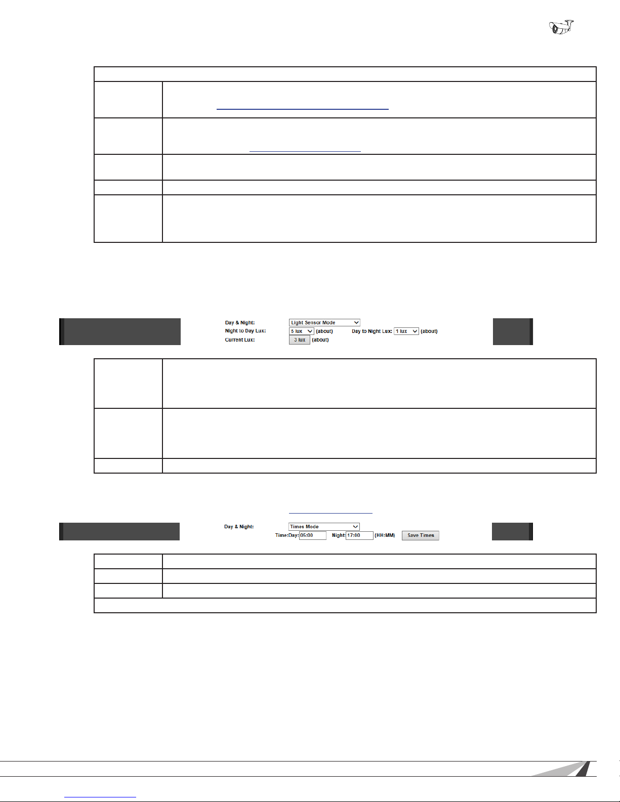
WPS-750-BUL-IPH Installation Manual
9.4.2.2. Day & Night Modes
Select the mode from the Day & Night drop-down menu.
Light Sensor
Mode
(Default)
Color Mode
(Day)
B&W Mode
(Night)
Uses camera light sensor to switch between Color (Day) and B&W (Night) modes.
See section 9.4.2.3. Light Sensor Mode (Default Mode)
Forces camera to Color (Day) mode only. Useful for scenes that will be consistently lit and when color
video is always preferred. All sub-settings are disabled in Day mode. Use the Image Settings to adjust
the picture. Section 9.4.1. Image Settings Menu
Forces camera to B&W (Night) mode only, increasing low-light performance. Useful for scenes that will
consistently be poorly lit.
Time Mode Forces camera to switch between Color and B&W modes at specic times.
Selects Color and B&W modes based on the state of a contact output from an external device (such
Synchronize
with DI Input
as a security lighting sensor) connected to the camera’s DI input. When the connection is Open the
camera switches to Color (Day) mode; when the connection is Closed, camera switches to B&W (Night)
mode.
9.4.2.3. Light Sensor Mode (Default Mode)
The default day-night settings are usually ideal. The camera has been calibrated to run in color mode as long as enough ambient
light is available for the sensor to use. Once the scene begins to darken, the camera will adjust to black and white night mode, and
the IR LEDs will turn on as needed. Change the Lux variables to optimize the switch between modes for the scene.
Night to Day
Lux
Sets the detected light level at which the camera will switch from B&W (Night) mode to Color (Day)
mode. Selected level must be at least 4 units higher than Day to Night Lux setting.
• Higher – requires a brighter scene to switch to Day mode.
• Lower – requires a more dimly-lit scene to switch to Day mode.
Sets the detected light level at which the camera will switch from Color (Day) to B&W (Night) mode.
Day to Night
Lux
Selected level must be at least 4 units lower than Night to Day Lux setting.
• Higher – turns to Night mode faster (scene can be brighter and Night mode still turns on).
• Lower – has to be darker before switching to Night mode.
Current Lux Indicator to display current lighting level detected by the camera.
9.4.2.4. Day & Night Times Mode
Use Times mode to set when the camera switches between Day & Night modes. System time should be set up to synchronize to a
reliable source for this feature to be reliable. See section 9.2.1.3. Time Setting to set the time.
Time: Settings are in 24:00 time. Example 3:00 PM = 15:00
Day Set the time for the camera to switch to Day mode.
Night Set the time for the camera to switch to Night mode.
Click “Save Times” on the right side of the menu to the save the times entered.
© 2014 Wirepath Surveillance
47
Page 48
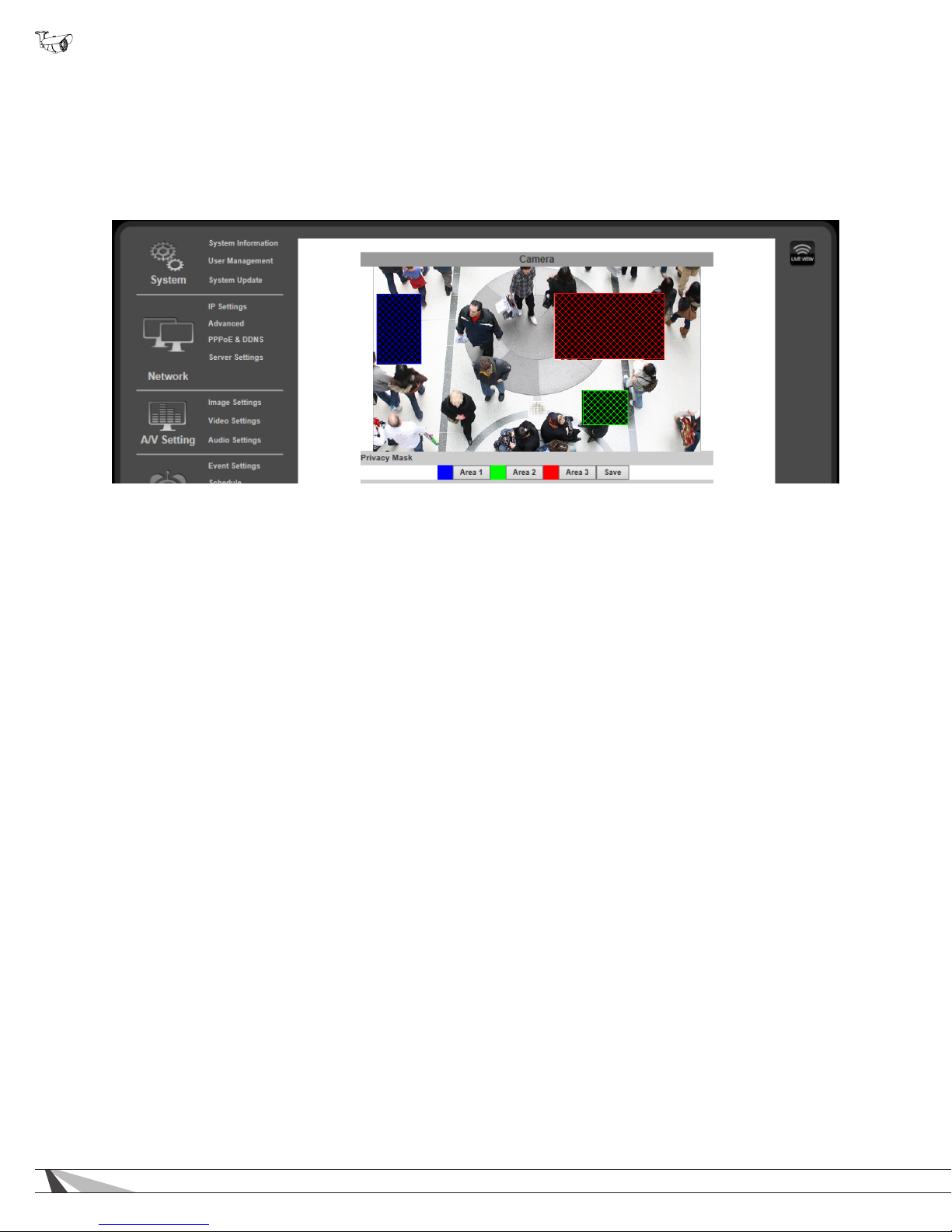
WPS-750-BUL-IPH Installation Manual
9.4.2.5. How to Congure Privacy Masks
Privacy mask allows for areas of an image to be blocked out to avoid unwanted capturing of sensitive areas.
Example: A camera used to monitor the front lawn of a house would have the windows on the neighboring homes masked to avoid
peeping on the neighbors.
• Menu Navigation: Log in as an administrator. From Home Screen, click “Cong” button in top right corner, then click “Image
Settings” in the left column menu.
A. Assigning a Privacy Mask
1. Select Area 1 next to the blue box.
2. Place the mouse at the upper left hand corner of the area to mask, hold down the left mouse button and drag the box over
the area to mask and release the mouse button. The area to be masked will be indicated by a colored grid.
3. Click Save to save the setting. The selected area will now display a black privacy mask under the colored grid, and this
area will be blacked out in all viewed and recorded video.
4. Repeat for areas 2 & 3 if multiple privacy masks are required.
B. Removing a Privacy Mask
1. Select the button for the area to remove. The colored grid for the selected area will be removed.
2. Select Save to save the change. The black privacy mask will be removed.
48
Page 49
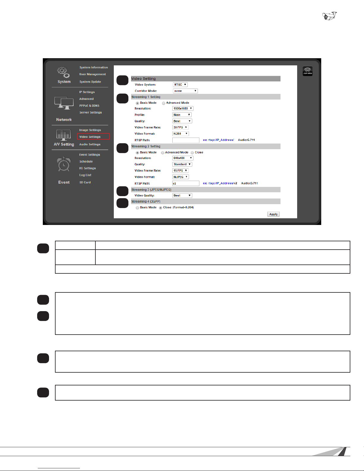
WPS-750-BUL-IPH Installation Manual
9.4.3. Video Settings Menu Overview
The Camera supports up to four streams that can be used for streaming to a mobile device, network recorder, control system GUI,
or the browser GUI simultaneously. While the highest quality is desired, it may not be supported by the network or device.
1
2
3
4
5
9.4.3.1. Video Setting (For BNC Test Adapter Output)
Video System Set the video system for the country of installation for PAL or NTSC. Default: NTSC
1
Corridor
Mode
Click “Apply” at the bottom right of the page to save modied settings.
9.4.3.2. Streaming 1 and 2 Setting
Streams 1 and 2 are used for most streaming connections, including the web browser view, NVR’s (uses both streams),
2
and mobile app access. Stream 1 is set to the best quality that can be used for the camera for the given application.
External factors like network trafc or a slow Internet connection limit the quality. Stream 2 can be set to output a
different stream type (H.264 or MJPEG) or to a lower quality setting. If a camera is accessed by a Wirepath™ NVR,
3
Stream 2 will be forced open so that recording takes place. See section for complete overview and setup of streaming
settings.
9.4.3.3. Streaming 3 (JPG/MJPEG)
Stream 3 only outputs MJPEG format, primarily for use in automation systems that allow live camera views through
4
touch panels. (Control4, Crestron, etc.) Frame Rate and Resolution settings are inherited from Stream 2. The
compression may be changed for faster streaming from slow networks.
Turn to “90” or “270” for a corrected aspect ratio if the camera is focused down a long hallway.
9.4.3.4. Streaming 4 (3GPP)
(3rd Generation Partnership Project) Streaming for older phones. Limited resolution and frame rate for devices with very
5
small amounts of memory or processor power.
© 2014 Wirepath Surveillance
49
Page 50
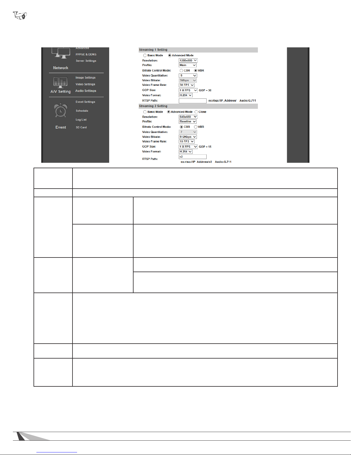
WPS-750-BUL-IPH Installation Manual
9.4.4. Video Streaming 1 and 2 Setup
Note: Streaming 1 and 2 settings are identical. Settings options have only been covered once.
Basic/
Advanced
Mode
Set the streaming mode to “Advanced” to allow ne control of streaming parameters. Extra options for Advanced
mode are indicated below.
Resolution 176x144 , 320x240, 640x480, 1280x720, 1920x1080 (default)
Main: This prole provides higher overall video quality and better video compression,
Main
which requires robust processing to decode in real-time. This prole should be used
in conjunction with a Wirepath NVR or in stand-alone applications when maximum
video quality is paramount.
Prole
Baseline: This prole provides slightly lower quality and less compression, making
it easier for less-robust processors to decode in real-time. This prole may provide
Baseline
benets in stand-alone applications without a Wirepath NVR, when camera will be
congured primarily for non-HD resolutions, or when remote or mobile device access
is a priority.
CBR – (Constant Bitrate) Bitrate of the image will remain constant regardless of
Bitrate
Control Mode
(Advanced Mode only)
image complexity. Provides a xed, known bandwidth use.
VBR – (Variable Bitrate) Bitrate of image increases and decreases based on image
complexity. A higher quality image can be transmitted but during complex scenes
bandwidth use increases.
Changes the range of VBR bitrate to Low or High.
• In “Basic” mode, settings range from Low (slowest) - Medium - Standard - High - Best (fastest).
Video
Quantitative
• In “Advanced” mode, quality may be set from 1 (slowest) to 9 (fastest).
When this setting is changed, Bitrate Control Mode automatically changes to VBR, and the bitrate will increase
or decrease depending on the select option.
This setting will change if the camera is enabled or modied from a Wirepath™ NVR, since the NVR
requires a CBR stream.
Video Bitrate
(Advanced Mode Only) Sets the xed bitrate to use when CBR is selected for bitrate control. The recommend
setting is 1, 2, 4, 6 or 8 Mbps for compatibility with Wirepath NVRs.
Adjusts the bitrate from 5 FPS to 30 FPS for streaming 1, and from 5 FPS to 15 FPS for Streaming 2. Higher
Video Frame
Rate
FPS (Frames Per Second) provides a smoother image but some display interfaces or devices may not be able
to support the higher rate.
Use the defaults 30 FPS (Streaming 1) and 15 FPS (Streaming 2) unless video display problems occur.
50
Page 51

WPS-750-BUL-IPH Installation Manual
Video Streaming 1 and 2 Setup, Continued
GOP (Group of Pictures) is used to generate the visible frames of a video stream. The GOP size setting
determines the multiplier to use for producing intermediate frames based on a standard of 15fps.
GOP Size
Video Format
RTSP Path Enter the name of RTSP (Real Time Streaming Protocol) path if RTSP has been congured.
Click “Apply” at the bottom right of the page to save modied settings.
Example: 1/2x FPS=7.5fps 1x FPS=15fps 2x FPS=30fps
Note: Changing this setting will affect the performance of the stream. The highest setting (2X FPS) may result in
saved video playback issues when Video Format is MPEG4 or MJPEG. We recommend that this setting is left at
the default setting.
While the default of H.264 is most efcient and will work in most cases; some devices that access Streaming 1
or Streaming 2 video streams may not support this format. For example, mobile devices, and automation system
GUIs sometimes do not support H.264. Adjust the format to suit the system requirements and intended use of
the streams.
Available Formats
• H.264
• MJPEG
© 2014 Wirepath Surveillance
51
Page 52
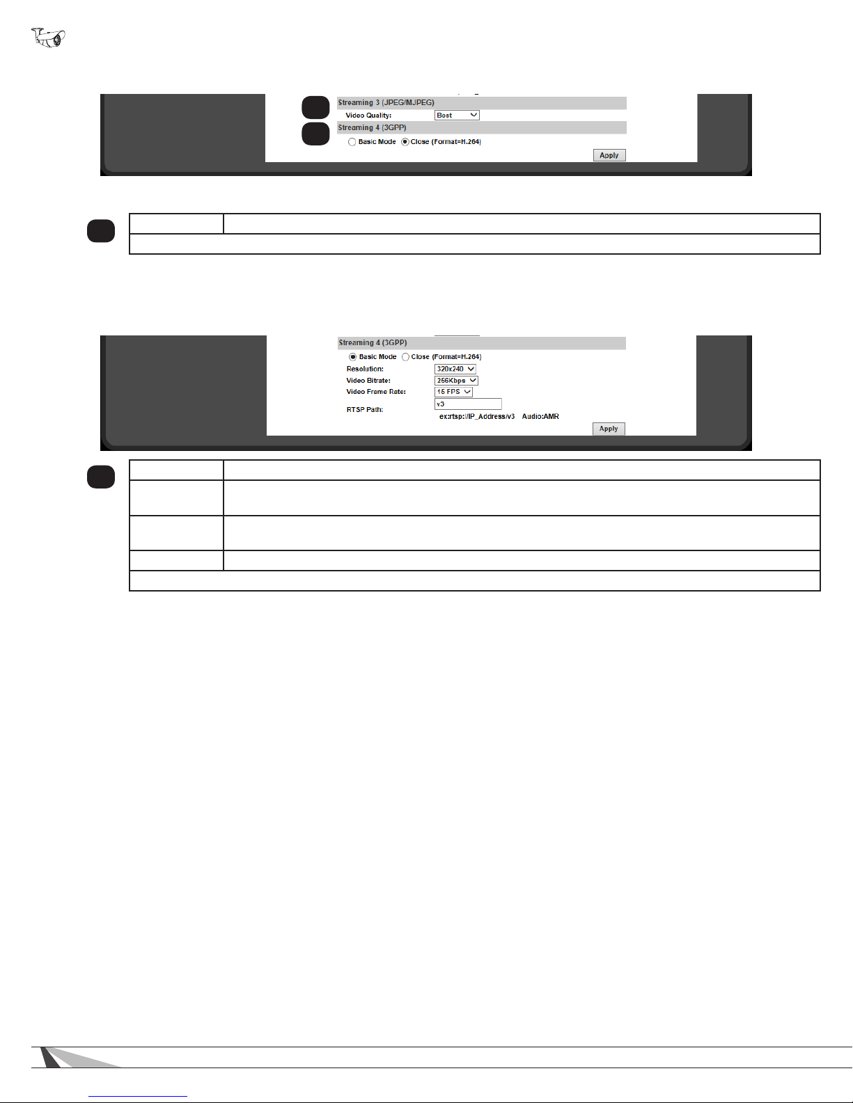
WPS-750-BUL-IPH Installation Manual
9.4.5. Streaming 3 and 4 Setup
1
2
9.4.5.1. Streaming 3
Video Quality Changes the video bitrate based on a level from Low (slowest) to Best (fastest).
1
Click “Apply” at the bottom right of the page to save modied settings.
9.4.5.2. Streaming 4
In “Close” mode, stream 4 defaults to h.264 only (settings will be inherited from Stream 2). Switch the setting to “Basic” mode to
access more settings:
Resolution Sets the resolution for Stream 4. Select from 176x144 (lowest), 320x240 (default), or 640x480 (best).
2
Video Bitrate
Video Frame
Rate
RTSP Path Enter the name of RTSP (Real Time Streaming Protocol) path if RTSP has been congured.
Click “Apply” at the bottom right of the page to save modied settings.
Set the constant bitrate for Stream 4. Settings range from 32 Kbps (minimum) to 1 Mbps (maximum).
Default: 256Kbps.
Set the frames-per-second (FPS) rate for Stream 4. Select from 5 to 30 FPS. Default: 15 FPS.
52
Page 53
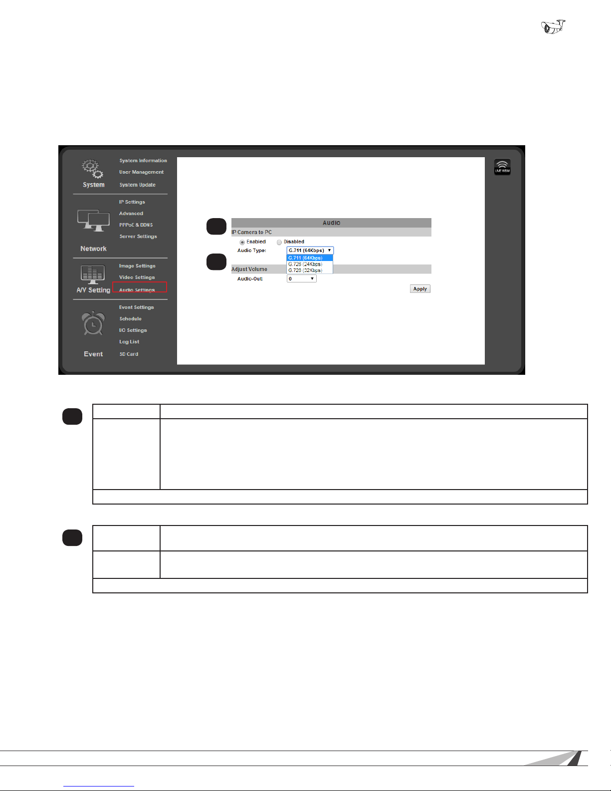
WPS-750-BUL-IPH Installation Manual
9.4.6. Audio Settings
The camera supports two-way audio recording and playback. Record audio at the camera location using an external microphone,
and hear it on PC’s or smartphones viewing the live feed or playing back recorded footage. Connect the camera’s audio output
to an audio/speaker system input and send audio from the web browser or smartphone interface (device must be equipped with a
microphone).
Some settings are not shown on the menu page by default since audio features are disabled (settings have been enabled
below).
1
2
9.4.6.1. IP Camera to PC
Enable/Disable
1
Audio Type
Click “Apply” at the bottom right of the Audio page to save modied settings.
Enable or disable audio features. Disabled by default.
Select the audio bit rate to use for streaming from the drop-down menu:
• G.711 (64Kbps)
• G.726 (24Kbps)
• G.726 (32Kbps)
Higher Kbps settings can increase audio quality but may cause audio to skip or cut-out on some
networks. Use the lowest Kbps setting that provides adequate audio quality.
9.4.6.2. Adjust Volume
Mic-In
2
Line-Out
Click “Apply” at the bottom right of the Audio page to save modied settings.
Volume level adjustment for the Microphone input to the camera. Acts as an input trim level adjustment.
Use the highest setting that does not cause distortion from the microphone.
Volume level adjustment for Line output from the camera. Acts as an output gain adjustment.
Use the lowest setting that will adequately drive an amplier input without distortion.
© 2014 Wirepath Surveillance
53
Page 54
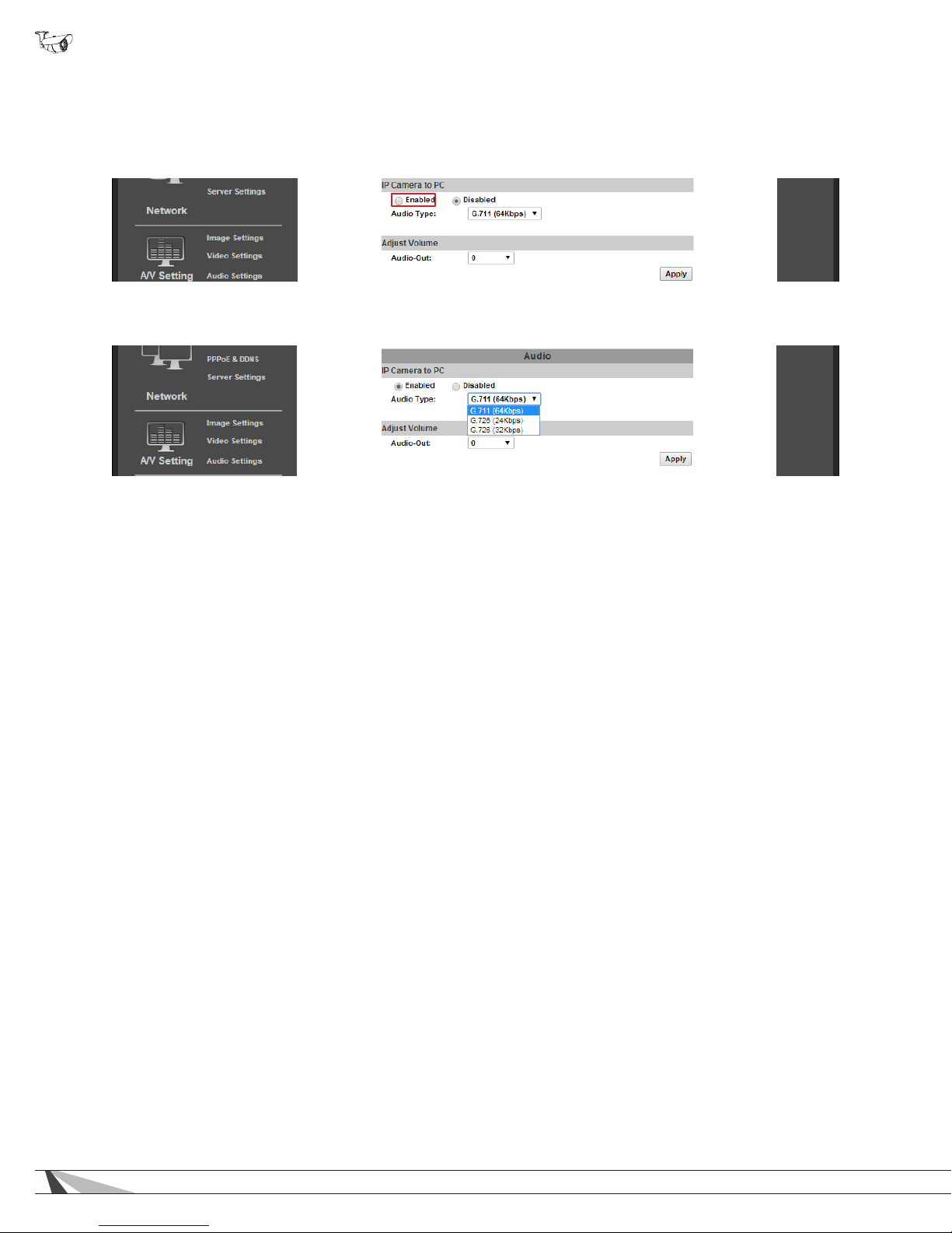
WPS-750-BUL-IPH Installation Manual
9.4.7. Camera Audio Technology Overview
9.4.7.1. How to Enable Audio Setup
Enable these settings ONLY if the features are being used, and only AFTER installation and connection of cameras and audio
equipment.
A. Click the Enabled button from the top left of the menu under “IP Camera to PC” in the gray bar.
B. Click Apply to reload the page with all settings enabled:
C. Change the settings as needed. Click Apply in the bottom right of the screen to save the new settings.
54
Page 55
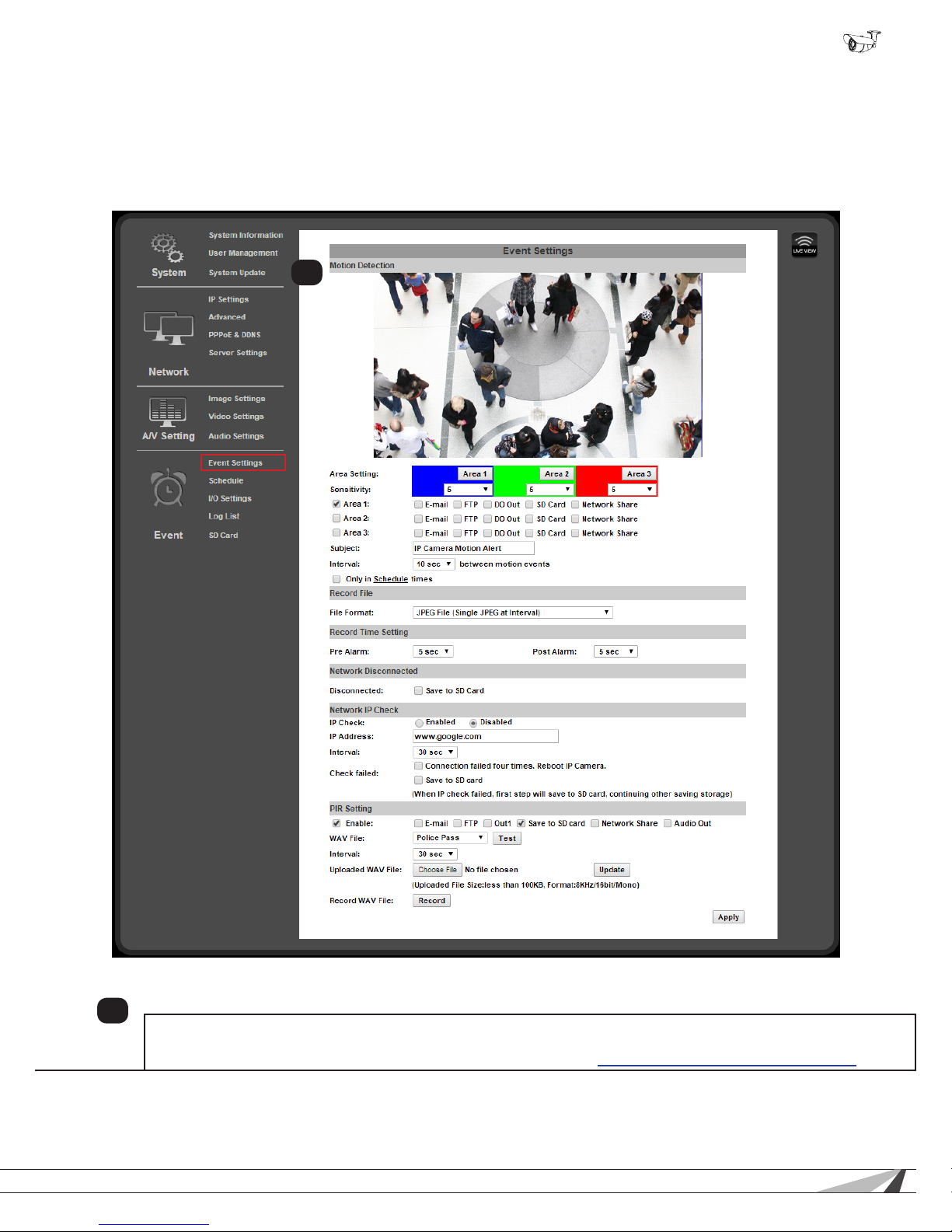
WPS-750-BUL-IPH Installation Manual
9.5. Event Record Setup and Scheduling
Cameras can be set up to record on a set schedule, or in response to contact closure, motion or tampering. Set up how and when
events are handled, including if and when to send an email notication or to send a le backup of an event to an off-site location.
The log lists detail all camera events including record triggers, logins and settings changes.
9.5.1. Event Settings Menu
1
Motion Detection
1
Up to 3 areas of a scene may be set up for detecting motion to trigger an action like recording video, taking a snapshot
or series of snapshots, and/or sending email notications to users. Detection may be may also be toggled on and off by
scheduling. Motion detection settings are detailed in a separate section: 9.5.2. Configuring Motion Detection Areas.
Continue to the next page for other menu descriptions.
© 2014 Wirepath Surveillance
55
Page 56
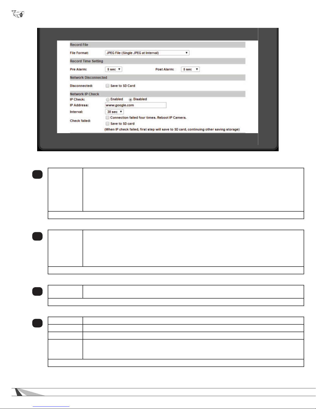
WPS-750-BUL-IPH Installation Manual
9.5.1.1. Record File
3
File Format
Click “Apply” at the bottom right of the page to save modied settings.
Selects the le type to create when the event occurs:
• AVI File – Creates a short .AVI format video le.
• JPEG Files (Streaming 1 must be set MJPEG) – Creates a series of JPEG les at about 1 FPS.
• JPEG File (Single JPEG at Interval) – Creates a single JPEG image le at time of event.
Note: JPEG Files (Streaming 1 Format must be MJPEG) saves or sends 10 JPEG images taken
approximately 1 second apart. Video Settings / Streaming 1 Format MUST be set to MPEG in order to
select this option.
9.5.1.2. Record Time Setting
4
Pre/Post
Alarm
Click “Apply” at the bottom right of the page to save modied settings.
Pre Alarm – Amount of time prior to the event to start the recording, from 0-5 seconds.
Post Alarm – Amount of time after to the event to stop the recording, from 0-10 seconds.
Note: The camera cannot record intervals for motion events longer than 15 seconds in one video clip.
Multiple recordings will be saved for motion events longer than the time set Motion Detection “Interval”
section. In such cases there may be a gap of several seconds between recordings.
9.5.1.3. Network Disconnected
Disconnected
5
Click “Apply” at the bottom right of the page to save modied settings.
When checked, the camera will record event video to the microSD card (if installed) when the camera
loses network connection.
9.5.1.4. Network IP Check
IP Check When enabled, the Camera will periodically ping the address entered into the IP Address box below.
6
IP Address Enter an IP Address or website URL to ping for checking connectivity.
Interval Select the time between pings to the entered IP Address or URL.
Check “Connection failed four times...” to enable auto rebooting if the IP address does not respond after
Check Failed
Click “Apply” at the bottom right of the page to save modied settings.
four attempts.
Check “Save to SD Card” to save a log le to the microSD Card when the IP Address does not respond.
56
Page 57
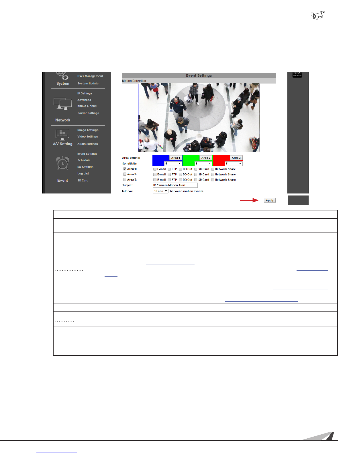
WPS-750-BUL-IPH Installation Manual
9.5.2. Conguring Motion Detection Areas
Motion detection allows for specic areas of the image to be used for triggering the recording of video, an alarm, or sending a
notication. When an area is dened, motion in that area will trigger the predened action; this is useful to avoid unwanted events
from being triggered due to motion in areas of no concern.
9.5.2.1. Motion Detection Settings Overview
(Appears at bottom corner of page,
moved up for reference)
Area Setting Area Setting Select the button to set the area for detection.
Sensitivity
Adjustable from 1 (Requires higher amount of motion to trigger) to 10 (Requires low amount of motion
to trigger).
• Area # - when selected the area is enabled allowing for the events dened below to occur.
• E-Mail - check the box to send media via email. Requires conguration of Email Settings as
dened in section 9.3.8.2. Mail Settings.
• FTP - check the box to save media to an FTP site or server. Requires conguration of FTP as
dened in section 9.3.8.3. FTP Settings.
Area 1, 2, 3
• SD Card - check the box to save media to a microSD card (if installed). See section 9.7. SD Card
Menu for more information about microSD card setup and use.
• DO Out – Check to activate the DO contact output to trigger a connected device contact input.
Requires connection and conguration of DO output as dened in section 7.3. Relay Connections.
• Network Share – check the box to save media to a Network Share location. Requires the
conguration of Network Share as dened in section 9.3.8.4. Network Share Settings.
Subject Text to use as subject of email notications when they are sent.
Interval
Selects the minimum time between motion events that the camera will respond to. Higher values are
useful to reduce notications for camera scenes with more expected motion.
Only in
Schedule
When selected, motion events will only be triggered based on a congured schedule.
Times
Click “Apply” at the bottom right of the page to save modied settings.
© 2014 Wirepath Surveillance
57
Page 58
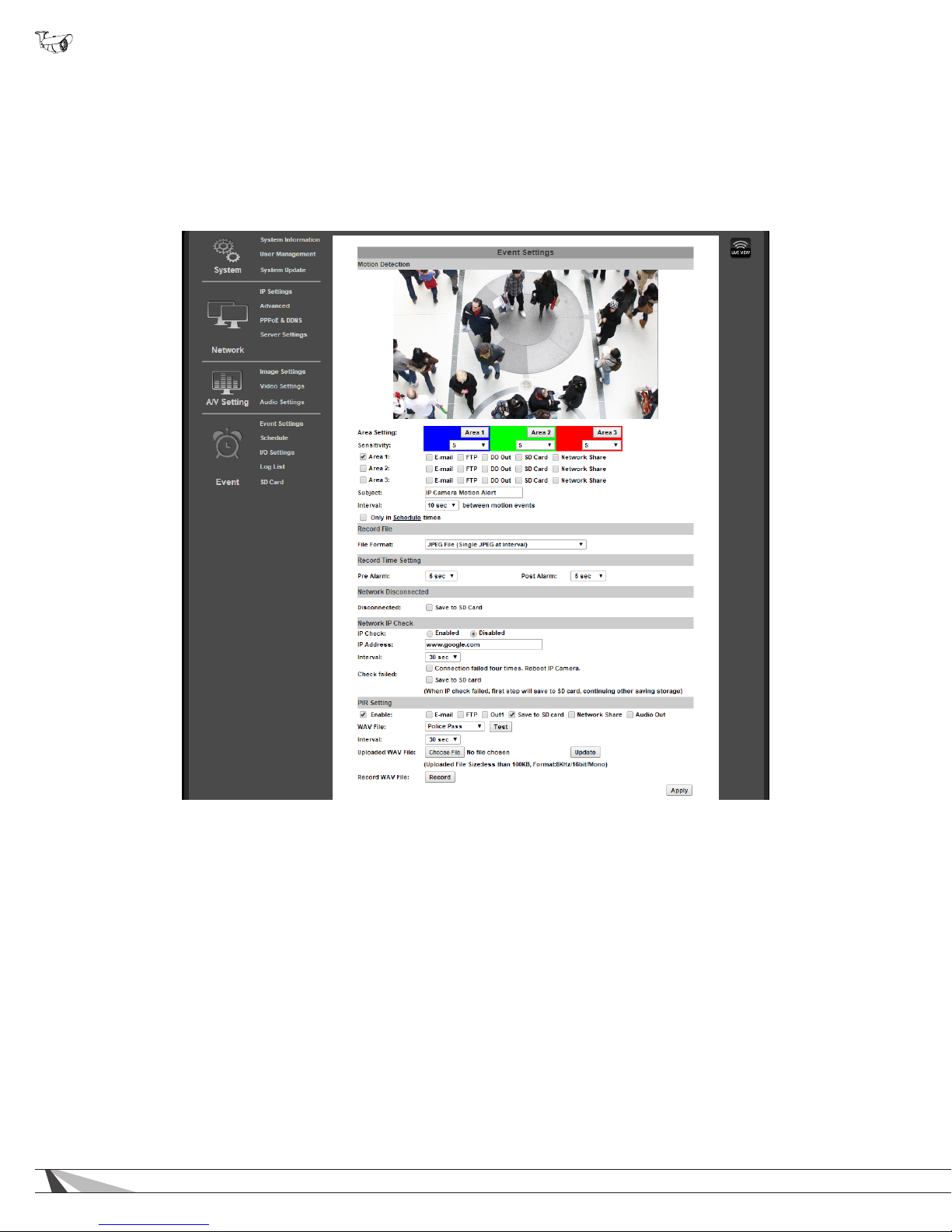
WPS-750-BUL-IPH Installation Manual
9.5.2.2. Adding a New Motion Detection Area
A. Select Event Setting under Event on the left side Menu.
B. Select the Area for Motion Detection.
C. Select Area 1 next to the blue box.
D. Place the mouse at the upper left hand corner of the area to mask, hold down the left mouse button and drag the box over the
area to mask and release the mouse button.
E. Select the Sensitivity level in the drop down box under the Area. (Range 1 Low to 10 High).
F. Select the check box next to the area and select the type of Events to perform when motion is detected in that area.
G. Select a Name to use for the Subject line of email notications.
H. Set the Interval between motion events (the minimum time to wait before triggering subsequent motion events).
I. Repeat Steps A-H for Areas 2 & 3 if more areas are needed.
J. Set the Delivery Media Format.
K. Select the File Format from the dropdown list.
L. Select the time to Start and Stop the recording.
M. Select Action to Perform when Connection is Lost.
N. Select Apply at the bottom of the screen to save the settings.
9.5.2.3. Removing a Motion Detection Area
A. Select the button for the area to remove. The colored grid for the selected area will be removed.
B. Click “Save” to save the change.
58
Page 59
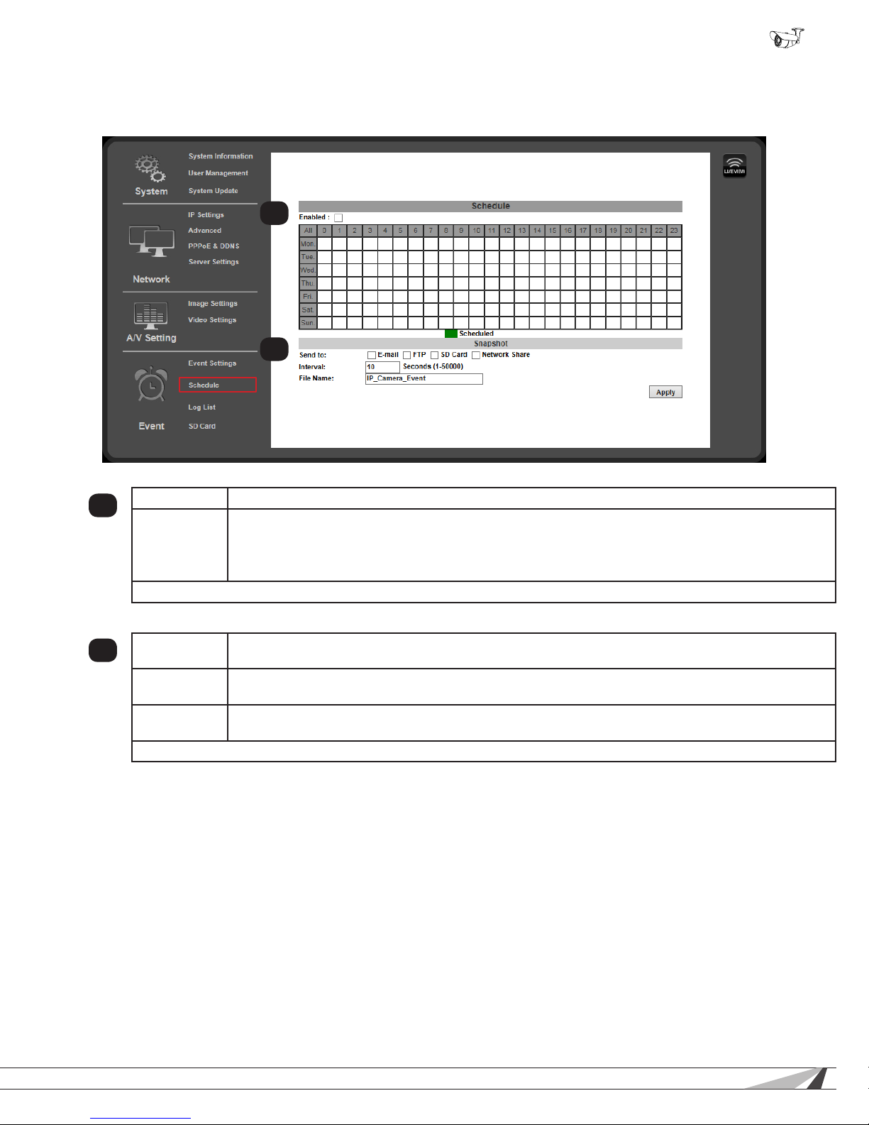
9.5.3. Schedule Menu
Use this menu to congure a schedule for capturing images from the camera to be stored.
1
2
WPS-750-BUL-IPH Installation Manual
Enable Check box to Enable Scheduling feature.
1
Schedule
Click “Apply” at the bottom right of the page to save modied settings.
Grid with Days of the Week and Time of day for snapshots to be recorded. Enabled dates and time
appear as a Green box.
NOTE: This Schedule can also act to provide days/times when motion Events are allowed to send
notications and send or save media. See Only in Schedule times in section .
9.5.3.1. Snapshot Menu
Send To
2
Interval
File Name
Click “Apply” at the bottom right of the page to save modied settings.
Select the method used to send or save JPEG snapshots based on the schedule dened above.
Available options include Email, FTP, SD Card and Network Share.
Sets the interval between the snapshots for the scheduled day. Example: when set to 60 seconds, a
snapshot will be sent or saved every 60 seconds.
Enter a name to use to identify the snapshot les. Use this menu to congure the Cameras Contact &
Relay connections.
© 2014 Wirepath Surveillance
59
Page 60
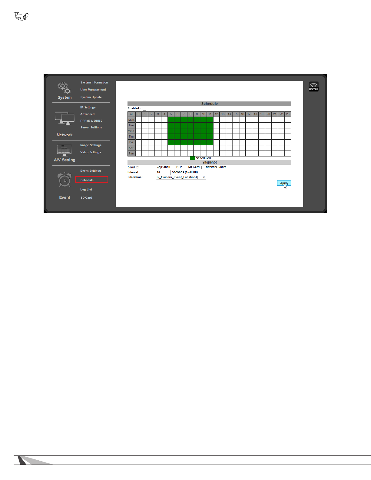
WPS-750-BUL-IPH Installation Manual
9.5.3.2. How to Set Up Scheduling for Events
A. Select Schedule under Event on the left side Menu.
B. Select the Enabled check box.
C. Click on the box(es) to enable one-hour blocks of time for the desired Day of week and Time of day.
9.5.3.3. Set up Snapshot
A. In the Snapshot section, select the delivery method for the Snapshot.
B. Select an Interval between the Snapshots for the selected periods.
Example: when set to 60 seconds, a snapshot will be sent to the selected destinations every 60 seconds.
C. Select a Filename to identify the Snapshot.
D. Select Apply at the bottom of the screen to save the settings.
60
Page 61
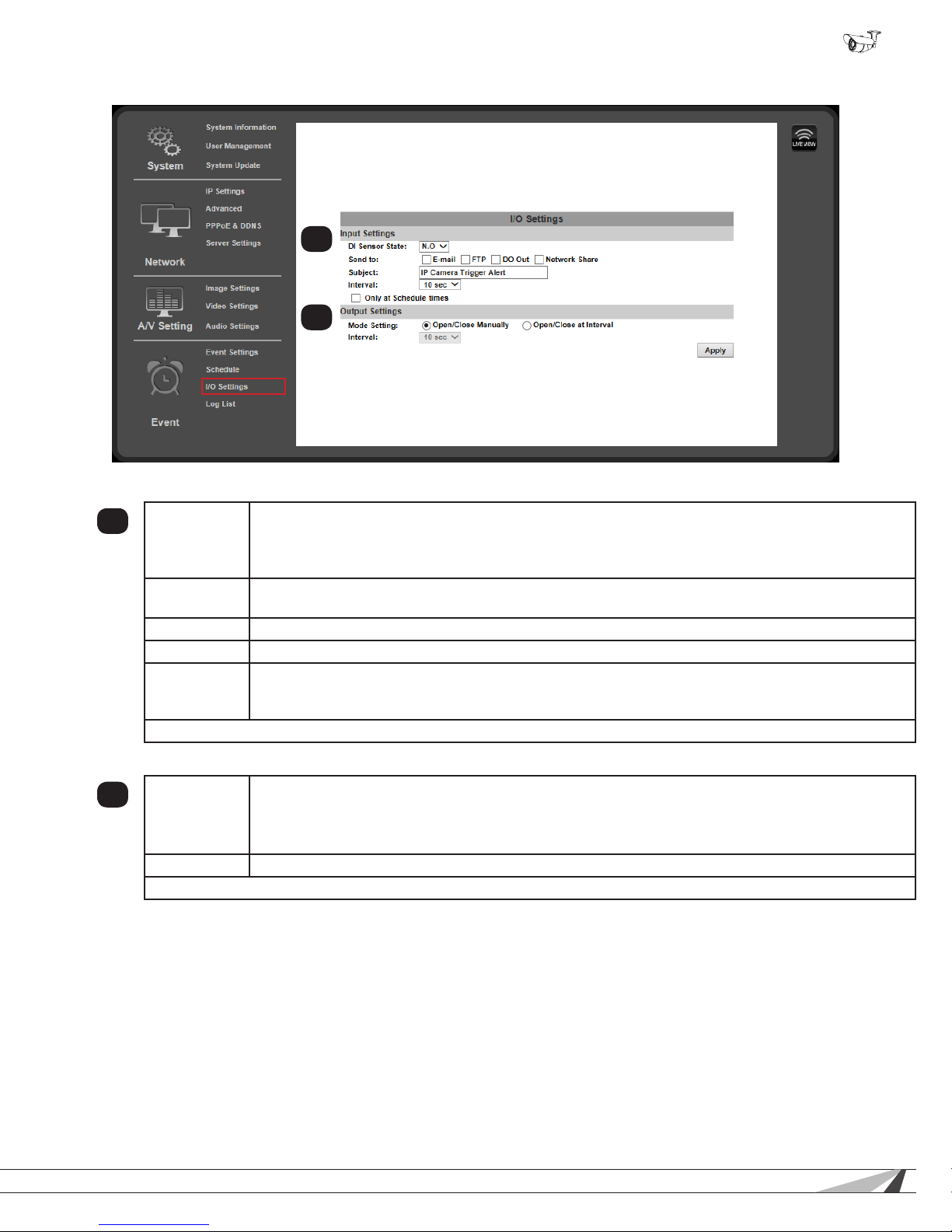
9.5.4. I/O Settings
9.5.4.1. Input Settings
1
DI Sensor
State
Send To
Subject Enter a name to use to identify the event.
Interval Select the time to wait between input events before another event can be triggered.
Only at
Schedule
Times
Click “Apply” at the bottom right of the I/O Settings page to save modied settings.
WPS-750-BUL-IPH Installation Manual
1
2
N.O Camera expects contact closure connected to the DI input to be normally Open. Event is triggered
when the contact is closed.
N.C Camera expects contact closure connected to the DI input to be normally Closed. Event is
triggered when the contact is open.
If notication or logging is desired, select the destination to send it to when the DI input event is
triggered.
When selected, events will only be monitored based on a congured schedule. Scheduling must be
enabled for this feature to work.
9.5.4.2. Output Settings
2
Mode Setting
Interval Select the interval between DO output Open and Close when Mode Setting is “Open/Close at Interval”.
Click “Apply” at the bottom right of the I/O Settings page to save modied settings.
© 2014 Wirepath Surveillance
Open/Close Manually Device connected to the DO output can be triggered from the browser GUI or
congured Events only.
Open/Close at Interval DO output will be cycled between Open and Closed at the Interval congured
below.
61
Page 62
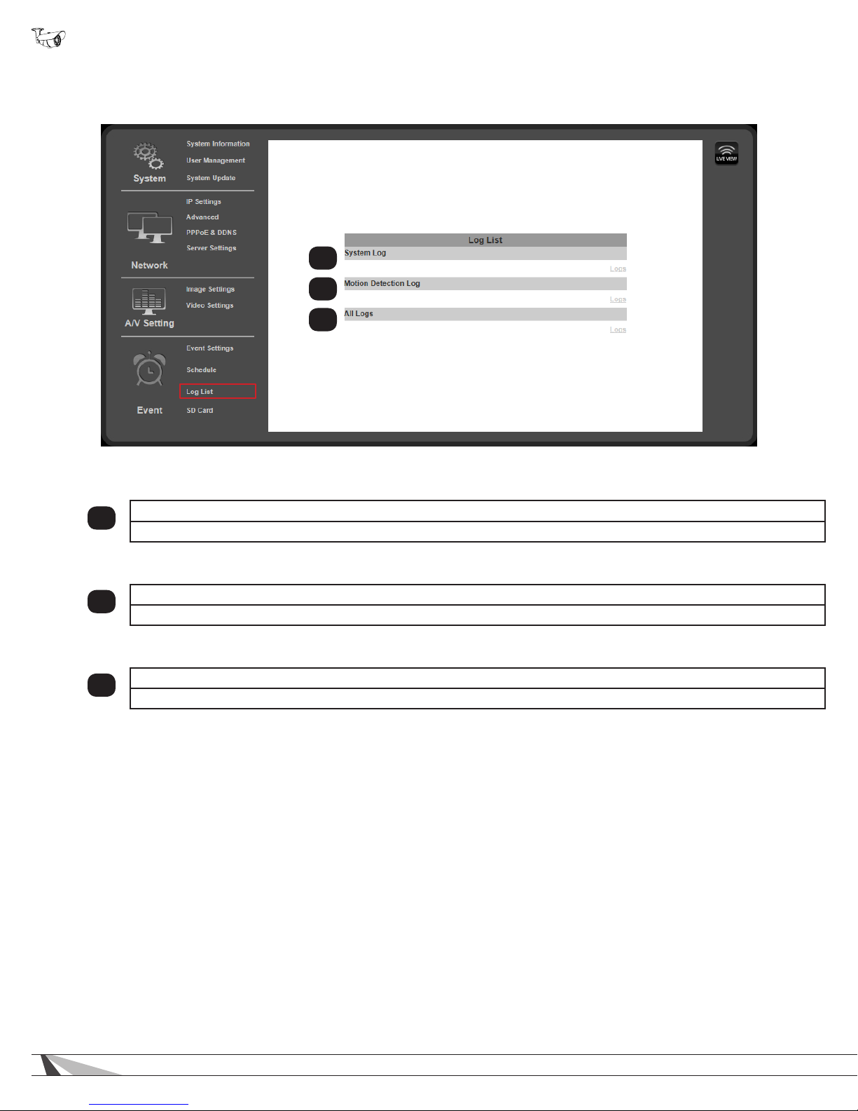
WPS-750-BUL-IPH Installation Manual
9.6. Log List
The camera software stores a log le for several parameters in the camera. Use the Log List menu to select a log to view.
1
2
3
Displays System events such as logins and conguration changes. This log is maintained even through loss of power.
1
Click “Logs” to open and view the log le in a new browser window.
9.6.4.1. Motion Detection Log
Displays Motion Detection events. This log is NOT maintained when power is lost.
2
Click “Logs” to open and view the log le in a new browser window.
9.6.4.2. All Logs
Displays a list of all log entries from the three individual logs.
3
Click “Logs” to open and view the log le in a new browser window.
System Log
62
Page 63
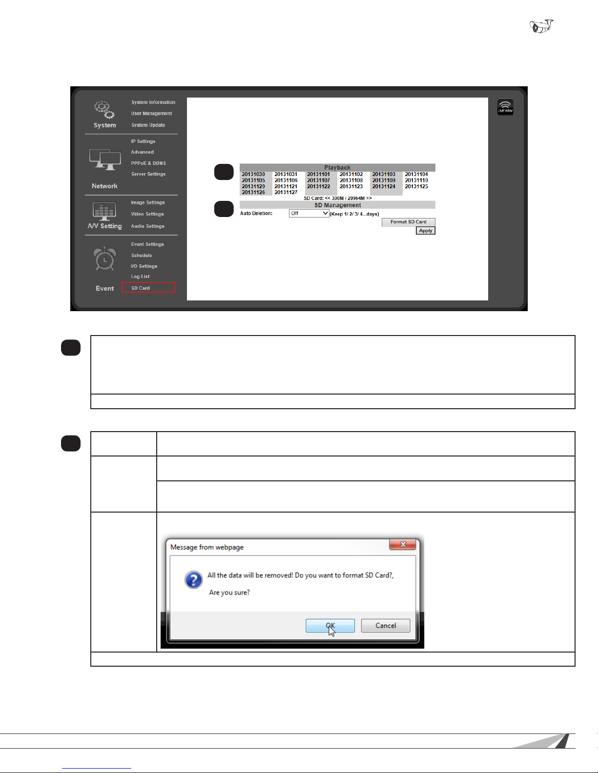
9.7. SD Card Menu
Use this menu to set up and access a microSD card.
1
2
WPS-750-BUL-IPH Installation Manual
9.7.1. Playback
This area will display “No SD Card” when no microSD card is installed. When a compatible card is installed and the card
1
contains media, folder names are displayed using the dates when media was saved as titles. Selecting a folder name
displays the folder contents. File names are displayed in gray. If there are more than 10 les, additional pages can be
selected below the le list.
Right clicking a le name allows the le to be Saved or Saved As to your PC.
“SD Card:” displays the total size and available space of the installed microSD card.
9.7.2. SD Management
Auto Deletion
2
Interval
Format SD
Card
Select the method used to send or save JPEG snapshots based on the schedule dened above.
Available options include Email, FTP, SD Card and Network Share.
Off - No data on the SD Card will be deleted by the camera. If the microSD card becomes full, no further
data can be recorded.
1st to 30th Day Set the number of days worth of footage to keep on the memory card.
Data older than the selected number of days will be deleted.
Click to format the SD card, then click “OK” in the dialog box that appears:
Click “Apply” at the bottom right of the page to save modied settings.
© 2014 Wirepath Surveillance
63
Page 64

WPS-750-BUL-IPH Installation Manual
10. Internal Heater Overview
This IP camera is equipped with an internal heating element that is programmed to turn on as needed based on ambient
temperature. If temperatures fall below 23°F for an extended period, the internal heater will turn on to keep the iris operating
correctly. Without this feature, the iris could become so cold that it sticks in place, causing the camera to lose picture. Once
temperatures rise back above 59°F, the heater will turn off to save power.
Temperature Operating Behavior
23°F (-5°C) or lower Heater will turn on to protect camera
-40°F (-40°C) or lower Camera should be powered off to protect internals. Keep the camera off until temperature rises to a
safe range.
59°F (15°C)-113°F (45°C) Heater will turn back off.
Over 113°F (45°C) Camera should be powered off to protect internals. Keep the camera off until temperature falls to a
safe range.
10.1. Safe Operating Range
• -40°F ~ 113°F (-20°C ~ 45°C)
• If the ambient temperature is between these temperatures, the camera should power up and operate normally.
• If temperatures remain above or below the safe operating range, the camera will shut off or will not power on to
avoid damage to the internals.
64
Page 65
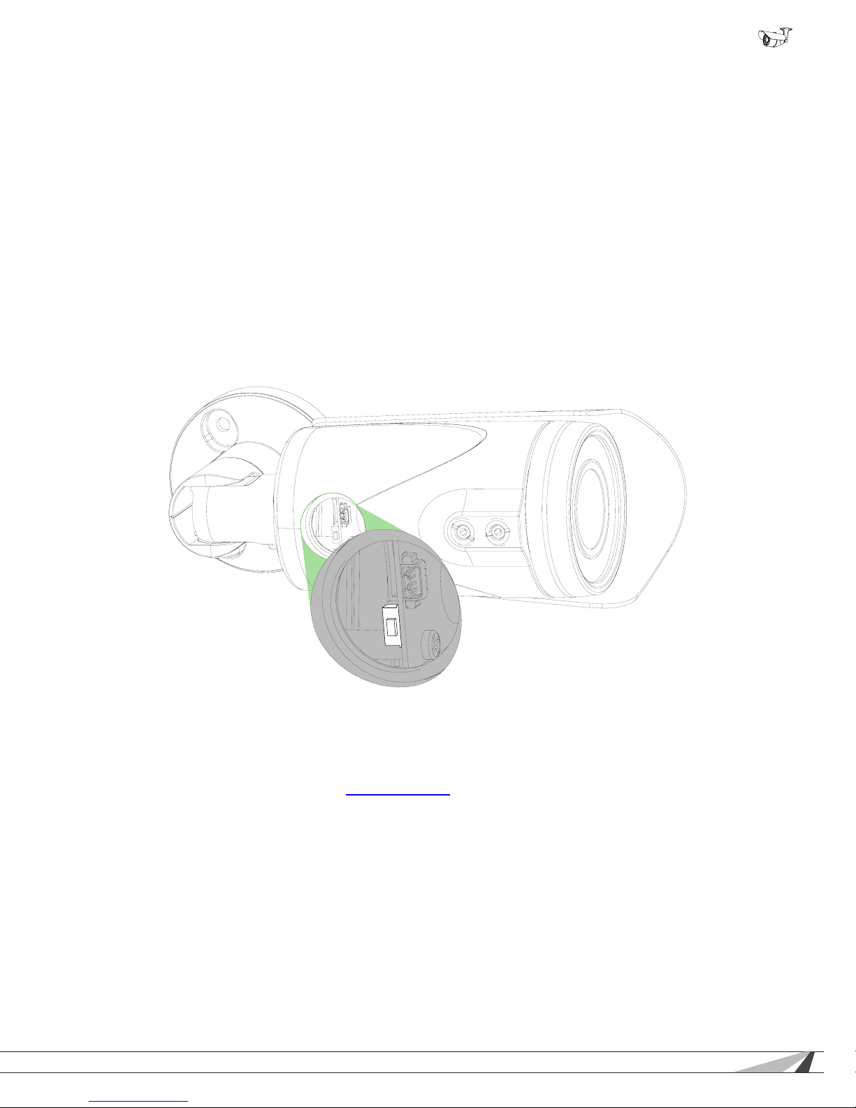
WPS-750-BUL-IPH Installation Manual
11. Reset Procedure
If the camera ever becomes unresponsive after an update, or Administrator access is lost, it may be necessary to manually reset
the camera back to default conguration. The procedure was designed to require signicant effort so that resets could not easily be
done with malicious intent. For this reason, it may be necessary to remove the camera to do the reset unless an assistant can help.
Warning! Resetting the camera erases ALL settings, including IP and user/admin settings. Use the IP Installer
software to rediscover the camera on the network after the reset. The IP address will return to DHCP.
Important! You must have direct access to the camera and its power source to reset the rmware. Have a way
of reaching the camera. Have an assistant to help control power, or remove the camera to perform the reset.
A. Remove power to the camera at the power supply location or by disconnecting the network cable from the network (if using
PoE power).
B. Open the camera cap and rotate the gimbal so the small black momentary switch on the board is accessible:
C. To perform the reset, the button must be pressed and held for 30 seconds while power is applied. The button must remain
pressed for the entire 30 seconds.
D. After 30 seconds, release the button. The camera will boot up as normal and can be discovered on the network again using the
IP Installer software.
12. Mobile App Access
Use your computer, or FREE iPhone®, native iPad®, or Android® smartphone apps to view cameras while at the ofce or on the go.
Details on setup and operation can be found at www.SnapAV.com.
© 2014 Wirepath Surveillance
65
Page 66

WPS-750-BUL-IPH Installation Manual
13. Specications
Imaging
Image sensor 1/2.7” 2MP CMOS sensor
Lens Type Vari-focal 3~10.5mm Mega Pixel Lens F1.4
View Angle 103.73°(H) 54.43°(V)
Video Resolution 1920x1080@30fps, 1280x720@30fps, 640x480@30fps, 320x240@30fps,
176x144@30fps
Minimum Illumination 0.05 lux @F1.4 (IR off)
0 lux @F1.4 (IR on)
DC IRIS Yes
Shutter Speed 1/5~1/1000
True Day/ Night (IR Cut Filter) Yes
IR Distance- 65 ft
Digital WDR Ye s
DNR Yes
Sense Up Yes
AGC Yes
Lens Distortion Correction Ye s
Anti-Fog Yes
Input/Output Ports
Video Test Port Yes
Setup Power Port Yes
On Pigtail 1 Digital in and 1 Digital out (3pin Green Socket), DC-jack, 1 Audio in and 1
Audio out, male RJ45
Audio
Audio Compression G.711(64K) and G.726(32K,24K) audio compression
Audio Input 3.5mm x 1
Audio Output 3.5mm x 1
Network
Ethernet 10/100 Base-T
Network Protocol HTTP, HTTPS, SNMP, QoS/DSCP, Access list, RTSP, TCP/ IP, UDP, SMTP,
FTP, PPPoE, DHCP, DDNS, NTP, UPnP, 3GPP, SAMBA, Bonjour
Technology
Video Adjust Brightness, Contrast, Hue, Saturation, Sharpness, Shutter Speed adjustable,
AGC, Sense-Up, D-WDR, Flip, Mirror, Noise reduction, Day&Night adjustable
Quad Streaming Yes
Image snapshot Yes
Full screen monitoring Yes
Privacy Mask Yes
Compression format H.264/ M-JPEG
Video bitrates Constant (CBR), and Variable (VBR)
Motion Detection Ye s
Actions upon Triggers Email
FTP
Save to micro SD card
SAMBA
Digital Output
Pre/ Post alarm Yes
66
Page 67

WPS-750-BUL-IPH Installation Manual
Security and QoS Password protection, IP address ltering, HTTPS encrypted data transmission,
QoS/DSCP
Simultaneous Connections / Users Up to 10
SD Card Management Yes
Recording Triggers Motion Detection
IP Ping failure
Network disconnect
Schedule
Digital Input
Video Format AVI, JPEG
Video Playback Yes
Housing & Power
Operating Temperature -40 to 113°F
Weight 1.98 lbs
Weather Rating IP66
POE / Consumption Yes - PoE IEEE 802.3af
IEEE 802.3af
80mA 3.83W(IR off Heater off)
110mA 5.28W(IR on Heater off)
140mA 6.72W(IR off Heater on)
170mA 8.16W(IR on Heater on)
12VDC Power Consumption 230mA 2.76W(IR off Heater off)
380mA 4.56W(IR on Heater off)
470mA 5.64W(IR off Heater on)
600mA 7.20W(IR on Heater on)
Certications
Onvif Yes
CE, FCC, RoHS Ye s
Client System Requirements
OS Windows 7, Microsoft IE 11.0 or above
Mobile Support iOS 4.3 or above, Android 2.3 or above
Suggested Hardware Intel Dual Core 2.53G,RAM: 1024MB, Graphic card: 128MB
Minimum Hardware Intel-C 2.8G, RAM: 512MB, Graphic card: 64MB
© 2014 Wirepath Surveillance
67
Page 68
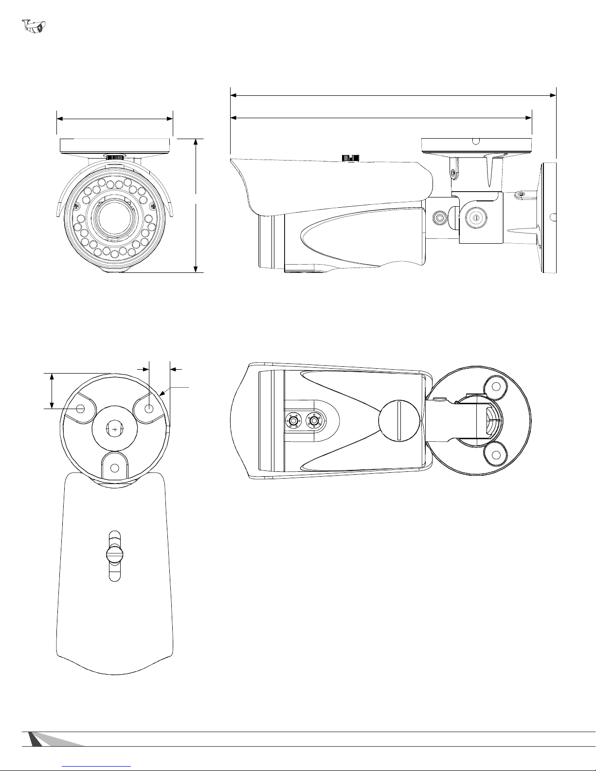
WPS-750-BUL-IPH Installation Manual
14. Dimensions
9.07in.
3.24in.
3.73in.
0.6in.
1in.
Ø 3.06in.
8.39in.
68
Page 69
WPS-750-BUL-IPH Installation Manual
15. Warranty
3-Year Limited Warranty
This Camera has a 3-Year Limited Warranty. The warranty includes parts and labor repairs on all components found to be defective
in material or workmanship under normal conditions of use. This warranty shall not apply to products that have been abused,
modied, disassembled, or improperly installed. Products to be repaired under this warranty must be returned to Wirepath™
Surveillance or a designated service center with prior notication and an assigned return authorization number (RA).
16. Contacting Technical Support
Phone Number (866) 838-5052
Email [email protected]
© 2014 Wirepath Surveillance
69
Page 70
© 2014 Wirepath™ Surveillance
140826-1350
 Loading...