

Page 1
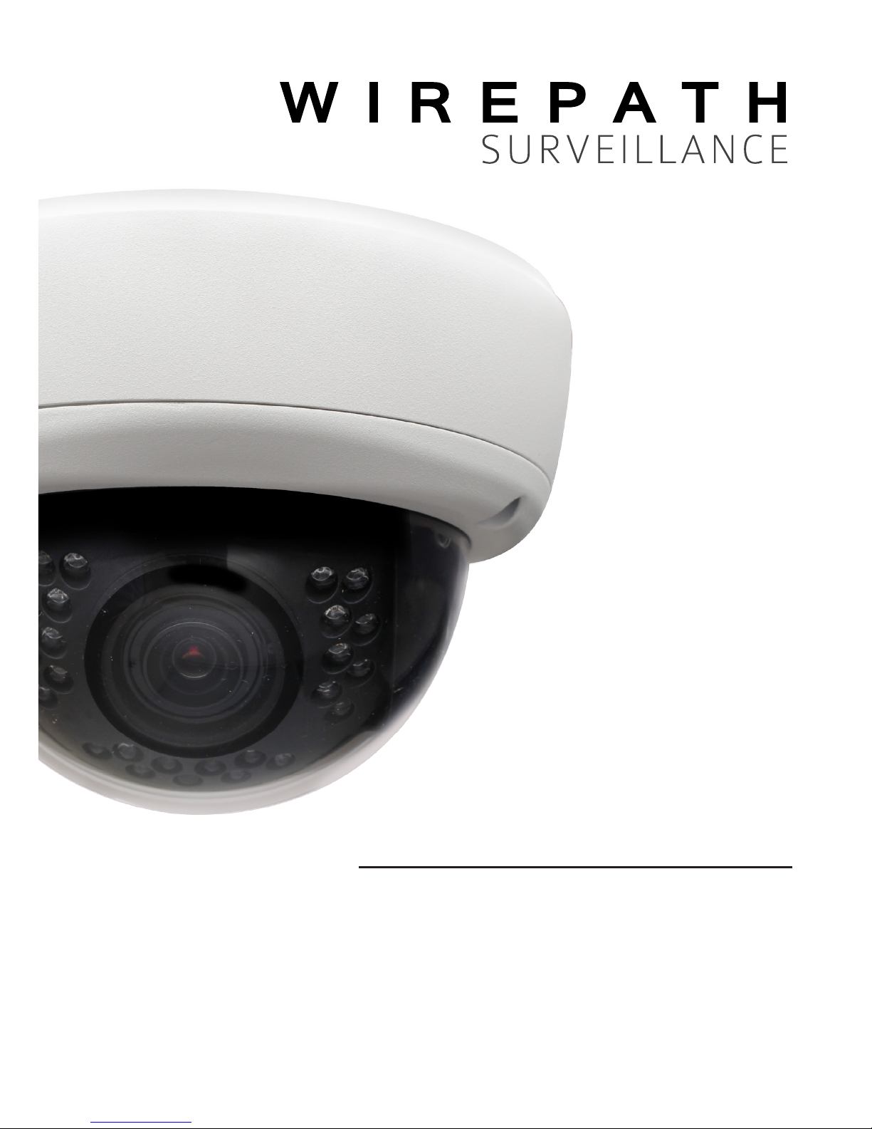
CAMERA
DOME
INSTALLATION MANUAL
Review manual thoroughly before installation.
Retain for future reference.
WPS-565-DOM-A
Page 2
2
WPS-565-DOM-A Installation Manual
Safety Instructions
This information is provided to ensure your safety and to prevent
physical or nancial loss. Please read this document carefully before installing and
operating the camera.
1. Handle with care.
Use caution when handling to avoid damage to sensitive internal
components.
2. Do not install camera under extreme temperatures.
This camera only operates under temperature conditions between 14˚F ~
140˚F.
3. Do not mount the camera directly facing bright light sources.
Exposing the camera to strong light over long periods of time will
damage the camera’s sensor.
4. Do not supply voltage other than 12V DC or 24V AC.
This camera regulates power within this range. Higher voltages will
damage the camera’s electronic components.
5. Do not install camera in environments with extreme humidity.
Installing camera in environments with extreme humidity may cause
moisture to condense on the surface of the lens or dome cover,
which can affect picture quality.
Page 3

WPS-565-DOM-A Installation Manual
3
© 2014 Wirepath Surveillance
Table of Contents
1. Features 5
2. Package Contents 6
3. Wiring Recommendations 7
3.1. Wiring Connections 7
4. Installation Instructions 8
5. Camera Operation Setup 10
5.1. Focus, Zoom and Position 10
5.2. Using the Test Adapter 10
6. OSD SETUP Menu 11
6.1. Default Settings Description 11
6.2. How to Navigate the OSD SETUP Menu 12
6.2.1. OSD Joystick (Test Adapter) 12
6.2.2. How to Save Settings 12
6.3. OSD Menu Structure Outline 13
6.4. OSD MENU SETTINGS 15
6.4.1. LENS Menu 15
6.4.1.1. DC Mode 15
6.4.1.2. MANUAL Mode 15
6.4.2. EXPOSURE Menu 16
6.4.2.1. SHUTTER 16
6.4.2.2. AGC (Auto Gain Control) 16
6.4.2.3. DWDR(Digital Wide Dynamic Range) 16
6.4.3. WHITE BALANCE Menu 17
6.4.3.1. Auto Modes 17
6.4.3.2. AWCSET Mode 17
6.4.3.3. WB MANUAL Setting Mode 17
6.4.4. BACKLIGHT Menu 18
6.4.4.1. BLC (Back Light Compensation) Setup 18
6.4.4.2. HLC (High Light Compensation) Setup 18
6.4.5. DAY & NIGHT Menu 19
6.4.5.1. D&N EXT (External Sensor) 19
6.4.5.2. D&N COLOR Mode 19
6.4.5.3. B/W Setting 19
6.4.5.4. D&N AUTO Setting 19
Page 4
4
WPS-565-DOM-A Installation Manual
6.4.6. DPC (Dead Pixel Compensation) 20
6.4.7. SPECIAL Menus 21
6.4.7.1. CAM TITLE Setting 21
6.4.7.2. MOTION Detection 21
6.4.7.3. PRIVACY Setting 22
6.4.7.4. PARK LINE Setting 22
6.4.7.5. IMAGE ADJ. Setting 23
6.4.7.6. COMM ADJ. — RS485 Setup 24
6.4.8. Exit Menu — Save and Reset 24
6.4.8.1. SAVE 24
6.4.8.2. NOT SAVE 24
6.4.8.3. RESET 24
7. Troubleshooting 25
8. Specications 26
9. Dimensions 27
10. 5-Year Limited Warranty 27
11. Contacting Technical Support 27
Page 5

WPS-565-DOM-A Installation Manual
5
© 2014 Wirepath Surveillance
1. Features
1/3” 960H Sony Super-HAD II CCD
The Sony Super HAD II CCD is ideal for low lux illumination, resulting in a clear and
crisp image.
Varifocal Auto-Iris Lens
This camera features a varifocal lens with a focal length of 2.8-12 mm. The autoiris function intuitively manages the amount of light passing through the lens for
consistent image brightness.
DWDR (Digital Wide Dynamic Range)
Digital Wide Dynamic Range is ideal for high contrast environments, improving
the contrast between very dark and very bright areas in a scene, and producing
a more balanced image.
2D Digital Noise Reduction
Digital noise reduction produces clear images in low light conditions. Not only
does it help to reduce image noise, but it also minimizes burring of objects
in motion, producing extremely clear picture quality — even under low-light
conditions.
RS-485 Connection and OSD
This camera features an OSD (on-screen display) for initial setup and settings
adjustment. Remote control is possible using a compatible DVR or PTZ controller
connected to the camera’s RS485 wire leads.
Weatherproof Housing
The IP66-rated weatherproof housing makes this camera ideal for outdoor
surveillance.
Video Test Port
Adjust angle, zoom, and focus at the camera for fast and easy installation.
Page 6

6
WPS-565-DOM-A Installation Manual
2. Package Contents
(1) WPS-565-DOM-A Camera
(1) WPS-ACC-PWR-M AC/DC Power Plug
(1) OSD Joystick / BNC Test Adapter
(4) Surface Mounting Screws (includes 1 spare)
(4) Wall Anchors (includes 1 spare)
(1) 3mm Allen key
(1) Foam gasket
(1) Paper mounting template
(1) Installation Manual
(1) Spare Silica packet in vacuum sealed bag
NOTE: A POWER SUPPLY IS NOT INCLUDED WITH THIS CAMERA.
The PS-12DC-1A or WPS-PS multiple output power supplies are recommended.
NOTE 2: A SILICA DESICCANT PACK IS MOUNTED INSIDE THE DOME HOUSING.
This package should remain inside the housing after installation, even when
adding additional desiccant packs.
Page 7
WPS-565-DOM-A Installation Manual
7
© 2014 Wirepath Surveillance
3. Wiring Recommendations
Wiring should be installed, terminated, and tested for connectivity before the
camera is installed. Specications for each connection are detailed below.
3.1. Wiring Connections
1. Power (Required)
It is recommended to install the camera power supply near the recording
location and run a remote power wire to the camera. Use the voltage drop
calculator at www.SnapAV.com to nd the correct gauge for a given length
of wire.
Pinout Wire Size (AWG) Power Requirements
—
Minimum 18 AWG
Calculate based on
voltage and wire
length
12V DC or 24V AC
(500mA minimum)
Included WPS-ACC-PWR-M is illustrated to demonstrate the correct polarity for power.
2. BNC Video Output (Required)
Install coaxial cable for transmitting video to a DVR or display monitor.
Recommended Cable Connector Type
RG-59 or RG-6
75-ohm rated BNC connectors
Use a BNC-RCA adapter for composite input
3. RS485 Communication +/- Wires (Optional)
Connect the RS485 wires to a controller or a Wirepath DVR to enable remote
access to the OSD setup menu.
Pinout Wire Size (AWG)
Camera Controller
Minimum 24 AWG
2 Cat5e/6 conductors or 2-conductor alarm wire is
recommended
+
(White)
+
(Positive)
-
(Green)
-
(Negative)
Important! Separate and insulate the ends of the RS485 wires if they will not be
connected. DO NOT connect the + and - wires together.
1 2 3
Page 8
8
WPS-565-DOM-A Installation Manual
4. Installation Instructions
Wiring must be installed before the camera. See the previous page for
connections and wiring recommendations.
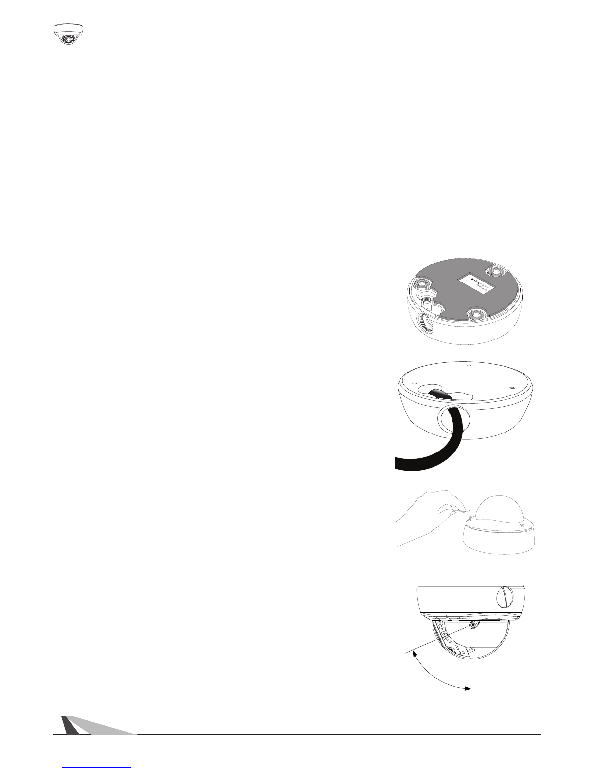
Step 1. Prepare for Installation
Important! DO NOT remove the protective plastic lm from the camera
dome until installation is complete and the camera is being sealed for
the last time.
A. Unpack the camera and locate the included foam gasket, hardware, mount-
ing template, silica packet, and 3mm Allen wrench. If a mounting accessory
is being used, unpack the accessory and become familiar with its installation
and use.
B. Apply the self-adhesive foam gasket to the base
of the camera.
C. If the camera will be connected using the 3/4”
conduit side entrance, remove the threaded plug
and route the wiring pigtail through the opening.
D. Use the 3mm Allen wrench to open the camera.
E. Review the lens angle-of-view limits and make sure
the camera location will allow it be aimed toward
the desired eld of view.
The setscrews for the gimbal should be factory preset to allow
adjustment without binding, but may be adjusted as needed
using a #1 or #2 Phillips screwdriver.
67.0°
67.0°
Page 9
WPS-565-DOM-A Installation Manual
9
© 2014 Wirepath Surveillance
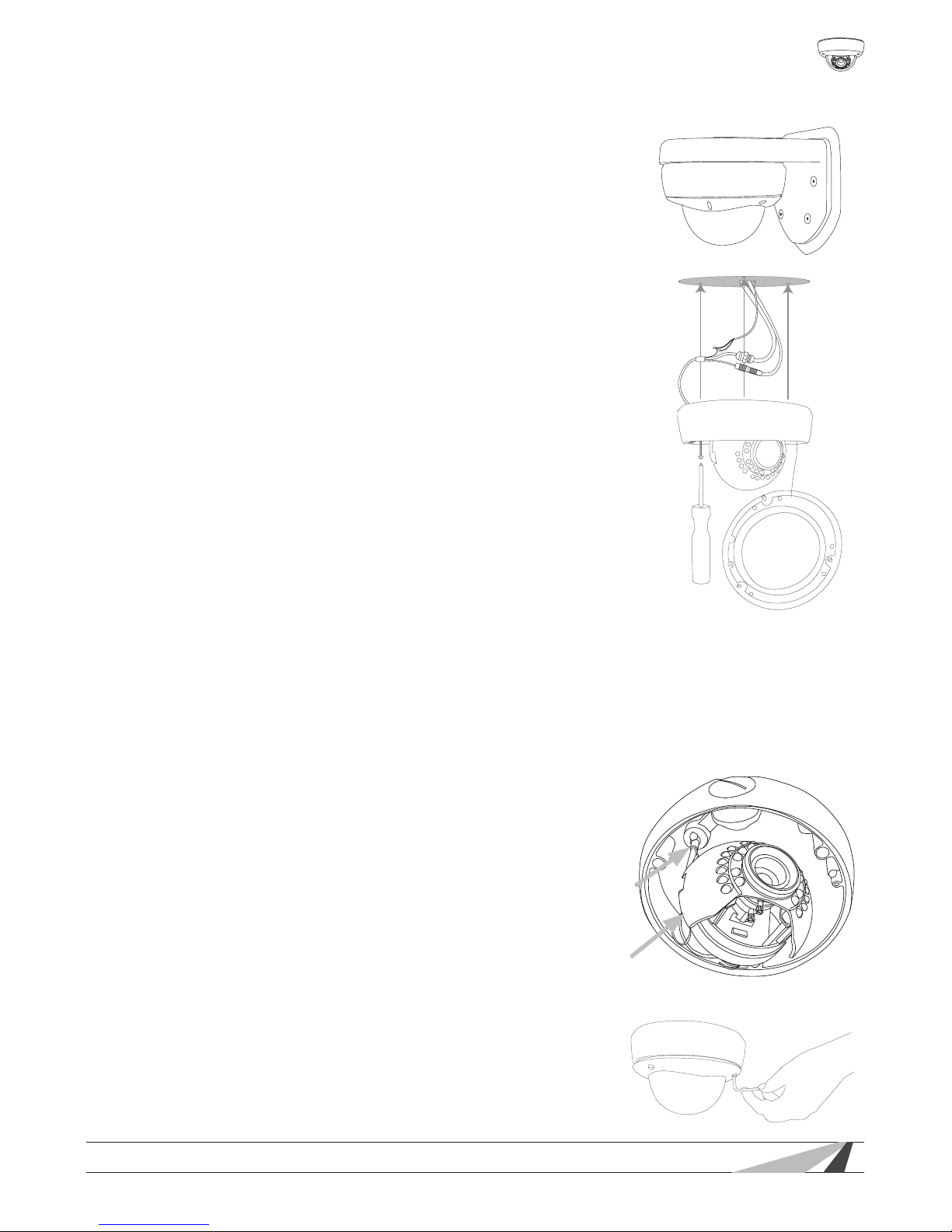
Step 2. Mount the Camera
Using Mounting Accessories
Mount the accessory according to its instructions, make
wiring connections, and mount the camera. Then,
continue these instructions below at Step 3 to complete
camera installation.
Surface Mounting
A. Use the included template to mark the screw loca-
tions for mounting.
B. Connect the camera to the wiring and move it into
position. Avoid pinching the wires between the camera and the mounting surface.
C. Use 3 of the included screws to secure the camera.
Insert the screws through the black mounting hole
gaskets and hand-tighten them evenly.
Step 3. Adjust Focus, Zoom, and Menu Settings
See “Camera Operation Setup” beginning on the
next page for instructions. Set the focus and zoom
adjustments, and adjust the OSD Setup Menu options as
needed. Disconnect the test adapter after completing
adjustments.
Step 4. Close the Camera
DO NOT remove the factory-installed silica desiccant packet in the camera.
A. Before closing the camera, remove
the spare silica packet from its
sealed foil package (taking care
not to rip the inner packet) and
place it inside the camera, out of
the lens’ eld of view. Do not remove the existing silica gel packet
strapped inside the camera.
B. Close the camera dome and use
the 3mm Allen wrench to tighten
the screws evenly. Remove the out-
erdomeprotectivelmlast.
Factory Silica Pack
(attached to wire)
Place New Pack
Behind Gimbal
Page 10
10
WPS-565-DOM-A Installation Manual
5. Camera Operation Setup
5.1. Focus, Zoom and Position
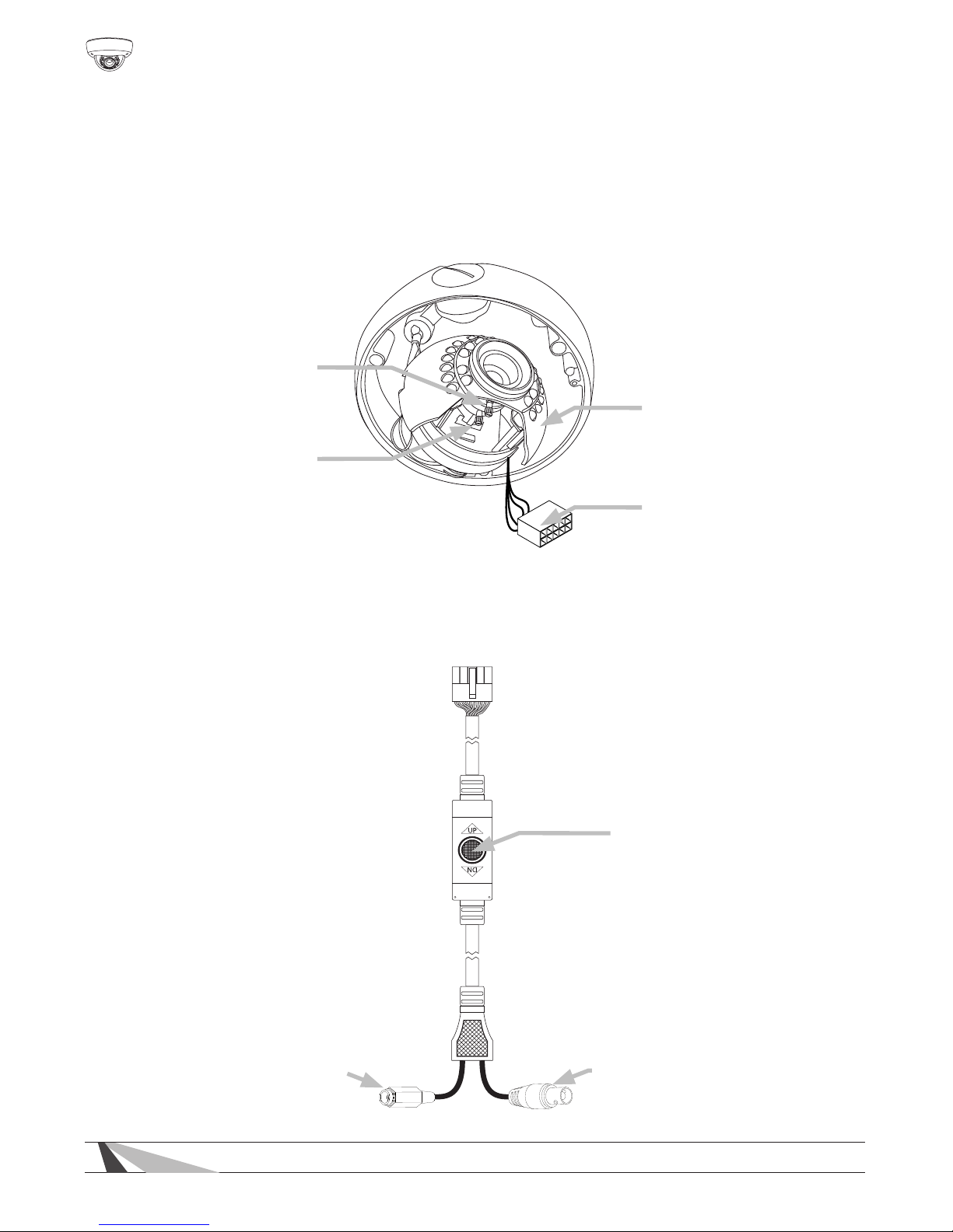
The lens of the camera has manual focus and zooms knobs for setting the
correct eld of view and the gimbal may be rotated for tilt correction. Connect
the test adapter as described below to use a monitor at the camera location for
viewing adjustments.
5.2. Using the Test Adapter
Connect to the “Test
Adapter” plug above.
Focus
(Front)
Zoom
(Rear)
Test Adapter
Connection
Rotate and Pivot Gimbal
(Loosen/tighten pivot setscrew
as needed, not shown. )
Test Adapter Connector
Connect the yellow BNC
adapter to a video monitor to
view the menu.
Use a BNC-RCA adapter to connect
to a TV’s yellow “Composite” input.
Connect the red power
plug to a 12V DC, 500mA
minimum power supply.
Use the center button to
navigate the OSD menu
structure.
Page 11
WPS-565-DOM-A Installation Manual
11
© 2014 Wirepath Surveillance
6. OSD SETUP Menu
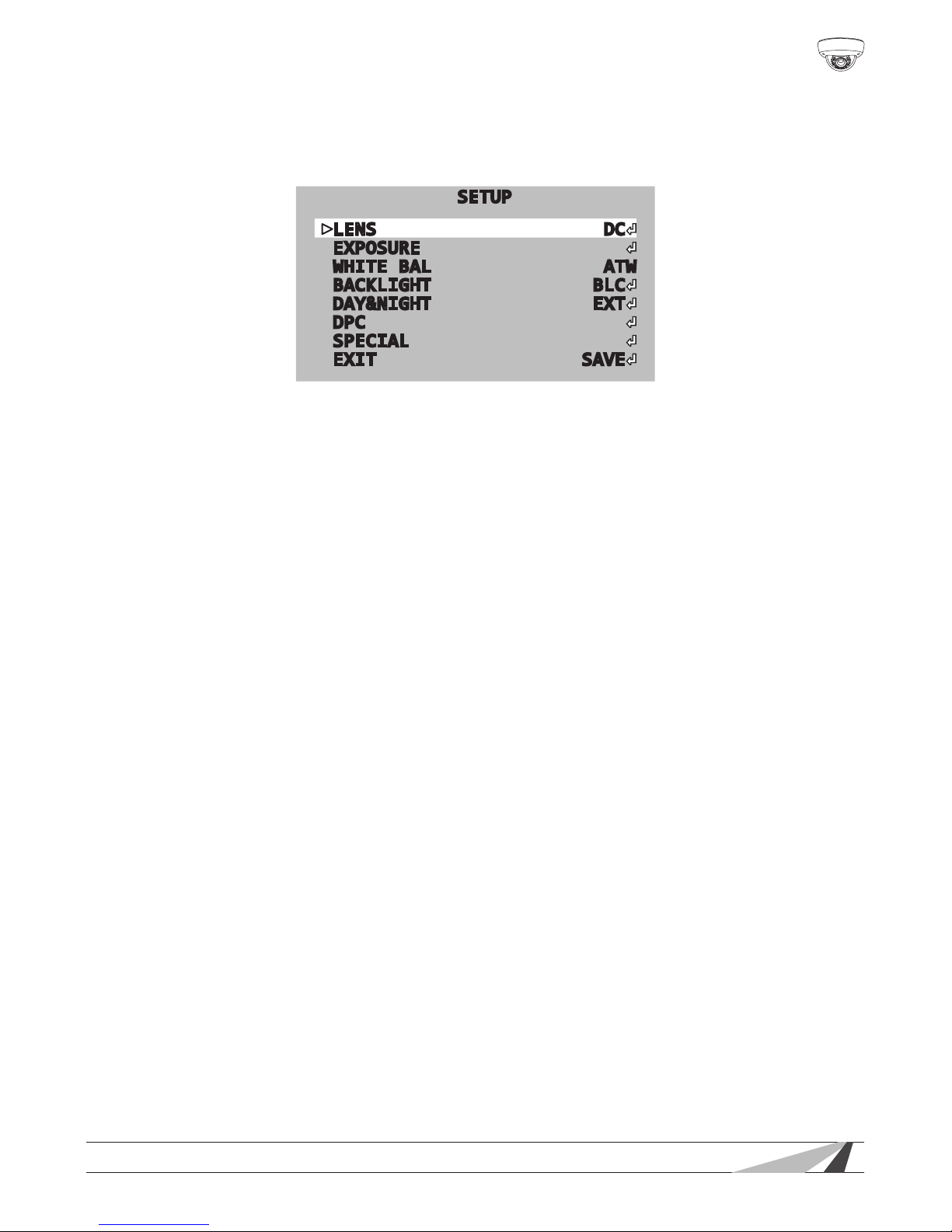
WPS-565 series cameras use an on-screen (OSD) menu system for setup of
advanced image and control settings.
SETUP
LENS DC
EXPOSURE
WHITE BAL ATW
BACKLIGHT BLC
DAY&NIGHT EXT
DPC
SPECIAL
EXIT SAVE
Default OSD menu view and settings
Use the OSD SETUP menu to:
• Improve image quality — change settings to suit any environment;
• Set up advanced image features — parking lane, dead pixel compensation,
motion detection, privacy masking, and more;
• Display custom text options — choose whether or not to display options like
camera ID and where to position overlaid text;
• CongureRS485—communicate between cameras and DVRs or other
security and automation systems.
6.1. Default Settings Description
Default settings for each SETUP menu section are written in bold type in the menu
overview to follow.
Defaults in the SETUP menu are optimized for the best balance of performance in
typical conditions:
• Daytime light should evenly illuminate the eld of view. Setting changes can
be made to accommodate for moderate brightness and contrast issues. Too
much direct sunlight or glare from reective and white surfaces should be
avoided.
• Night-time conditions should allow for the IR LEDs to reect on surfaces within
range, or for articial lighting to illuminate areas beyond IR range.
Page 12
12
WPS-565-DOM-A Installation Manual
6.2. How to Navigate the OSD SETUP Menu
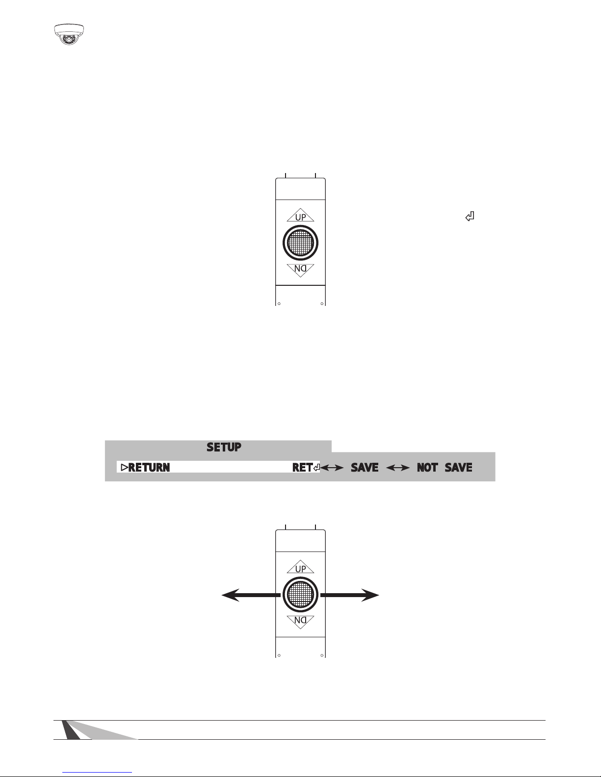
The OSD menu is displayed as an overlay of the camera eld-of-view. It will
remain visible as long as the menu is active. Use the test adapter or RS485 to
navigate. (use test adapter for initial setup. RS485 setup is detailed in section
“6.4.7.6. COMM ADJ. — RS485 Setup” on page 24)
6.2.1. OSD Joystick (Test Adapter)
6.2.2. How to Save Settings
Setting changes anywhere in the menu must be saved to take effect. Save
changes immediately from within the sub-menu (example below), or from the
main setup menu EXIT function (see “6.4.8. Exit Menu — Save and Reset” on
page 24).
Scroll down any menu page to the “RETURN” setting, and scroll left or right to
select whether settings are saved.
SETUP
RETURN RET SAVE NOT SAVE
Move the cursor left or right to select saving options.
Menu Navigation
Pivot the joystick up,
down, left and right to
move the white menu
cursor over the desired
option.
Sub-menus
Selections with a “ ”
to the far right have
a sub-menu. Press the
center joy-stick button
to access the menus.
Page 13
WPS-565-DOM-A Installation Manual
13
© 2014 Wirepath Surveillance
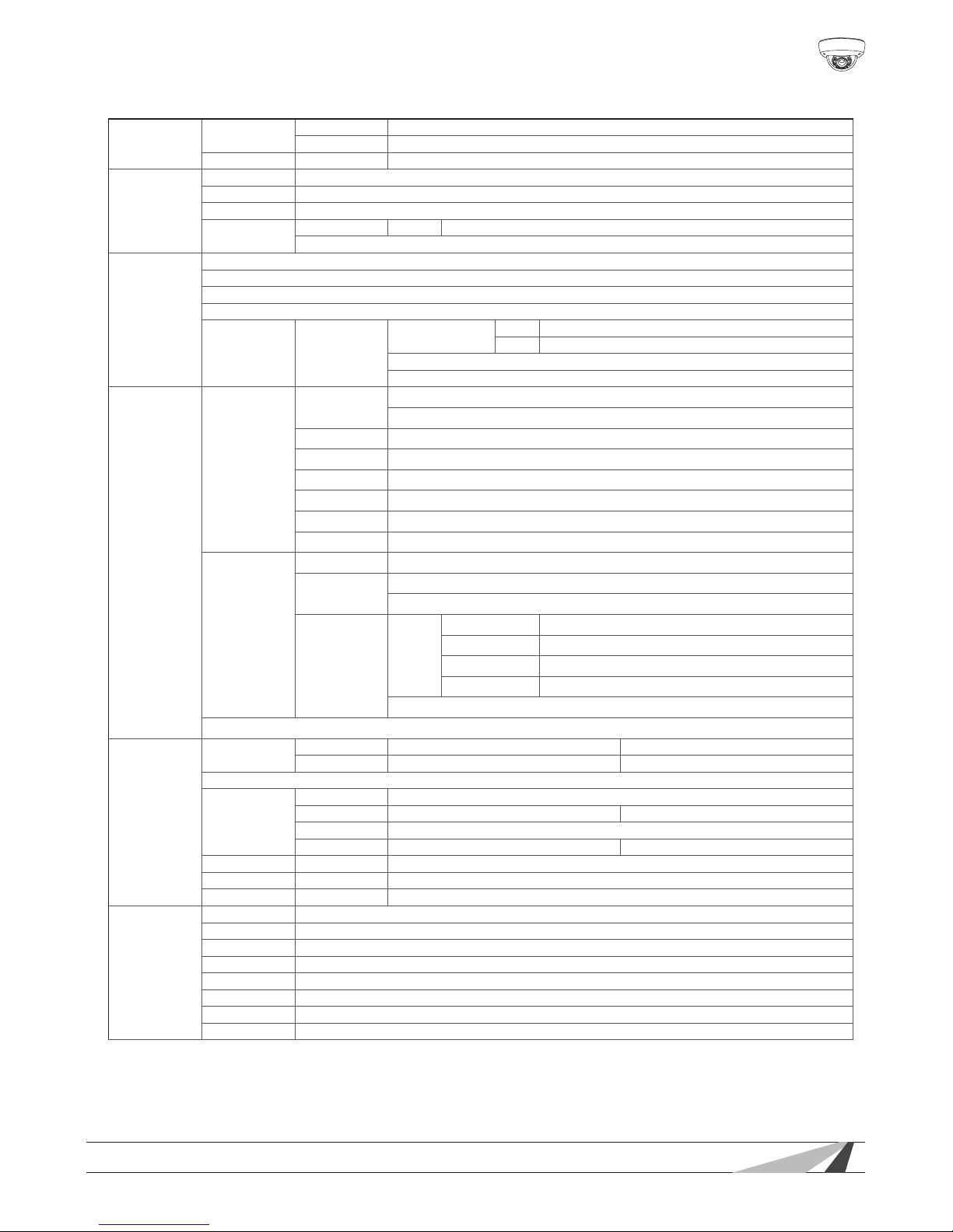
6.3. OSD Menu Structure Outline
LENS
DC
BRIGHTNESS 0...42...255
IRIS SPEED 0...4...15
MANUAL BRIGHTNESS 0...37...255
EXPOSURE
SHUTTER AUTO 1/60 FLK(1/120) 1/250 1/500 1/1000 1/2000 1/4000 1/5000 1/10000 1/100000
BRIGHTNESS 0...37...255
AGC OFF LOW MIDDLE HIGH
DWDR
ON LEVEL 0...35...63
OFF
WHITE BAL.
ATW
AWB
AWC->SE T
ANTI. CRL
MANUAL COLOR TEMP
MANUAL
BLUE 0...19...255
RED 0...24...255
OUTDOOR
INDOOR
BACKLIGHT
BLC
AREA SEL.
AR E A1 (on by default)
AREA2 (off by default)
ARE A STATE ON, OFF
GAIN 0...165...255
HEIGHT 0...10...15
WIDTH 0...4...15
LEFT/RIGHT 0...5...15
TOP/BOTTOM 0...5...15
HLC
LEVEL 0...150...255
MODE
NIGHT ONLY
ALL DAY
MASK SKIP
ON
HEIGHT 0...3...15
WIDTH 0...3...15
LEFT/RIGHT 0...6...15
TOP/BOTTOM 0...7...15
OFF
OFF
DAY&NIGHT
EXT
D→N DELAY 1 3 5 10 15 20 25 30 (seconds)
N→D DELAY 1 3 5 10 15 20 25 30 (seconds)
COLOR
AUTO
D→N LEVEL 0~192
D→N DELAY 1 3 5 10 15 20 25 30 (seconds)
N→D LEVEL 0~16
N→D DELAY 1 3 5 10 15 20 25 30 (seconds)
B/W BURST ON, OFF
IR SMART ON, OFF
IR LEVEL LOW, HIGH
DPC
START COVER LENS THEN ENTER
DPC VIEW OFF ON
LS VALUE 0...16...63
DIFF. 0...1...63
AREA HS 0...33...255
AREA HE 0...245...255
AREA VS 0...11...255
AREA VE 0...123...255
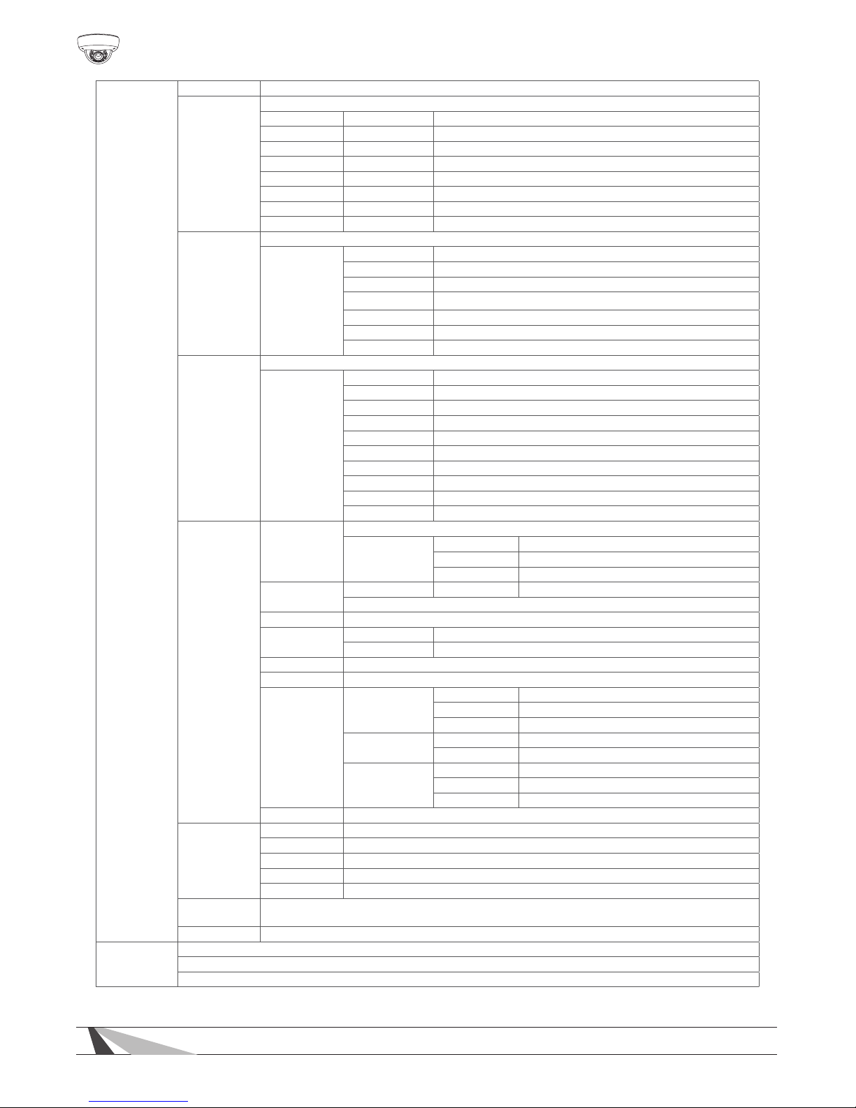
(Menu structure continued on next page)
Page 14
14
WPS-565-DOM-A Installation Manual
SPECIAL
CAM TITLE OFF ON
MOTION
OFF
ON AREA SEL. 1~4 (all 4 are on by default)
ARE A STATE ON OFF
HEIGHT 0...3...15
WIDTH 0...3...15
LEFT/RIGHT 0...2...15
TOP/BOTTOM 0...2...15
DEGREE 0...32...255
VIEW ON OFF
PRIVACY
OFF
ON
AREA SELECT 1~8 (all 8 a re on by default)
ARE A STATE ON OFF
HEIGHT 0...255 (default setting varies fo r each of the 8 areas)
WIDTH 0...255 (default setting var ies for each of the 8 areas)
LEFT/RIGHT 0...255 (default setting var ies for each of the 8 areas)
TOP/BOTTOM 0...255 (default setting varies for each of the 8 areas)
COLOR 0...15 (each number represents a different color)
PARK LINE
OFF
ON
LT 0...90...255
LB 0...32...255
RT 0...168...255
RB 0...228...255
F 0...18...255
N 0...65...255
T 0...4...15
V1 0...38...255
V2 0...46...255
V3 0...72...255
IMAGE ADJ.
LENS SHAD.
OFF
ON
LEVEL 0...13 0...255
H-CENTER 0...81...255
V-CENTER 0...22...255
2DNR
ON LEVEL 0...12 ...15
OFF
MIRROR OFF ON
FONT COLOR
FONT 0...3...15 (each number represents a different color)
ID&TITLE 0...3...15 (each number represents a different color)
CONTRAST 0...133...255
SHARPNESS 0...15...31
DISPL AY
LCD
GAMMA 0.30...0.40...1.00 (in 0.05 increments)
PED LEVEL 0...63
COLOR GAIN 0...224...255
CRT
PED LEVEL 0...16...63
COLOR GAIN 0...224...255
USER
GAMMA 0.30...0.45...1.00 (in 0.05 increments)
PED LEVEL 0...16...63
COLAR GAIN 0...224...255
NEG. IMAGE OFF ON
COMM ADJ.
CAM. ID 000...0 01...255
BAUD RATE 2400 4800 9600 19200 3840 0 5760 0
PROTOCOL NEXTCHIP PELCO-D PELCO -P
DISPLAY ID OFF ON
ID POS (Position the COMM ID using the directional keys)
LANGUAGE
ENGLISH, CHN2(Simplied Chinese), SPANISH, RUSSIAN, GERMAN, PORTUGUESE,
FRENCH, JAPANESE
VERSION 13 12 04
EXIT
SAV E
NOT SAVE
RESET
Page 15
WPS-565-DOM-A Installation Manual
15
© 2014 Wirepath Surveillance
6.4. OSD MENU SETTINGS
6.4.1. LENS Menu
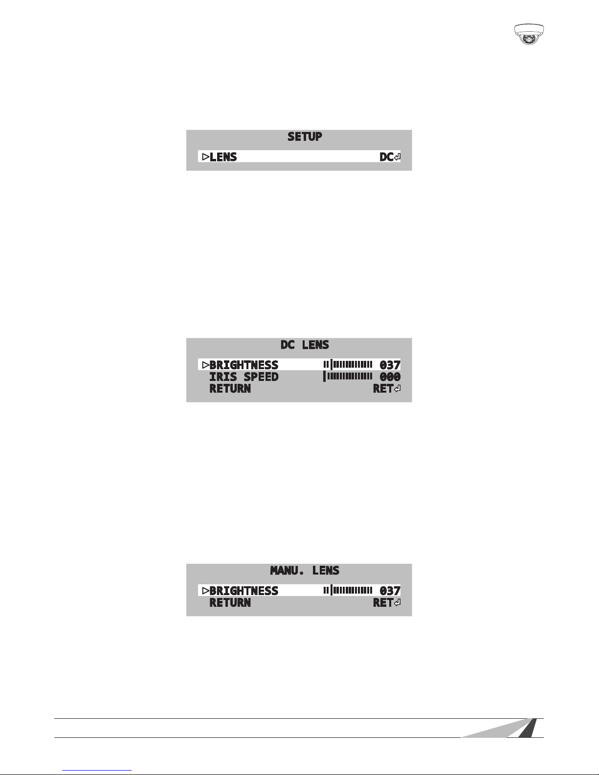
The amount of light entering the camera lens is controlled by the size of the
aperture, (called IRIS in SETUP menu).
SETUP
LENS DC
• The default DC setting is recommended when lighting levels vary regularly.
• For conditions with xed, low-level lighting, the MANUAL setting may be ideal.
Both settings offer additional setup options for ne tuning:
• Set the lens mode on the main setup screen. Move the joystick left and right to
select DC (Auto-IRIS), or MANUAL mode and enter each setting’s sub-menu.
6.4.1.1. DC Mode
DC mode is the recommended setting for outdoor locations and environments
with varying light conditions. In DC mode, the camera adjusts the aperture of the
lens automatically based on the lighting conditions of the environment.
DC LENS
BRIGHTNESS
||||||||||||||||
037
IRIS SPEED
|
|||||||||||||||
000
RETURN RET
• Brightness — Set level from 1(dark) to 255(bright). Too much brightness will
cause washing out. Too little will leave the picture too dim to view clearly.
• Iris Speed — Sets the reaction speed of iris changes related to light changes.
Leave the setting at 0 unless there is light strobing regularly in the scene
causing excessive variation in brightness.
6.4.1.2. MANUAL Mode
In this mode the aperture is set fully open and light level is not controllable.
This setting is only recommended for an environment with consistent lighting
conditions.
MANU. LENS
BRIGHTNESS
||||||||||||||||
037
RETURN RET
• Brightness — Set level from 1 (dark) to 255 (bright). Too much brightness will
cause washing out. Too little will leave the picture too dim to view clearly.
Page 16
16
WPS-565-DOM-A Installation Manual
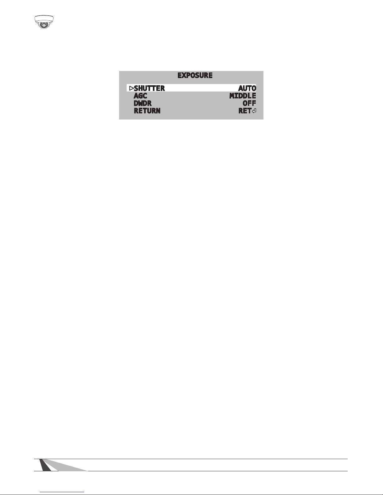
6.4.2. EXPOSURE Menu
Exposure settings use the sensor in the camera to control how much light is
recorded in each frame of video.
EXPOSURE
SHUTTER AUTO
AGC MIDDLE
DWDR OFF
RETURN RET
• Access the EXPOSURE sub-menu settings from the main SETUP menu.
6.4.2.1. SHUTTER
Electronic shutter speed controls how much light gets to the camera sensor with
each frame of video.
• Use the default AUTO setting in normal lighting conditions.
• Move the joystick left or right change the setting to any speed between 1/60
and 1/100000 or to FLK mode.
• Use a slower shutter speed for dim environments with xed lighting conditions.
• Use a faster shutter speed in bright environments with xed lighting conditions
or when fast-moving objects must be captured.
• Use FLK mode for scenarios where lighting or a television is causing visible icker
in the scene.
6.4.2.2. AGC (Auto Gain Control)
Auto Gain Control automatically amplies the video signal during low light
conditions. Use this setting to increase contrast in dimly lit parts of the scene.
• Use the default MEDIUM setting unless the scene is always very dark.
• Move the joystick left or right to turn AGC to LOW or OFF in areas that are
always well-lit.
• Too much amplication (HIGH) will cause distortion in the video feed, but may
be necessary for acheiving contrast in low light.
6.4.2.3. DWDR(Digital Wide Dynamic Range)
DWDR improves contrast between very dark and very bright areas for a more
balanced image. DWDR is OFF by default.
• Move the joystick left or right to turn DWDR ON and access the submenu:
• Adjust the level from 1 to 63 based on the environment.
• The higher the setting, the brighter the scene will appear.
• Too much DWDR in too bright a setting may cause the image to appear
washed out or colors to be somewhat inaccurate.
Page 17
WPS-565-DOM-A Installation Manual
17
© 2014 Wirepath Surveillance
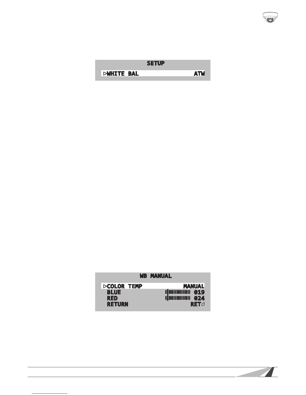
6.4.3. WHITE BALANCE Menu
White balance adjusts the image color according to the lighting conditions of
the scene to correct for different lighting color ranges.
SETUP
WHITE BAL ATW
• Move the joystick left or right to select the desired mode.
6.4.3.1. Auto Modes
Auto modes are preset to match the color needed for several common types of
light bulbs. Use the MANUAL setting below for other conditions. Move the joystick
left or right to change the mode.
• ATW1 — Auto Tracking White Balance, color temperature is set to 2000° K.
• ATW2 — Auto Tracking White Balance, color temperature is set to 2500° K.
• AWB — Auto White Balance
• ANTI CRL — (Anti Color Roll) Use to avoid rolling color under ourescent lights.
6.4.3.2. AWCSET Mode
This function is ideal for environments with the predominance of a single color.
For example, in a casino where the camera is pointed to a green table, the
color will be inaccurate. The overall tone of the picture will be too red. This mode
compensates the white balance and provides a more accurate color.
• Move the joystick left or right in the WHITE BAL menu to select AWCSET mode,
and press the OSD button for 3 seconds. The camera will automatically set the
white balance value based on the scene.
6.4.3.3. WB MANUAL Setting Mode
Use manual mode to correct for irregular lighting.
WB MANUAL
COLOR TEMP MANUAL
BLUE
||||||||||||||||
019
RED
||||||||||||||||
024
RETURN RET
• Move the joystick left or right in the WHITE BAL menu to select MANUAL and
enter the sub-menu.
• Select a manual preset for INDOOR or OUTDOOR conditions, or select MANUAL
to set blue and red values individually.
Page 18
18
WPS-565-DOM-A Installation Manual
6.4.4. BACKLIGHT Menu
Back Light Compensation (BLC, default) claries objects in front of bright light. For
example, in a scene with lighting facing the camera, if a person walks toward a
normal camera, they will appear as a silhouette, but BLC will adjust contrast for
more detail. BLC is ideal where the eld of view is focused close to the camera.
High Light Compensation (HLC) blocks bright light from causing white-out. For
example, with HLC, car headlights will appear to be blacked out and surrounding
light levels will be balanced enough to reveal details that would normally be
washed out. HLC is ideal for a wide eld of view focused far from the camera.
Use MASK SKIP to dene where BLC/HLC is active; for example, where bright light
only disrupts the top or bottom of a scene.
• Move the joystick left or right to select HLC or BLC and enter its sub-menu.
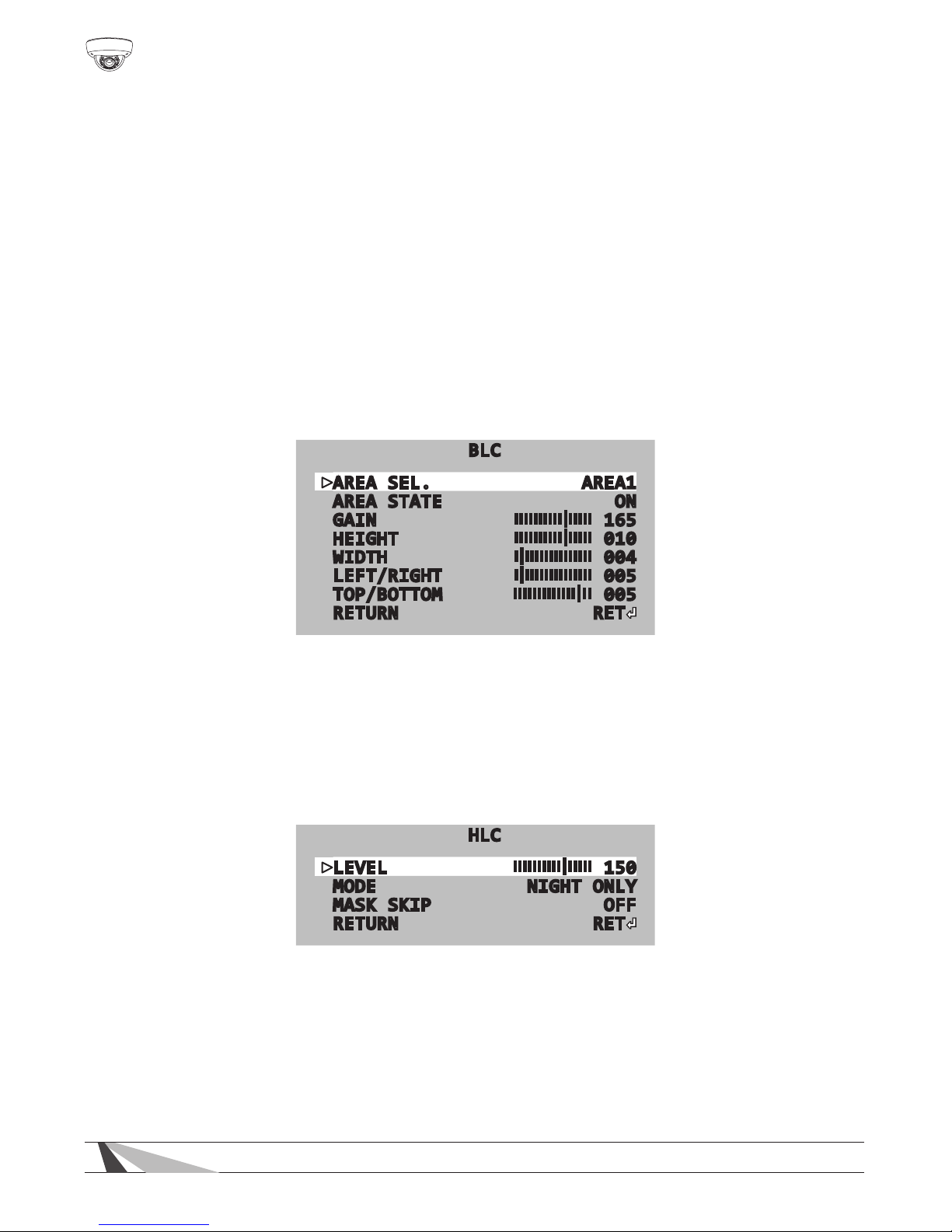
6.4.4.1. BLC (Back Light Compensation) Setup
BLC
AREA SEL. AREA1
AREA STATE ON
GAIN
||||||||||||||||
165
HEIGHT
||||||||||||||||
010
WIDTH
||||||||||||||||
004
LEFT/RIGHT
||||||||||||||||
005
TOP/BOTTOM
|||||||||||||
|
||
005
RETURN RET
• AREA SEL — Select AREA1 or AREA2 to adjust BLC values for that area.
• AREA STATE — Set BLC to OFF or ON in each area.
• GAIN — Adjust the level of BLC from 0~255.
• Set the BLC area by adjusting HEIGHT, WIDTH, LEFT/RIGHT, and TOP/BOTTOM.
6.4.4.2. HLC (High Light Compensation) Setup
HLC
LEVEL
||||||||||||||||
150
MODE NIGHT ONLY
MASK SKIP OFF
RETURN RET
• LEVEL — Adjust from 0 to 255. The larger the value, the more the camera will
black out light sources.
• MODE — Set to ALL DAY or NIGHT ONLY mode. NIGHT ONLY mode turns off HLC
unless the color mode is in black and white (BW).
• MASK SKIP — Turn ON and enter the sub-menu (not pictured) to size and position
the square MASK SKIP area.
Page 19
WPS-565-DOM-A Installation Manual
19
© 2014 Wirepath Surveillance
6.4.5. DAY & NIGHT Menu
The camera sensor has DAY (color) and NIGHT(black and white) mode. Use this
menu to set up the mode, how it is switched and also IR levels.
• Move the joystick left or right to select a mode and enter its sub-menu (if
applicable). Not all menus are displayed due to similarities in settings.
6.4.5.1. D&N EXT (External Sensor)
By default (D&N EXT), the color mode is set based on a light sensor on the front of
the camera. Recommended for most applications.
• D→NDELAY: Set delay for switching day (COLOR) to night (B/W) mode. Set from
0 to 30 seconds. Increase if night mode switches on too quickly.
• N→DDELAY:Set delay from Night to Day mode (opposite of above). Set from 0
to 30 seconds. Increase if day mode switches on too quickly.
6.4.5.2. D&N COLOR Mode
Lock the camera in COLOR (daylight) mode. IR will NOT activate in this mode, so
the ambient lighting level must be sufcient for viewing.
6.4.5.3. B/W Setting
Lock the camera in B/W (night time) mode. IR intensity may also be set.
• BURST — Turn ON and image is converted to a grey image containing the color
signal. OFF sends a true B/W image containing no color signal.
• IR SMART — Prevents over-exposure by reducing IR LED intensity when objects are
too close to the camera. Scroll left or right to turn ON or OFF.
• IR LEVEL — Scroll left or right to set the IR output level to HIGH or LOW.
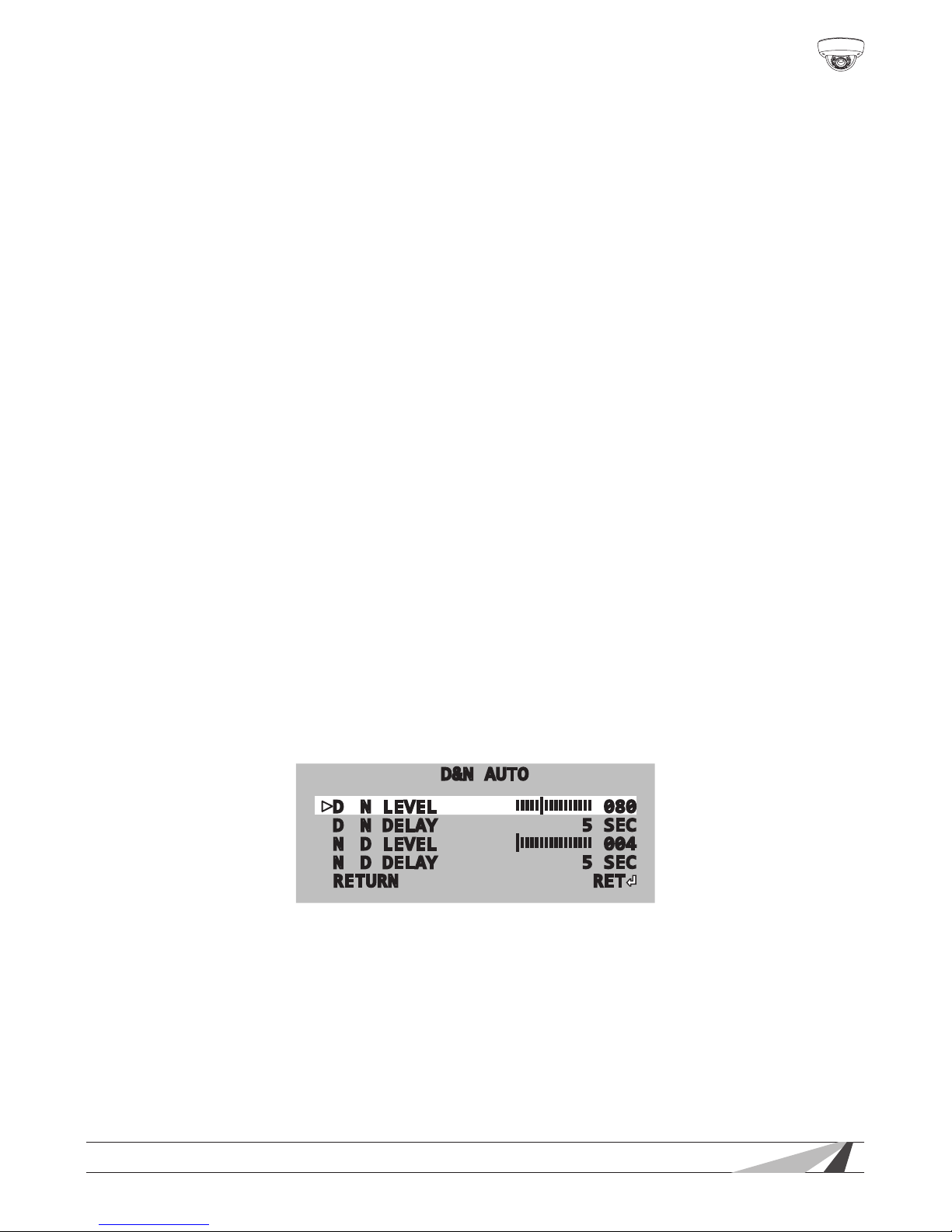
6.4.5.4. D&N AUTO Setting
In this mode, the camera uses the light entering the sensor to determine daytime
(COLOR) or nighttime (BW) mode.
D&N AUTO
DN LEVEL
||||||||||||||||
080
DN DELAY
5 SEC
ND LEVEL
|
|||||||||||||||
004
ND DELAY
5 SEC
RETURN RET
• D > N LEVEL — Set the light level required to switch from COLOR to B/W mode.
Increase if the camera switches to B/W mode too early at night.
• D > N DELAY — Set the delay for switching to B/W mode. Increase if the camera
uctuates between COLOR and B/W mode early at night.
• N > D LEVEL — Set the light level required to switch from B/W to COLOR mode.
Increase if the camera switches to COLOR mode too late in the morning.
• N > D DELAY — Set the delay for switching to COLOR mode. Increase if the
camera uctuates between B/W and COLOR mode early in the morning.
Page 20
20
WPS-565-DOM-A Installation Manual
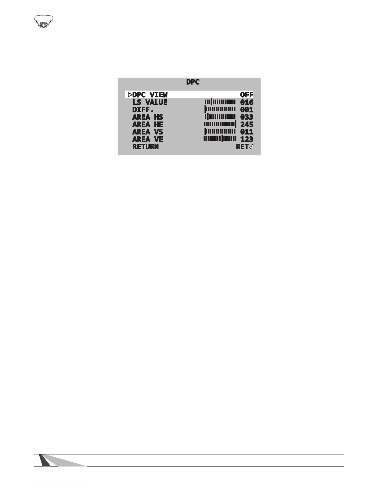
6.4.6. DPC (Dead Pixel Compensation)
Dead Pixel Compensation automatically removes defective pixels and “lls in”
the image. Use the UP arrow function to exit this menu without performing DPC.
DPC
DPC VIEW OFF
LS VALUE
||||||||||||||||
016
DIFF.
|
|||||||||||||||
001
AREA HS
||||||||||||||||
033
AREA HE
||||||||||||||||
|
245
AREA VS
|
|||||||||||||||
011
AREA VE
|||||||||||||||||
123
RETURN RET
• START — Covers the lens and then press ENTER allow the camera to search for
dead pixels.
• DPC View— Turn ON to see where compensation is active.
• LS VALUE — The speed at which the shutter closes. Higher value means faster
speed.
• DIFF. — (Diffusion) Higher value means the dead pixel spots are expanded.
• AREA HS — Adjust the right box line on screen, from 0 to 255.
• AREA HE — Adjust the left box line on screen, from 0 to 255.
• AREA VS — Adjust the top box line on screen, from 0 to 255.
• AREA VE — Adjust the bottom box line on screen, from 0 to 255.
Page 21
WPS-565-DOM-A Installation Manual
21
© 2014 Wirepath Surveillance
6.4.7. SPECIAL Menus
6.4.7.1. CAM TITLE Setting
The CAM TITLE sub-menu provides the ability to set a camera name and have it
appear on the screen.
• CAM TITLE — Set to ON to display the camera name on the screen.
• Set a camera name by selecting one letter/number at a time using the menu
at the bottom of the screen. Assigning a name that highlights the location of
the camera such as Lobby, Main Hall, etc. is recommended.
• Press CLR to clear all letters, press POS to choose the position of CAM NAME on
the screen, and press END to exit the menu.
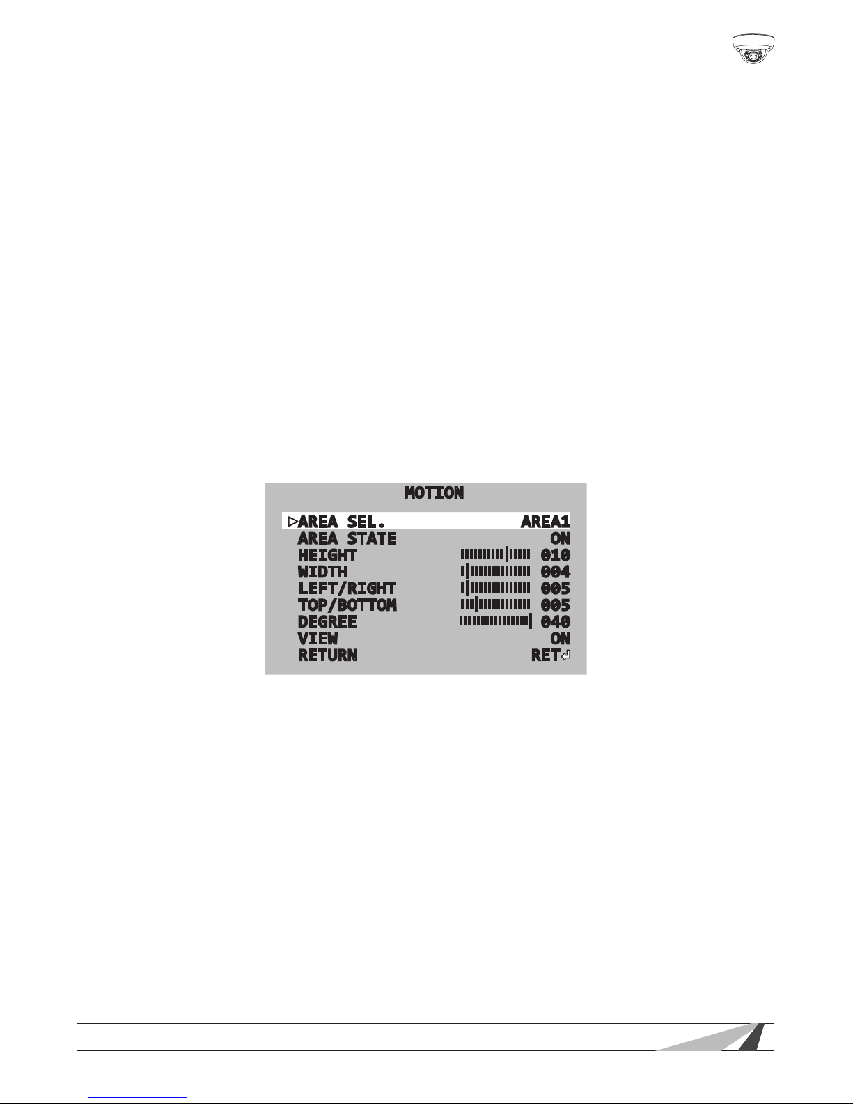
6.4.7.2. MOTION Detection
Motion Detection allows for up to 4 zones of motion detection. When an
object in one of the zones moves, the camera will highlight motion in magenta
rectangles. This allows for monitoring motion more efciently.
Scroll left or right to set MOTION DET to ON and enter into the Motion sub-menu.
MOTION
AREA SEL. AREA1
AREA STATE ON
HEIGHT
||||||||||||||||
010
WIDTH
||||||||||||||||
004
LEFT/RIGHT
||||||||||||||||
005
TOP/BOTTOM
||||||||||||||||
005
DEGREE
||||||||||||||||
|
040
VIEW ON
RETURN RET
• AREA SEL. — Select from zones 1~4 to adjust the motion detection settings of
that area(zone).
• AREA STATE — Set to ON to display the detection zone on the screen: set to
OFF to hide the detection zone on the screen.
• Customize the size and the position of each detection zone by adjusting
HEIGHT, WIDTH, LEFT/RIGHT, TOP/BOTTOM values.
• DEGREE — Increase to raise motion detection sensitivity.
• VIEW — When set to ON, the screen will highlight motion of the moving object
with magenta rectangles.
Page 22
22
WPS-565-DOM-A Installation Manual
6.4.7.3. PRIVACY Setting
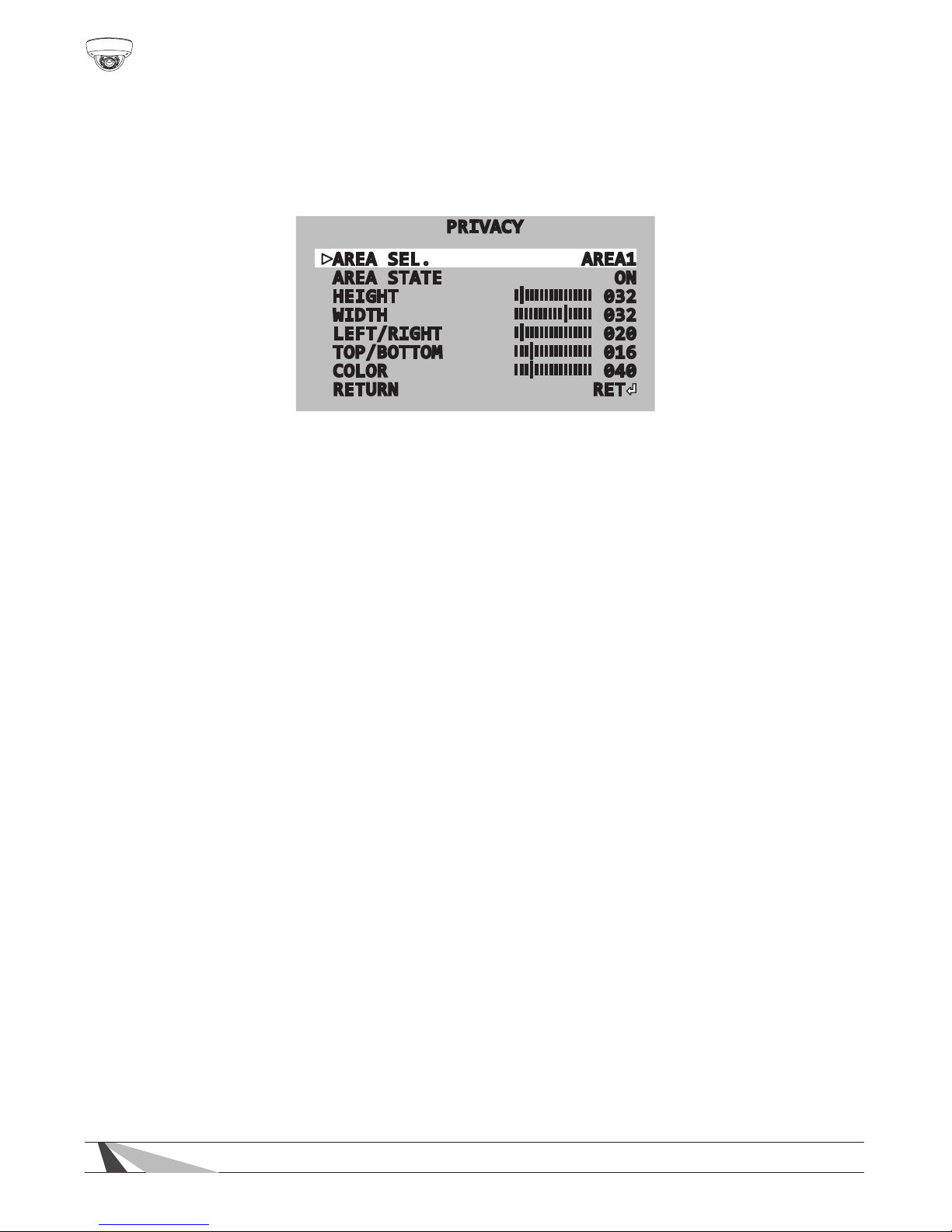
Privacy Mask allows the masking of up to 8 “surveillance-free” zones in the eld of
view. This may be used for a camera that has a neighbor’s window in part of the
scene, or with an area where sensitive information would be visible.
PRIVACY
AREA SEL. AREA1
AREA STATE ON
HEIGHT
||||||||||||||||
032
WIDTH
||||||||||||||||
032
LEFT/RIGHT
||||||||||||||||
020
TOP/BOTTOM
||||||||||||||||
016
COLOR
||||||||||||||||
040
RETURN RET
• PRIVACY MASK — Set to ON to enter into the sub-menu.
• AREA SEL — Select zone 1-8 to adjust a region.
• AREA STATE — Set to ON to show the privacy zone mask on the screen. Set to
OFF to hide the privacy zone mask.
• Customize the size and the position of privacy zone by adjusting HEIGHT,
WIDTH, LEFT/RIGHT, and TOP/BOTTOM values.
• COLOR — Options for mask color include 16 different colors for each privacy
zone. Change the color by selecting a value from 0 to 15.
6.4.7.4. PARK LINE Setting
The PARK LINE function may be useful if the camera is used in a mobile
application. The parking line can be aligned with objects in the eld of view.
• LT — Adjust the top left area on screen, from 0 to 195 steps.
• LB — Adjust the bottom left area on screen, from 0 to 194 steps.
• RT — Adjust the top right area on screen, from 0 to 194 steps.
• RB — Adjust the bottom right area on screen, from 0 to 194 steps.
• F — Adjust the front area on screen, from 0 to 68 steps.
• N — Adjust the near area on screen, from 0 to 68 steps.
• T — Adjust the parking line thickness, from 0 to 15 steps.
Page 23
WPS-565-DOM-A Installation Manual
23
© 2014 Wirepath Surveillance
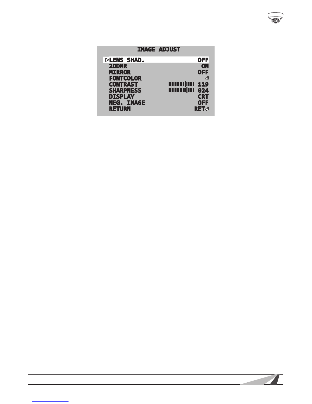
6.4.7.5. IMAGE ADJ. Setting
IMAGE ADJUST
LENS SHAD. OFF
2DDNR ON
MIRROR OFF
FONTCOLOR
CONTRAST
||||||||||||||||
119
SHARPNESS
|||||||||||
|
||||
024
DISPLAY CRT
NEG. IMAGE OFF
RETURN RET
• LENS SHAD. — This feature brightens the corners of the image when using a
wide angle view. Scroll left or right to toggle OFF or ON.
• 2DNR — 2D-DNR digital noise reduction produces clear images in low light
conditions. Not only does it help to reduce image noise, but it also minimizes
the object from becoming blurred when in motion. Scroll left or right to toggle
OFF or ON.
• MIRROR — Allows the image to be mirror reversed. Typically used in vehicles or
mobile applications. Scroll left or right to toggle OFF or ON.
• FONT COLOR — Enter the sub-menu (not pictured) to change the font color,
size, and position. There are 16 options for the OSD Font Color and CAM TITLE
color. Change colors by selecting a value from 0 to 15 steps.
• CONTRAST — When increasing the contrast value, dark colors become darker
and light colors become lighter. The value ranges from 0 to 255.
• SHARPNESS — Adjust the clarity of the image. The higher th value the more
claritty, but too high a setting will have extra noise. The value ranges from 0 to
31.
• DISPLAY — Scroll left or right to select CRT, LCD, or USER depending on the type
of monitor used to view the camera. CRT sub-menu adjustments include:
• PED LEVEL — The higher the value, the brighter the image.
• COLOR GAIN — The higher the value, the darker the image.
• GAMMA — Standard value is 0.55. Adjust between 0.05 ~1.00. To correct
color issues.
• NEG. IMAGE — Offers a wider dynamic range and preserves most detail
because it displays data exactly as the CCD sees it. Select ON for images with
the most light intensity and color information.
Page 24
24
WPS-565-DOM-A Installation Manual
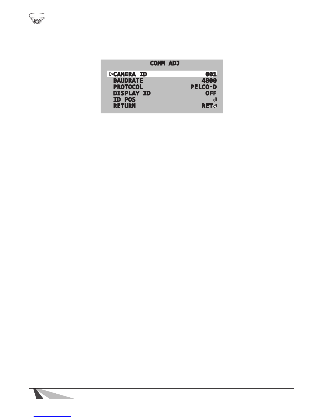
6.4.7.6. COMM ADJ. — RS485 Setup
Set up remote control of the camera’s OSD SETUP menu from a PTZ controller or
DVR through RS485.
COMM ADJ
CAMERA ID 001
BAUDRATE 4800
PROTOCOL PELCO-D
DISPLAY ID OFF
ID POS
RETURN RET
• CAM ID — Scroll left or right to select a unique ID number from 0 to 225 to
identify the camera on the RS485 loop.
Note: Each device in the RS485 connection MUST be set to a unique address
number for proper RS-485 communication.
• BAUD RATE — Scroll left or right to choose a baud rate for RS485
communication between the camera and controller. Baud rate options
include 4800, 9600, 19200, 38400, and 57600.
Note: ALL devices in the RS485 connection must be set to the same baud rate
for proper RS-485 communication.
• PROTOCOL — Scroll left or right to select a communication protocol - PELCO-D
or PELCO-P. Wirepath devices use Pelco-D.
• DISPLAY ID — Scroll left or right to set DISPLAY ID to ON and show the CAMERA
ID on the screen. This feature is useful when needing to know the ID of a
camera simply by viewing a picture.
• ID POS — Scroll left or right to set the position for the CAMERA ID on the display
screen.
6.4.8. Exit Menu — Save and Reset
After making changes, settings should be saved either in the sub-menu, or, by
using the SAVE function in the EXIT menu. If adjustment to the camera’s settings
results in poor picture quality, settings may be discarded (NOT SAVE) or RESET:
6.4.8.1. SAVE
Save all current settings and exit the SETUP menu.
6.4.8.2. NOT SAVE
Discard all unsaved changes and exit the SETUP menu.
6.4.8.3. RESET
All congurations with the exception of the COMM SETTINGS will be reset back to
factory default settings. This option does not have an “UNDO” feature, so ensure
default settings are desired before selecting this function. The cursor will return to
the top of the SETUP menu after the reset is complete.
Page 25

WPS-565-DOM-A Installation Manual
25
© 2014 Wirepath Surveillance
7. Troubleshooting
If you have trouble operating the camera, rst refer to the following
guidelines. If the problem persists, contact Technical Support at (866)
838-5052.
Nothing appears on the display:
• Check if the power for the camera and the monitor is ON.
• Check if the VIDEO cable is connected to the camera BNC video
output jack.
• Check if the VIDEO cable is connected to the monitor VIDEO input
jack.
Image appears dim on the display:
• Check the monitor contrast setting.
• Check the monitor brightness setting.
• Check the lens. If necessary, clean with a soft, clean eyeglasses
cloth.
• Check if the camera is facing towards a bright light. If so, change
the camera position.
• If a device exists between the camera and screen, conrm the
signal accepted by the screen is strong enough – 75 Ohm.
Image appears blurry on the display:
• Check the focus of the lens.
• Check the lens. If necessary, clean with a soft, clean eyeglasses
cloth.
The camera is not working properly and the camera housing is hot:
• Check if camera is connected to the correct power source.
Condensation Appears on Camera Lens Cover:
• Add a new silica desiccant pack inside the camera housing.
Camera Power Cycles Intermittently:
• Check voltage at camera for proper voltage level.
• Connect camera locally with a different power supply to test.
Page 26

26
WPS-565-DOM-A Installation Manual
8. Specications
Imaging
Image Sensor 960H 1/3" Color Sony Super HAD II
Lens 2.8 ~ 12mm Auto Iris Vari-Focal Lens
Estimated Horizontal Viewing Angle 92˚(W)~30˚(T)
Resolution (TVLs) 700
Effective Pixels NTSC:976(H)x494(V)
Gamma 0.45
S/N Ratio >50dB
Sync. Mode Internal Sync
Scanning System 2:1 Interlace
Auto IRIS Yes
IR Range 65ft
Smart IR Yes
True Day / Night Yes
Technology
OSD Yes
WDR Yes
DNR Yes
Minimum Illumination 0.01 Lux color, 0 Lux IR on
Highlight Compensation Yes
Auto Gain Control Yes
Back Light Compensation Yes
White Balance Yes
Lens Correction Yes
Privacy Mask Yes
Motion Detection Yes
Mirror Mode Yes
Parking Line Yes
Housing and Power
Weather Rating IP66
Vandal Resistant Yes
Side Conduit Threading 3/4” NTP
RS485 Yes
Operating Temperature 14°F-140°F
Operating Humidity 30%-80% RH
Power Source
(Not Included)
Main Power 12V DC or 24V AC (500mA minimum)
Test Adapter 12V DC (500mA minimum)
Power Consumption 4.5W 375mA
Dimensions See Dimensions (next page)
Weight 2 lbs
Page 27
WPS-565-DOM-A Installation Manual
27
© 2014 Wirepath Surveillance
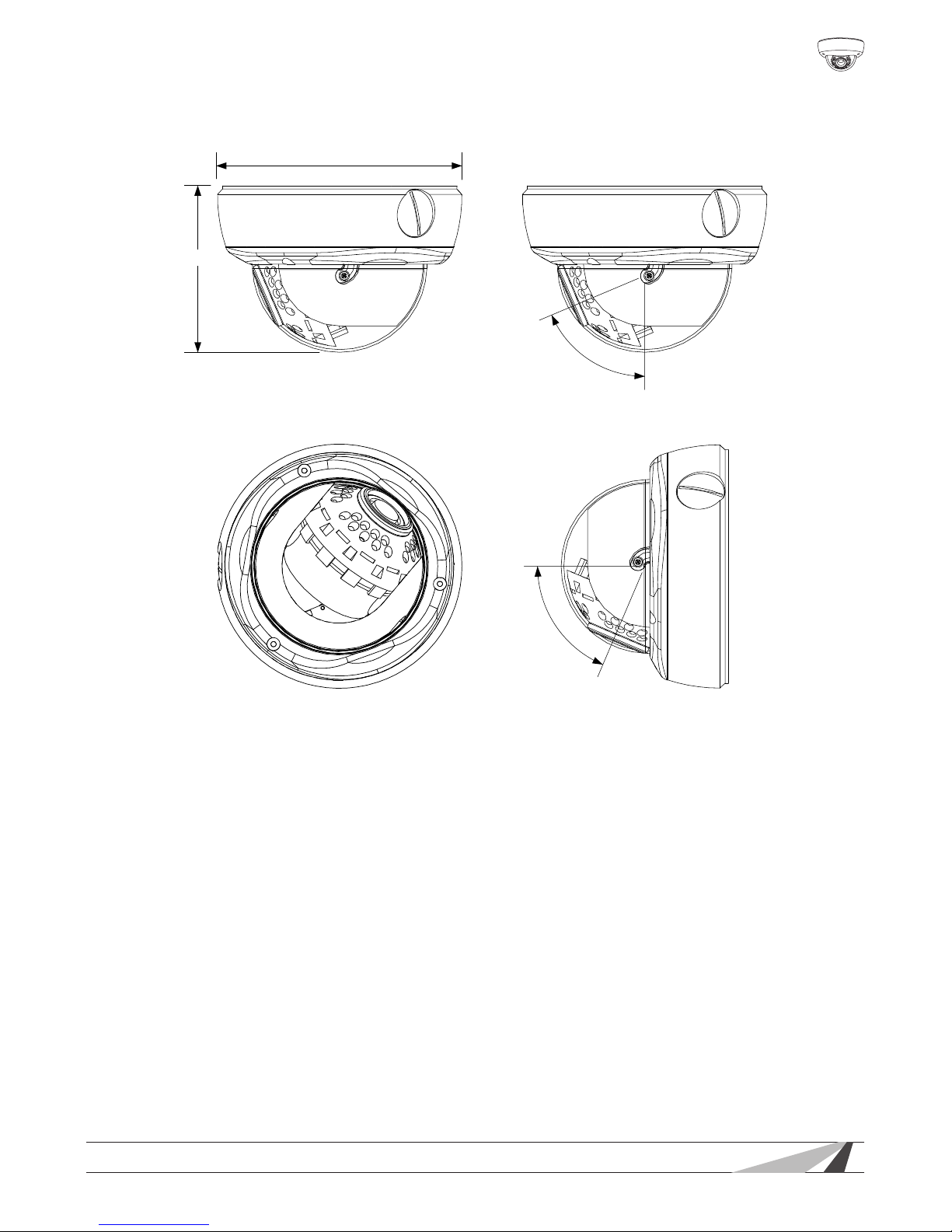
9. Dimensions
Top View
Side View
5.91"
4.04"
67.0°
67.0°
Maximum Camera Angle
10. 5-Year Limited Warranty
This camera has a 5-Year Limited Warranty. The warranty includes parts and labor
repairs on all components found to be defective in material or workmanship
under normal conditions of use. This warranty shall not apply to products which
have been abused, modied, disassembled or improperly installed. Products
to be repaired under this warranty must be returned to Wirepath™ Surveillance
or a designated service center with prior notication and an assigned return
authorization number (RA).
11. Contacting Technical Support
Phone: (866) 838-5052
Email: [email protected]
Page 28
140422-1720
© 2014 Wirepath Surveillance
 Loading...