

Page 1

User Manual
SiteWERX Location Node
1 June 2009
Page 2

SiteWERX User Manual WirelessWerx
Table of Contents
1. Scope ...........................................................................................................1
1.1 Safety Instructions .......................................................................................................... 1
1.2 Contact Information......................................................................................................... 1
2. Description ..................................................................................................2
2.1 SiteWERX Location Node (SLN) ..................................................................................... 3
2.1.1 Architecture ............................................................................................................. 3
2.1.2 Bluetooth Module .................................................................................................... 4
2.1.3 Operating Voltage and Current ............................................................................... 4
2.1.4 Antenna ................................................................................................................... 5
2.1.5 Development/Programming Interface ..................................................................... 6
2.1.6 Status Indicators ..................................................................................................... 6
2.1.7 Enclosure ................................................................................................................ 6
2.1.8 Environment ............................................................................................................ 6
3. Constraints ..................................................................................................7
4. Reference Documentation .........................................................................7
4.1 Acronyms/Abbreviations ................................................................................................ 7
Table of Figures
Figure 1. SiteWERX Location System .................................................................................................. 2
Figure 2. SiteWERX Location Node Block Diagram ........................................................................... 3
Figure 3. SLN Antenna Dimensions ..................................................................................................... 5
Figure 4. Antenna Radiation Pattern .................................................................................................... 5
SiteWERX ii 1June09
Page 3

SiteWERX User Manual WirelessWerx
1
1. Scope
This document provides user information for the SiteWERX Location Node.
Information is included regarding safety, technical features, installation, and operating
constraints
1.1 Safety Instructions
a. Read the manual carefully before use.
b. The node and power supply shall be installed according to the
installation instructions.
c. The node and power supply are for indoor use only.
d. The AC power cable plug has three pins. The third pin is for maintaining the
chassis at ground potential. Do not remove it.
e. Do not over load the power supply. Refer to paragraph xx for proper load levels.
f. Ensure that power is OFF during installation procedures.
g. All maintenance and servicing should be performed or supervised by qualified
service personnel.
h. To satisfy RF exposure requirements, this device and its antenna must operate
with a separation distance of at least 20 cm from all persons and must not be colocated or operating in conjunction with any other antenna or transmitter.
1.2 Contact Information
This product is manufactured by:
WirelessWERX, Inc.
100 Chaparral Court, Suite 100
Anaheim, CA 92808
Phone: 714-685-9776
Fax: 714-685-9270
SiteWERX 1June 09
Page 4

SiteWERX User Manual WirelessWerx
2
SiteWERX
Management
Console
PC
LAN
SiteWERX Base Station SLN1
Bluetooth Bluetooth
SLN 2
SLN 3
Bluetooth
Cell
Phone
SMC
Bluetooth
2. Description
The SiteWERX Location system consists of System Management software residing
on a networked PC, a Base Station, and one or more SiteWERX Location Nodes
(SLN’s), Figure 1.
The Base Station and SLN’s form a communication chain (scatternet) using Bluetooth
radios. The Base Station maintains a communication link with the Management
Console, allowing the system to be managed by a PC. Mobile devices, such as cell
phones and PDAs, running the SiteWERX Mobile Client (SMC) software are able to
communicate with an SLN to receive location and real-time messages, reference
Figure 1.
Figure 1. SiteWERX Location System
SiteWERX 1June 09
Page 5
SiteWERX User Manual WirelessWerx
3
Input Voltage
12 VDC
Transceiver
Controller & Memory
Link with Location
Nodes, cell phones &
PDAs
Bluetooth
Module
Development/
Programming Interface
3.3 VDC
Regulator
SiteWERX Location
Node Module
2.1 SiteWERX Location Node (SLN)
The SLN has the following functional capabilities.
a) Operates as a Bluetooth device in accordance with the Bluetooth 2.0 + EDR
b) Establishes wireless links with other Bluetooth devices in proximities of 1 to 10
meters
c) Transmits area-specific information to other Bluetooth devices in support of
precision location
d) Transmits and receives information to and from other Bluetooth devices in support of
system administration, status and diagnostics, and alarm/alert situations.
2.1.1 Architecture
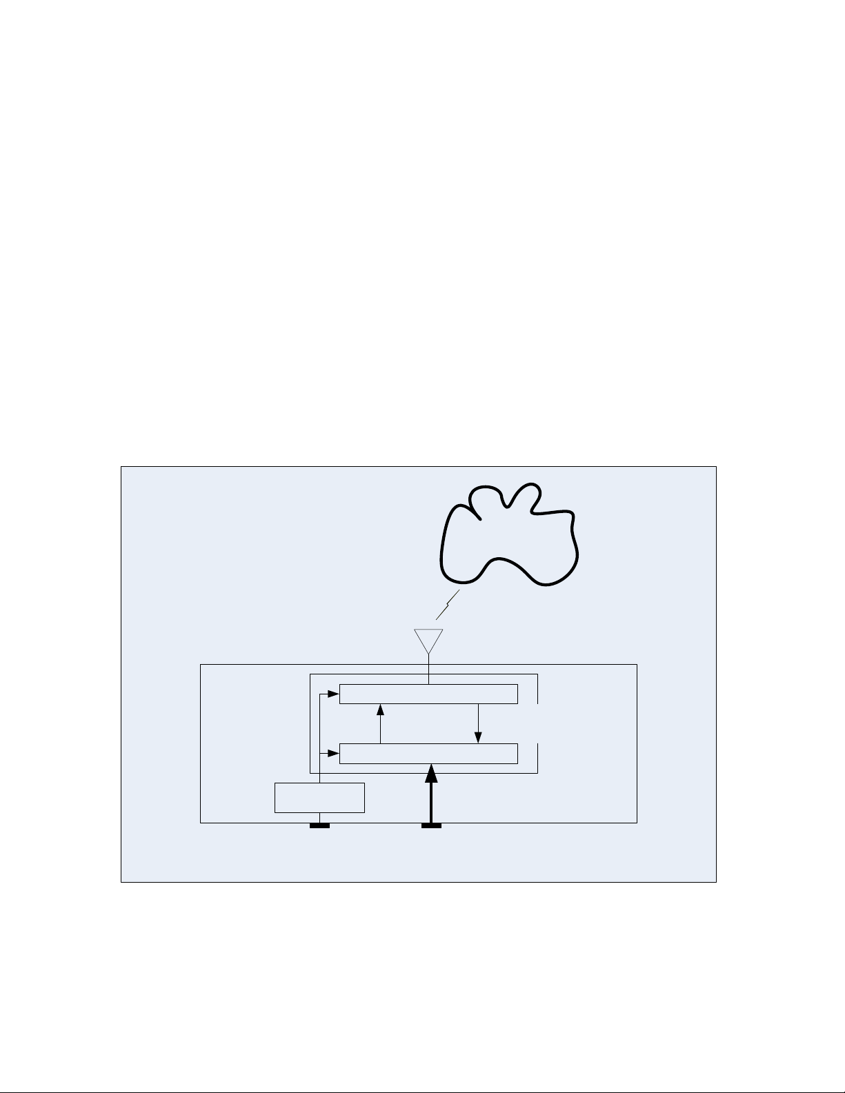
The SiteWERX Location Node module consists of a Bluetooth Module for Bluetooth
operations, an antenna, and a voltage regulator. A functional block diagram of the
SiteWERX Location Node is shown in Figure 2
Figure 2. SiteWERX Location Node Block Diagram
SiteWERX 1June 09
Page 6

SiteWERX User Manual WirelessWerx
4
2.1.2 Bluetooth Module
The SLN has a CSR BlueCore4-External radio to provide the operating parameters
and protocols required by the Bluetooth 2.0 + EDR Core Specification.
2.1.2.1 Radio Characteristics, Basic Data Rate
Receiver Typical Bluetooth Spec Unit
Sensitivity @ 0.1% BER - 83 ≤ - 70 dBm
Transmitter Typical Bluetooth Spec Unit
Max RF Transmit Power + 4 - 6 to + 4 dBm
2.1.2.2 Radio Characteristics, Enhanced Data Rate
Receiver Typical Bluetooth Spec Unit
Sensitivity @ 0.1% BER -83 ≤ - 70 dBm
Transmitter Typical Bluetooth Spec Unit
Max RF Transmit Power + 4 - 6 to + 4 dBm
2.1.3 Operating Voltage and Current
The SLN is connected to a power distribution network powered by an AC/DC
converter.
The SLN operates with an input of 6 to 15 volts DC, and has a maximum operating
current of ≤ 0.070 Amps.
A voltage regulator provides 3.3 volts DC to the Bluetooth module
t
SiteWERX 1June 09
Page 7
SiteWERX User Manual WirelessWerx
5
AF
2.4
0.09"
Pin 1
Feed termination
Pin 2
No electrical connection
For physical support only
Solder termination
0.26"
0.04"
Connects to receiver and transmitter
Polarization Axis,
E-Field
2.1.4 Antenna
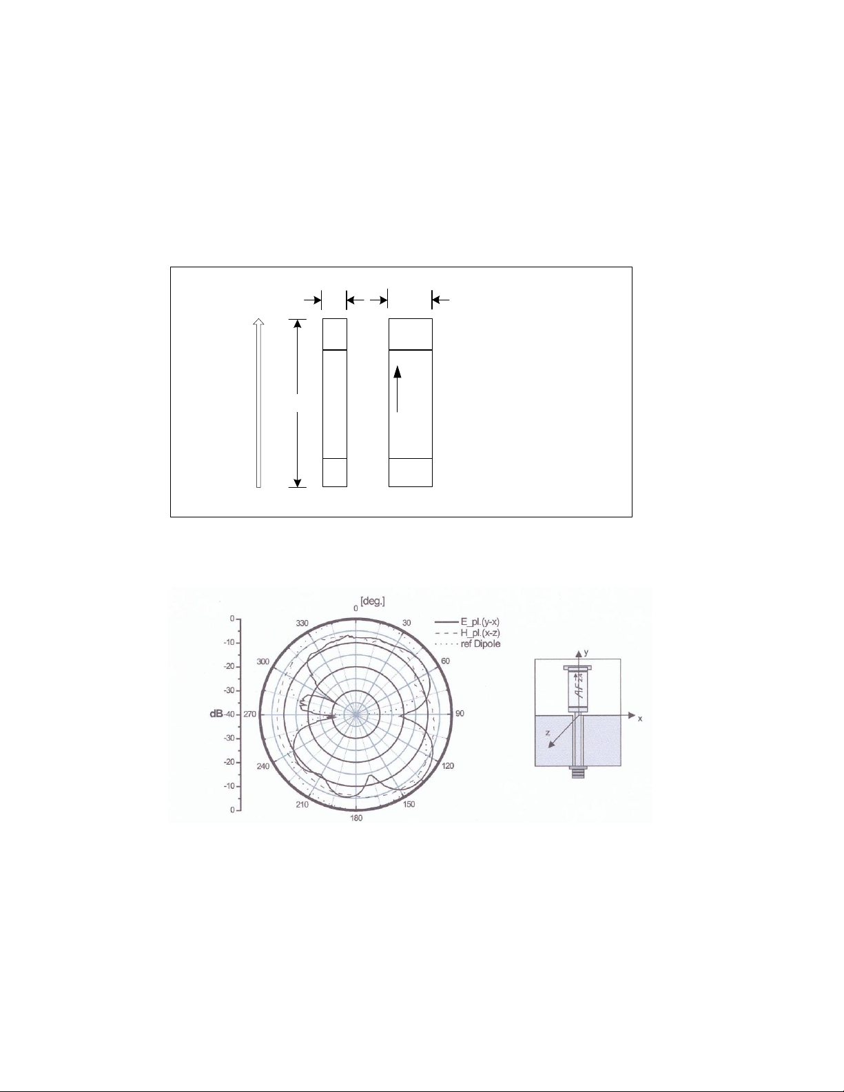
The SLN has an embedded dipole antenna for the transmission and reception of
Bluetooth Radio-Frequency (RF) Signals. The antenna is an Antenna Factor chip
antenna, ANT-2.45-CHP-x. The antenna physical dimensions are shown in Figure 3.
The radiation pattern is shown in Figure 4.
The antenna has linear polarization, a 50 ohm input impedance, and is capable of
transmitting a continuous output of ≥3 watts.
Figure 3. SLN Antenna Dimensions
Figure 4. Antenna Radiation Pattern
SiteWERX 1June 09
Page 8

SiteWERX User Manual WirelessWerx
6
2.1.5 Development/Programming Interface
The SLN is programmed using a dedicated four-wire serial peripheral interface (SPI).
The SPI is also used for real-time debugging / development, and is connected to a
PC parallel port via connector and cable assembly made by WirelessWERX.
2.1.6 Status Indicators
The SLN has two LED status indicators. One RED LED is illuminated when power is
on. A second GREEN LED is illuminated when the Network status is positive.
2.1.7 Enclosure
The SLN assembly consists of a PCB mounted in an enclosure 3.0” x 2.5” x 1.5’’.
The enclosure material is Polylac-747, an ABS. The enclosure wall thickness is as
thin as practical to minimize Radio Frequency signal attenuation and reflections.
2.1.8 Environment
The SLN allowable environments for operating and storage are as follows:
Operating Temperature -40 to +70 C
Storage Temperature -40 to +85 C
Operating Humidity 5% to 80% RH, non-condensing
SiteWERX 1June 09
Page 9

SiteWERX User Manual WirelessWerx
7
3. Constraints
This device complies with Part 15 of the FCC Rules.
Operation is subject to the following two conditions:
(1) This device may not cause harmful interference and
(2) this device must accept any interference received, including interference that
may cause undesired operation.
Instruction to the User
This equipment has been tested and found to comply with the limits for a class B
digital device, pursuant to part 15 of the FCC Rules. These limits are designed to
provide reasonable protection against harmful interference in a residential installation.
This equipment generates, uses and can radiate radio frequency energy and if not
installed and used in accordance with the instructions, may cause harmful
interference to radio communications. However, there is no guarantee that
interference will not occur in a particular installation. If this equipment does cause
harmful interference to radio or television reception, which can be determined by
turning the equipment off and on, the user is encouraged to try to correct the
interference by one or more of the following measures:
* Reorient or relocate the receiving antenna.
* Increase the separation between the equipment and receiver.
* Connect the equipment into an outlet on a circuit different from that to which the
receiver is connected.
* Consult the dealer or an experienced radio/TV technician for help.
Operation with non-approved equipment is likely to result in interference to radio and TV
reception. The user is cautioned that changes and modifications made to the equipment
without the approval of manufacturer could void the user's authority to operate this
equipment.
4. Reference Documentation
Bluetooth 2.0 + Enhanced Data Rate (EDR)
BlueCore4-External DataBook
Antenna Factor Antenna, ANT-2.45-CHP-x Datasheet
Case Material Datasheet, Polylac-747
4.1 Acronyms/Abbreviations
AC Alternating Current
dBi Decibels referenced to an isotropic radiator operating at the same
frequency
SiteWERX 1June 09
Page 10

SiteWERX User Manual WirelessWerx
8
dBm Decibels referenced to One milliWatt
DC direct current
EDR Enhanced Data Rate
GPS Global Positioning System
I/O Input /Output
mA milliAmperes
Mbps Megabits per second
PCB Printed Circuit Board
SBS SiteWERX Base Station
SLN SiteWERX Location Node
SPI Serial Peripheral Interface
UART Universal Asynchronous Receiver/Transmitter
USB Universal Serial Bus
VAC Volts, Alternating Current
VDC Volts, Direct Current
SiteWERX 1June 09
 Loading...