

Page 1

User Manual
SiteWERX Base Station, Wired
1 June 2009
Page 2

SiteWERX User Manual WirelessWERX
Table of Contents
1. Scope ...........................................................................................................1
1.1 Safety Instructions .......................................................................................................... 1
1.2 Contact Information......................................................................................................... 1
2. Description ..................................................................................................2
2.1 SiteWERX Base Station .................................................................................................. 2
2.2 Architecture ...................................................................................................................... 3
2.2.1 Bluetooth Module .................................................................................................... 3
2.2.2 LAN module ............................................................................................................ 4
2.2.3 Voltage and Operating Current ............................................................................... 4
2.2.4 Antenna ................................................................................................................... 4
2.2.5 Power Supply .......................................................................................................... 6
2.2.6 Power-On Indicator ................................................................................................. 6
2.2.7 Development/Programming Interface ..................................................................... 6
2.3 Construction and Packaging .......................................................................................... 6
2.4 Environment ..................................................................................................................... 7
3. Constraints ..................................................................................................7
4. Declaration of Conformity ..........................................................................8
5. Reference Documentation .........................................................................9
5.1 Acronyms/Abbreviations ................................................................................................ 9
Table of Figures
Figure 1 SiteWERX Location System ................................................................................................... 2
Figure 2. SiteWERX Base Station Block Diagram .............................................................................. 3
Figure 3 SBS Antenna Pattern .............................................................................................................. 5
SiteWERX ii 1June09
Page 3

SiteWERX User Manual WirelessWERX
1
1. Scope
This document provides user information for the SiteWERX Base Station.
Information is included regarding safety, technical features, installation, and operating
constraints
1.1 Safety Instructions
a. Read the manual carefully before use.
b. The Base Station shall be installed according to the installation
instructions.
c. The Base Station is for indoor use only.
d. Ensure that power is OFF during installation procedures.
e. All maintenance and servicing should be performed or supervised by qualified
service personnel.
f. To satisfy RF exposure requirements, this device and its antenna must operate
with a separation distance of at least 20 cm from all persons and must not be colocated or operating in conjunction with any other antenna or transmitter.
1.2 Contact Information
This product is manufactured by:
WirelessWERX, Inc.
100 Chaparral Court, Suite 100
Anaheim, CA 92808
Phone: 714-685-9776
Fax: 714-685-9270
SiteWERX 1June09
Page 4
SiteWERX User Manual WirelessWERX
2
SiteWERX
Management
Console
PC
LAN
SiteWERX Base Station SLN1
Bluetooth Bluetooth
SLN 2
SLN 3
Bluetooth
Cell
Phone
SMC
Bluetooth
2. Description
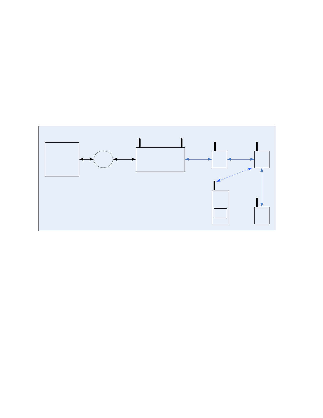
The SiteWERX Location system consists of System Management software residing
on a networked PC, a SiteWERX Base Station (SBS), and one or more SiteWERX
Location Nodes (SLN’s).
The SBS and SLN’s form a communication chain (scatternet) using Bluetooth radios.
The SBS maintains a communication link with the Management Console, allowing
the system to be managed by a PC. Mobile devices, such as cell phones and PDAs,
running the SiteWERX Mobile Client (SMC) software are able to communicate with
an SLN to receive location and real-time messages, reference Figure 1.
Figure 1 SiteWERX Location System
2.1 SiteWERX Base Station
The SBS has the following functional capabilities:
a) Operate as a Bluetooth device in accordance with the Bluetooth 2.0 + EDR
b) Establish wireless links with other Bluetooth devices in proximities of 1 to 10
meters
c) Transmit area-specific information to other Bluetooth devices in support of
precision location
d) Transmit information to, and receive information from other Bluetooth devices in support of
system administration, status and diagnostics
e) Transmit Real-Time Alerts
f) Establish Ethernet link with System Management Console
SiteWERX 1June09
Page 5
SiteWERX User Manual WirelessWERX
3
Bluetooth
Module
Input Voltage
3.3 VDC
LAN Interface
Controller & Memory
Transceiver
Controller & Memory
Link with Location Nodes
Development/
Programming Interface
Base Station
Module
System Controller
2.2 Architecture
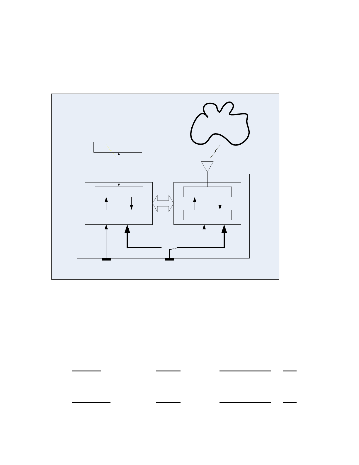
The SBS consists of a Bluetooth Module for Bluetooth operations, a Bluetooth
antenna, a LAN module, and Ethernet interface for communications with the
SiteWERX System Controller. A functional block diagram of the SiteWERX Base
Station is shown in Figure 2
Figure 2. SiteWERX Base Station Block Diagram
2.2.1 Bluetooth Module
The SLN has a CSR BlueCore4-External radio to provide the operating parameters
and protocols required by the Bluetooth 2.0 + EDR Core Specification.
2.2.1.1 Radio Characteristics, Basic Data Rate
Receiver Typical Bluetooth Spec Unit
Sensitivity @ 0.1% BER - 83 ≤ - 70 dBm
Transmitter Typical Bluetooth Spec Unit
Max RF Transmit Power + 4 - 6 to + 4 dBm
SiteWERX 1June09
Page 6

SiteWERX User Manual WirelessWERX
4
2.2.1.2 Radio Characteristics, Enhanced Data Rate
Receiver Typical Bluetooth Spec Unit
Sensitivity @ 0.1% BER - 83 ≤ - 70 dBm
Transmitter Typical Bluetooth Spec Unit
Max RF Transmit Power + 4 - 6 to + 4 dBm
2.2.2 LAN module
The SBS LAN module manages the Ethernet interface with the System Controller.
SBS Data Rates:
1, 2, 5.5, 11, 6, 9, 12, 18, 24, 36, 48, 54 Mbps
The SBS LAN module connects to the Ethernet through a RJ45 connector.
2.2.3 Voltage and Operating Current
The SBS module operates with an input of 3.3 VDC and a max current ≤ 700 mA .
2.2.4 Antenna
The SBS Module has an antenna for the transmission and reception of Bluetooth
Radio-Frequency (RF) Signals. The antenna shall be a Roving Networks dipole
antenna, ANT-2.4-CW_RCT-SS, or equivalent.
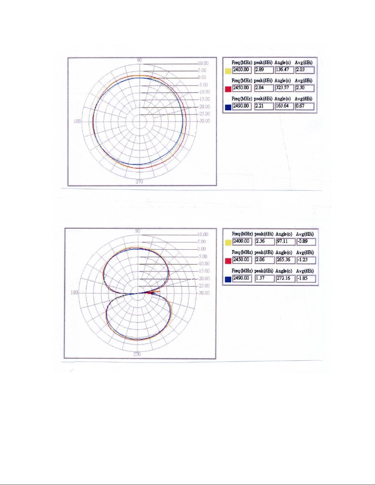
The SBS antenna has a nominal impedance of 50 ohms, linear polarization, and a
near omni-directional radiation pattern in azimuth. The maximum gain is 2.89dBi,
reference Figure 3.
The SBS antenna is capable of transmitting a constant 1.0 watt.
The SBS antenna has a right angle, reverse polarity SMA connector.
The SBS antenna is adjustable and normally operates with the primary axis aligned
with the local vertical.
SiteWERX 1June09
Page 7
SiteWERX User Manual WirelessWERX
5
Figure 3 SBS Antenna Pattern
SiteWERX 1June09
Page 8

SiteWERX User Manual WirelessWERX
6
2.2.5 Power Supply
The SBS module operates from an external AC/DC power supply to provide a
regulated DC voltage of 3.3 VDC at 2.18 Amps, and consumes a maximum of 7.2
Watts.
2.2.6 Power-On Indicator
The SBS has a RED LED indicator that is illuminated when power is enabled.
2.2.7 Development/Programming Interface
The SBS has a four-wire serial peripheral interface (SPI). The SPI is used for realtime debugging / development, and is connected to a PC parallel port via connector
and cable assembly made by WirelessWERX.
The development / programming interface is designed to permit the following
connections:
PC connect to Ethernet module only
PC connect to Bluetooth module only
Bluetooth module to Ethernet module, No connection to PC
2.3 Construction and Packaging
The SBS modules, and related circuit elements are assembled on a single PCB. The
PCB shall be enclosed in a Bud Industries Plastibox, PT-11754, with the following
(nominal) dimensions:
Length 4 inches
Width 5.5 inches
Height 1.5 inches
The SBS Bluetooth module RF output is brought to the edge of the PCB and
terminated in bulkhead type, SMA connector that penetrates the enclosure and
permits the connect/disconnect of the SBS antenna external to the enclosure.
SiteWERX 1June09
Page 9

SiteWERX User Manual WirelessWERX
7
2.4 Environment
The SiteWERX allowable environments for SBS operating and storage are as follows:
Operating Temperature -40 to +70 C
Storage Temperature -40 to +85 C
Operating Humidity 5% to 80% RH, non-condensing
3. Constraints
This equipment has been tested and found to comply with the limits for a class B
digital device, pursuant to part 15 of the FCC Rules. These limits are designed to
provide reasonable protection against harmful interference in a residential installation.
This equipment generates, uses and can radiate radio frequency energy and if not
installed and used in accordance with the instructions, may cause harmful
interference to radio communications. However, there is no guarantee that
interference will not occur in a particular installation. If this equipment does cause
harmful interference to radio or television reception, which can be determined by
turning the equipment off and on, the user is encouraged to try to correct the
interference by one or more of the following measures:
* Reorient or relocate the receiving antenna.
* Increase the separation between the equipment and receiver.
* Connect the equipment into an outlet on a circuit different from that to which the
receiver is connected.
* Consult the dealer or an experienced radio/TV technician for help.
Operation with non-approved equipment is likely to result in interference to radio and TV
reception. The user is cautioned that changes and modifications made to the equipment
without the approval of manufacturer could void the user's authority to operate this
equipment.
SiteWERX 1June09
Page 10

SiteWERX User Manual WirelessWERX
8
TRADE NAME
Network Bridge
MODEL NUMBER
SBS03
RESPONSIBLE PARTY (IN USA)
WirelessWERX, Inc.
ADDRESS
100 S. Chaparral Court, Suite 100: Anaheim, CA
TELEPHONE
714-685-9776
4. Declaration of Conformity
This equipment has been tested and found to comply with the limits for a class B digital device,
pursuant to part 15 of the FCC Rules. These limits are designed to provide reasonable protection
against harmful interference in a residential installation. This equipment generates, uses and can
radiate radio frequency energy and if not installed and used in accordance with the instructions, may
cause harmful interference to radio communications. However, there is no guarantee that interference
will not occur in a particular installation.
If the unit does cause harmful interference to radio or television reception, please refer to your user
manual for instructions on correcting the problem.
SiteWERX 1June09
Page 11

SiteWERX User Manual WirelessWERX
9
5. Reference Documentation
Bluetooth 2.0 + Enhanced Data Rate (EDR)
BlueCore4-External DataBook
Dipole Antenna Datasheet
5.1 Acronyms/Abbreviations
AC Alternating Current
BIST Built In Self Test
CM Cellular Module
dBi Decibels referenced to an isotropic radiator operating at the same
frequency
dBm Decibels referenced to One milliWatt
DC direct current
EDR Enhanced Data Rate
EEPROM Electrically Erasable Programmable Read Only Memory
GPS Global Positioning System
I/O Input /Output
mA milliAmperes
PCB Printed Circuit Board
SBS SiteWERX Base Station
SLN SiteWERX Location Node
SPS SiteWERX Power Supply
UART Universal Asynchronous Receiver/Transmitter
USB Universal Serial Bus
VAC Volts, Alternating Current
VDC Volts, Direct Current
SiteWERX 1June09
 Loading...