

Page 1

RT System 2
Deployment Guide
April 15, 2014
Part Number: 90-0069
R01.i
Page 2

© 2010-2014 Wireless Seismic, Inc. All rights reserved.
All other brands, company names, product names, trademarks or service marks referenced in this material are the
property of their respective owners, who may or may not be affiliated with, connected to, or sponsored by Wireless
Seismic, Inc.
Wireless Seismic, Inc.'s trademarks, registered trademarks or trade dress may not be used in connection with any
product or service that is not the property of Wireless Seismic, Inc., in any manner that is likely to cause confusion
among customers, or in any manner that disparages or discredits Wireless Seismic, Inc. The products and services
described in this material may not be available in all regions.
All information supplied in this document regarding weights, sizes, performance, functionality and other technical
information of any kind is approximate and shall be taken as generally representing our products. We may modify our
products, discontinue products or add new products at any time and without providing an update to this document.
NOTHING CONTAINED IN THIS DOCUMENT SHALL BE CONSIDERED A REPRESENTATION OR WARRANTY MADE BY
WIRELESS SEISMIC, INC. (“WIRELESS SEISMIC”) CONCERNING ANY PRODUCT DESCRIBED HEREIN, OR OTHERWISE.
EXCEPT FOR THE WARRANTIES THAT MAY BE PROVIDED IN A SEPARATE AGREEMENT BETWEEN YOU AND WIRELESS
SEISMIC, WIRELESS SEISMIC MAKES NO REPRESENTATION OR WARRANTY OF ANY KIND AND NO WARRANTY,
CONDITION OR REPRESENTATION, WHETHER EXPRESS, IMPLIED, ORAL OR STATUTORY, IS PROVIDED TO YOU OR
ANY THIRD PARTY. WITHOUT LIMITING THE FOREGOING, WIRELESS SEISMIC EXPRESS EXCLUDES AND DISCLAIMS
ANY WARRANTY, CONDITION OR REPRESENTATION: (1) OF MERCHANTABILITY, FITNESS FOR A PARTICULAR
PURPOSE, TITLE, SATISFACTORY QUALITY, OR ARISING FROM A COURSE OF DEALING, USAGE, OR TRADE PRACTICE;
(2) THAT ANY PRODUCTS (INCLUDING SOFTWARE) WILL BE FREE FROM INFRINGEMENT OR VIOLATION OF ANY
RIGHTS, INCLUDING INTELLECTUAL PROPERTY RIGHTS, OF THIRD PARTIES; OR (3) THAT THE OPERATION OF ANY
PRODUCT (INCLUDING SOFTWARE) WILL BE UNINTERRUPTED OR ERROR FREE. THIS DISCLAIMER AND EXCLUSION
SHALL APPLY EVEN IF THE EXPRESS WARRANTIES HEREIN FAIL OF THEIR ESSENTIAL PURPOSE.
To order additional copies of this document, send an email to your sales representative requesting the
following:
i Part Number: 90-0069-PDF
i Part Number: 90-0069-Paper
Corporate Headquarters: 13100 Southwest Freeway, Suite 150 x Sugar Land, TX 77478 USA x 832-532-5080
Regional Office: 1172 West Century Drive, Suite 200
[email protected]
x www.wirelessseismic.com
Real Time Matters
x Louisville, CO 80027 USA x 720-242-9916
Page 3

Table of Contents
1.1. Overview . . . . . . . . . . . . . . . . . . . . . . . . . . . . . . . . . . . . . . . . . . . . . . . . . . . . . . 10
1.1 About this Guide . . . . . . . . . . . . . . . . . . . . . . . . . . . . . . . . . . . . . . . . . . . 10
1.2 Who Should Use this Guide . . . . . . . . . . . . . . . . . . . . . . . . . . . . . . . . . . . . 10
1.3 Related Documents . . . . . . . . . . . . . . . . . . . . . . . . . . . . . . . . . . . . . . . . . 10
1.4 Getting Help . . . . . . . . . . . . . . . . . . . . . . . . . . . . . . . . . . . . . . . . . . . . . . 10
2.2. Layout. . . . . . . . . . . . . . . . . . . . . . . . . . . . . . . . . . . . . . . . . . . . . . . . . . . . . . . . 11
2.1 Prerequisites . . . . . . . . . . . . . . . . . . . . . . . . . . . . . . . . . . . . . . . . . . . . . . 11
2.2 Getting Ready . . . . . . . . . . . . . . . . . . . . . . . . . . . . . . . . . . . . . . . . . . . . . 11
2.3 Preparing the Equipment. . . . . . . . . . . . . . . . . . . . . . . . . . . . . . . . . . . . . . 12
2.4 Laying Out the Equipment. . . . . . . . . . . . . . . . . . . . . . . . . . . . . . . . . . . . . 12
2.4.1 Prerequisites . . . . . . . . . . . . . . . . . . . . . . . . . . . . . . . . . . . . . . . . . . 14
2.4.2 Assembling the Ground Equipment . . . . . . . . . . . . . . . . . . . . . . . . . . . 16
2.4.3 Placing the WRU in the Field. . . . . . . . . . . . . . . . . . . . . . . . . . . . . . . . 19
2.4.4 Placing the LIU in the Field. . . . . . . . . . . . . . . . . . . . . . . . . . . . . . . . . 22
2.5 WRU Anchor Plate . . . . . . . . . . . . . . . . . . . . . . . . . . . . . . . . . . . . . . . . . . 22
3.3. Backhaul . . . . . . . . . . . . . . . . . . . . . . . . . . . . . . . . . . . . . . . . . . . . . . . . . . . . . . 26
3.1 Overview . . . . . . . . . . . . . . . . . . . . . . . . . . . . . . . . . . . . . . . . . . . . . . . . 26
3.2 Backhaul Components . . . . . . . . . . . . . . . . . . . . . . . . . . . . . . . . . . . . . . . 31
3.2.1 LIU . . . . . . . . . . . . . . . . . . . . . . . . . . . . . . . . . . . . . . . . . . . . . . . . . 38
3.2.2 LIU Battery . . . . . . . . . . . . . . . . . . . . . . . . . . . . . . . . . . . . . . . . . . . 39
3.2.3 LIU and WRU Antennas . . . . . . . . . . . . . . . . . . . . . . . . . . . . . . . . . . . 39
3.2.4 Line Radios . . . . . . . . . . . . . . . . . . . . . . . . . . . . . . . . . . . . . . . . . . . 39
3.2.5 Recorder Radio. . . . . . . . . . . . . . . . . . . . . . . . . . . . . . . . . . . . . . . . . 42
3.2.6 Radio Antennas . . . . . . . . . . . . . . . . . . . . . . . . . . . . . . . . . . . . . . . . 44
3.2.7 Surge Protector Box . . . . . . . . . . . . . . . . . . . . . . . . . . . . . . . . . . . . . 44
3.2.8 Cable Assemblies . . . . . . . . . . . . . . . . . . . . . . . . . . . . . . . . . . . . . . . 45
3.2.9 Mast and Base . . . . . . . . . . . . . . . . . . . . . . . . . . . . . . . . . . . . . . . . . 49
3.2.9.1 Telescoping Mast. . . . . . . . . . . . . . . . . . . . . . . . . . . . . . . . . . . . 49
3.2.9.2 Base . . . . . . . . . . . . . . . . . . . . . . . . . . . . . . . . . . . . . . . . . . . . 49
3.3 Setting up the Backhaul . . . . . . . . . . . . . . . . . . . . . . . . . . . . . . . . . . . . . . 50
4.4. Point-to-Point Backhaul . . . . . . . . . . . . . . . . . . . . . . . . . . . . . . . . . . . . . . . . . . 65
4.1 Overview . . . . . . . . . . . . . . . . . . . . . . . . . . . . . . . . . . . . . . . . . . . . . . . . 65
4.2 Preparation . . . . . . . . . . . . . . . . . . . . . . . . . . . . . . . . . . . . . . . . . . . . . . . 70
4.3 Create Plan and Map . . . . . . . . . . . . . . . . . . . . . . . . . . . . . . . . . . . . . . . . 76
4.4 Install and Troubleshoot . . . . . . . . . . . . . . . . . . . . . . . . . . . . . . . . . . . . . . 77
4.5 Final Communication Test . . . . . . . . . . . . . . . . . . . . . . . . . . . . . . . . . . . . . 80
4.6 Rolling the Backhaul. . . . . . . . . . . . . . . . . . . . . . . . . . . . . . . . . . . . . . . . . 86
4.7 Replacing a Radio. . . . . . . . . . . . . . . . . . . . . . . . . . . . . . . . . . . . . . . . . . . 90
4.8 Upload New Firmware. . . . . . . . . . . . . . . . . . . . . . . . . . . . . . . . . . . . . . . . 90
4.9 Unzipping the Configuration Files. . . . . . . . . . . . . . . . . . . . . . . . . . . . . . . . 91
4.10 Connecting to the Recording Truck. . . . . . . . . . . . . . . . . . . . . . . . . . . . . . 92
5.5. Point-to-Multipoint Backhaul . . . . . . . . . . . . . . . . . . . . . . . . . . . . . . . . . . . . . . 98
RT System 2 v2.3 3 Deployment Guide R01.i
© 2010-2014 Wireless Seismic, Inc. All rights reserved.
Page 4

Table of Contents
5.1 Overview . . . . . . . . . . . . . . . . . . . . . . . . . . . . . . . . . . . . . . . . . . . . . . . . .98
5.2 Preparation. . . . . . . . . . . . . . . . . . . . . . . . . . . . . . . . . . . . . . . . . . . . . . .104
5.3 Create Plan and Map . . . . . . . . . . . . . . . . . . . . . . . . . . . . . . . . . . . . . . . .111
5.4 Install and Troubleshoot. . . . . . . . . . . . . . . . . . . . . . . . . . . . . . . . . . . . . .115
5.4.1 Using one Recorder Radio . . . . . . . . . . . . . . . . . . . . . . . . . . . . . . . . .117
5.4.2 Using a Redundant Recorder Radio. . . . . . . . . . . . . . . . . . . . . . . . . . .118
5.4.3 Using a Custom Configuration . . . . . . . . . . . . . . . . . . . . . . . . . . . . . .119
5.5 Final Communication Test. . . . . . . . . . . . . . . . . . . . . . . . . . . . . . . . . . . . .119
5.6 Replacing a Radio . . . . . . . . . . . . . . . . . . . . . . . . . . . . . . . . . . . . . . . . . .1 27
5.7 Upload New Firmware . . . . . . . . . . . . . . . . . . . . . . . . . . . . . . . . . . . . . . .128
5.8 Unzipping the Configuration Files. . . . . . . . . . . . . . . . . . . . . . . . . . . . . . . .128
5.9 Connecting to the Recording Truck . . . . . . . . . . . . . . . . . . . . . . . . . . . . . .129
6.6. Demobilization . . . . . . . . . . . . . . . . . . . . . . . . . . . . . . . . . . . . . . . . . . . . . . . . .135
6.1 Overview . . . . . . . . . . . . . . . . . . . . . . . . . . . . . . . . . . . . . . . . . . . . . . . .135
6.2 Removing the WRU from the Field . . . . . . . . . . . . . . . . . . . . . . . . . . . . . . .135
6.3 Disassemble the WRU . . . . . . . . . . . . . . . . . . . . . . . . . . . . . . . . . . . . . . .136
7.7. Batteries. . . . . . . . . . . . . . . . . . . . . . . . . . . . . . . . . . . . . . . . . . . . . . . . . . . . . .138
7.1 Lithium Ion Batteries . . . . . . . . . . . . . . . . . . . . . . . . . . . . . . . . . . . . . . . .138
7.1.1 Specifications. . . . . . . . . . . . . . . . . . . . . . . . . . . . . . . . . . . . . . . . . .138
7.1.2 Handling and Safety Guidelines . . . . . . . . . . . . . . . . . . . . . . . . . . . . .139
7.1.3 Transportation . . . . . . . . . . . . . . . . . . . . . . . . . . . . . . . . . . . . . . . . .140
7.1.4 Storage. . . . . . . . . . . . . . . . . . . . . . . . . . . . . . . . . . . . . . . . . . . . . .141
7.2 Charging Lithium Ion Batteries . . . . . . . . . . . . . . . . . . . . . . . . . . . . . . . . .141
7.2.1 Charging Precautions . . . . . . . . . . . . . . . . . . . . . . . . . . . . . . . . . . . .141
7.2.2 Battery Charger . . . . . . . . . . . . . . . . . . . . . . . . . . . . . . . . . . . . . . . .1 42
A.A. Legal Information . . . . . . . . . . . . . . . . . . . . . . . . . . . . . . . . . . . . . . . . . . . . . .144
A.1 FCC Rules and Regulations Compliance . . . . . . . . . . . . . . . . . . . . . . . . . . .144
A.2 Industry Canada Compliance . . . . . . . . . . . . . . . . . . . . . . . . . . . . . . . . . .146
A.3 CE Compliance . . . . . . . . . . . . . . . . . . . . . . . . . . . . . . . . . . . . . . . . . . . .146
A.4 Australian Compliance . . . . . . . . . . . . . . . . . . . . . . . . . . . . . . . . . . . . . . .146
B.B. WRU and LIU Specifications . . . . . . . . . . . . . . . . . . . . . . . . . . . . . . . . . . . . . . .147
B.1 WRU Specifications . . . . . . . . . . . . . . . . . . . . . . . . . . . . . . . . . . . . . . . . .147
B.2 LIU Specifications . . . . . . . . . . . . . . . . . . . . . . . . . . . . . . . . . . . . . . . . . .148
C.C. Radio Specifications . . . . . . . . . . . . . . . . . . . . . . . . . . . . . . . . . . . . . . . . . . . . .149
C.1 Antenna Specifications. . . . . . . . . . . . . . . . . . . . . . . . . . . . . . . . . . . . . . .149
C.1.1 Bullet Line Station Antenna . . . . . . . . . . . . . . . . . . . . . . . . . . . . . . . .149
C.1.2 Rocket Recorder Antenna . . . . . . . . . . . . . . . . . . . . . . . . . . . . . . . . .152
C.1.3 NanoStation Recorder/Line Station Antenna . . . . . . . . . . . . . . . . . . . .155
C.2 Radio Specifications. . . . . . . . . . . . . . . . . . . . . . . . . . . . . . . . . . . . . . . . .156
C.2.1 Bullet Line Station Radios . . . . . . . . . . . . . . . . . . . . . . . . . . . . . . . . .157
C.2.2 Rocket Recorder Radios . . . . . . . . . . . . . . . . . . . . . . . . . . . . . . . . . .159
C.2.3 NanoStation Recorder/Line Station Radios. . . . . . . . . . . . . . . . . . . . . .160
D.D. LED Indicators . . . . . . . . . . . . . . . . . . . . . . . . . . . . . . . . . . . . . . . . . . . . . . . . .163
4 RT System 2 v2.3 Deployment Guide R01.i
© 2010-2014 Wireless Seismic, Inc. All rights reserved.
Page 5

Table of Contents
D.1 WRU Undeployed. . . . . . . . . . . . . . . . . . . . . . . . . . . . . . . . . . . . . . . . . . 163
D.2 WRU Deploying . . . . . . . . . . . . . . . . . . . . . . . . . . . . . . . . . . . . . . . . . . . 165
D.3 WRU Deployed . . . . . . . . . . . . . . . . . . . . . . . . . . . . . . . . . . . . . . . . . . . 172
D.4 LIU Power-On . . . . . . . . . . . . . . . . . . . . . . . . . . . . . . . . . . . . . . . . . . . . 175
D.5 LIU Normal Operation . . . . . . . . . . . . . . . . . . . . . . . . . . . . . . . . . . . . . . 176
D.6 Firmware Upgrade . . . . . . . . . . . . . . . . . . . . . . . . . . . . . . . . . . . . . . . . . 180
E.E. Weighted Base . . . . . . . . . . . . . . . . . . . . . . . . . . . . . . . . . . . . . . . . . . . . . . . . 182
E.1 Specifications . . . . . . . . . . . . . . . . . . . . . . . . . . . . . . . . . . . . . . . . . . . . 182
E.2 Hardware Supplied. . . . . . . . . . . . . . . . . . . . . . . . . . . . . . . . . . . . . . . . . 183
E.3 Assembly Instructions. . . . . . . . . . . . . . . . . . . . . . . . . . . . . . . . . . . . . . . 183
F.F. Using a Compass . . . . . . . . . . . . . . . . . . . . . . . . . . . . . . . . . . . . . . . . . . . . . . . 184
G.G. Rope Knot. . . . . . . . . . . . . . . . . . . . . . . . . . . . . . . . . . . . . . . . . . . . . . . . . . . . 188
H.H. Country Codes . . . . . . . . . . . . . . . . . . . . . . . . . . . . . . . . . . . . . . . . . . . . . . . . 189
I.I. Français . . . . . . . . . . . . . . . . . . . . . . . . . . . . . . . . . . . . . . . . . . . . . . . . . . . . . . 194
I.1 Batteries . . . . . . . . . . . . . . . . . . . . . . . . . . . . . . . . . . . . . . . . . . . . . . . . 194
I.1.1 Batteries au lithium-ion . . . . . . . . . . . . . . . . . . . . . . . . . . . . . . . . . . 194
I.1.1.1 Spécifications . . . . . . . . . . . . . . . . . . . . . . . . . . . . . . . . . . . . . 194
I.1.1.2 Directives en matière de manipulation et de sécurité . . . . . . . . . . 195
I.1.1.3 Transport . . . . . . . . . . . . . . . . . . . . . . . . . . . . . . . . . . . . . . . . 196
I.1.1.4 Entreposage . . . . . . . . . . . . . . . . . . . . . . . . . . . . . . . . . . . . . . 198
I.1.2 Chargement des batteries au lithium-ion . . . . . . . . . . . . . . . . . . . . . . 198
I.1.2.1 Précautions de chargement . . . . . . . . . . . . . . . . . . . . . . . . . . . . 198
I.1.2.2 Chargeur de batterie . . . . . . . . . . . . . . . . . . . . . . . . . . . . . . . . 199
I.2 l'information juridique. . . . . . . . . . . . . . . . . . . . . . . . . . . . . . . . . . . . . . . 200
I.2.1 Conformité avec les règles et règlements de la FCC. . . . . . . . . . . . . . . 200
I.2.2 Industrie Canada Conformité . . . . . . . . . . . . . . . . . . . . . . . . . . . . . . 201
I.2.3 Acquiescement de CE. . . . . . . . . . . . . . . . . . . . . . . . . . . . . . . . . . . . 202
Index . . . . . . . . . . . . . . . . . . . . . . . . . . . . . . . . . . . . . . . . . . . . . . . . . . . . . . . . . . . 203
R01.i RT System 2 v2.3 Deployment Guide 5
© 2010-2014 Wireless Seismic, Inc. All rights reserved.
Page 6

List of Figures
List of Figures
Figure 2–1 WRU .......................................................................................................... 12
Figure 2–2 WRU with Geophone..................................................................................... 13
Figure 2–3 LIU ............................................................................................................ 14
Figure 2–4 Assembling WRUs........................................................................................ 15
Figure 2–5 Battery Latch .............................................................................................. 17
Figure 2–6 Installing the Battery....................................................................................17
Figure 2–7 Installing the Geophone................................................................................ 18
Figure 2–8 Antenna Extender (65-0091)......................................................................... 18
Figure 2–9 Antenna with Spring Relief............................................................................ 19
Figure 2–10 Power on the Unit........................................................................................ 20
Figure 2–11 Place the Unit..............................................................................................21
Figure 2–12 Geophone Self-Test Failure ........................................................................... 22
Figure 2–13 Attaching the Anchor Plate to the WRU ...........................................................23
Figure 2–14 Anchor Plate and WRU Alignment...................................................................23
Figure 2–15 Anchor Plate at WRU Geophone End...............................................................24
Figure 2–16 Anchor Plate Bracket....................................................................................24
Figure 2–17 Anchor Bracket Screws .................................................. ............................... 24
Figure 2–18 Anchor Plate Attached to WRU....................................................................... 25
Figure 2–19 WRU Anchored with Anchor Plate...................................................................25
Figure 3–1 Point-to-Point Single Backhaul Data Direction..................................................28
Figure 3–2 Point-to-Point Dual Backhaul Da ta Direction ....... ................................. ............ 29
Figure 3–3 Point-to-Multipoint Backhaul Data Direction..................................................... 30
Figure 3–4 Line Station Backhaul Components................................................................. 35
Figure 3–5 Recorder Backhaul Components...... ................................................. .............. 36
Figure 3–6 Recorder/Line NanoStation Backhaul Components............................................ 37
Figure 3–7 Line Interface Unit (LIU) ....................................................................... ........ 38
Figure 3–8 Line Radio and Antennas, Bullet.................................. ................................... 40
Figure 3–9 Line Radio, NanoStation................................. ............................................... 41
Figure 3–10 Bullet Radio Case (70-0138)..........................................................................41
Figure 3–11 NanoStation Radio Case (70-0176) ................................................................ 42
Figure 3–12 Recorder Radio............................................................................................ 43
Figure 3–13 Surge Protector Connections .........................................................................44
Figure 3–14 Cable, LIU to Battery (60-0034) ....................................................................45
Figure 3–15 Cable, LIU to NanoStation Radio (60-0036).....................................................46
Figure 3–16 Cable, LIU-to-PC (60-0039) .......................................................................... 47
Figure 3–17 Cable, Ethernet, 3 ft Shielded (65-0104)......................................................... 47
Figure 3–18 Cable, Armored Ethernet, 10 ft (60-0053).......................................................47
Figure 3–19 Cable, RF Extender, 10 ft (65-0103)....................................... ........................ 48
Figure 3–20 Media Converter (60-0017)..................................................................... ...... 48
Figure 3–21 Cable, Backhaul Jumper (60-0033) ................................................................ 48
Figure 3–22 Cable, Fiber Optic, Armored, 250 m (60-0026)................................................ 49
Figure 3–23 Mast (55-0050) ...........................................................................................49
Figure 3–24 Base (55-0050)........................................................................................... 50
Figure 4–1 Channel – 80 MHz Wide Frequency Band......................................................... 65
Figure 4–2 Line Station Backhaul...................................................................................66
Figure 4–3 Radio-to-Radio Communication......................................................................68
Figure 4–4 Radio-to-Fiber Communication.......................................................................69
Figure 4–5 Preparation Troubleshooting Flow................................................................... 70
Figure 4–6 Invalid Country Code Error Message...............................................................71
Figure 4–7 Ubiquiti NanoStation Private Network Connection............................................. 72
Figure 4–8 Ubiquiti Discovery Tool Icon.......................................................................... 73
Figure 4–9 Ubiquiti Discovery Window............................................................................74
Figure 4–10 Ubiquiti airOS Login Window..........................................................................74
Figure 4–11 Ubiquiti airOS Window, System Tab.................................................... ............ 75
6 RT System 2 v2.3 Deployment Guide R01.i
© 2010-2014 Wireless Seismic, Inc. All rights reserved.
Page 7

List of Figures
Figure 4–12 Ubiquiti, Upload Configuration File ................................................................. 75
Figure 4–13 Ubiquiti, Apply Configuration Changes ............................................................ 76
Figure 4–14 Create Plan and Map Troubleshooting Flow...................................................... 76
Figure 4–15 Maintain Line-of-Sight .................................................................................. 77
Figure 4–16 Install and Troubleshoot the Radios Flow ........................................................ 78
Figure 4–17 Final Communication Test Flow...................................................................... 81
Figure 4–18 Ubiquiti airOS Tools ..................................................................................... 82
Figure 4–19 Speed Test Window ..................................................................................... 83
Figure 4–20 NanoStation Main Tab .................................................................................. 84
Figure 4–21 NanoStation Radio Shielding and Surge Suppressor.......................................... 85
Figure 4–22 Rolling the Poles Example for 18 Total Poles.................................................... 87
Figure 4–23 Rolling Scheme, 18 Total Poles Example ......................................................... 88
Figure 4–24 Rolling Scheme, 18 Pole Backhaul, 10 Poles in Use........................................... 89
Figure 4–25 Radio Configuration, Updating Firmware ......................................................... 91
Figure 4–26 Connecting the Recording Truck with Fiber...................................................... 92
Figure 4–27 Connecting the Recording Truck with a Pendant Radio Link................................ 93
Figure 4–28 Optimal Angle, Radio Link to Recording Truck . ................................................. 94
Figure 4–29 Connecting the Pendant Radio Link ................................................................ 95
Figure 4–30 Wireless Tab............................................................................................... 97
Figure 5–1 Channel, 80 MHz Wide Frequency Band .......................................................... 98
Figure 5–2 Line Station Mast (Bullet Radio).............. ..................................................... .. 99
Figure 5–3 Recording Truck or Line Station Mast (NanoStation Radio) ...............................100
Figure 5–4 Recording Truck Mast with LIU (Rocket Radio)................................................101
Figure 5–5 Recording Truck Mast without LIU (Rocket Radio) ...........................................102
Figure 5–6 Preparation Troubleshooting Flow .................................................................104
Figure 5–7 Invalid Country Code Error Message..............................................................105
Figure 5–8 Ubiquiti Rocket/Bullet Private Network Connection ..........................................107
Figure 5–9 Ubiquiti Discovery Tool Icon.........................................................................108
Figure 5–10 Ubiquiti Discovery Window...........................................................................109
Figure 5–11 Ubiquiti Login Window.................................................................................109
Figure 5–12 Ubiquiti Rocket/Bullet Window, System Tab....................................................110
Figure 5–13 Upload Configuration File.............................................................................110
Figure 5–14 System Tab, Apply Changes .........................................................................111
Figure 5–15 Create Plan and Map Troubleshooting Flow.....................................................111
Figure 5–16 Maintain Line-of-Sight .................................................................................112
Figure 5–17 Install and Troubleshoot the Radios Flow .......................................................116
Figure 5–18 Final Communication Test Flow.....................................................................120
Figure 5–19 Tools, Speed Test.......................................................................................121
Figure 5–20 Speed Test Window ....................................................................................122
Figure 5–21 Bullet Radio Status Tab ....................................... ........................................124
Figure 5–22 NanoStation Main Tab .................................................................................125
Figure 5–23 Radio/Antenna Shielding..............................................................................126
Figure 5–24 NanoStation Radio Shielding and Surge Suppressor.........................................127
Figure 5–25 Radio Configuration, Updating Firmware ........................................................128
Figure 5–26 Connecting the Recording Truck with Fiber.....................................................130
Figure 5–27 Connecting the Recording Truck with a Pendant Radio Link...............................131
Figure 5–28 Connecting the Pendant Radio Link ...............................................................132
Figure 5–29 Wireless Tab..............................................................................................134
Figure 6–1 Power Off the Unit ............................................................. .........................135
Figure 6–2 Undeployed Unit.........................................................................................136
Figure 6–3 Removing the Battery .......................................................... .......................137
Figure 7–1 Example Battery Shipping Lab el.................... ................................................140
Figure 7–2 Battery Charger..........................................................................................142
Figure 7–3 Serial Number Label and LED Indicator..........................................................143
Figure A–1 CE Mark ....................................................................................................146
Figure C–1 19 dBi Antenna (65-0177) ...........................................................................149
Figure C–2 6 dBi Antenna (65-0179).............................................................................150
Figure C–3 13 dBi Antenna (65-0178) ...........................................................................153
Figure D–1 WRU Down-Tilt Action.................................................................................163
R01.i RT System 2 v2.3 Deployment Guide 7
© 2010-2014 Wireless Seismic, Inc. All rights reserved.
Page 8

List of Figures
Figure D–2 WRU Up-Tilt Action .................................................................................... 163
Figure E–1 Weighted Mast .......................................................................................... 182
Figure E–2 Tripod Assembly, Front View ....................................................................... 183
Figure F–1 Sighting Compass (70-0067)....................................................................... 184
Figure F–2 Declination Indication on Map................................................ ...................... 185
Figure F–3 Compass and Map...................................................................................... 186
Figure F–4 Compass Adjusted for Declination .......................................................... ...... 187
Figure F–5 Compass Adjusted for Declination .......................................................... ...... 187
Figure G–1 Tying the Taut-line Hitch Knot .......................................... ........................... 188
8 RT System 2 v2.3 Deployment Guide R01.i
© 2010-2014 Wireless Seismic, Inc. All rights reserved.
Page 9

List of Tables
List of Tables
Table 3–1 Backhaul Communication Concepts................................................................ 26
Table 3–2 Backhaul Components, LIU, Mast, and Fiber.................................................... 31
Table 3–3 Backhaul Components, Radios........................................................... ............ 32
Table 3–4 Antenna Specifications, WRU/LIU................................................................... 39
Table 3–5 Antenna Specifications, Radios ...................................................................... 44
Table 3–6 Cable Pinout, LIU to Battery (60-0034)........................................................... 45
Table 3–7 Cable Pinout, to NanoStation Radio(60-0036).................................................. 46
Table 3–8 Cable Pinout, LIU-to-PC (60-0039)................................................................. 47
Table 3–9 Cable Pinout, Backhaul Jumper (60-0033)....................................................... 48
Table 3–10 How to Set Up the Backhaul.......................................................................... 50
Table 4–1 Label Nomenclature ..................................................................................... 67
Table 4–2 Ethernet Cable Connections Comparison...................................................... .. . 80
Table 4–3 Pendant Radio Link Elements.. ................................................... .................... 96
Table 5–1 Supported Backhaul Radios............................ ............................... ...............105
Table 5–2 Example File Names....................................................................................106
Table 5–3 Creating a Google Earth Elevation Profile .......................................................113
Table 5–4 Ethernet Cable Connections Comparison...................................................... ..118
Table 5–5 Pendant Radio Link Elements.. ................................................... ...................133
Table 7–1 Lithium Ion Battery Specifications.................................................................138
Table A–1 Antenna Specifications ................................................................................145
Table B–1 WRU Specifications .....................................................................................147
Table B–2 LIU Specifications .......................................................................................148
Table C–1 Antenna Specifications, 6 dBi (65-0179)........................................................150
Table C–2 Antenna Specifications, 13 dBi (65-0177) ......................................................151
Table C–3 Antenna Wind Loading, 13 dBi (65-0177).......................................................152
Table C–4 Antenna Specifications, 13 dBi (65-0178) ......................................................153
Table C–5 NanoStation Integrated Antenna Specifications...............................................155
Table C–6 Bullet Line Station Radio Specifications (56-0019 US, 56-0024 Intl) ..................157
Table C–7 Bullet Line Station Radio Power Specifications (56-0019 US, 56-0024 Intl).........158
Table C–8 Rocket Recorder Radio Specifications (15-0052 US, 15-0054 Intl).....................159
Table C–9 Rocket Recorder Radio Power Specifications (15-0052 US, 15-0054 Intl)............160
Table C–10 NanoStation Radio Specifications (56-0035 US, 56-0032 Intl)...........................160
Table C–11 NanoStation Radio Power Specifications (56-0035 US, 56-0032 Intl) .................161
Table D–1 WRU LED Indications, Undeployed ................................................................164
Table D–2 WRU LED Indications, Undeployed Power-On Sequence....................................165
Table D–3 WRU LED Indications, Deploying Sequence.....................................................166
Table D–4 WRU LED Indications, Deploying Power-On Sequence......................................171
Table D–5 WRU LED Indications, Deployed WRU, No Geophone Tilt ..................................172
Table D–6 WRU LED Indications, Deployed WRU, Geophone Down Tilt ..............................173
Table D–7 WRU LED Indications, Deployed WRU, Geophone Up Tilt ..................................174
Table D–8 LIU LED Indications, Power-On Sequence.......................................................175
Table D–9 LIU LED Status Indications, Normal Mode ......................................................177
Table D–10 LIU LED Error Indications, Normal Mode ........................................................179
Table D–11 WRU and LIU LED Status Indications, Firmware Upgrade..................................180
Table H–1 ISO 3166 Country Codes ..................................... ................................. .......189
R01.i RT System 2 v2.3 Deployment Guide 9
© 2010-2014 Wireless Seismic, Inc. All rights reserved.
Page 10

1.1 About this Guide
This document provides information on how to deploy the RT System 2 in the field. See
the RT System 2 Installation Guide for instructions on setting up the recording truck
equipment and software.
1.2 Who Should Use this Guide
The expected users of this document are as follows:
i Crew (Layout/Troubleshooters)
i Technician (LIU)
i Bosses (Line Crew)
1
1. Overview
1.3 Related Documents
RT System 2-related documents are as follows:
i RT System 2 Documents Guide (90-0026) – Lists all of the RT System 2
documents with a brief description of each.
i RT System 2 Glossary (90-0032) – Lists and defines RT System 2 terms and
acronyms. Includes some general seismic and geologic terms and acronyms.
i RT System 2 Installation Guide (90-0028) – Provides instructions for setting up
the recording truck hardware, and installing and updating software and firmware.
i RT System 2 Troubleshooting Guide (90-0039) – Provides instructions on how to
solve common problems.
1.4 Getting Help
To get help on the RT System 2 Central Recording System, consult the online help. You
can find the help documents by clicking the help icon in the user interface, or by
navigating to the following directory:
C:\wsi\rt\vx.y.z\server\help\index.htm
vx.y.z is the version number (for example, v2.3).
Where
To get help on the RT System 2 deployment, consult this document.
If you cannot find the answers you need, plea se co ntact Wirel ess Sei smic, Inc. Cust omer
Support at:
13100 Southwest Freeway, Suite 150
Sugar Land, TX 77478
(832) 532-5048
RT System 2 v2.3 10 Deployment Guide R01.i
© 2010-2014 Wireless Seismic, Inc. All rights reserved.
Page 11

This chapter describes how to prepare (mobilization) and layout (install) the ground
electronics. See the RT System 2 Installation Guide for instructions on setting up the
recording truck equipment and software.
2.1 Prerequisites
In preparation for mobilization, define the following:
i Survey
i Backhaul plan
2.2 Getting Ready
Collect all of the following:
2
2. Layout
NOTE
Please refer to “Antenna Specifications” on page 145 for the list of supported
antennas. Use of accessories other than those specified in this document is not
supported or warrantied.
RT System 2 ground equipment (05-0007):
i WRUs (01-0001, 10-0017, 10-0023, 10-0027)
i LIUs (10-0016) (see also “Backhaul Components” on page 31)
i Antennas 5.5 dBi maximum (65-0204/65-0264)
i Geophones
i WRU Batteries (0400-001-01)
i WRU Dummy Batteries (55-0009)
i WRU Anchor Plates (10-0028)
i Antenna Extenders
Ɣ 30 in (762 mm) antenna extender (65-00941) (standard)
Ɣ 10 ft (3 m) M-to-F coax cable (65-0103)
Ɣ 25 ft (7.6 m) M-to-F coax cable (65-0110)
i Backhaul Components (see “Backhaul Components” on page 31)
i Tools
i Manuals
i Consumables
i Spares (15-0003)
Ɣ Mast Parts
Ɣ Base Parts
Ɣ Guy Lines
Ɣ Antennas
Ɣ Antenna Extenders
Ɣ Batteries
RT System 2 v2.3 11 Deployment Guide R01.i
© 2010-2014 Wireless Seismic, Inc. All rights reserved.
Page 12
2. Layout
Preparing the Equipment
Ɣ Cables
Ɣ Connectors
NOTE
The batteries (when fully discharged) require 8 hours of continuous charging in
the battery charger connected to an AC source; therefore, the battery charger
should be located at the staging area or in town.
2.3 Preparing the Equipment
Ensure that the Central Recording System has the latest available software installed. Ensure
that the ground equipment has the latest available firmware installed. See the following for
more information:
i See the RT System 2 Release Notes for version numbers.
i See the RT System 2 Installation Guide for installation and update instructions.
Ensure that the industry standard best practices are followed for securing the equipment for
transport.
2.4 Laying Out the Equipment
Lay out the ground equipment while the central recording system hardware and software is
being prepared to save time.
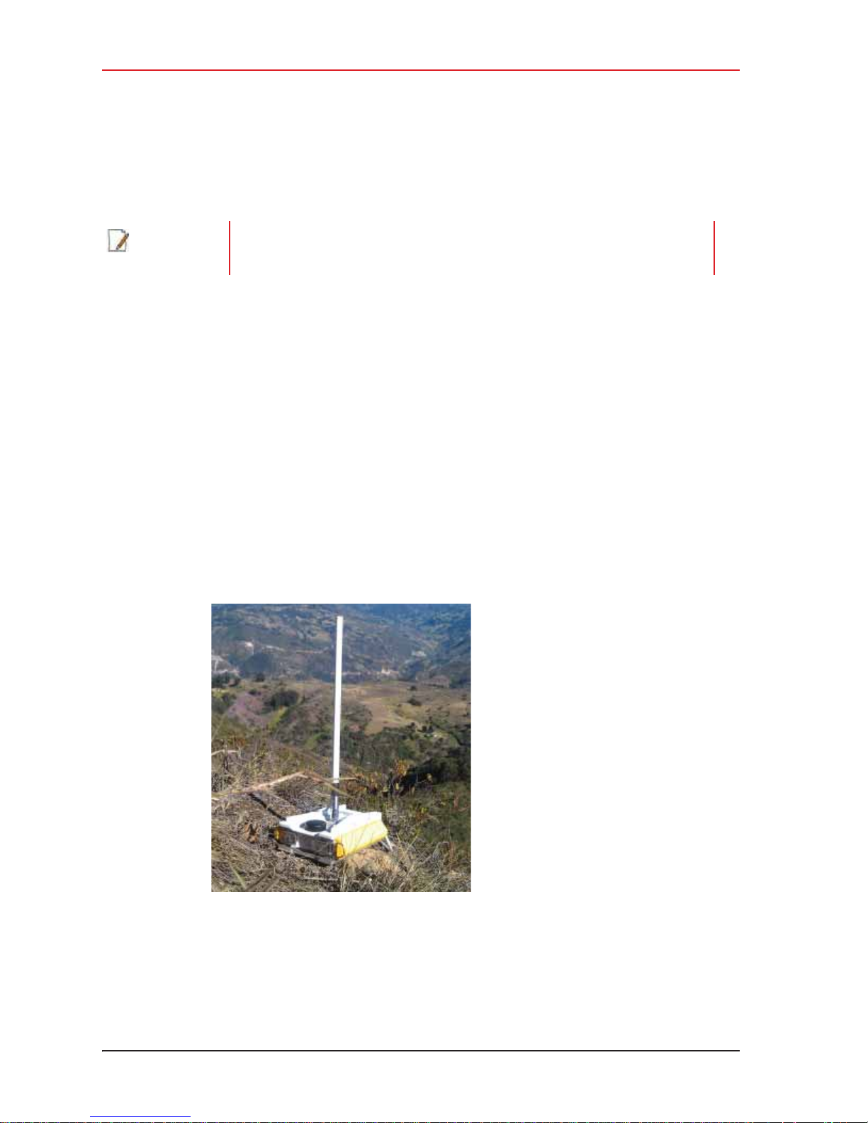
The WRU is shown in the following figure:
Figure 2–1 WRU
12 RT System 2 v2.3 Deployment Guide R01.i
© 2010-2014 Wireless Seismic, Inc. All rights reserved.
Page 13
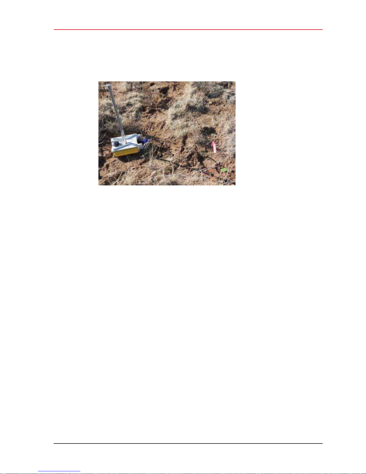
A WRU with a geophone attached is shown in the following figure
Figure 2–2 WRU with Geophone
2. Layout
Laying Out the Equipment
R01.i RT System 2 v2.3 Deployment Guide 13
© 2010-2014 Wireless Seismic, Inc. All rights reserved.
Page 14
2. Layout
Laying Out the Equipment
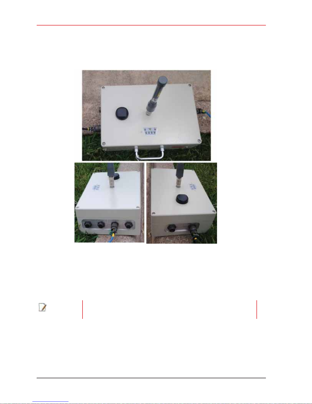
The LIU is shown in the following figure:
Figure 2–3 LIU
2.4.1 Prerequisites
Attach the batteries, antennas, anchor plates, and geophones to the ground equipment prior
to going into the field, or as each unit is placed. If you are assembling as you place the units,
ensure that you have sufficient quantities for each unit, plus a few spares.
NOTE
14 RT System 2 v2.3 Deployment Guide R01.i
Do not deploy (tip to power on) the WRUs until they are at the actual location
where they will be placed.
© 2010-2014 Wireless Seismic, Inc. All rights reserved.
Page 15
2. Layout
CAUTION
PRUDENCE
Laying Out the Equipment
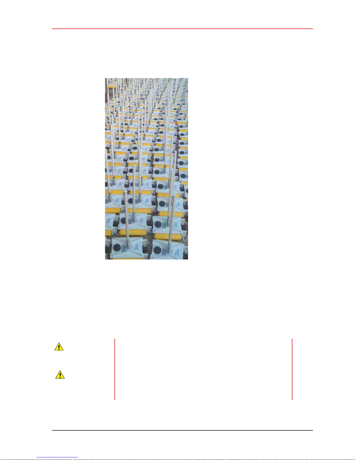
Figure 2–4 Assembling WRUs
The RT System 2 shall be used with only the supplied antennas (Table A–1 Antenna
Specifications, on page 145) attached to the WRU with an integrated type N male (threaded
or HPQN) connector.
i The RT System 2 antennas shall be installed and handled by professionals specifically
designated for this purpose.
i Changes or modifications not expressly approved by Wireless Seismic, Inc. can void the
users’s authority to operate the equipment.
In order to comply with radio frequency (RF) exposure requirements,
the RT System 2 units must be installed so that a minimum separation
distance of 20 cm is maintained between the antenna(s) and the body
of all persons at all times during normal operation.
Afin de se conformer aux normes de la en matière d'exposition aux
radiofréquences (RF), les unités RT System 2 doivent être installées de
manière à garder en permanence une distance minimale de 20 cm entre
la ou les antennes et le corps de toute personne en mode de
fonctionnement normal.
R01.i RT System 2 v2.3 Deployment Guide 15
© 2010-2014 Wireless Seismic, Inc. All rights reserved.
Page 16

2. Layout
VORSICHT
PRZESTROGA
CAUTION
PRUDENCE
VORSICHT
PRZESTROGA
Laying Out the Equipment
Um den Radiofrequenz-Strahlen-belastungsrichtlinien zu entsprechen,
müssen die RT-System 2 Einheiten so eingebaut werden, dass ein
Mindestabstand von 20 cm zwischen der/n Antenne/n und dem/n
Körper/n aller Personen zu jeglicher Zeit während der üblichen
Betriebszeiten gewährleistet ist.
Aby zachowaü zgodnoĞü z wymogami dotyczącymi ekspozycji na
promieniowanie o czĊstotliwoĞci radiowej (RF), urządzenia RT System 2
naleĪy instalowaü tak, aby podczas normalnej obsáugi pomiĊdzy ciaáem
wszystkich osób a antenami przez caáy czas byáo co najmniej 20 cm
odstĊpu.
2.4.2 Assembling the Ground Equipment
This section describes the process to assemble the ground equipment prior to deployment.
To assemble the ground equipment:
1 Gather the equipment:
Ɣ WRU
Ɣ Antenna
Ɣ Antenna Extender
Ɣ Geophone
Ɣ Batteries
Ɣ Anchor plates
2 Gather any special tools and equipment:
Ɣ Optional: Nylon grip pliers
Ɣ Optional: Loctite® 222
Ɣ Safety gear such as vests, hard hat, and gloves.
The metal ground equipment can become hot while exposed to the sun.
Wear gloves to handle hot equipment.
Les équipements terrestres en métal peuvent devenir chauds lorsqu’ils
sont exposés au soleil. Portez des gants lorsque vous manipulez un
équipement chaud.
Die Metallbodenausrüstung kann heiß werden, wenn sie der
Sonneneinstrahlung ausgesetzt wird. Tragen Sie Handschuhe, wenn Sie
mit erhitzter Ausrüstung umgehen.
Metalowe elementy urządzeĔ w terenie mogą nagrzaü siĊ w przypadku
wystawienia na sáoĔce. Nagrzane urządzenia naleĪy obsáugiwaü
w rĊkawicach.
3 Attach one or more batteries to the WRU.
Ɣ Press the battery into the connector.
Ɣ Flip the bail over the molded area on the end of the battery.
Ɣ Press the lever until the catch snaps to lock it in place.
16 RT System 2 v2.3 Deployment Guide R01.i
© 2010-2014 Wireless Seismic, Inc. All rights reserved.
Page 17
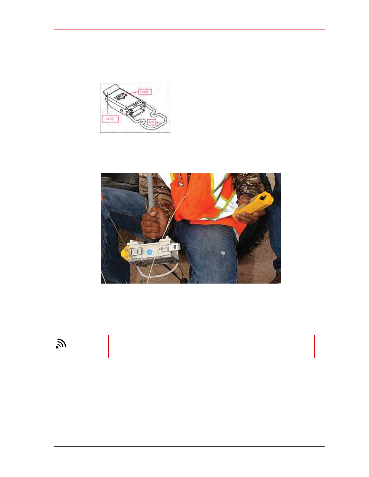
Figure 2–5 Battery Latch
2. Layout
Laying Out the Equipment
Figure 2–6 Installing the Battery
4 Optional: Attach the anchor plate. See “WRU Anchor Plate” on page 22 for instructions.
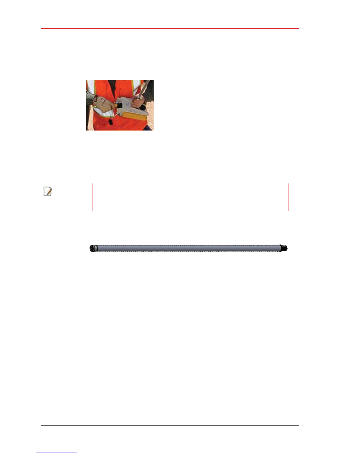
5 Attach the geophone to the WRU.
TIP
R01.i RT System 2 v2.3 Deployment Guide 17
To record three components of seismic data with the multiple-channel WRU,
connect three separate arrays of one-component geophones to the same WRU,
or connect a multiple-component geophone to the WRU
© 2010-2014 Wireless Seismic, Inc. All rights reserved.
Page 18
2. Layout
Laying Out the Equipment
NOTE
Figure 2–7 Installing the
Geophone
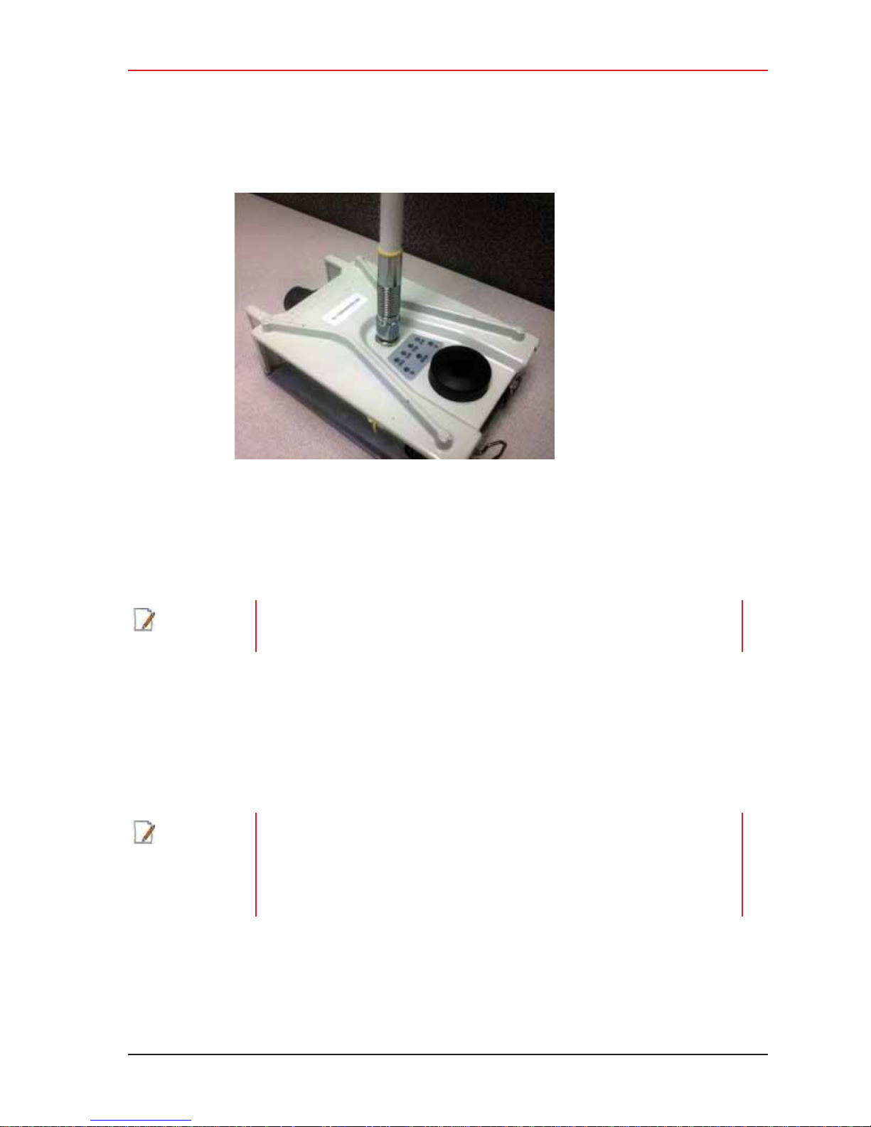
6 Attach the antenna with extender to the WRU. Ensure that the antenna connection is
clean, and the antenna is snug and does not wobble.
The antenna screws on to the WRU in a clockwise direction. It should twist on
easily; do not use force. To ensure that the threads are properly aligned, turn
the connector counter-clockwise until you hear a click indicating that the threads
are aligned, then turn clockwise to tighten.
Figure 2–8 Antenna Extender (65-0091)
18 RT System 2 v2.3 Deployment Guide R01.i
© 2010-2014 Wireless Seismic, Inc. All rights reserved.
Page 19
2. Layout
Laying Out the Equipment
Figure 2–9 Antenna with Spring Relief
2.4.3 Placing the WRU in the Field
This section describes the process to ready the ground equipment for interaction with the
central recording system (deployment).
NOTE
NOTE
Do not deploy (tip to power on) the WRUs until they are at the actual location
where they will be placed.
To deploy the WRU:
1 Prerequisites:
Ɣ The WRU is assembled with battery, geophone, and antenna
Ɣ Optional: The anchor plate is attached to the WRU
When using a WRU as a Repeater, the deployment instructions are the same,
except a geophone is not required. Repeaters are added to the line segment in
the Spread Manager. See the RT System 2 Operator Guide for more information.
If a geophone is not connected, you can skip the geophone test. See “D. LED
Indicators” on page 163 for more information on skipping the test and the
relevant LED status indicators.
2 Pick up the WRU and point the geophone connector end towards the ground as shown in
the following figure. After a few seconds, all of the LEDs illuminate:
R01.i RT System 2 v2.3 Deployment Guide 19
© 2010-2014 Wireless Seismic, Inc. All rights reserved.
Page 20

2. Layout
Laying Out the Equipment
Figure 2–10 Power on the Unit
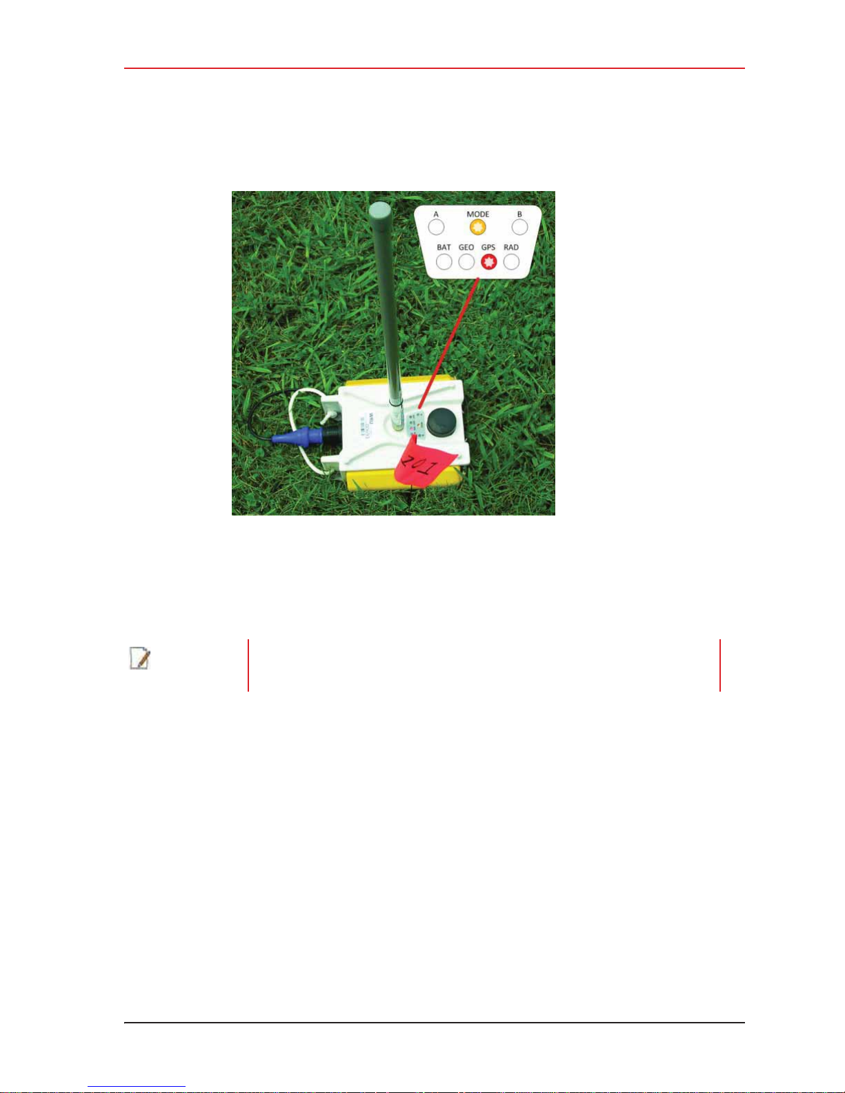
3 Place the unit flat on the ground as shown in the following figure:
20 RT System 2 v2.3 Deployment Guide R01.i
© 2010-2014 Wireless Seismic, Inc. All rights reserved.
Page 21
2. Layout
Laying Out the Equipment
NOTE
Figure 2–11 Place the Unit
4 The unit first turns on its GPS and acquires a new position. Then it will begin a series of
internal and external tests. The LEDs on the top of the unit indicate the current test and
whether the unit passes or fails each test.
The WRU will attempt to get a 3-meter GPS lock for up to 15 minutes. During
this time, the GPS LED flashes. The WRU will not form until the GPS lock is
achieved. If the GPS lock cannot be achieved, form by serial number.
5 Press or stomp the geophone into the ground. If you stomp the geophone while the
geophone test is running, the test will fail and the WRU will not deploy.
Verify that the WRU does not show a GEO self-test failure (see the following figure) after
placing the geophone. If the WRU does show a self-test failure, pick up the WRU, point
the geophone connector end towards the ground until all of the LEDs illuminate, and then
place the unit flat on the ground to re-run the self-test.
R01.i RT System 2 v2.3 Deployment Guide 21
© 2010-2014 Wireless Seismic, Inc. All rights reserved.
Page 22

2. Layout
WRU Anchor Plate
Figure 2–12 Geophone Self-Test
Failure
NOTE
See “D. LED Indicators” on page 163 for an explanation of the LED status and
error conditions.
If a WRU self test fails, the WRU will continue to the next test.
Skip a self-test by tipping the WRU geophone down and then returning it to the
upright position (flat on the ground).
6 Optional: If the WRU has an anchor plate attached, attach the WRU and anchor plate to
the ground with three large nails or stakes; two at the geophone end and one at the end
opposite of the geophone.
2.4.4 Placing the LIU in the Field
The LIU is part of the backhaul configuration. See “3. Backhaul” on page 26 for more
information.
2.5 WRU Anchor Plate
This WRU Anchor Plate (10-0028) is designed to reduce downtime due to tipped units and to
reduce losing units as a result of theft. The shape maintains the WRU stacking ability while
providing three solid anchor points. Constructed of light-weight and durable thermoplastic
polyurethane, it attaches to the bottom of the WRU with minimal effort while maintaining the
integrity of the WRU seal.
The anchor plate is compatible with the temperature range of the WRU which is -40°C to
+75°C (-40°F to +167°F).
22 RT System 2 v2.3 Deployment Guide R01.i
© 2010-2014 Wireless Seismic, Inc. All rights reserved.
Page 23
2. Layout
WRU Anchor Plate
Figure 2–13 Attaching the Anchor Plate to the WRU
To use the anchor plate:
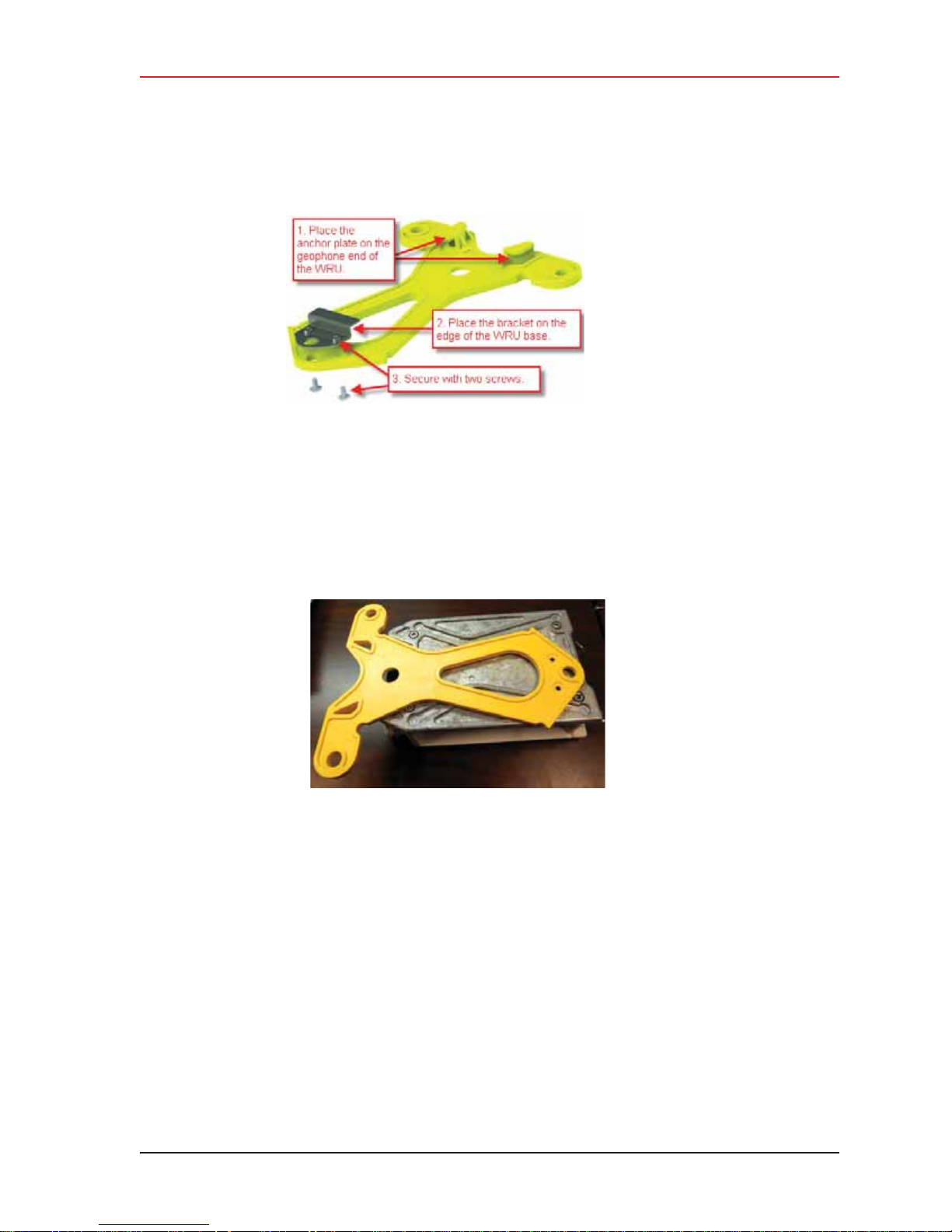
1 Attach the anchor plate to the WRU as shown in the following figures:
a Place the anchor plate on the geophone end of the WRU. The wide end of the anchor
plate slides on to the to the geophone end of the WRU.
Figure 2–14 Anchor Plate and WRU Alignment
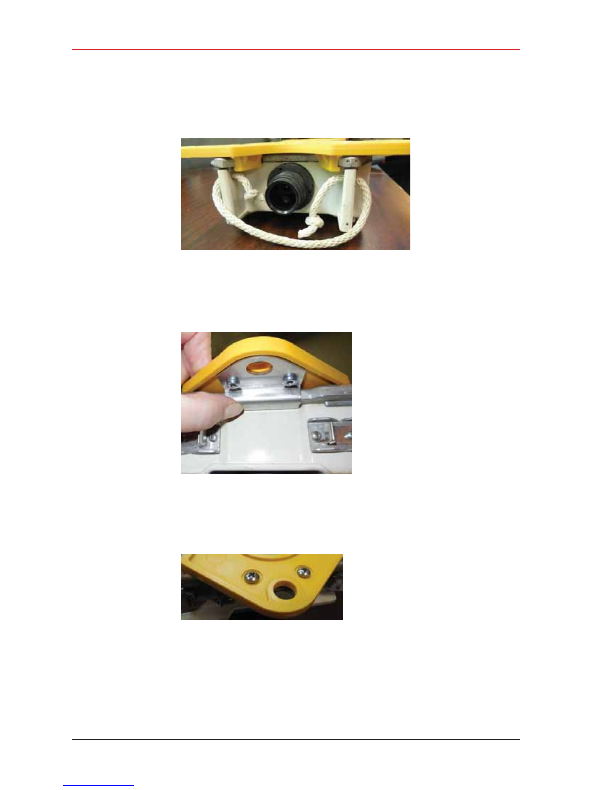
b Verify that the anchor plate is placed snugly against the WRU as shown in the
following figure:
R01.i RT System 2 v2.3 Deployment Guide 23
© 2010-2014 Wireless Seismic, Inc. All rights reserved.
Page 24
2. Layout
WRU Anchor Plate
Figure 2–15 Anchor Plate at WRU Geophone End
c Hold the bracket at the edge of the WRU base as shown in the following figure:
Figure 2–16 Anchor Plate Bracket
d Secure the bracket to the anchor plate with two screws.
Figure 2–17 Anchor Bracket Screws
24 RT System 2 v2.3 Deployment Guide R01.i
© 2010-2014 Wireless Seismic, Inc. All rights reserved.
Page 25
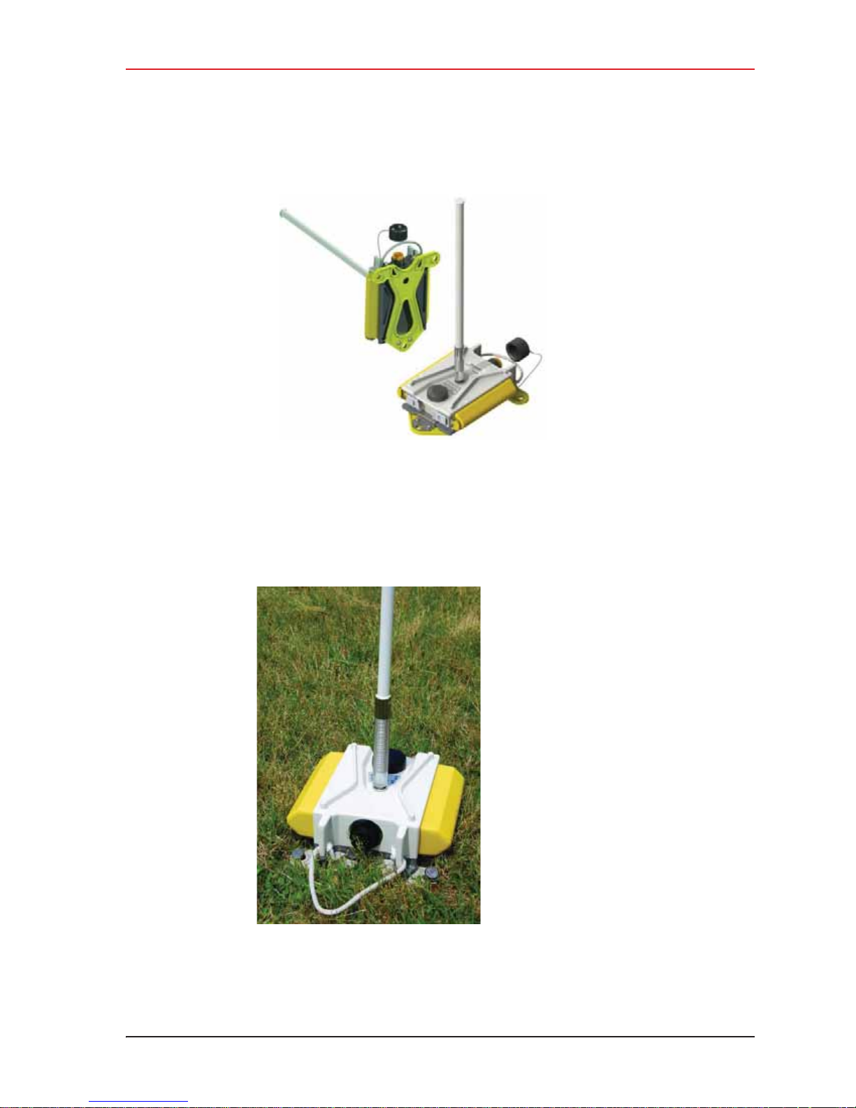
Figure 2–18 Anchor Plate Attached to WRU
2. Layout
WRU Anchor Plate
2 Attach the WRU and anchor plate to the ground with three large nails or stakes; two at
the geophone end and one at the end opposite of the geophone.
Figure 2–19 WRU Anchored with Anchor Plate
R01.i RT System 2 v2.3 Deployment Guide 25
© 2010-2014 Wireless Seismic, Inc. All rights reserved.
Page 26

3. Backhaul
3.1 Overview
In network communications, the backhaul is the part of the network that contains the
links and equipment between the core network and the sub networks. The following
table defines concepts associated with backhaul communications:
Table 3–1 Backhaul Communication Concepts
Term Definition Reference
3
Point-to-Point A method where each radio node in the
network captures and disseminates its own
data as well as serves as a relay for other
radio nodes in the network sending data
along a path, hopping from one node to the
next.
This is how the RT System 2 WRUs send
information to the LIU and how LIUs
communicate with each other in a point-topoint configuration.
Also called Bucket Brigade or String-ofPearls.
Point-to-Multipoint A method where each line station LIU
communicates directly with the recorder LIU.
The backhaul is composed of a number of
line station mast/radio/LIUs pointing to a
recording truck mast/radio/LIU. The following
list describes the most common
configurations:
• Point-to-Multipoint – A single
recording truck radio and multiple line
station radios
• Point-to-Multipoint (redundant) – A
single active recording truck radio, a
backup (redundant) recording truck
radio, and multiple line station radios
• Point-to-Multipoint (custom) – A
combination of recording truck radios
and line station radios
Also called Star Configuration.
• “Point-to-Point Single
Backhaul Data Direction” on
page 28
• “Poi nt-to-Point Dual Backhaul
Data Direction” on page 29
• “4. Point-to-Point Backhaul”
on page 65
• “Point-to-Multipoint Backhaul
Data Direction” on page 30
• “5. Point-to-Multipoint
Backhaul” on page 98
RT System 2 v2.3 26 Deployment Guide R01.i
© 2010-2014 Wireless Seismic, Inc. All rights reserved.
Page 27

Table 3–1 Backhaul Communication Concepts
Term Definition Reference
3. Backhaul
Overview
Power over Ethernet
(PoE)
In the RT System 2 system, the LIU communicates with the Central Software System (CSS)
computer in the central recording truck along a backhaul on the
5.8 GHz Industrial, Scientific, and Medical (ISM) radio band. Some smaller systems may not
require a backhaul.
A technology that passes electrical power
along an Ethernet cable. PoE is used where
DC power is not available and USB
unsuitable. Power can be supplied at the end
of a network span or somewhere in the
middle.
PoE switches supply power at the end of a
span. The RT System 2 Line Interface Unit
(LIU) acts as a switch with PoE.
PoE injectors supply power somewhere
between the PoE switch and the powered
device. They inject power and do not affect
the data. A discrete PoE injector is used
when configuring the backhaul radios.
• “Ubiquiti Rocket/Bullet Private
Network Connection” on page
107
• “Ubiquiti NanoStation Private
Network Connection” on page
72
R01.i RT System 2 v2.3 Deployment Guide 27
© 2010-2014 Wireless Seismic, Inc. All rights reserved.
Page 28
3. Backhaul
Overview
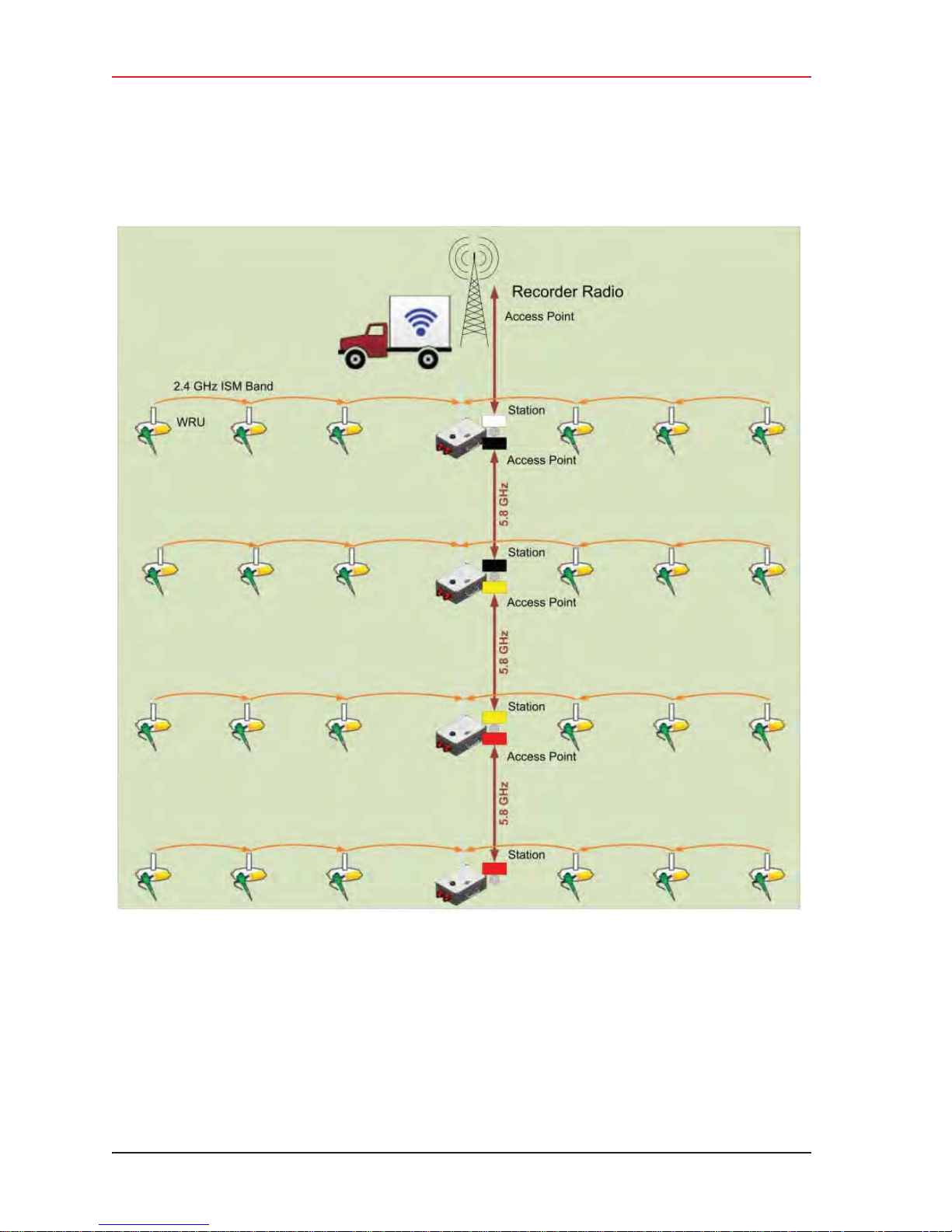
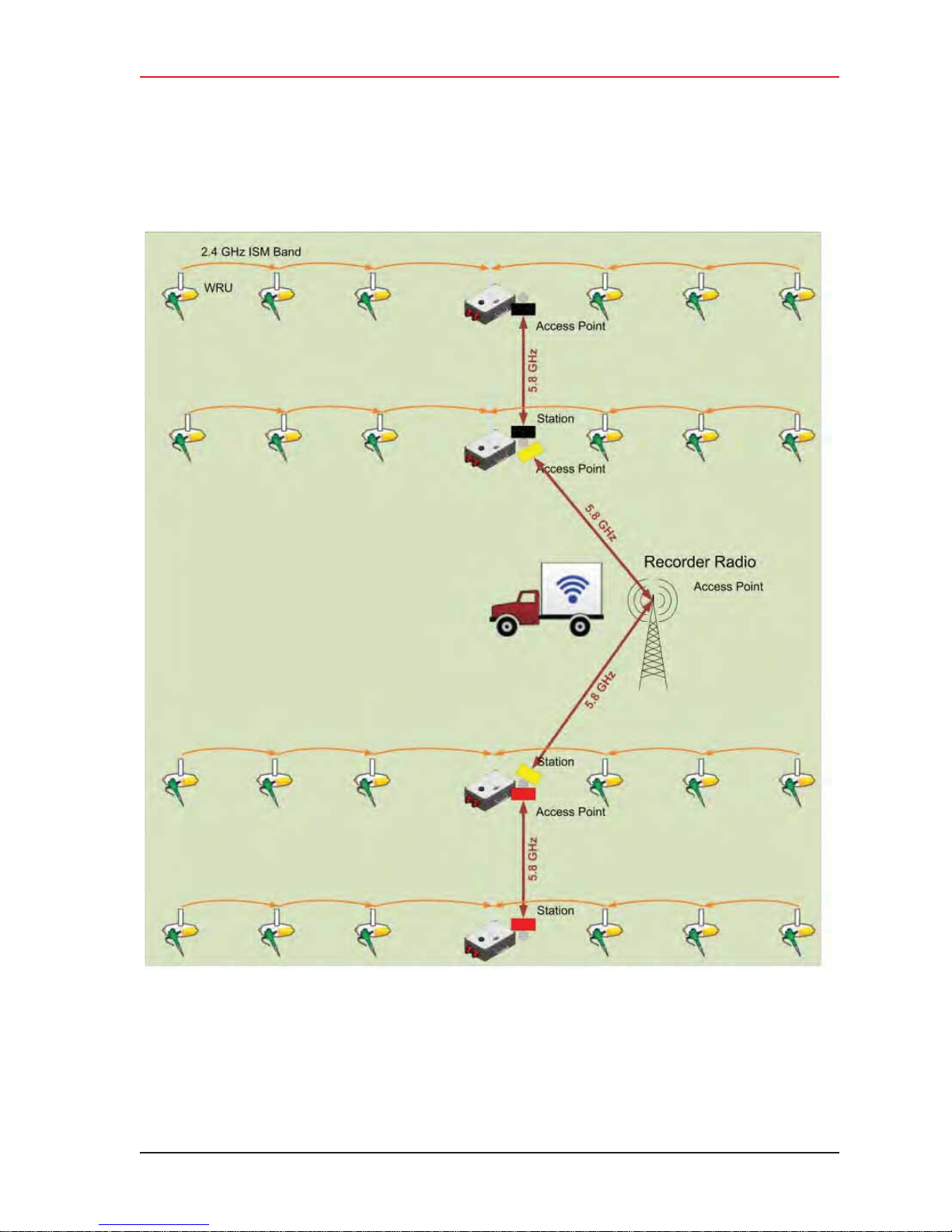
The following figure illustrates the components and data flow for a four-line, single-backhaul,
point-to-point line:
Figure 3–1 Point-to-Point Single Backhaul Data Direction
28 RT System 2 v2.3 Deployment Guide R01.i
© 2010-2014 Wireless Seismic, Inc. All rights reserved.
Page 29
3. Backhaul
Overview
The following figure illustrates the components and data flow for a four-line, dual-backhaul,
point-to-point line:
Figure 3–2 Point-to-Point Dual Backhaul Data Direction
R01.i RT System 2 v2.3 Deployment Guide 29
© 2010-2014 Wireless Seismic, Inc. All rights reserved.
Page 30
3. Backhaul
Overview
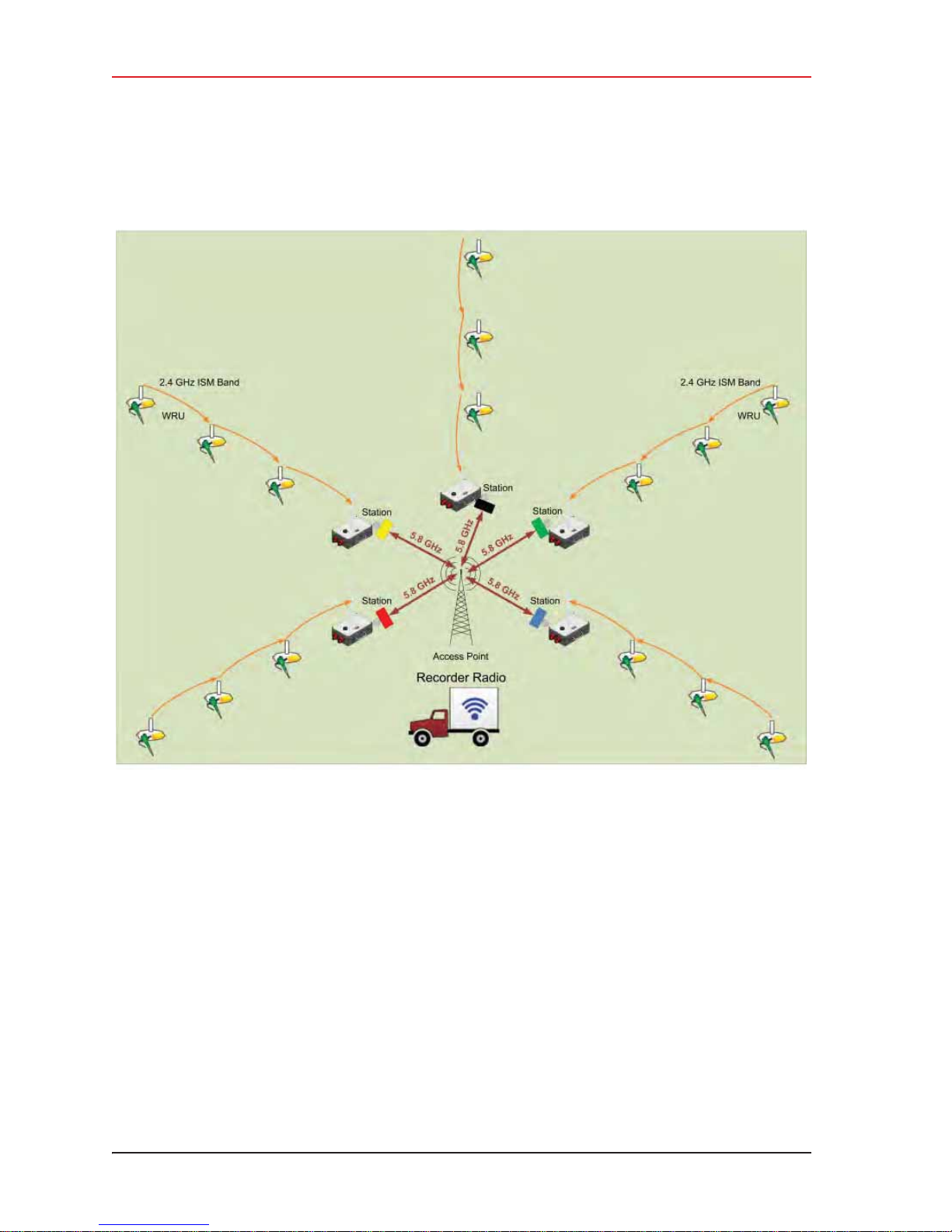
The following figure illustrates the components and data flow for a point-to-multipoint, star
configuration:
Figure 3–3 Point-to-Multipoint Backhaul Data Direction
30 RT System 2 v2.3 Deployment Guide R01.i
© 2010-2014 Wireless Seismic, Inc. All rights reserved.
Page 31

Backhaul Components
3.2 Backhaul Components
The backhaul components are either line station (remote) backhaul components or recorder
(central) backhaul components. Line station components are the components that are not
physically located next to the recording truck. Recorder components are physically located at
the recording truck.
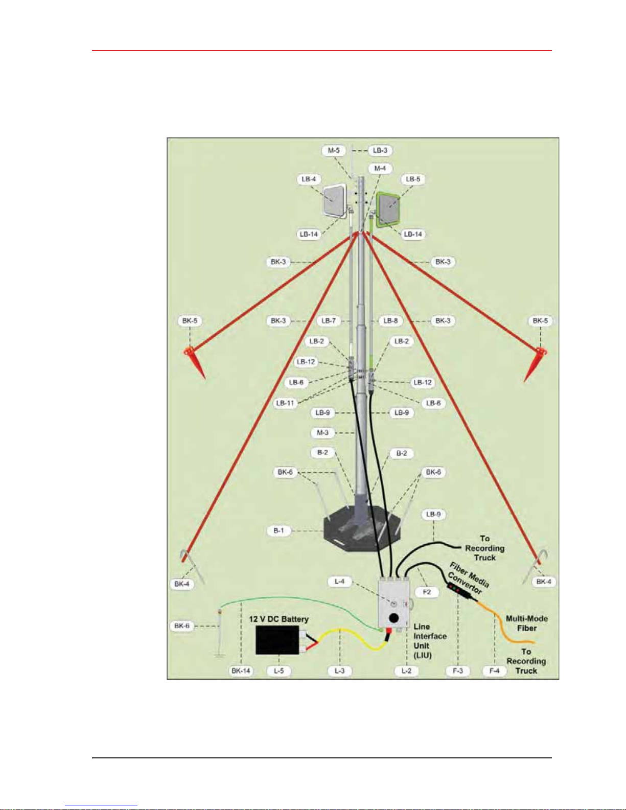
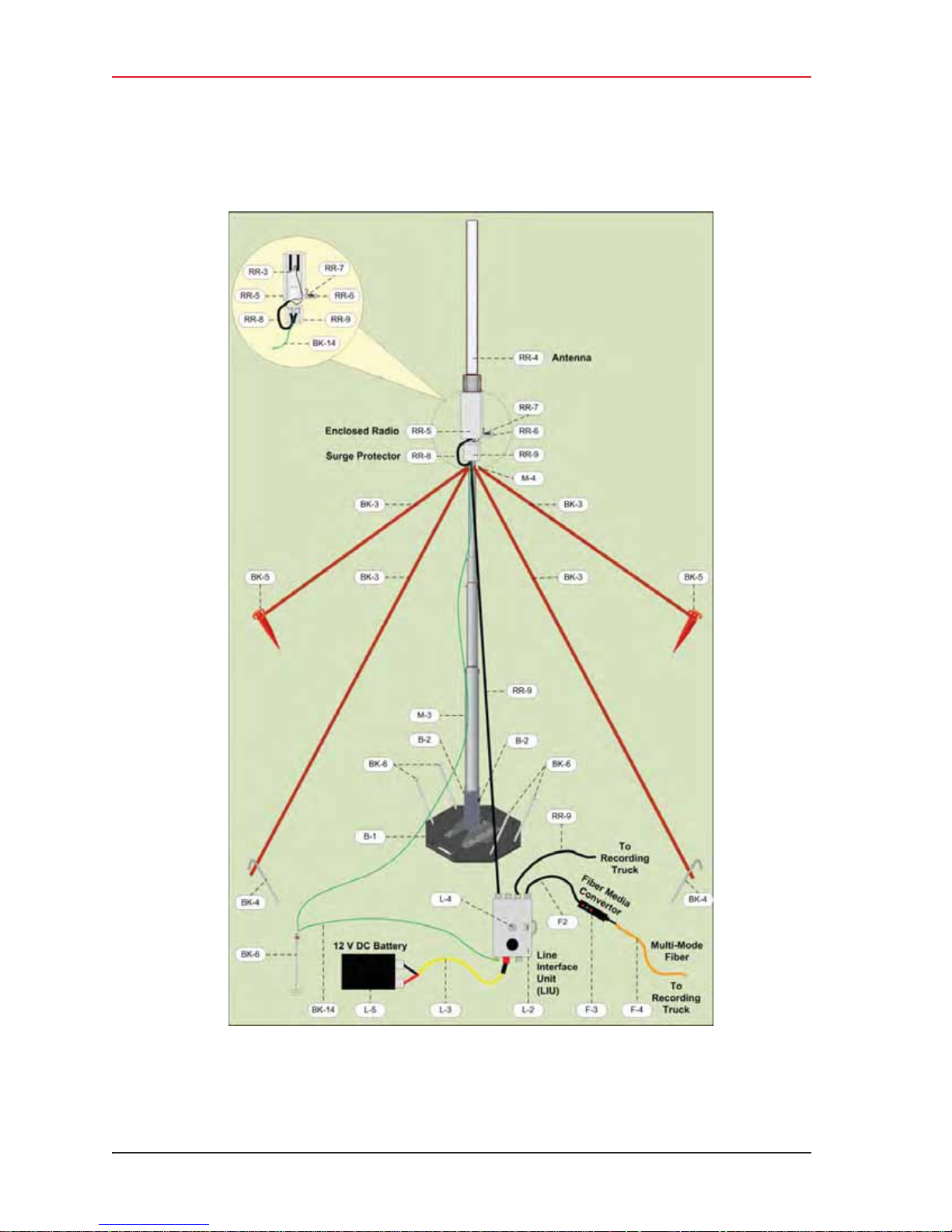
The following tables and figures illustrate the backhaul components.
Table 3–2 Backhaul Components, LIU, Mast, and Fiber
# EA Item Line Recorder Reference
L-1 1 LIU Kit (15-0041) Y Y —
L-2 1 • LIU (10-0016) Y Y “LIU” on page 38
3. Backhaul
L-3 1 • Cable, LIU to Battery, yellow (60-
L-4 — • An antenna is required to
L-5 — • A 12 V DC Battery is required, but
M-1 1 Mast Kit (15-0046) Y Y —
M-2 1 • Mast (15-0051) Y Y “Mast and Base” on page 49
M-3 1
0034)
communicate with the WRUs.
not included.
– 20 ft Telescoping Mast (70-
YY“Cable Assemblies” on page
45
YY“LIU and WRU Antennas” on
page 39
YY“LIU and WRU Antennas” on
page 39
YY—
0130)
M-4 1
M-5 1
– Mast Guy Ring (70-0133)
– Bracket, Omni Antenna
YY—
YY—
(70-0136)
B-1 1 • Base (55-0050) Y Y “Mast and Base” on page 49
B-2 2
– Knob, 10-32 x 1/2 inch
YY—
Threaded Stud (70-0137)
BK-1 1 • Backpack Kit (15-0014) Y Y “Setting up the Backhaul” on
BK-2 1
– Backpack, Red/Grey (70-
YY—
page 50
0059)
BK-3 4
– Antenna Mast Guy Line, 4
YY—
mm, 15.25 m, Orange (70-
0057)
BK-4 4
– Tent Stake, Steel, 12 in
(70-0061) (hard ground
stakes)
BK-5 4
– Tent Stake, Plastic, 16 in,
Orange (70-0060) (soft
ground stakes)
BK-6 5
BK-7 4
– Nail, 12 in (70-0062)
– Guy Line Holder (70-0063)
R01.i RT System 2 v2.3 Deployment Guide 31
YY—
YY—
YY—
YY—
© 2010-2014 Wireless Seismic, Inc. All rights reserved.
Page 32

3. Backhaul
Backhaul Components
Table 3–2 Backhaul Components, LIU, Mast, and Fiber (cont.)
# EA Item Line Recorder Reference
BK-8 1
BK-9 1
BK-10 2
– Hammer, 2.5 lb (70-0064)
– Pry Bar, 15 in (70-0065)
– Flagging Roll, Orange (70-
0066)
BK-11 1
– Compass Sighting (70-
0067)
BK-12 5
– Hose Clamp, 2 in (70-
0142)
BK-13 2
– Hose Clamp, 0.5 in (70-
0084)
BK-14 15
ft
F-1 1 • Fiber Backhaul Kit, 250 m (15-
F-2 1
F-3 1
– Wire, 18AWG Green (65-
0077)
0037)
– OR –
• Fiber Backhaul Kit, 500 m (15-
0038)
– Media Converter (60-0017)
– Cable, Backhaul Jumper
(60-0033)
F-4 1
–Cable, Fiber Optic,
Armored, 250 m (60-0026)
– OR –
–Cable, Fiber Optic,
Armored, 500 m (60-0023)
YY—
YY—
YY—
YY“F. Using a Compass” on
page 184
YY—
YY—
YY—
Y Y —
YY“Cable Assemblies” on page
45
YY“Cable Assemblies” on page
45
YY“Cable Assemblies” on page
45
Table 3–3 Backhaul Components, Radios
# EA Item Line Recorder Reference
LB-1
LB-2 2 • 5 GHz Radio (US) (56-0019 US)
LB-3 1 • 5.8 GHz 6 dBi Omni Antenna (65-
Ubiquiti Bullet Radio
1
Line Radio Kit (US) (15-0044)
– OR –
1
Line Radio Kit (Intl) (15-0053)
– OR –
• 5 GHz Radio (Intl) (56-0024)
0179)
32 RT System 2 v2.3 Deployment Guide R01.i
© 2010-2014 Wireless Seismic, Inc. All rights reserved.
Y — —
Y—“Bullet Line Station Radios”
on page 157
Y—“Bullet Line Station Antenna”
on page 149
Page 33

3. Backhaul
Backhaul Components
Table 3–3 Backhaul Components, Radios (cont.)
# EA Item Line Recorder Reference
LB-4 1 • 5.8 GHz 19 dBi Panel Antenna, W
LB-5 1 • 5.8 GHz 19 dBi Panel Antenna, G
LB-6 1 • Bracket, Line Radio (55-0047) Y — —
LB-7 2 • Cable, Armored Ethernet, 10 ft,
LB-8 1 • Cable, Armored Ethernet, 15 ft,
LB-9 2 • Cable, Shielded Ethernet, 15 ft,
LB-10 1 • Carrying Case (70-0138) Y — —
LB-11 1 • Hose Clamp, 4 in (70-0140) Y — —
LB-12 1 • Hose Clamp, 2 in (70-0142) Y — —
LB-13 1 • Nut Driver, 5/16 in (70-0147) Y — —
LB-14 2 • Elbow connector (comes with 15-
RR-1
1
1
Polarization (56-0020)
Polarization (56-0021)
White (60-0053)
Green (60-0055)
Black (60-0054)
0044 and 15-0053)
Ubiquiti Rocket Radio
Recorder Radio Kit (US) (15-0045)
– OR –
Recorder Radio Kit (Intl) (15-0055)
Y—“Bullet Line Station Antenna”
Y—“Bullet Line Station Antenna”
Y—“Cable Assemblies” on page
Y—“Cable Assemblies” on page
Y—“Cable Assemblies” on page
Y——
— Y —
on page 149
on page 149
45
45
45
RR-2 1
RR-3 1
RR-4 1
RR-5 1
RR-6 1
RR-7
• Recorder Radio and Antenna (US)
(15-0052)
– OR –
• Recorder Radio and Antenna (Intl)
1
(15-0054)
– 5 GHz Radio (US) (75-
0031 US)
– OR –
1
– 5 GHz Radio (Intl) (75-
0038)
– 5 GHz 13 dBI Dual Polarity
Omni Antenna (65-0178)
– Shield, Recorder Radio
Omni (70-0129)
– Bracket GPS Antenna
Holder (70-0148)
– GPS Antenna (comes with
15-0045 and 15-0055)
—Y—
—Y“Rocket Recorder Radios” on
page 159
—Y“Rocket Recorder Antenna”
on page 152
—Y“Cable Assemblies” on page
45
—Y—
—Y—
R01.i RT System 2 v2.3 Deployment Guide 33
© 2010-2014 Wireless Seismic, Inc. All rights reserved.
Page 34

3. Backhaul
Backhaul Components
Table 3–3 Backhaul Components, Radios (cont.)
# EA Item Line Recorder Reference
RR-8 1
– Cable, Shielded Ethernet, 3
ft, Black (65-0104)
—1
RR-9 1 • Surge Protector (75-0021) — Y “Surge Protector Box” on
RR-10 1 • Cable, Shielded Ethernet, 120 ft,
RR-11 60 ft• Wire, 18AWG Green (65-0077) — Y —
RR-12 1 • Case, Recorder Radio Kit (70-
RR-13 1 • Nut Driver, 5/16 in (70-0147) — Y —
RN-1
2
2
RN-2 2
– PoE Injector (75-0023)
Black (60-0038)
0139)
Ubiquiti NanoStation Radio Kit
• Recorder Radio Kit (US) (15-0068)
– OR –
• Recorder Radio Kit (Intl) (15-0067)
– 5 GHz Radio Assembly
—Y“Cable Assemblies” on page
45
——•“Ubiquiti Rocket/Bullet
Private Network
Connection” on page 107
• “Ubiquiti NanoStation
Private Network
Connection” on page 72
page 44
—Y“Cable Assemblies” on page
45
—Y—
— Y —
—Y—
(US) (56-0035 US)
– OR –
– 5 GHz Radio Assembly
(Intl) (56-0032)
RN-3 2
– Cable, Shielded Ethernet,
—Y—
120 ft, Black with Red
shrink tube (60-0036)
RN-4 3
– Strain Relief, Wedge Clamp
—Y—
.160/.330 DIA. (70-0171)
RN-5 1
– Case, NanoStation Line
—Y—
Radio (70-0176)
RN-6 1
– Nut driver, 7/16 in, Brown
—Y—
(70-0178)
RN-7 1
– Wrench, Double Open-end,
—Y—
7/16 in - 1/2 in (70-0179)
34 RT System 2 v2.3 Deployment Guide R01.i
© 2010-2014 Wireless Seismic, Inc. All rights reserved.
Page 35
3. Backhaul
Backhaul Components
R01.i RT System 2 v2.3 Deployment Guide 35
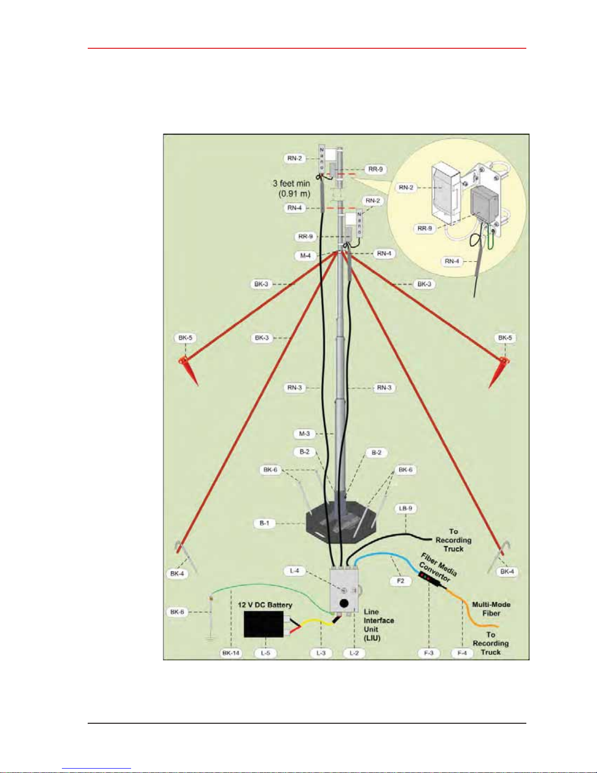
Figure 3–4 Line Station Backhaul Components
© 2010-2014 Wireless Seismic, Inc. All rights reserved.
Page 36
3. Backhaul
Backhaul Components
36 RT System 2 v2.3 Deployment Guide R01.i
© 2010-2014 Wireless Seismic, Inc. All rights reserved.
Figure 3–5 Recorder Backhaul Components
Page 37
3. Backhaul
Backhaul Components
R01.i RT System 2 v2.3 Deployment Guide 37
Figure 3–6 Recorder/Line NanoStation Backhaul Components
© 2010-2014 Wireless Seismic, Inc. All rights reserved.
Page 38
3. Backhaul
Backhaul Components
3.2.1 LIU
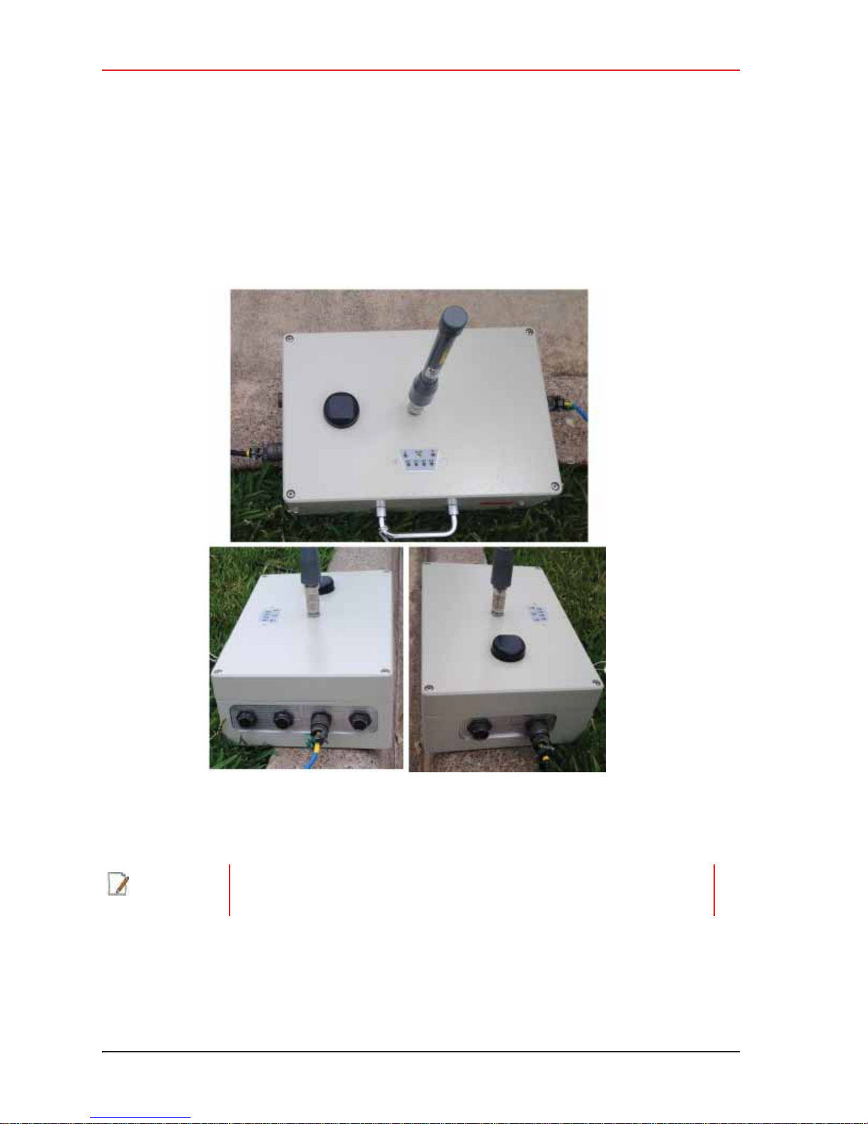
The data transmitted by the WRUs is collected by the Line Interface Unit (LIU). The LIU acts
as the interface between the network of WRUs and the backhaul equipment. The LIU has an
Ethernet port that can be connected directly to a computer, or more commonly, to an
armored fiber optic cable or a backhaul radio. Backhaul radios operate in the 5.8 GHz band.
A second array of WRUs can be deployed on the other side of the LIU, symmetrically or
asymmetrically around the LIU. The LIU is shown in the following figure:
Before the Central Software System can communicate with the LIU, you must set up the
backhaul.
NOTE
38 RT System 2 v2.3 Deployment Guide R01.i
See “D. LED Indicators” on page 163 for an explanation of the LED status and
error conditions.
© 2010-2014 Wireless Seismic, Inc. All rights reserved.
Figure 3–7 Line Interface Unit (LIU)
Page 39

3.2.2 LIU Battery
Power is supplied to the LIU components by way of a 12 V DC battery. The external battery is
not supplied as part of the backhaul system.
3. Backhaul
Backhaul Components
TIP
The backhaul power requirements vary depending on the hardware in use and
period of use. For example, you may be using one or two radios. Supply enough
power to ensure there is enough power for the entire duration of the time you
are using the backhaul.
See the Troubleshooting Guide, Best Practices chapter, LIU Batteries section for instructions
on how to hot-swap the LIU battery.
3.2.3 LIU and WRU Antennas
The following table lists the supported antennas for the LIUs and the WRUs (all models). The
remote and central backhauls use the same antennas:
Table 3–4 Antenna Specifications, WRU/LIU
Model
WSI 65-0204/65-0264
(antenna-standard)
WSI 65-0091
(extender-standard)
There is an auto-power-leveling feature built into the firmware. It works in conjunction with
the RSSI parameters to keep the power at a defined level. If the Unit Thresholds
Command (or Data) RSSI parameter is set to any number greater than zero, powerleveling is enabled.
Frequency
(MHz)
2400 5.5 dBi (50 ohm) 25° 0.4 lbs
2400 0 dBi N/A 0.6 lbs
Maximum Gain
Vertical
Beam Width
Weight
0.2 kg
0.3 kg
Dimension
(Length x
Diameter)
32 x 0.6 in
810.5 x 15 mm
30 x 0.7 in
762 x 18.5 mm
ĺ
3.2.4 Line Radios
There are two line radio options provided as follows:
i Ubiquiti Bullet – Currently supported for point-to-point (string-of-pearls) backhauls:
Ɣ 5 GHz Radio (US) (56-0019 US)
Ɣ 5 GHz Radio (Intl) (56-0024)
i Ubiquiti NanoStation M5 – Currently supported for point-to-multi-point (star)
backhauls:
Ɣ 5 GHz Radio Assembly (US) (56-0035 US)
Ɣ 5 GHz Radio Assembly (Intl) (56-0032)
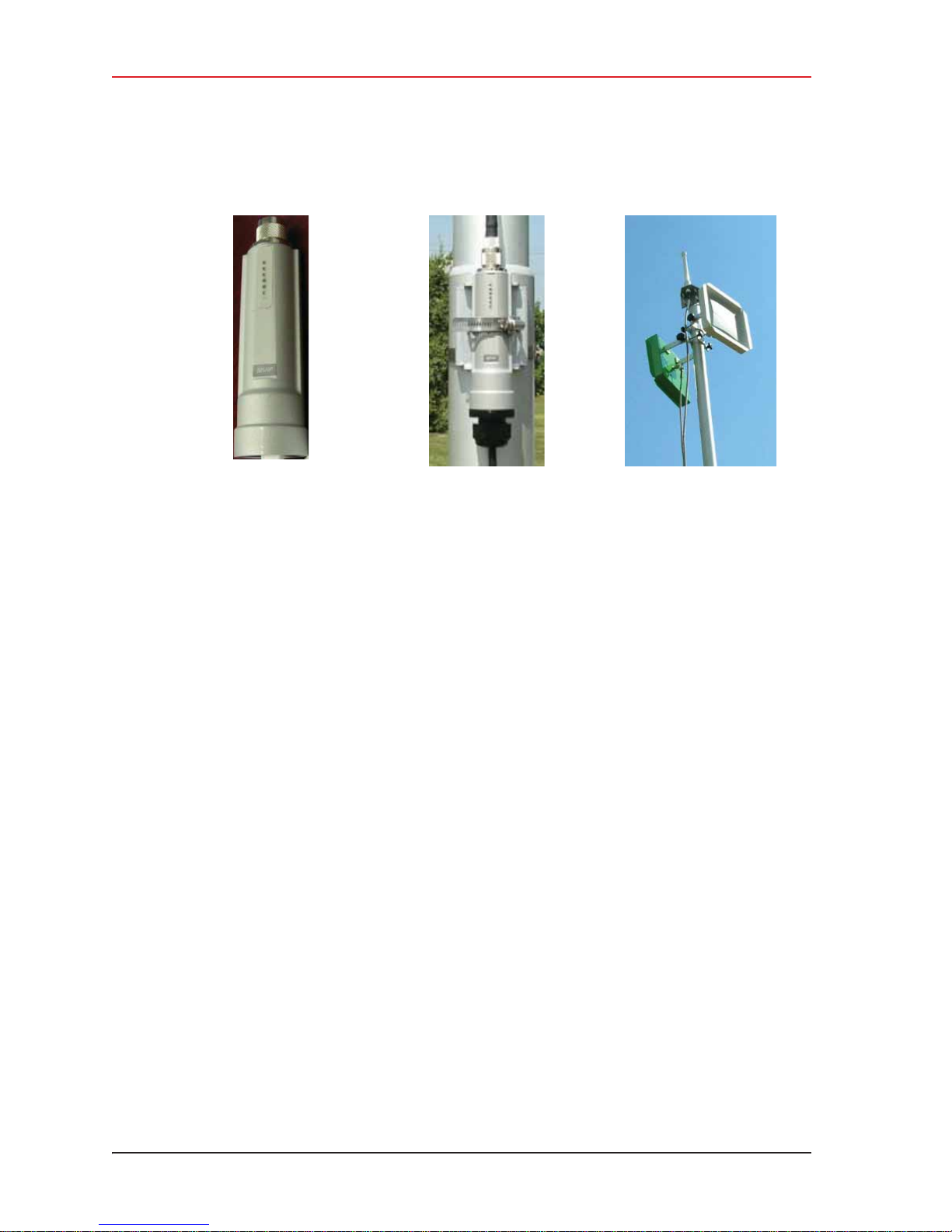
The Ubiquiti Bullet line radio is normally used with a directional antenna; however an
omnidirectional antenna is also included. The antennas are attached at the top of the mast
and the radio is attached to the mast at eye level as shown in the following figure.
R01.i RT System 2 v2.3 Deployment Guide 39
© 2010-2014 Wireless Seismic, Inc. All rights reserved.
Page 40
3. Backhaul
Backhaul Components
Figure 3–8 Line Radio and Antennas, Bullet
40 RT System 2 v2.3 Deployment Guide R01.i
© 2010-2014 Wireless Seismic, Inc. All rights reserved.
Page 41
3. Backhaul
Backhaul Components
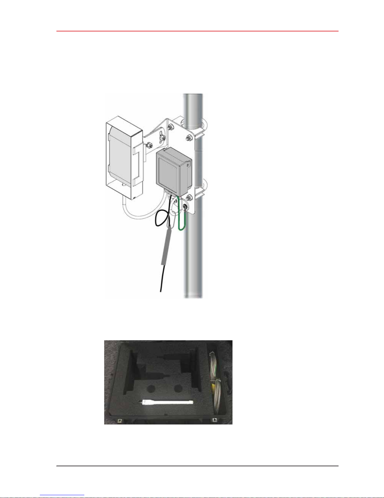
The Ubiquiti NanoStation M5 radio has an integrat ed (inter nal) antenna. Th e r adio is attached
at the top of the mast with a surge protector as shown in the following figure:
Figure 3–9 Line Radio, NanoStation
The line radios and antennas can be stored in their protective case when not in use:
Figure 3–10 Bullet Radio Case (70-0138)
R01.i RT System 2 v2.3 Deployment Guide 41
© 2010-2014 Wireless Seismic, Inc. All rights reserved.
Page 42
3. Backhaul
Backhaul Components
See “C. Radio Specifications” on page 149 for FCC information and other technical
specifications.
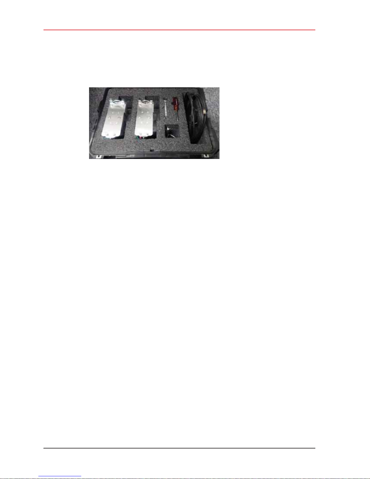
Figure 3–11 NanoStation Radio Case (70-0176)
3.2.5 Recorder Radio
There are two recorder radio options provided as follows:
i Ubiquiti Rocket – Currently supported for point-to-point (string-of-pearls) backhauls:
Ɣ Recorder Radio and Antenna (US) (15-0052)
Ɣ Recorder Radio and Antenna (Intl) (15-0054)
i Ubiquiti NanoStation M5 – Currently supported for point-to-multi-point (star)
backhauls
Ɣ 5 GHz Radio Assembly (US) (56-0035 US)
Ɣ 5 GHz Radio Assembly (Intl) (56-0032)
42 RT System 2 v2.3 Deployment Guide R01.i
© 2010-2014 Wireless Seismic, Inc. All rights reserved.
Page 43
3. Backhaul
Backhaul Components
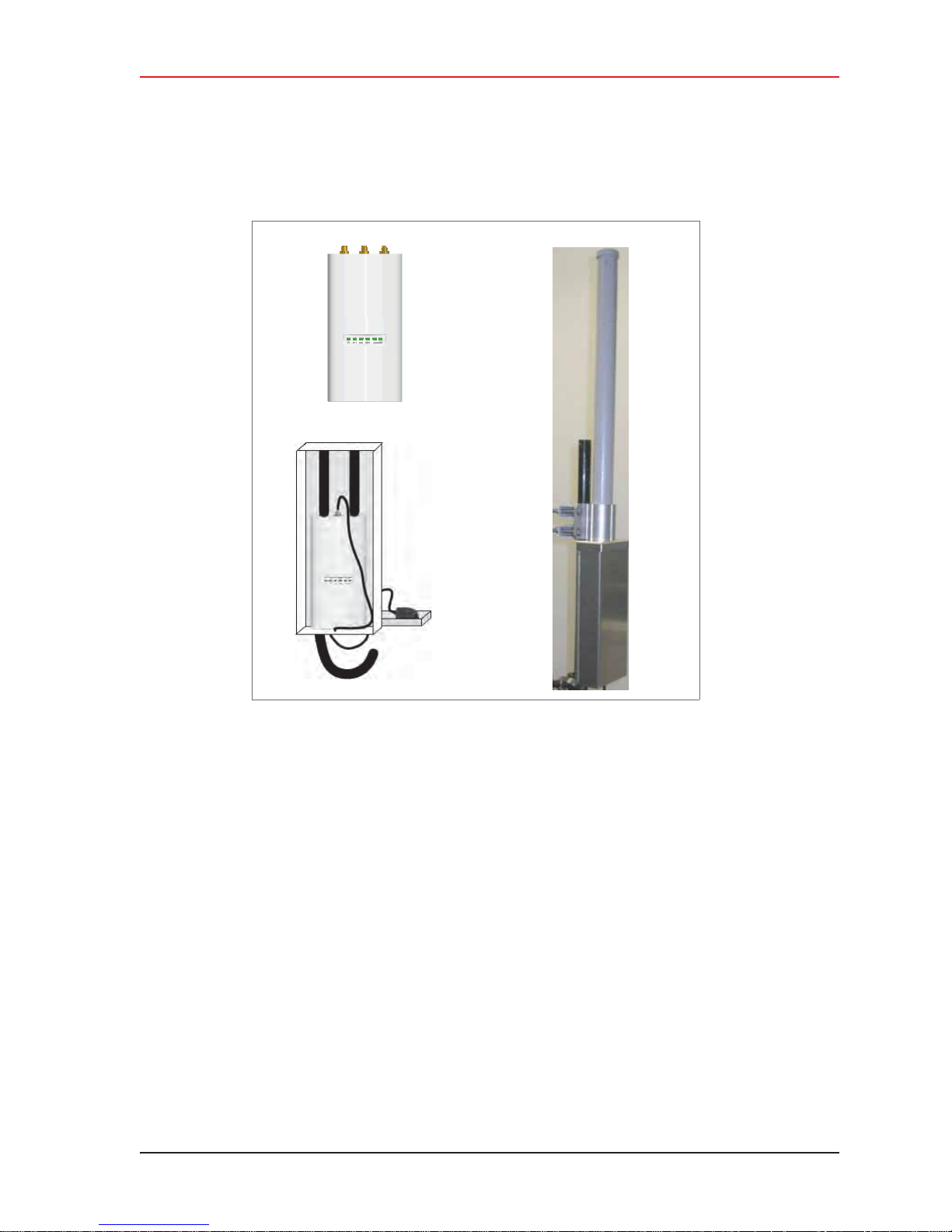
The Ubiquiti Rocket recorder radio is used with an omnidirectional antenna. It is attached to
the top of the mast and is shown in the following figure. The Rocket radio is completely
enclosed in a protective metal case when installed.
Figure 3–12 Recorder Radio
The Ubiquiti NanoStation M5 radio has an integrat ed (inter nal) antenna. Th e r adio is attached
at the top of the mast with a surge protector as shown in “Line Radio, NanoStation” on page
41.
See “C. Radio Specifications” on page 149 for FCC information and other technical
specifications.
R01.i RT System 2 v2.3 Deployment Guide 43
© 2010-2014 Wireless Seismic, Inc. All rights reserved.
Page 44
3. Backhaul
Backhaul Components
3.2.6 Radio Antennas
The following table lists the supported antennas for the radios:
Table 3–5 Antenna Specifications, Radios
Model
WSI 65-0178
2x2 Dual Polarity
MIMO Omni
WSI 65-0179
Omni
WSI 65-0177
Antenna Panel
Frequency
(MHz)
5450 - 5850 13 dBi 6.2x3.8x32.8 in
5275 - 5850 6 dBi 10.6 in
5150 - 5825 19 dBi 7.5 x 7.5 x 0.8 in
3.2.7 Surge Protector Box
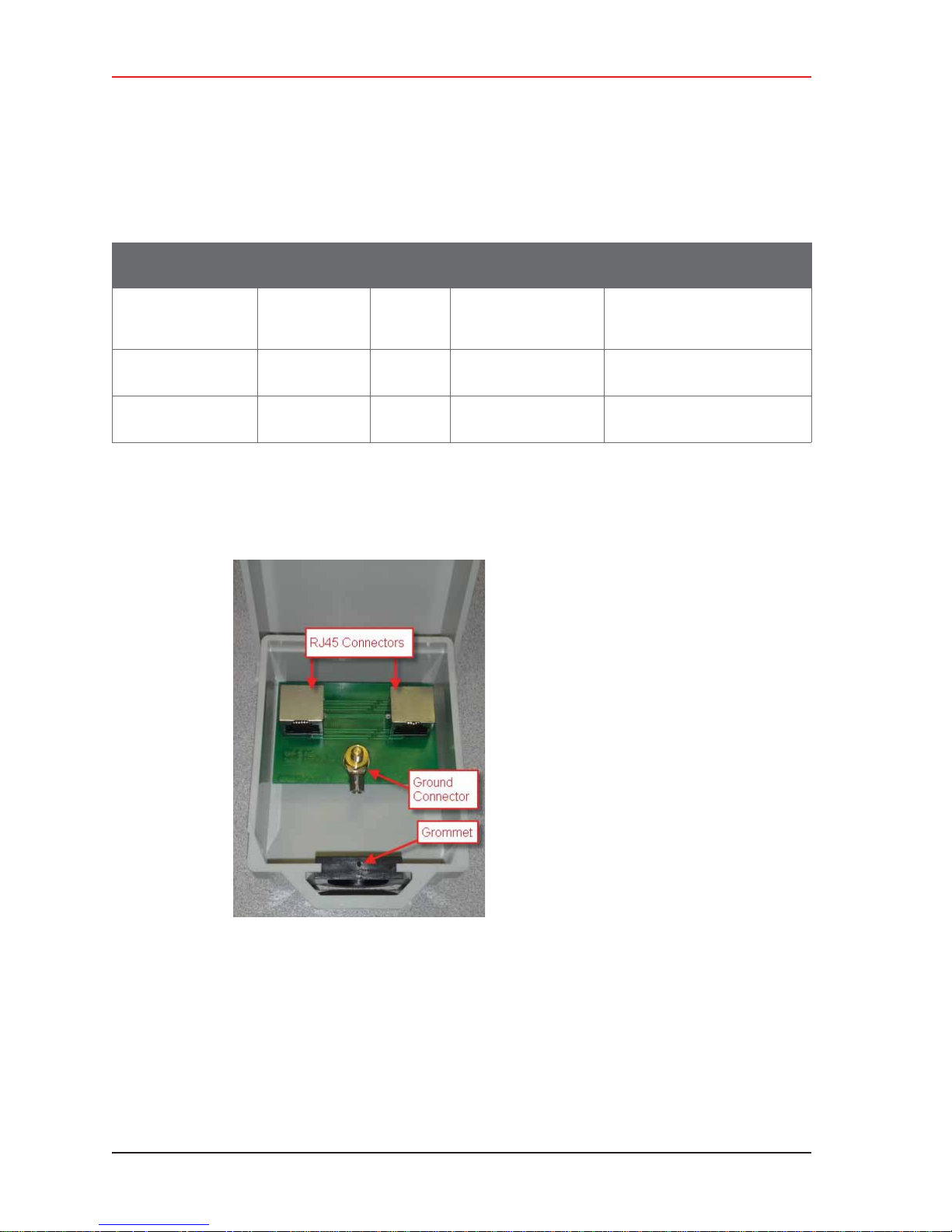
The following figure illustrates the inside of the Surge Protector Use a surge protector on
each mast between the Rocket radio or the NanoStation radio and the LIU.
Gain
Dimension (Length
x Diameter)
158x98x834 mm
269 mm
190 x 190 x 20 mm
See
“Rocket Recorder Antenna” on
page 152
“Bullet Line Station Antenna”
on page 149
“Bullet Line Station Antenna”
on page 149
Figure 3–13 Surge Protector
Connections
44 RT System 2 v2.3 Deployment Guide R01.i
© 2010-2014 Wireless Seismic, Inc. All rights reserved.
Page 45
3.2.8 Cable Assemblies
The following cables are used in the backhaul:
i Cable, LIU to Battery (60-0034)
i Cable, LIU to NanoStation Radio (60-0036)
i Cable, Ethernet, 120 ft Shielded, Black with Red shrink tube (60-0036)
i Cable, LIU-to-PC (60-0039)
i Cable, Ethernet, 3 ft Shielded (65-0104)
i Cable, Armored Ethernet, 10 ft (60-0053)
i Cable, Shielded Ethernet, 15 ft (60-0054)
i Cable, Armored Ethernet, 15 ft (60-0055)
i Cable, Shielded Ethernet, 120 ft (60-0038)
i Cable, RF Extender, 10 ft (65-0103)
i Cable, RF Extender, 25 ft (65-0110)
i Fiber Backhaul Kit, 250 m (15-0037)
Ɣ Media Converter (60-0017)
Ɣ Cable, Backhaul Jumper (60-0033)
Ɣ Cable, Fiber Optic, Armored, 250 m (60-0026)
i Fiber Backhaul Kit, 500 m (15-0038)
Ɣ Media Converter (60-0017)
Ɣ Cable, Backhaul Jumper (60-0033)
Ɣ Cable, Fiber Optic, Armored, 500 m (60-0023)
3. Backhaul
Backhaul Components
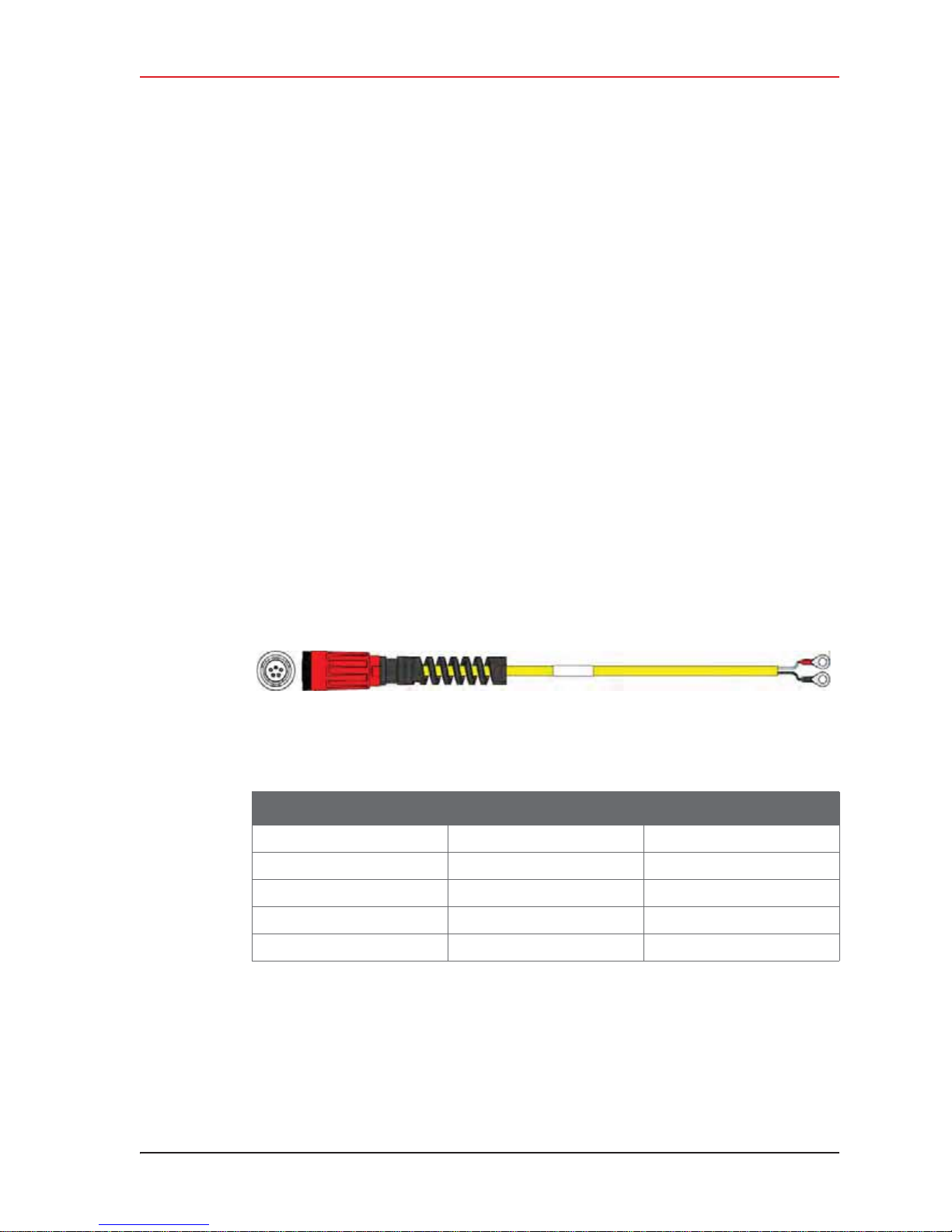
Figure 3–14 Cable, LIU to Battery (60-0034)
Table 3–6 Cable Pinout, LIU to Battery (60-0034)
5-Pin Connector 2-Terminal End Signal Name
ANC—
BWHT+V
CBLK5-V
DNC—
ENC—
R01.i RT System 2 v2.3 Deployment Guide 45
© 2010-2014 Wireless Seismic, Inc. All rights reserved.
Page 46
3. Backhaul
CAUTION
PRUDENCE
VORSICHT
PRZESTROGA
Backhaul Components
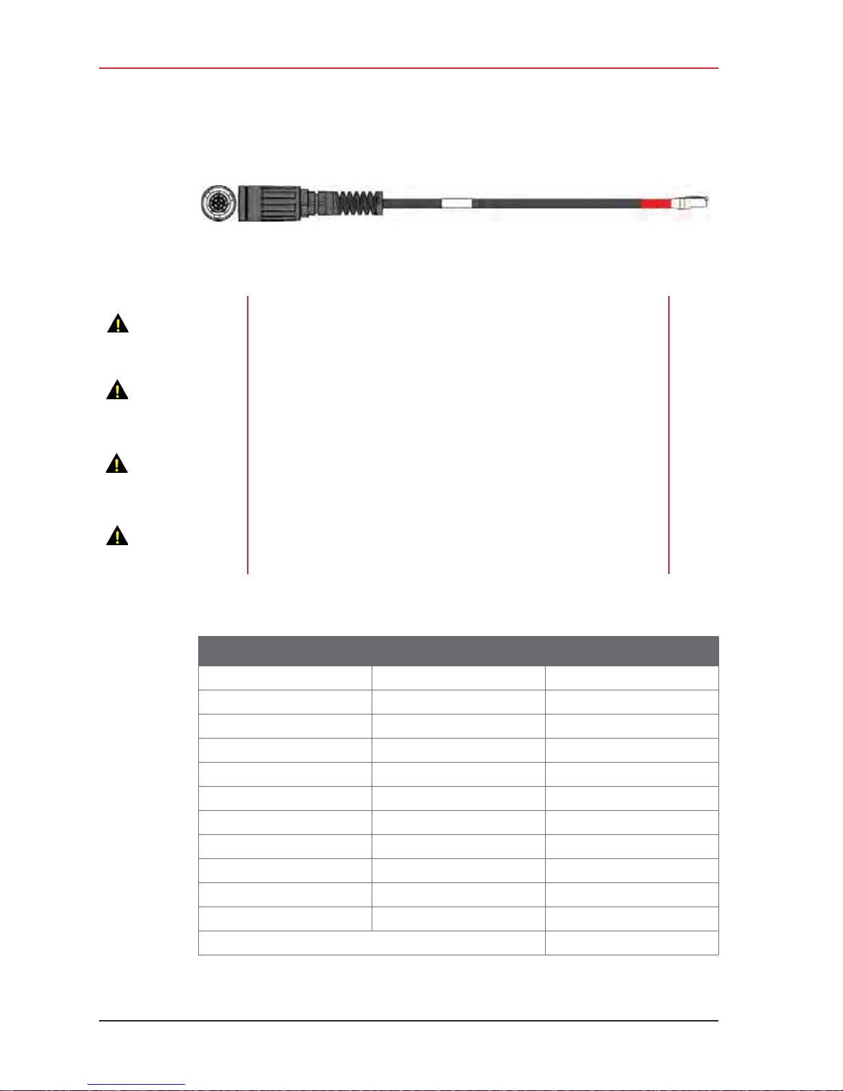
Figure 3–15 Cable, LIU to NanoStation Radio (60-0036)
The LIU to Radio cable is a powered Ethernet Cable. Do not plug it into
the Ethernet port on a Laptop computer when troubleshooting the
radios. Use a non-powered Ethernet cable to avoid damaging the
computer.
Le câble interface de ligne (LIU) à radio est un câble Ethernet alimenté.
Ne le branchez pas au port Ethernet d’un ordinateur portable lors du
dépannage des radios. Afin de ne pas endommager l’ordinateur, utilisez
un câble Ethernet non alimenté.
Das LIU-Radiokabel ist ein mit Strom versorgtes Ethernetkabel. Stecken
Sie es nicht in den Ethernetanschluss in Ihrem Laptop, wenn Sie
Störungen Ihrer Radiosender beseitigen. Benutzen Sie ein nicht mit
Strom versorgtes Ethernetkabel, um eine Beschädigung Ihres
Computers zu vermeiden.
Kabel LIU-radio to zasilany kabel Ethernet. Podczas rozwiązywania
problemów z dziaáaniem urządzeĔ radiowych nie naleĪy podáączaü go do
portu Ethernet w laptopie. Aby uniknąü uszkodzenia komputera, naleĪy
uĪyü niezasilanego kabla Ethernet.
Table 3–7 Cable Pinout, to NanoStation Radio(60-0036)
14-Pin Connector RJ-45 Connector Signal Name
B1TX+
A2TXC3RX+
H 4 POSITIVE
F 5 POSITIVE
D6RXE 7 RETURN
L 8 RETURN
P — SHIELD DRAIN
R* NC —
M* NC —
46 RT System 2 v2.3 Deployment Guide R01.i
© 2010-2014 Wireless Seismic, Inc. All rights reserved.
* Jumper R and M together.
Page 47
Backhaul Components
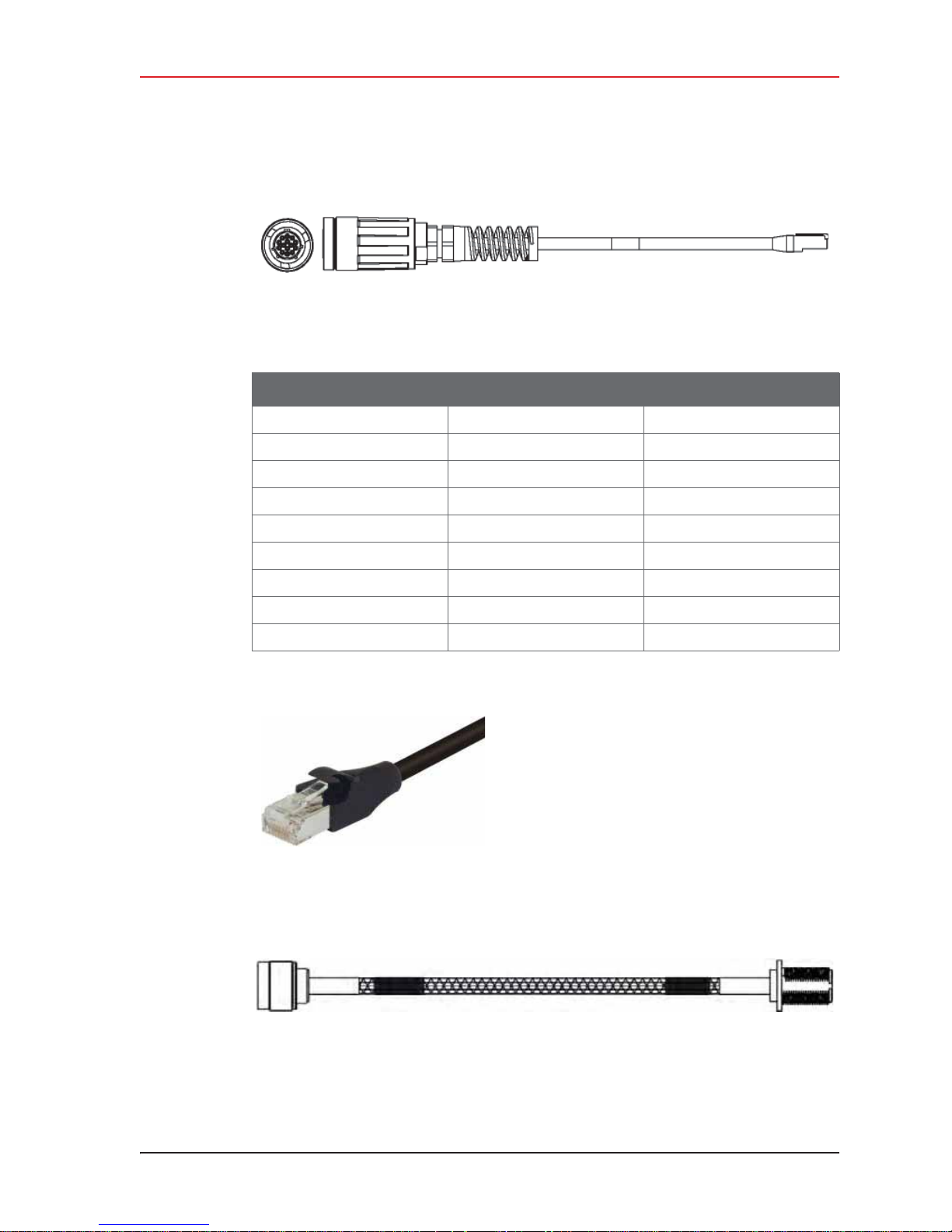
Figure 3–16 Cable, LIU-to-PC (60-0039)
Table 3–8 Cable Pinout, LIU-to-PC (60-0039)
14-Pin Connector RJ-45 Connector Signal Name
B1TX +
A2TX C3RX +
NC 4 POSITIVE
3. Backhaul
NC 5 POSITIVE
D6RX NC 7 RETURN
NC 8 RETURN
P — SHIELD DRAIN
Figure 3–17 Cable, Ethernet, 3 ft
Shielded (65-0104)
R01.i RT System 2 v2.3 Deployment Guide 47
Figure 3–18 Cable, Armored Ethernet, 10 ft (60-0053)
© 2010-2014 Wireless Seismic, Inc. All rights reserved.
Page 48
3. Backhaul
Backhaul Components
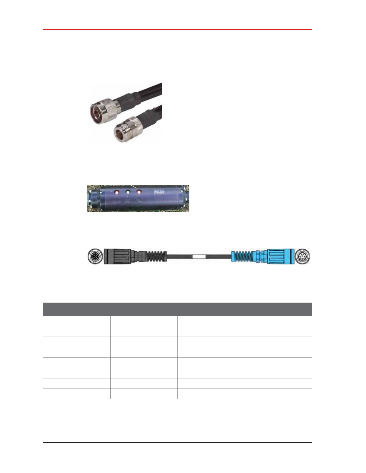
Figure 3–19 Cable, RF
Extender, 10 ft (65-0103)
Figure 3–20 Media Converter (60-0017)
Figure 3–21 Cable, Backhaul Jumper (60-0033)
Table 3–9 Cable Pinout, Backhaul Jumper (60-0033)
14-Pin Connector Wire Color 8-Pin Connector Signal Name
BWHT/ORGATX +
AORGBTX CWHT/GRNCRX +
HBLUDPWR +
FWHT/BLUEPWR +
DGRNFRX EWHT/BRNGGND
LBRNHGND
48 RT System 2 v2.3 Deployment Guide R01.i
© 2010-2014 Wireless Seismic, Inc. All rights reserved.
Page 49
Backhaul Components
Table 3–9 Cable Pinout, Backhaul Jumper (60-0033)
14-Pin Connector Wire Color 8-Pin Connector Signal Name
R* RED NC —
M* NC —
* Install a 1.5 inch long jumper wire between pins R and M
WHT = White, ORG = Orange, GRN = Green, BLU = Blue, BRN = Brown, BLK= Black, YEL = Yellow
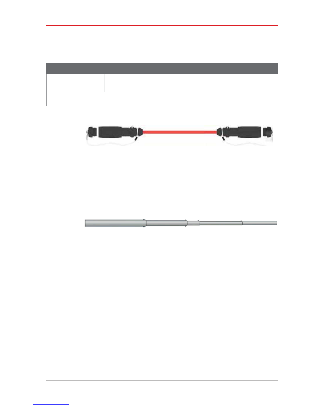
Figure 3–22 Cable, Fiber Optic, Armored, 250 m (60-0026)
3.2.9 Mast and Base
The line and recorder backhauls use the same mast kit components.
3. Backhaul
3.2.9.1 Telescoping Mast
Telescoping backhaul masts are used to elev ate th e backhaul component s abov e obstruct ions
and to enable radio communications to accommodate typical cross-line distances. The mast
is stabilized with guy ropes. The following figure shows the mast:
3.2.9.2 Base
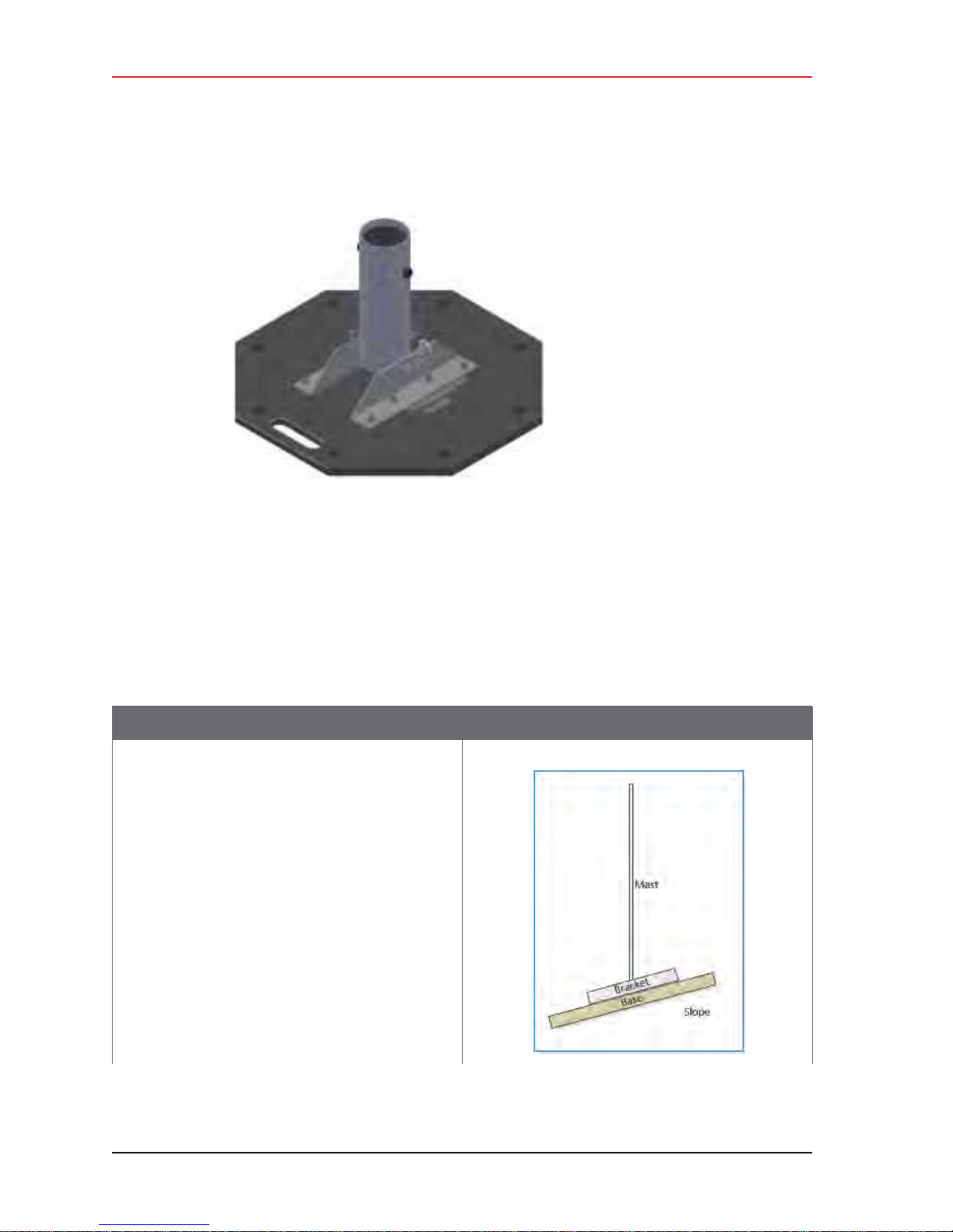
The base (shown in the following figure) stabilizes the mast that is attached to the hinged
mast sleeve. The base is staked into the ground for added stability.
Figure 3–23 Mast (55-0050)
R01.i RT System 2 v2.3 Deployment Guide 49
© 2010-2014 Wireless Seismic, Inc. All rights reserved.
Page 50
3. Backhaul
Setting up the Backhaul
Figure 3–24 Base (55-0050)
The Weighted Base (70-0070) is another option for use when staking is impractical (see “E.
Weighted Base” on page 182).
3.3 Setting up the Backhaul
This section provides instructions on how to assemble the backhaul components.
Table 3–10 How to Set Up the Backhaul
Step Image
1 Gather all of the backhaul components.
2 Refer to the deployment instructions to
determine the location and compass heading to
the next back haul site closer to central.
3 Use the compass to determine and mark that
direction.
4 Use the following considerations while
positioning the base:
Ɣ Locate the base such that the guy lines and
the mast clear obstructions during erection
and while in operation.
Ɣ If the ground is sloped, position the base
such that when the base is flush to the
ground, the bracket orientation allows the
mast to remain perpendicular to the ground.
50 RT System 2 v2.3 Deployment Guide R01.i
© 2010-2014 Wireless Seismic, Inc. All rights reserved.
Page 51
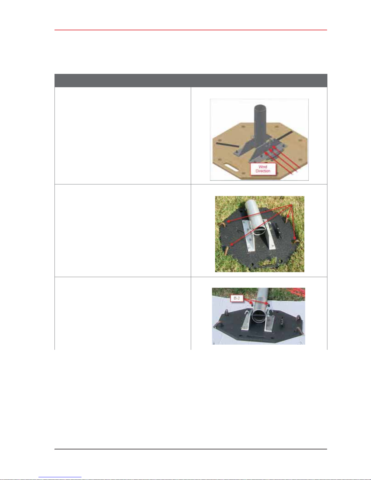
Table 3–10 How to Set Up the Backhaul
Step Image
Ɣ If the wind is blowing, the mast is more
stable when the brackets are perpendicular
to the wind.
5 Secure the base [B-1] to the ground with stakes
[BK-4] or nails [BK-6].
3. Backhaul
Setting up the Backhaul
6 Attach the mast [M-3] to the base [B-1].
Tighten both knobs [B-2].
R01.i RT System 2 v2.3 Deployment Guide 51
© 2010-2014 Wireless Seismic, Inc. All rights reserved.
Page 52
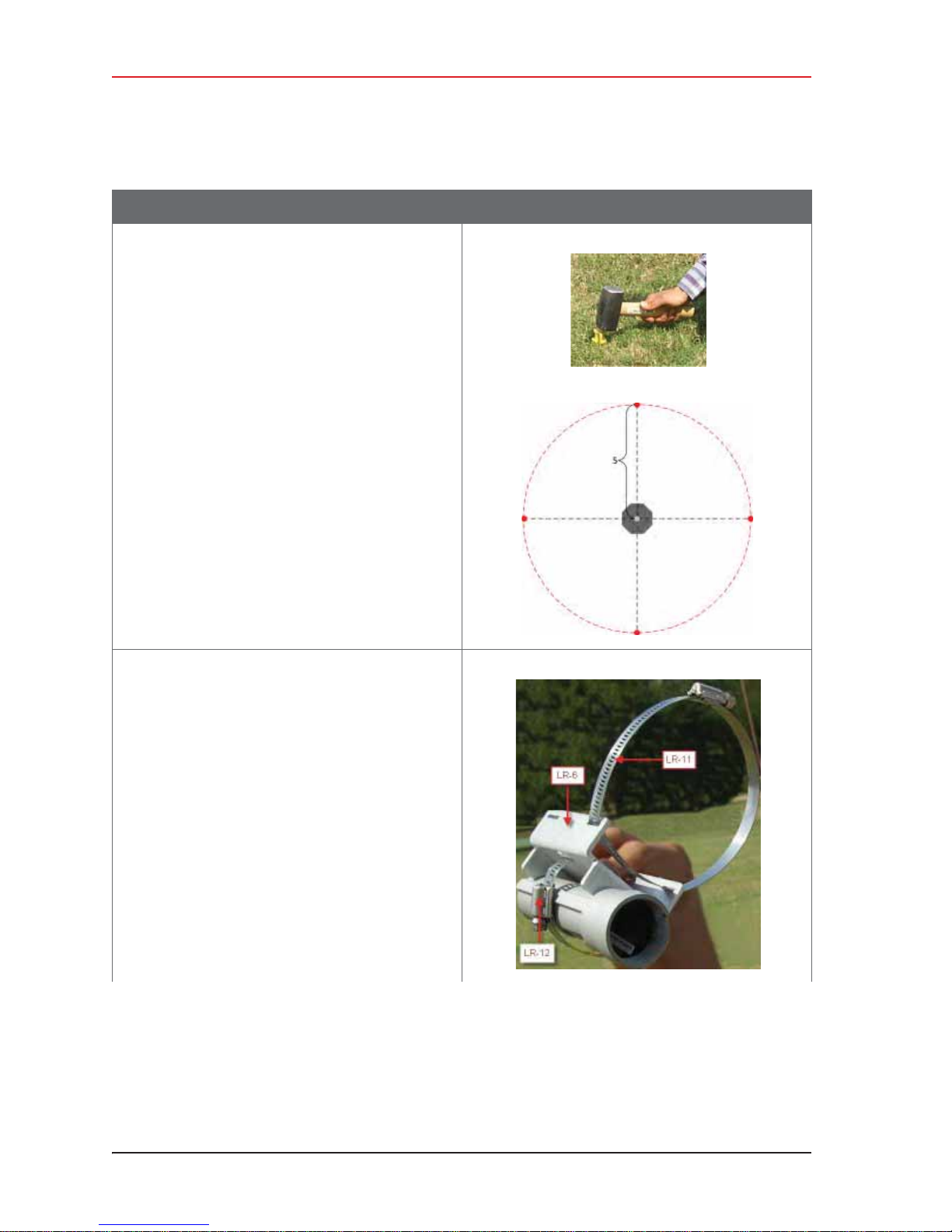
3. Backhaul
Setting up the Backhaul
Table 3–10 How to Set Up the Backhaul
Step Image
7 Position four stakes equal distances apart at
approximately 20 ft (6 m) from the base. Pound
them into the ground.
8 Assemble the radios and brackets:
Ɣ Bullet line radio installation – Assemble the
Bullet radios and brackets.
Ź Insert the 4 in hose clamp [LR -11] in the
side slots of the bracket [LR-6].
Ź Insert the 2 in hose clamp [LR -12] in the
center slots of the bracket [LR-6].
Ź Insert the line radio between the bracket
[LR-6] and the 2 in hose clamp [LR-12].
Ź Tighten the 2 in hose clamp
[LR-12]around the radio.
Line radio in bracket:
52 RT System 2 v2.3 Deployment Guide R01.i
© 2010-2014 Wireless Seismic, Inc. All rights reserved.
Page 53
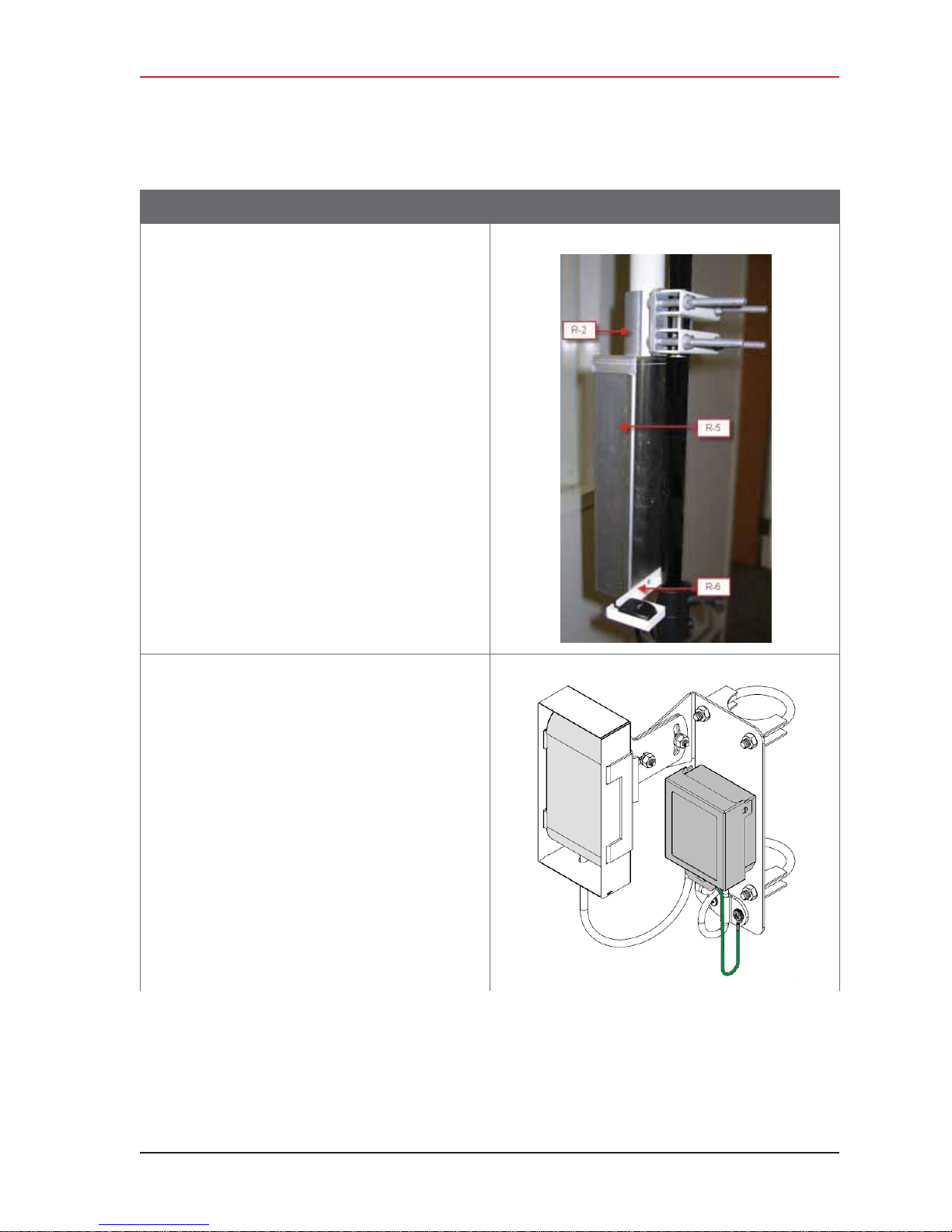
Table 3–10 How to Set Up the Backhaul
Step Image
3. Backhaul
Setting up the Backhaul
Ɣ Rocket radio installation – The Rocket radio,
antennas, and bracket are already
assembled.
Ɣ NanoStation radio installation – The
NanoStation radio, surge protector, and
bracket are already assembled.
Recorder radio in bracket:
R01.i RT System 2 v2.3 Deployment Guide 53
© 2010-2014 Wireless Seismic, Inc. All rights reserved.
Page 54
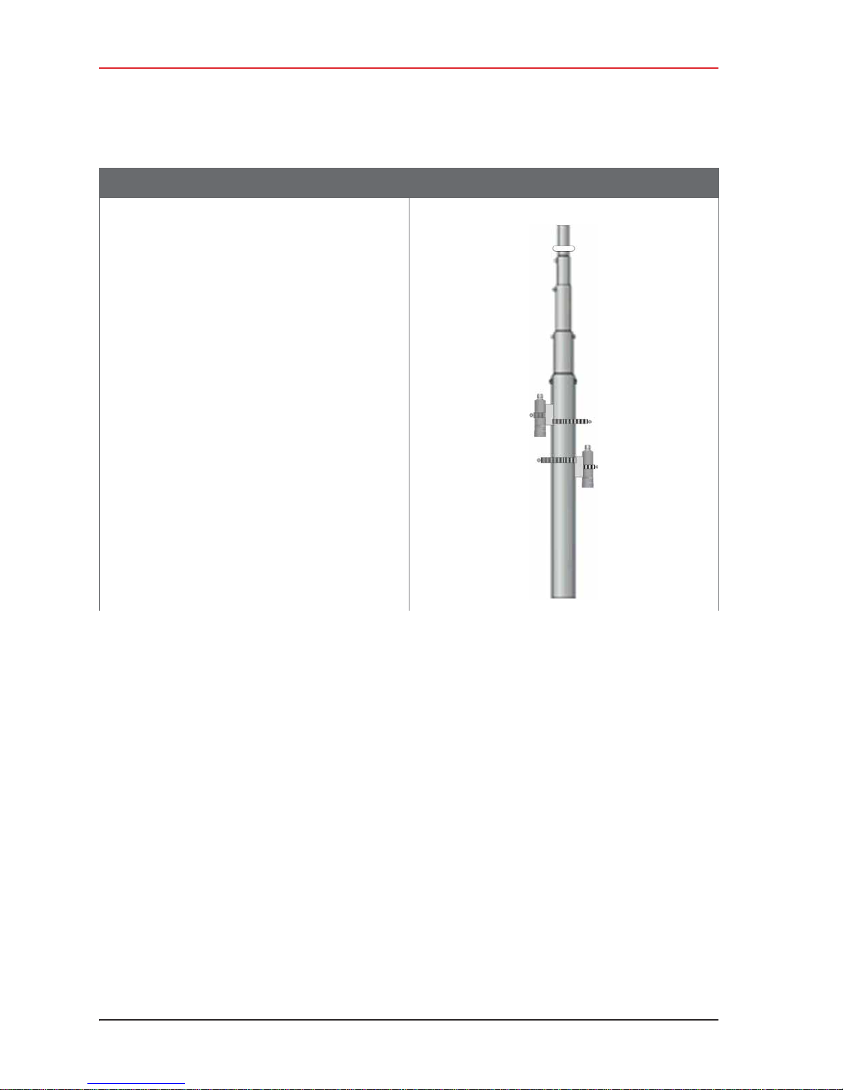
3. Backhaul
Setting up the Backhaul
Table 3–10 How to Set Up the Backhaul
Step Image
9 Assemble the mast:
Ɣ Bullet radio installation – While the mast is
resting on the ground, slide the following on
the mast:
Ź Bullet radios and clamps (do not tighten)
Ź Mast guy ring [M-4]
54 RT System 2 v2.3 Deployment Guide R01.i
© 2010-2014 Wireless Seismic, Inc. All rights reserved.
Page 55
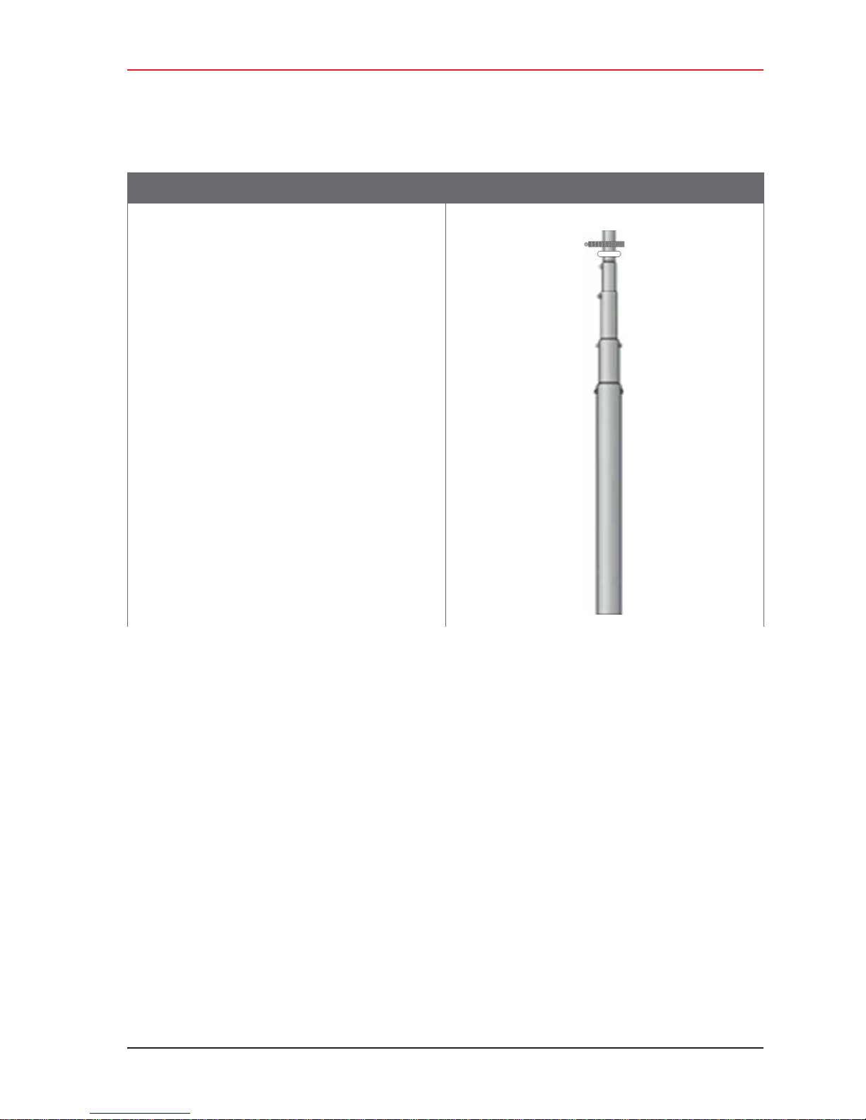
Table 3–10 How to Set Up the Backhaul
Step Image
Ɣ Rocket radio installation – While the mast is
resting on the ground, slide the following on
the mast:
Ź Mast guy ring [M-4]
Ź Surge Protector cable clamp (do not
tighten)
3. Backhaul
Setting up the Backhaul
R01.i RT System 2 v2.3 Deployment Guide 55
© 2010-2014 Wireless Seismic, Inc. All rights reserved.
Page 56
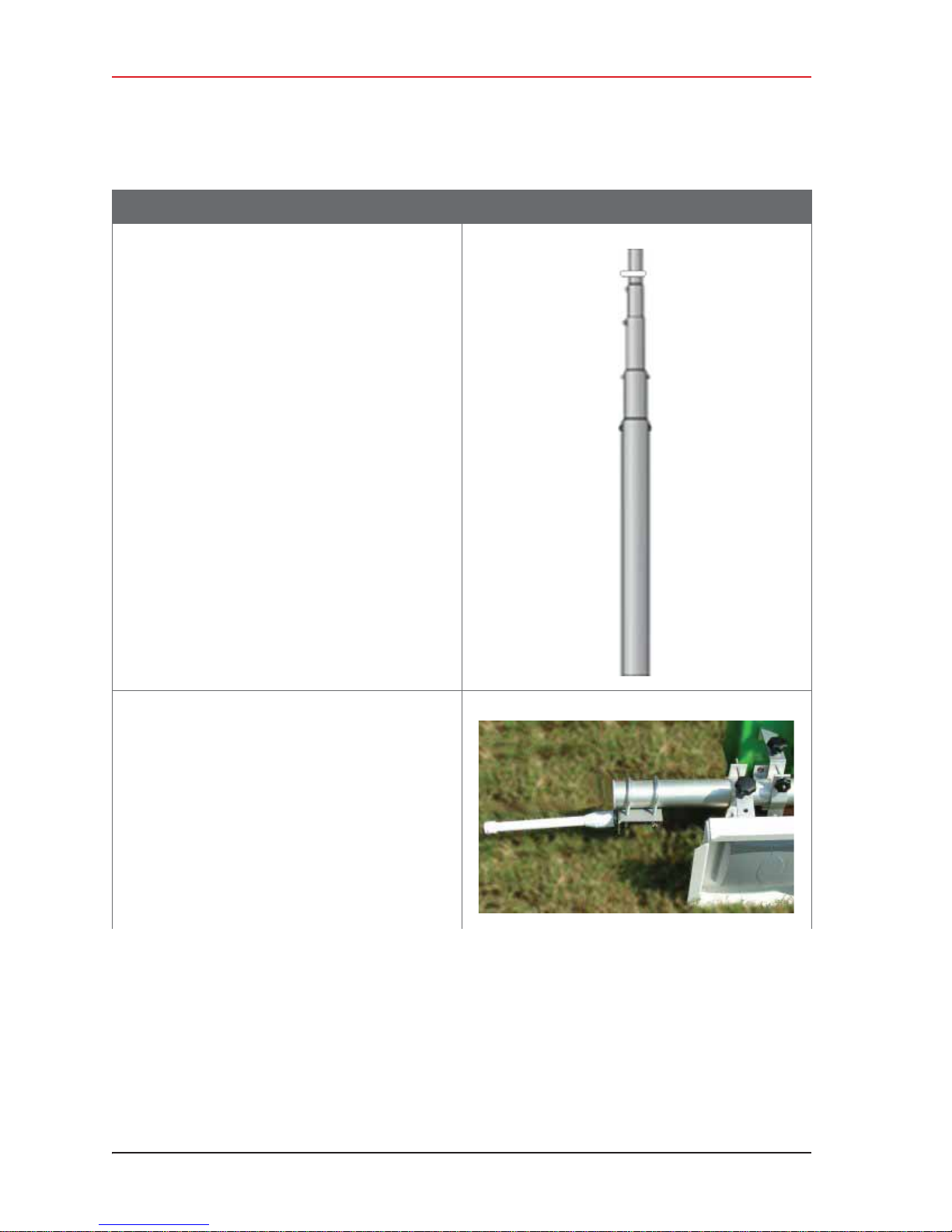
3. Backhaul
Setting up the Backhaul
Table 3–10 How to Set Up the Backhaul
Step Image
Ɣ NanoStation radio installation – While the
mast is resting on the ground, slide the
following on the mast:
Ź Mast guy ring [M-4]
10 Attach and tighten the following:
Ɣ Bullet radio installation:
Ź Bullet radio antenna brackets and
antennas [LR-4, LR-5]
Ź Omni antenna bracket [M-5] and
antenna [LR-3]
56 RT System 2 v2.3 Deployment Guide R01.i
© 2010-2014 Wireless Seismic, Inc. All rights reserved.
Page 57
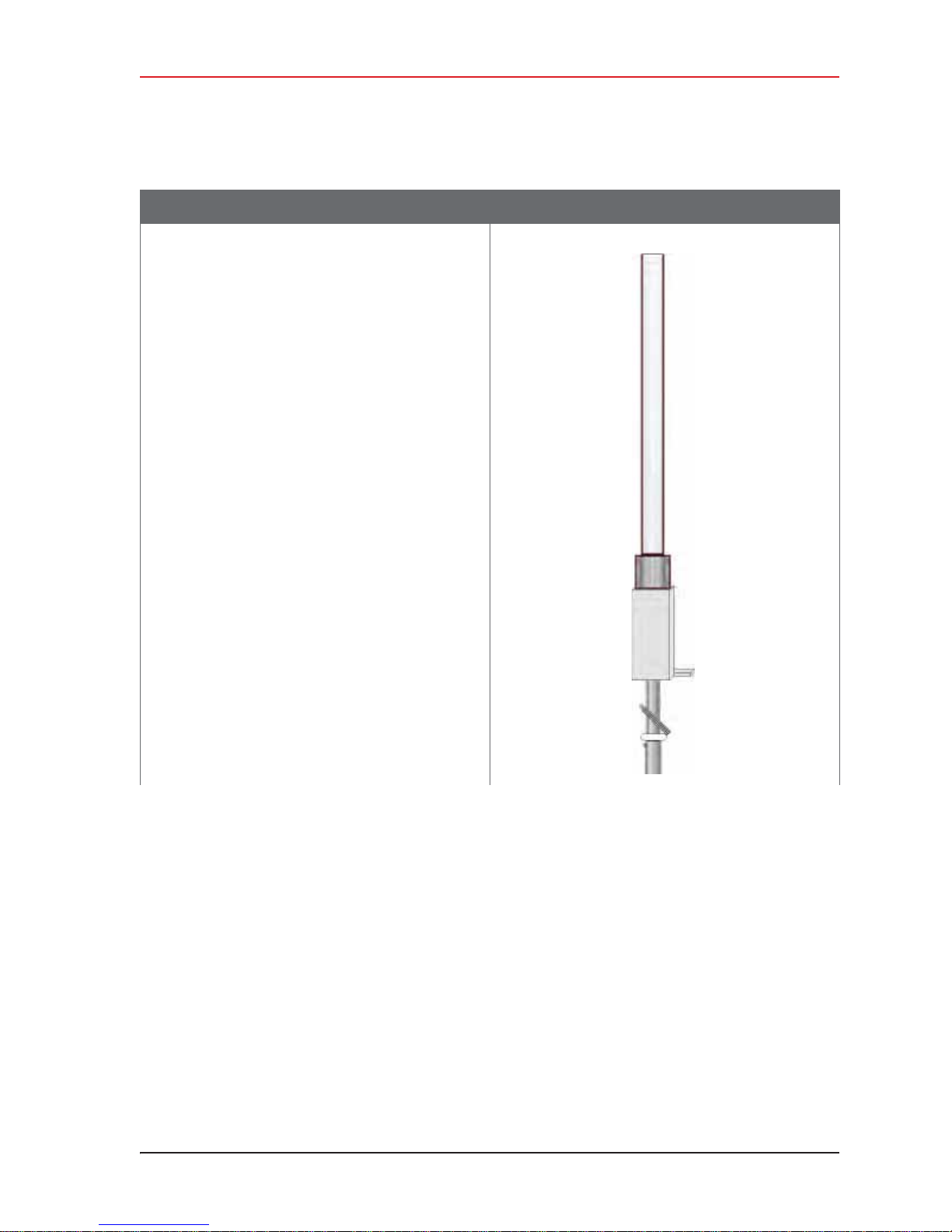
Table 3–10 How to Set Up the Backhaul
Step Image
Ɣ Rocket radio installation – Attach the Rocket
radio antenna and bracket [R-2] to the
mast.
3. Backhaul
Setting up the Backhaul
R01.i RT System 2 v2.3 Deployment Guide 57
© 2010-2014 Wireless Seismic, Inc. All rights reserved.
Page 58
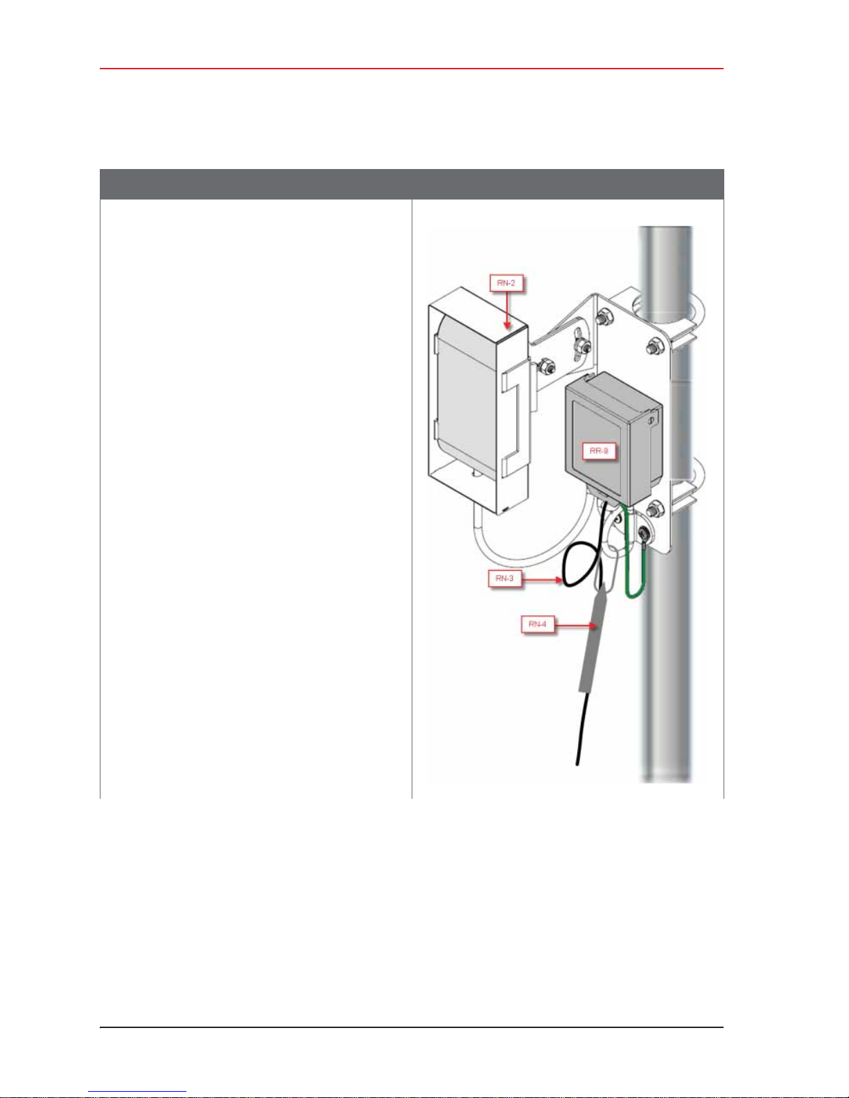
3. Backhaul
Setting up the Backhaul
Table 3–10 How to Set Up the Backhaul
Step Image
Ɣ NanoStation radio installation – Attach the
NanoStation radio bracket assembly [RN-2]
to the mast.
58 RT System 2 v2.3 Deployment Guide R01.i
© 2010-2014 Wireless Seismic, Inc. All rights reserved.
Page 59
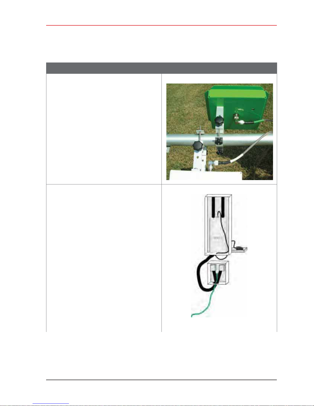
Table 3–10 How to Set Up the Backhaul
Step Image
11 Attach the cables:
Ɣ Bullet radio installation – Attach an elbow
connector [LR-14] to the antenna and then
an armored cable [LR-7, LR-8] to the elbow
connector.
Match white-to-white and green-to-green if
your panels are color-coded.
3. Backhaul
Setting up the Backhaul
Ɣ Rocket radio installation:
Ź Open the protective metal case if the
Ethernet cable is not already attached.
Ź Connect the GPS antenna if it is not
already connected.
Ź Connect a short Ethernet cable [R-8] to
the radio [R-3].
Ź Close the protective metal case.
Ź Open the surge protector case [R-9].
Ź Remove the rubber grommet from the
surge protector case and cut some slots
in it.
Ź Thread two Ethernet cables [R-8, R-10]
and a ground wire [BK-14] through the
grommet and place the grommet back in
the case.
Ź Plug the Ethernet cables into the
shielded RJ45 jacks. It does not matter
which cable goes to which jack; the unit
provides bidirectional protection.
Ź Attach the ground wire to the ground
lug.
Ź Close the surge protector case and
secure it to the mast with the hose
clamp.
R01.i RT System 2 v2.3 Deployment Guide 59
© 2010-2014 Wireless Seismic, Inc. All rights reserved.
Page 60
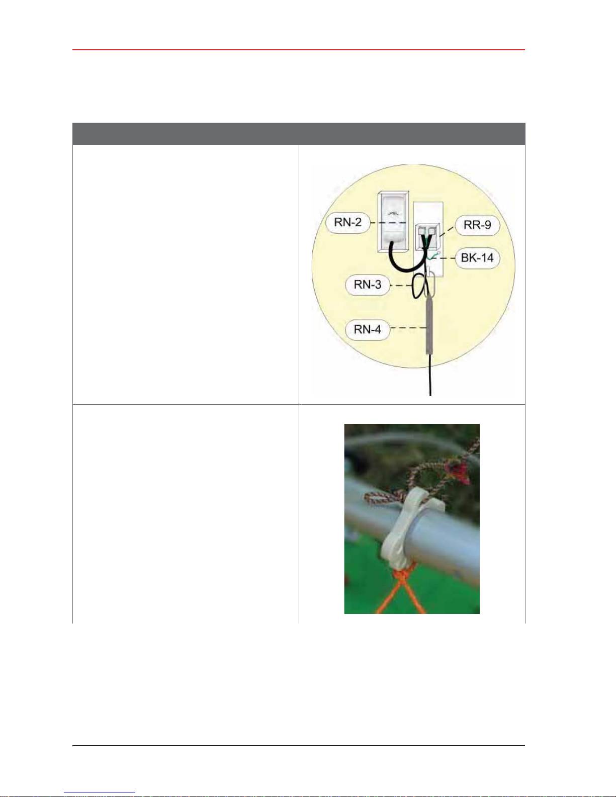
3. Backhaul
Setting up the Backhaul
Table 3–10 How to Set Up the Backhaul
Step Image
Ɣ NanoStation radio installation:
Ź Open the surge protector case [R-9].
Ź Remove the grommet from the case.
Ź Thread the Ethernet cable [RN-3],
through the grommet with the short
Ethernet cable (that is attached to the
redound the ground wire [BK-14]. Place
the grommet back in the case.
Ź Plug the Ethernet cable into the shielded
RJ45 jacks. It does not matter which
cable goes to which jack; the unit
provides bidirectional protection.
Ź Close the surge protector case.
Ź Attache the strain relief [RN-4] to the D-
ring on the bracket.
Ź Loop the Ethernet Cable [RN-3] through
the strain relief [RN-4].
12 Attach the guy lines to the mast collar.
NOTE: Use a taut-line-hitch knot for best results (see
“G. Rope Knot” on page 188).
60 RT System 2 v2.3 Deployment Guide R01.i
© 2010-2014 Wireless Seismic, Inc. All rights reserved.
Page 61
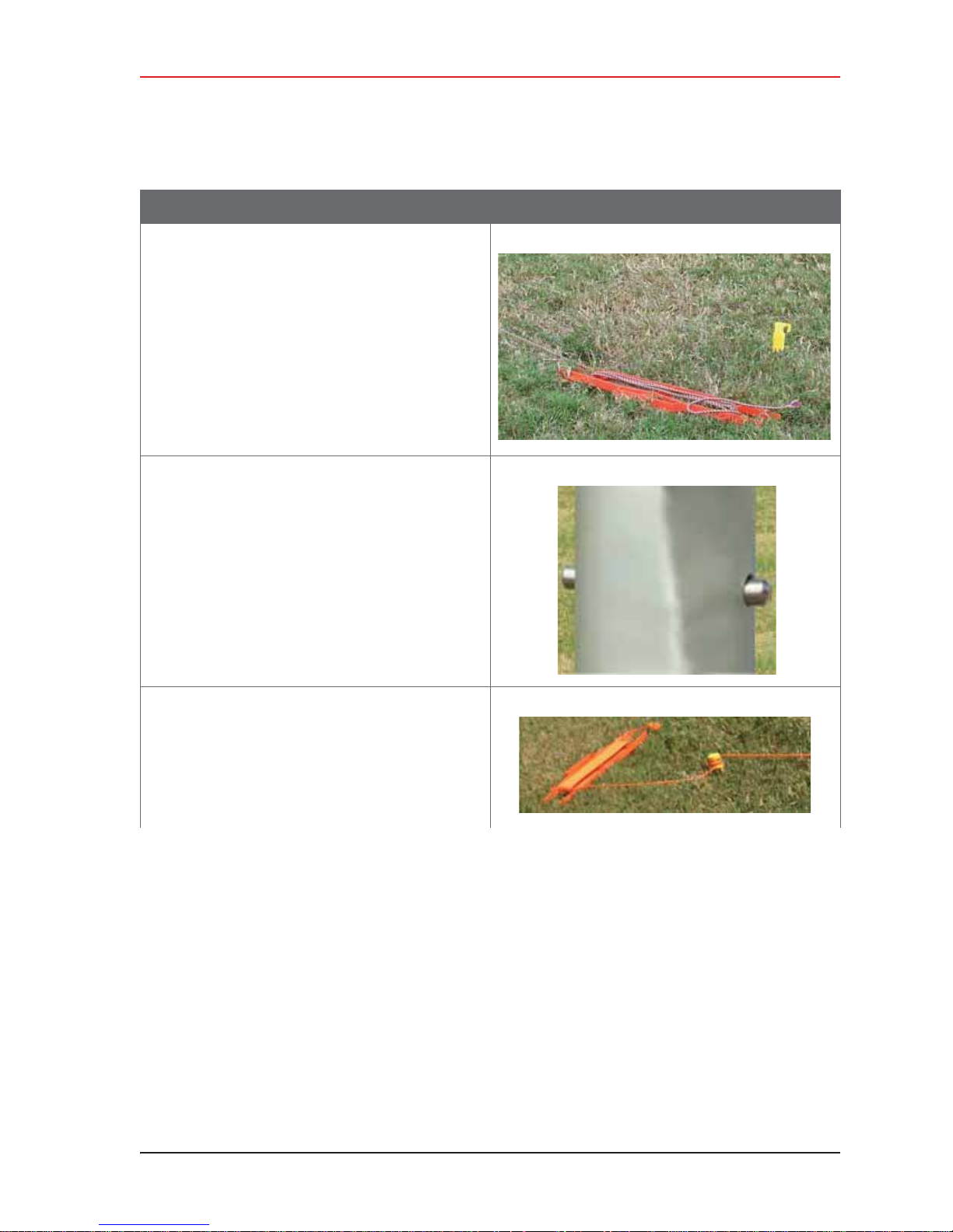
Table 3–10 How to Set Up the Backhaul
Step Image
13 Lay out the four guy lines close to the stakes.
14 Extend the mast, clicking the segments into
place.
3. Backhaul
Setting up the Backhaul
15 Attach the guy lines to the stakes.
NOTE: Use a taut-line-hitch knot for best results (see
“G. Rope Knot” on page 188).
R01.i RT System 2 v2.3 Deployment Guide 61
© 2010-2014 Wireless Seismic, Inc. All rights reserved.
Page 62

3. Backhaul
Setting up the Backhaul
Table 3–10 How to Set Up the Backhaul
Step Image
16 Walk the mast to an upright position.
17 While one person holds the mast, a second
person tightens the guy lines evenly. Keep the
mast level/vertical (use the level included with
the kit).
18 If assembling the Bullet radio backhaul:
a Attach the cables from the antennas to the
top of the Bullet radios.
62 RT System 2 v2.3 Deployment Guide R01.i
© 2010-2014 Wireless Seismic, Inc. All rights reserved.
Page 63
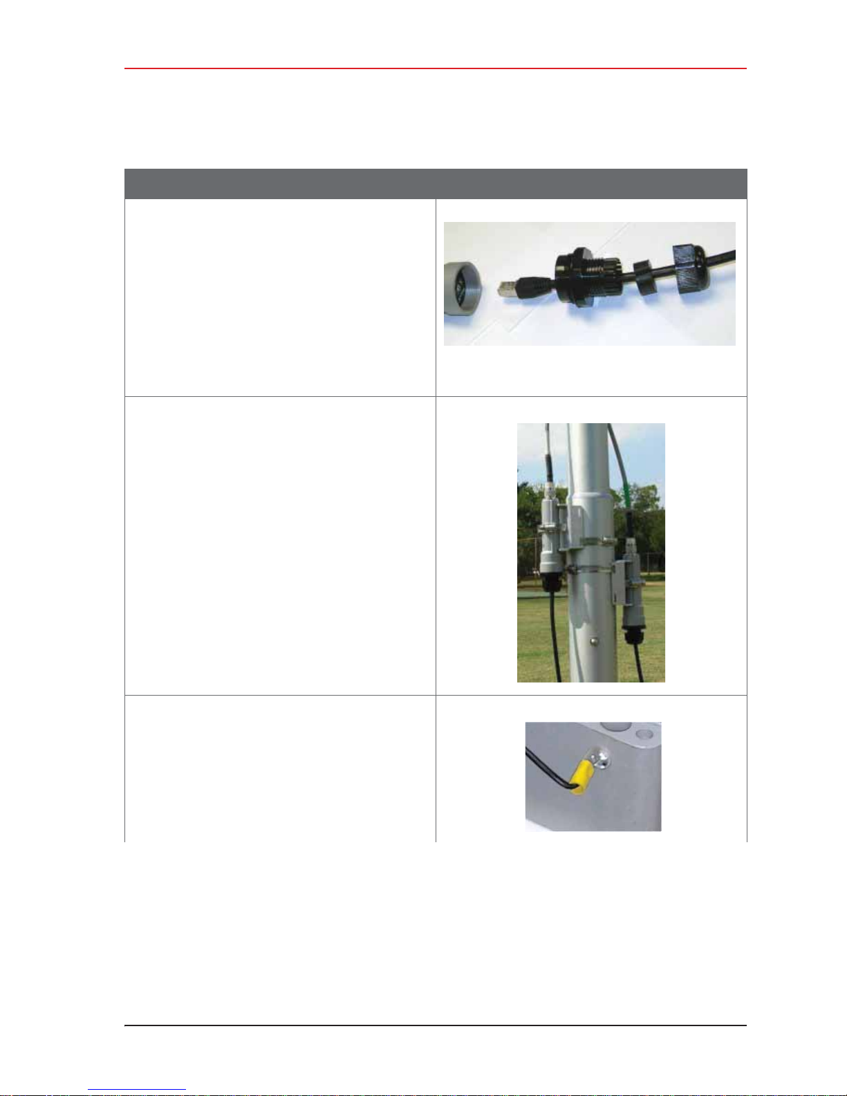
Table 3–10 How to Set Up the Backhaul
Step Image
b Attach the cables to the bottom end of the
Bullet radios.
Ź Assemble the connector for the radio as
shown in the image to the right:
Ź Plug the Ethernet connector into the
radio.
Ź Screw the large coupler into the base of
the radio. Hand-tighten only.
Ź Push the rubber grommet into the base
of the large coupler.
Ź Screw the end cap on the large coupler.
Hand-tighten only.
c Tighten the clamps on the Bullet radios.
Ź Verify that the armored cables attached
to the antennas are straight and not
twisted.
Ź Position the line radio so the armored
cable is not pulling on the antenna.
Ź Tighten the cable clamp.
3. Backhaul
Setting up the Backhaul
19 Set up the LIU:
Ɣ Ground the LIU – Verify that the LIU is
grounded. Attach a ground wire to the case,
and to a nail that is driven into the ground.
Attach the LIU ground wire and the Surge
Protector ground wire to the same nail.
R01.i RT System 2 v2.3 Deployment Guide 63
© 2010-2014 Wireless Seismic, Inc. All rights reserved.
Page 64
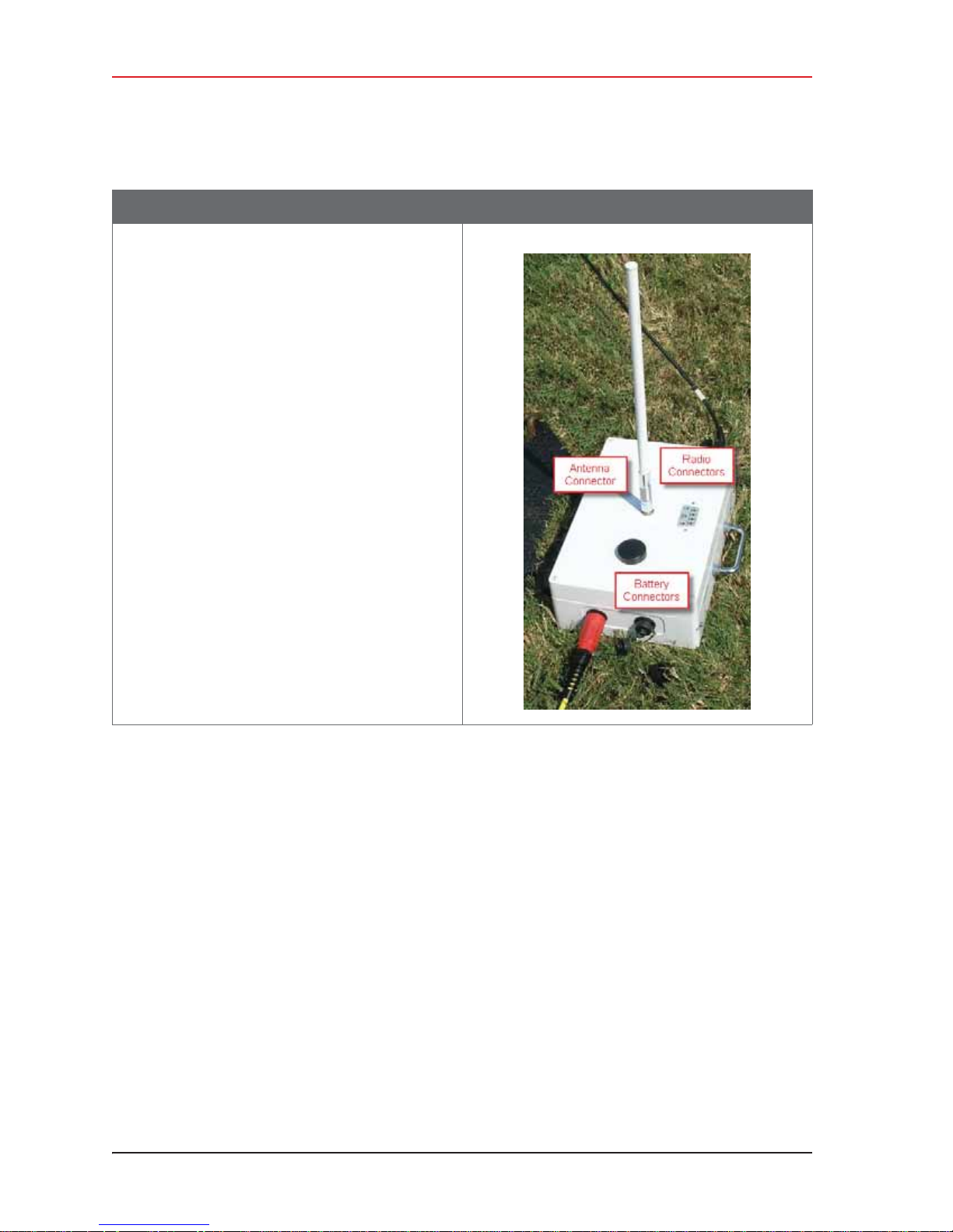
3. Backhaul
Setting up the Backhaul
Table 3–10 How to Set Up the Backhaul
Step Image
Ɣ Attach the radio cables to the LIU.
Ɣ Attach the antenna to LIU.
Ɣ Attach the battery to the LIU.
64 RT System 2 v2.3 Deployment Guide R01.i
© 2010-2014 Wireless Seismic, Inc. All rights reserved.
Page 65
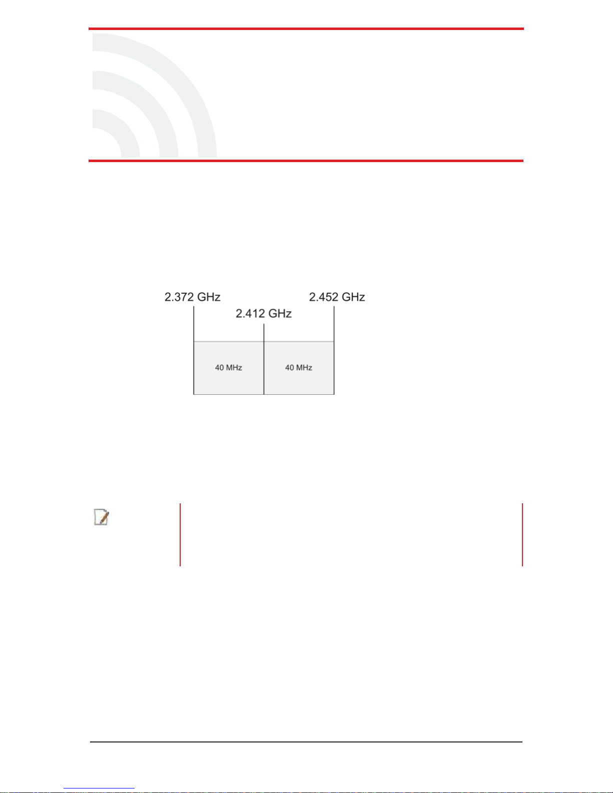
4.1 Overview
The backhaul is composed of a number of line station mast/radio/LIUs. The number of
poles pole (masts/towers) in your point-to-point spread must be a multiple of the
number of channels used.
A channel is an 80 MHz wide frequency band with 40 MHz on either side of the center
frequency. For example, if the center frequency is 2.412 GHz, the frequency range for
that channel is 2.372 to 2.452 GHz.
4
4. Point-to-Point Backhaul
NOTE
Figure 4–1 Channel – 80 MHz Wide Frequency
Band
When using a system with six possible channels, the backhaul could have just 6 poles,
or a multiple of 6 poles: 6, 12, 18, 24, and so on.
This section uses an example of six possible channels, and 18 line station mast/radio/
LIUs. Each pole (mast/tower) has two radios and one LIU as shown in the following
figure.
If using the mast at the recording truck, connect the LIU with an Ethernet or
Fiber cable to the recording truck. If the mast is not used at the recording truck,
the connections shown in the figure to the recording truck are not used.
See “Connecting to the Recording Truck” on page 92 for a radio link (pendant)
option).
RT System 2 v2.3 65 Deployment Guide R01.i
© 2010-2014 Wireless Seismic, Inc. All rights reserved.
Page 66
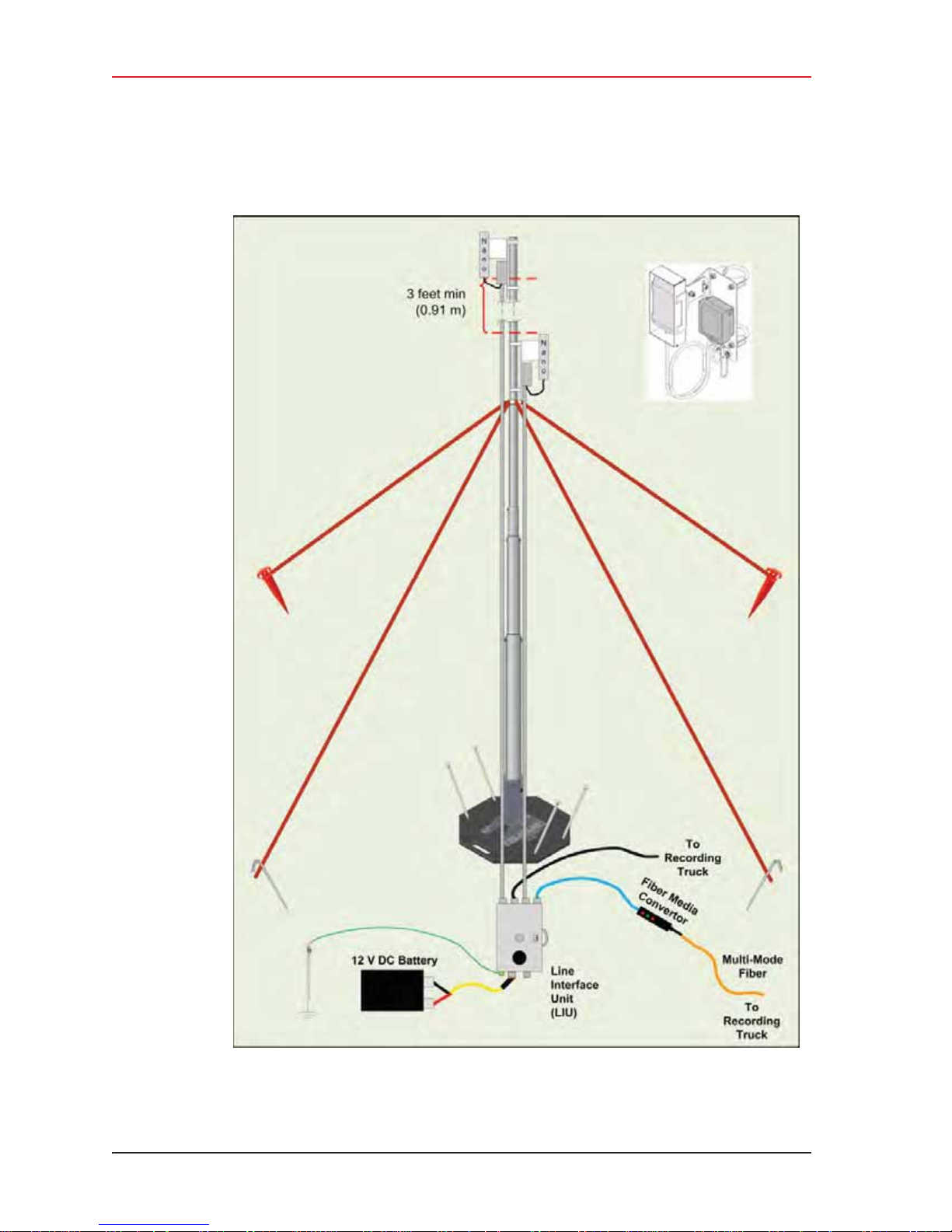
4. Point-to-Point Backhaul
Overview
66 RT System 2 v2.3 Deployment Guide R01.i
© 2010-2014 Wireless Seismic, Inc. All rights reserved.
Figure 4–2 Line Station Backhaul
Page 67
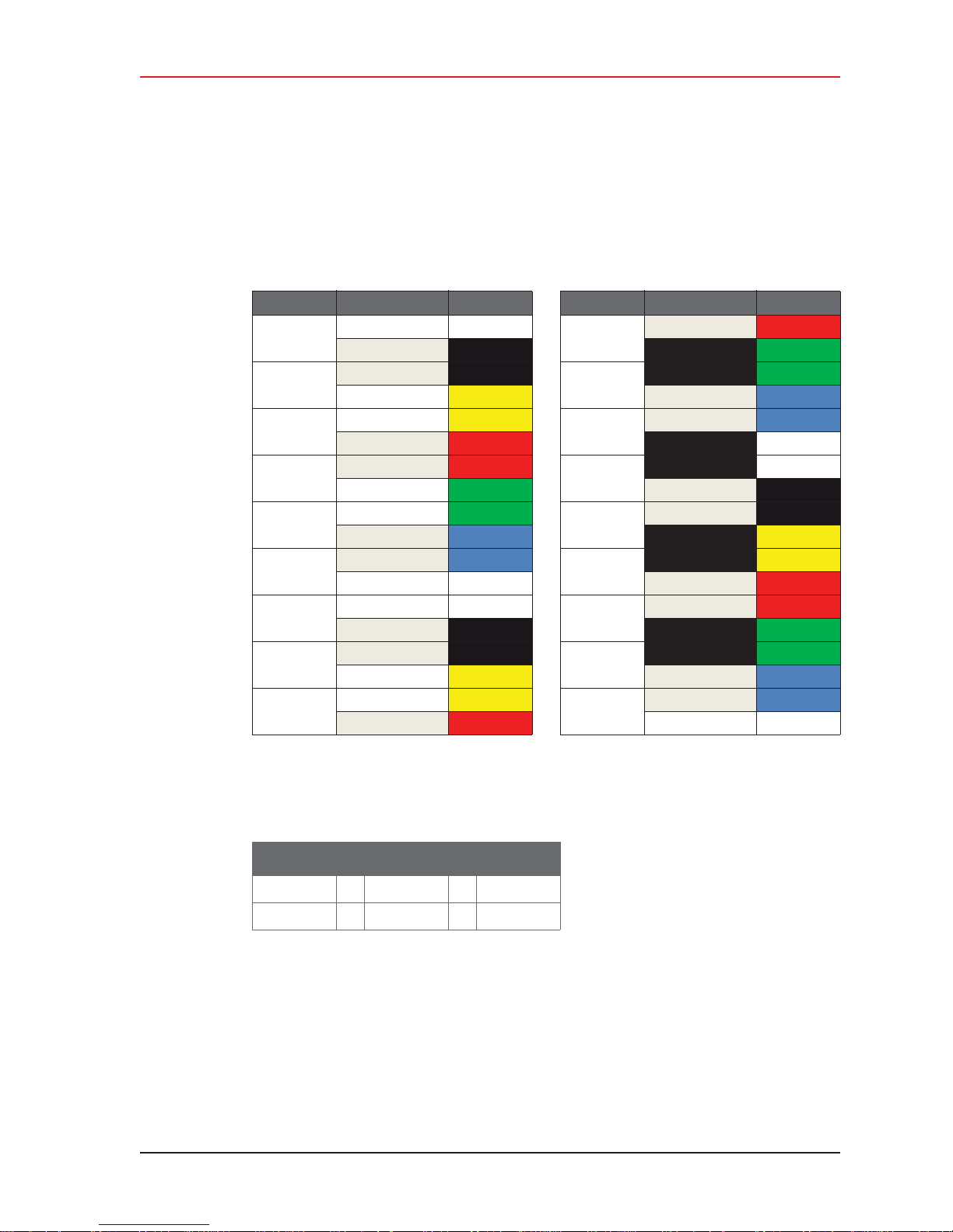
4. Point-to-Point Backhaul
Overview
The radios are configured as pairs and are either an Access Point (A) or a Station (S).
An Access Point communicates only with a Station. An Access Point cannot communicate with
an Access Point, and a Station cannot communicate with a Station.
The poles (masts) and radios for a six-channel system are labeled and color-coded as
follows. The number of colors used should match the number of channels used.
Pole Radio Color Pole Radio Color
Pole 1
Pole 2
Pole 3
Pole 4
Pole 5
Pole 6
Pole 7
Pole 8
Pole 9
18:S-P1 White
1:A-P1 Black 10:A-P10 Green
1:S-P2 Black
2:A-P2
2:S-P3
3:A-P3 Red 12:A-P12 White
3:S-P4 Red
4:A-P4 Green 13:A-P13 Black
4:S-P5 Green
5:A-P5 Blue 14:A-P14 Yellow
5:S-P6 Blue
6:A-P6 White 15:A-P15 Red
6:S-P7 White
7:A-P7 Black 16:A-P16 Green
7:S-P8 Black
8:A-P8
8:S-P9 Yellow
9:A-P9
Yellow 11:A- P11 Blue
Yellow
Yellow 17:A-P17 Blue
Red 18:A-P18 White
Pole 10
Pole 11
Pole 12
Pole 13
Pole 14
Pole 15
Pole 16
Pole 17
Pole 18
9:S-P10 Red
10:S-P11 Green
11:S-P12 Blue
12:S-P13 White
13:S-P14 Black
14:S-P15 Yellow
15:S-P16 Red
16:S-P17 Green
17:S-P18 Blue
Where:
i Label Nomenclature:
Table 4–1 Label Nomenclature
Pair # : A or S - Pole #
2:A-P2
2:S-P3
i S = Station
i A = Access Point
i The pole pairs must remain in sequential order:
Ɣ Radio 1:A-P1 communicates only with Radio 1:S-P2
Ɣ Radio 2:A-P2 communicates only with Radio 2:S-P3
Ɣ And so on until pole 18, where Radio 18:A-P18 communicates only with Radio 18:S-
P1
R01.i RT System 2 v2.3 Deployment Guide 67
© 2010-2014 Wireless Seismic, Inc. All rights reserved.
Page 68
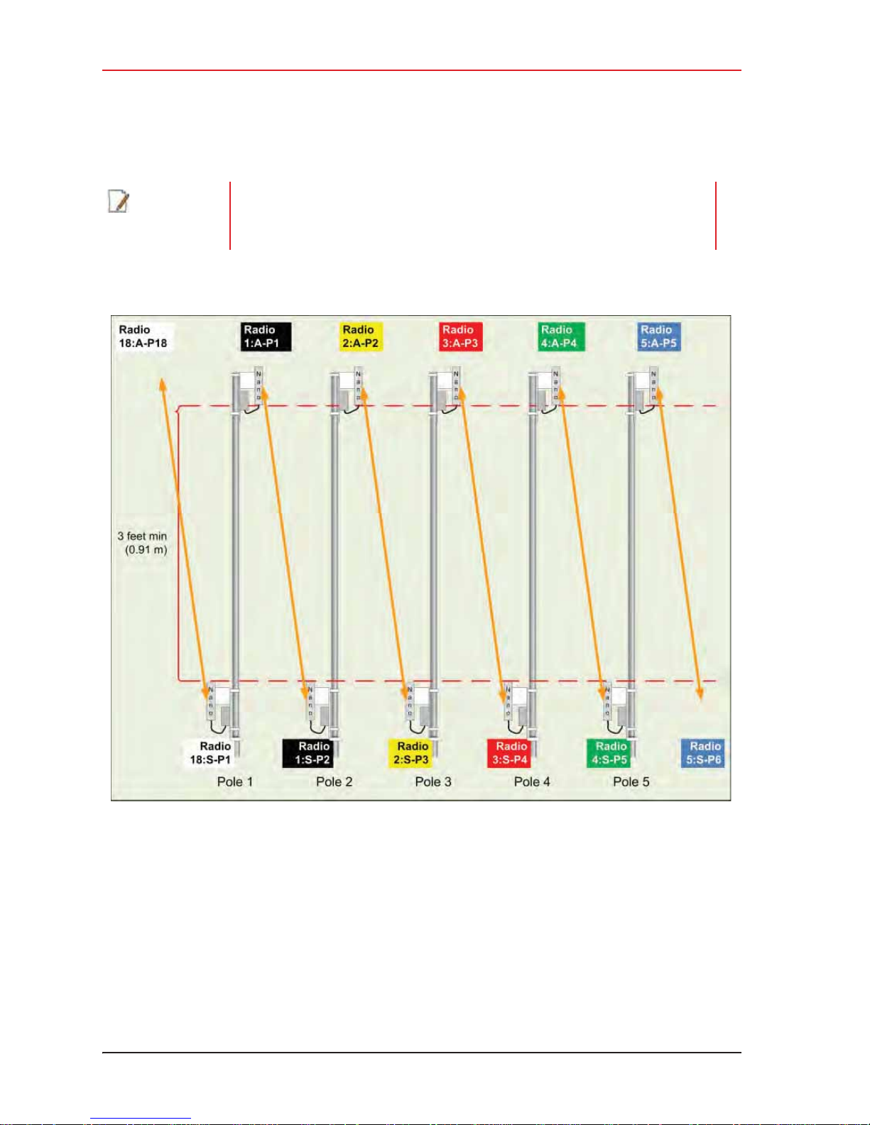
4. Point-to-Point Backhaul
Overview
NOTE
The primary indicator for radio-to-radio communication is the alpha-numeric
label. The colored label is provided as a visual indicator to ensure that the pole is
pointed correctly to the next radio. For example, a yellow radio cannot
communicate with all yellow radios.
Figure 4–3 Radio-to-Radio Communication
In some cases—such as when line-of-sight cannot be established—using fiber cables can
improve communication. Install the radios and poles using the same labels and positioning;
however, only the odd or even pairings are used for radio communication. The other pairings
are linked together with fiber cable as shown in the following figure.
68 RT System 2 v2.3 Deployment Guide R01.i
© 2010-2014 Wireless Seismic, Inc. All rights reserved.
Page 69
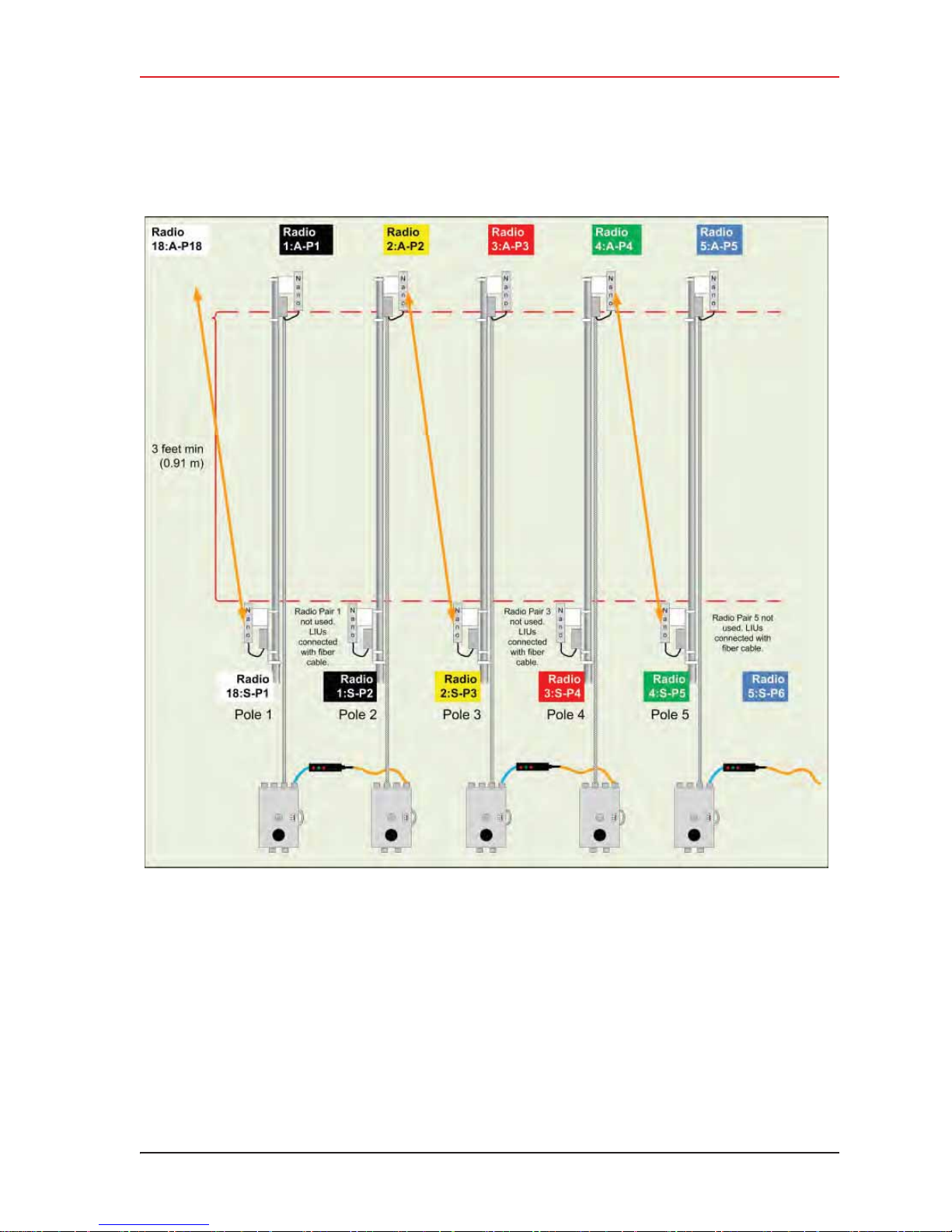
4. Point-to-Point Backhaul
Overview
R01.i RT System 2 v2.3 Deployment Guide 69
Figure 4–4 Radio-to-Fiber Communication
© 2010-2014 Wireless Seismic, Inc. All rights reserved.
Page 70
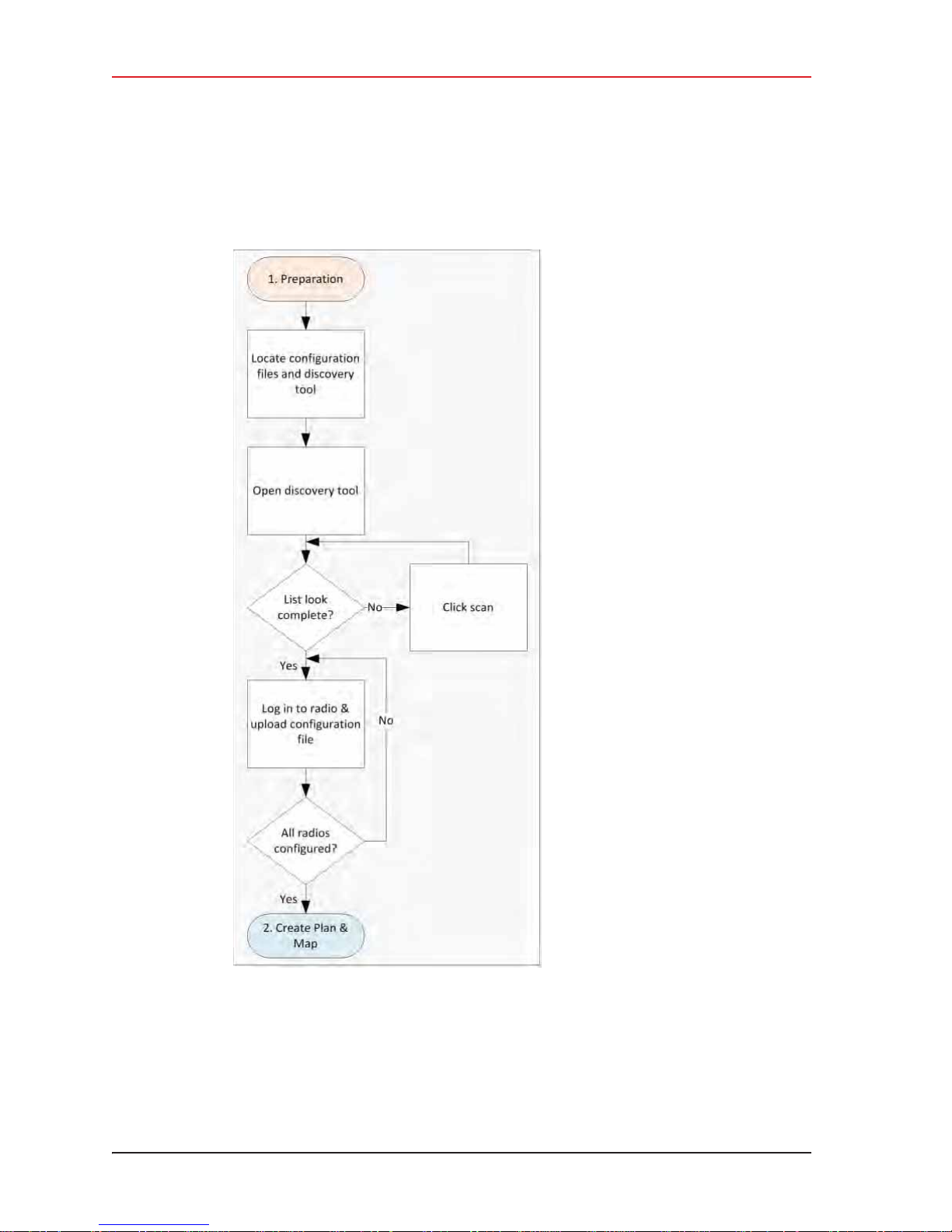
4. Point-to-Point Backhaul
Preparation
4.2 Preparation
This section provides the steps required to prepare the radios for placement in the field.
Figure 4–5 Preparation Troubleshooting Flow
There are two versions of the NanoStation M5 radio. Verify that you are using the correct
radio and configuration files for your location. Wireless Seismic, Inc. recommends using only
the following radios in a point-to-point network.
70 RT System 2 v2.3 Deployment Guide R01.i
© 2010-2014 Wireless Seismic, Inc. All rights reserved.
Page 71

4. Point-to-Point Backhaul
Preparation
i United States frequencies (56-0035 US) – Operating frequency 5745 – 5825 MHz
i International frequencies (56-0032 INTL) – Operating frequency 5470 – 5825 MHz
NOTE
TIP
Operating outside of the allowed frequency range could result in sanctions by
governmental regulatory agencies. Verify that all radios are correct for the
market in which they will be used.
If you use an international configuration file with a United States radio, or a United States
configuration file with an international radio, an error message is displayed:
Figure 4–6 Invalid Country Code Error Message
The ability to modify the Country Code is disabled for radios that are configured for use in
the United States and Canada.
Country codes are three-digit codes defined in ISO 3166-1. See the following for
more information:
• http://www.iso.org/iso/home/standards/country_codes.htm
• “H. Country Codes” on page 189
To discover and configure the radios:
ĺ RT System 2 Windows computer
1 Verify that the configuration files for the radios and the discovery tool are on the
RT System 2 Windows computer. The configuration files and the Ubiquiti Discovery
Tool files are provided as a ZIP file. Extract the files if necessary.
The file names are as follows:
• ubnt-discoveryv2.3.bat
•1-AP.cfg •7-AP.cfg •13-AP.cfg
•1-S.cfg •7-S.cfg •13-S.cfg
•2-AP.cfg •8-AP.cfg •14-AP.cfg
•2-S.cfg •8-S.cfg •14-S.cfg
R01.i RT System 2 v2.3 Deployment Guide 71
© 2010-2014 Wireless Seismic, Inc. All rights reserved.
• ubnt-discoveryv2.3.jar
Page 72
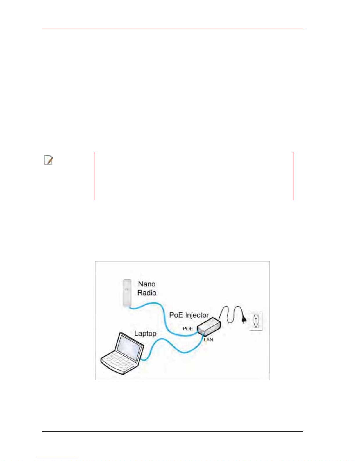
4. Point-to-Point Backhaul
Preparation
•3-AP.cfg •9-AP.cfg •15-AP.cfg
•3-S.cfg •9-S.cfg •15-S.cfg
• 4-A P.cfg • 10-AP. cf g • 16-AP.cfg
•4-S.cfg •10-S.cfg •16-S.cfg
• 5-A P.cfg • 11-A P. cf g • 1 7-AP. cfg
•5-S.cfg •11-S.cfg •17-S.cfg
• 6-A P.cfg • 12-AP. cf g • 18-AP.cfg
•6-S.cfg •12-S.cfg •18-S.cfg
NOTE
When using a radio link (pendant) to the recording truck, the following
configuration files are also required:
• Recorder-AP.cfg
•Recorder-S.cfg
See “Connecting to the Recording Truck” on page 92 for more information on
using a pendant radio link.
2 Configure the computer to be a private network with a static IP address of
192.168.1.100. See the Troubleshooting Guide, Additional Information chapter, Setting a
Static IP Address section if you need instructions on setting the IP address.
3 Connect a single radio to the computer.
Figure 4–7 Ubiquiti NanoStation Private Network Connection
72 RT System 2 v2.3 Deployment Guide R01.i
© 2010-2014 Wireless Seismic, Inc. All rights reserved.
Page 73

4. Point-to-Point Backhaul
Preparation
4 Open the Ubiquiti Discovery Tool by double-clicking the shortcut on the desktop.
Figure 4–8 Ubiquiti
Discovery Tool Icon
NOTE
TIP
NOTE
Ensure that the .bat file and the .jar file are in the same directory.
The discovery tool can also be downloaded from the following location:
http://www.ubnt.com/download#app
Extract the files from the downloaded ZIP file to the desktop.
5 The Discovery window opens and displays a list of all Discovered Devices:
The factory default IP address for the radios is 192.168.1.20. Configure the
radios one at a time.
R01.i RT System 2 v2.3 Deployment Guide 73
© 2010-2014 Wireless Seismic, Inc. All rights reserved.
Page 74
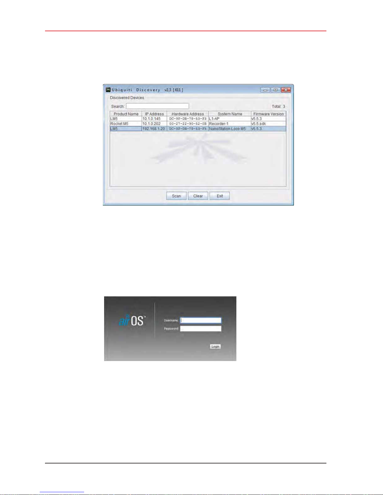
4. Point-to-Point Backhaul
Preparation
Figure 4–9 Ubiquiti Discovery Window
6 If the list does not look correct, click Scan.
7 Right-click one of the radios and then click Web UI. For example, right-click the
following row:
L M5 | 192.168.1.20 | DC-9F-DB-78-53-F3 | NanoStation Loco M5
and then click Web UI. The airOS login window opens:
Figure 4–10 Ubiquiti airOS Login Window
8 Type the following credentials and click Login:
Ɣ Username: ubnt
Ɣ Password: ubnt
9 The radio configuration window opens. Click the System tab.
74 RT System 2 v2.3 Deployment Guide R01.i
© 2010-2014 Wireless Seismic, Inc. All rights reserved.
Page 75
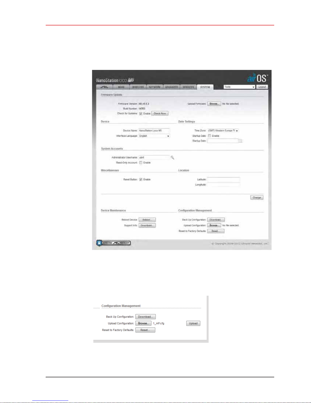
4. Point-to-Point Backhaul
Preparation
10 In the Configuration Management
Browse to the configuration file (for example
Figure 4–12 Ubiquiti, Upload Configuration File
R01.i RT System 2 v2.3 Deployment Guide 75
Figure 4–11 Ubiquiti airOS Window, System Tab
ĺ Upload Configuration area, click Browse.
1-AP.cfg), and then click Upload.
© 2010-2014 Wireless Seismic, Inc. All rights reserved.
Page 76
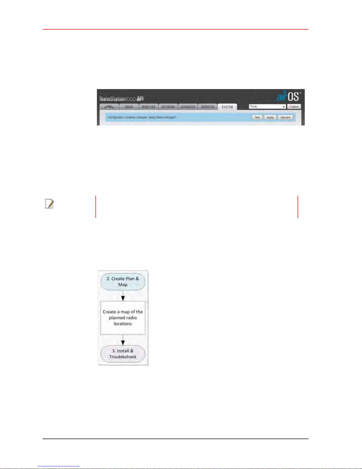
4. Point-to-Point Backhaul
Create Plan and Map
11 Click Apply.
12 The radio reboots and obtains a new IP address if a DHCP server is active. The current
session of airOS is no longer valid since the IP address of the radio has changed.
13 Close the browser window.
14 Disconnect the radio. It is now ready for deployment.
15 Continue connecting radios and uploading configuration files until they are all configured.
Figure 4–13 Ubiquiti, Apply Configuration Changes
NOTE
Radios were labeled prior to shipment and there should be a 1:1 correlation
between radios and configuration files. Make sure the correct configuration file is
loaded onto the corresponding radio.
4.3 Create Plan and Map
Using the documents provided for the job (survey, planned LIU locations, and so on), create
a plan to plot radio locations and map the layout of AP and S radios.
Figure 4–14 Create Plan and
Map Troubleshooting Flow
Keep the following in mind as you create the layout plan:
i Point the radio pairs directly at each other whenever possible maintaining line-of-sight
around obstructions (see “Maintain Line-of-Sight” on page 77).
76 RT System 2 v2.3 Deployment Guide R01.i
© 2010-2014 Wireless Seismic, Inc. All rights reserved.
Page 77
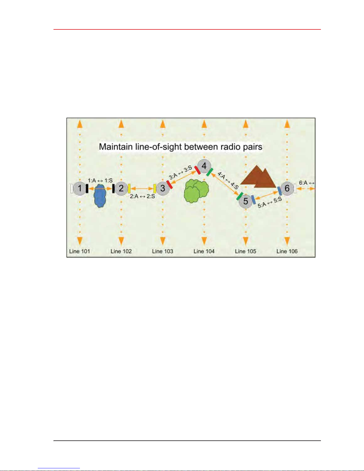
4. Point-to-Point Backhaul
Install and Troubleshoot
i Use a tool such as Google Earth or Global Mapper to create an Elevation Profile to assist
with determining the best locations for radio towers. See “Creating a Google Earth
Elevation Profile” on page 113 for an example.
i An Access Point communicates only with a Station. An Access Point cannot communicate
with an Access Point, and a Station cannot communicate with a Station.
Figure 4–15 Maintain Line-of-Sight
4.4 Install and Troubleshoot
This section describes how to install the radios and troubleshoot the radio communications.
R01.i RT System 2 v2.3 Deployment Guide 77
© 2010-2014 Wireless Seismic, Inc. All rights reserved.
Page 78
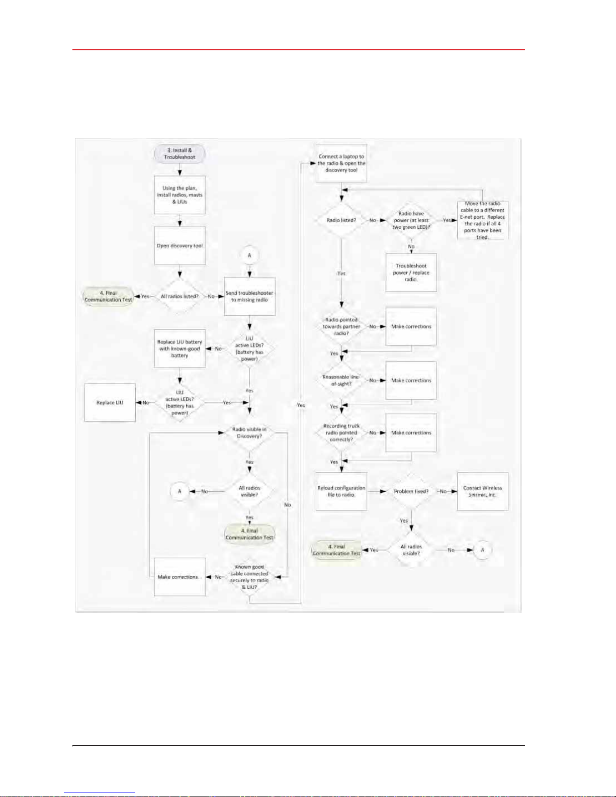
4. Point-to-Point Backhaul
Install and Troubleshoot
Figure 4–16 Install and Troubleshoot the Radios Flow
To install and troubleshoot the radios:
1 Using the plan created in section “Create Plan and Map” on page 76. install all of the
radios, masts, and LIUs. Keep the following in mind as you proceed through the
installation:
78 RT System 2 v2.3 Deployment Guide R01.i
© 2010-2014 Wireless Seismic, Inc. All rights reserved.
Page 79

4. Point-to-Point Backhaul
Install and Troubleshoot
Ɣ Use labels to ensure that the correct radios are in the correct positions.
Ɣ Install the Access Point (A) radios are at the top of the pole, and the Station (S)
radios on the same pole are at least three feet below the Access Point radios as
shown in “Radio-to-Radio Communication” on page 68.
Ɣ Point radio pairs directly at each other where possible (see “Maintain Line-of-Sight”
on page 77). Some inaccuracy is tolerable; however, align the radios as close as
possible using binoculars or compass bearing.
2 From the recording truck, open the Ubiquiti Discovery Tool. Verify that all of the radios
are listed, and verify that each of the radios has a valid IP Address. Note the following:
Ɣ If a radio is listed, that means there is an Ethernet path to the radio.
Ɣ If a radio has a valid IP address that means the DHCP is active, DHCP is being
accepted by the radios, and DHCP is being passed from radio link to radio link.
Ź DHCP server-assigned IP addresses are 10.xxx.xxx.xxx
Ź Non-DHCP server-assigned IP addresses are 192.168.1.xxx
3 If a radio is not listed, send a troubleshooter to the first radio that is not listed (the radio
closest to the recording truck) and perform the following steps:
a Verify that the LIU has active LED lights (the battery has power).
b Verify that the radio is visible in Discovery.
c Verify that the radio is securely connected to the LIU with a known-good cable.
d Connect a laptop to the LIU.
IMPORTANT: The Ethernet ports on the LIU are PoE enabled. When connecting a
laptop computer to the LIU, use a non-powered cable (60-0039) to protect the
computer’s Ethernet port. Do not use a powered Ethernet cable (60-0054). See
“Ethernet Cable Connections Comparison” on page 80 for more information.
e Open the discovery tool and verify that the radio is listed. If the radio is not listed,
perform the following steps.
1) Verify that the radio has power by visually inspecting the LEDs.
2) If the radio has power but is not visible to the laptop, try a different Ethernet
port.
3) If the radio does not have power, troubleshoot the power and/or replace the
radio.
f Verify that the radio is pointed in the direction of its partner (pair) radio and has
reasonable line-of-sight to its partner (pair) (see “Maintain Line-of-Sight” on page
77).
g Verify that the last radio visible from the doghouse is pointed in the correct direction.
h Reload the configuration file to the radio.
i If the above steps fail, contact Wireless Seismic, Inc. for assistance.
R01.i RT System 2 v2.3 Deployment Guide 79
© 2010-2014 Wireless Seismic, Inc. All rights reserved.
Page 80

4. Point-to-Point Backhaul
Final Communication Test
The following table compares the powered Ethernet cable and the non-powered Ethernet
cable:
Table 4–2 Ethernet Cable Connections Comparison
60-0039 LIU to Computer
Signal Name
14-Pin Connector RJ-45 Connector RJ-45 Connector 11-Pin Connector
60-0054 LIU to Radio PoE
B1TX+1B
A2TX-2A
C3RX+3C
NC 4 POSITIVE 4 H
NC 5 POSITIVE 5 F
D6RX-6D
NC 7 RETURN 7 E
NC 8 RETURN 8 L
P — SHIELD DRAIN — P
———NCR*
———NCM*
— *Jumper pins R and M together.
4.5 Final Communication Test
This section describes how to run the final speed test to verify good communication
throughout the backhaul.
80 RT System 2 v2.3 Deployment Guide R01.i
© 2010-2014 Wireless Seismic, Inc. All rights reserved.
Page 81
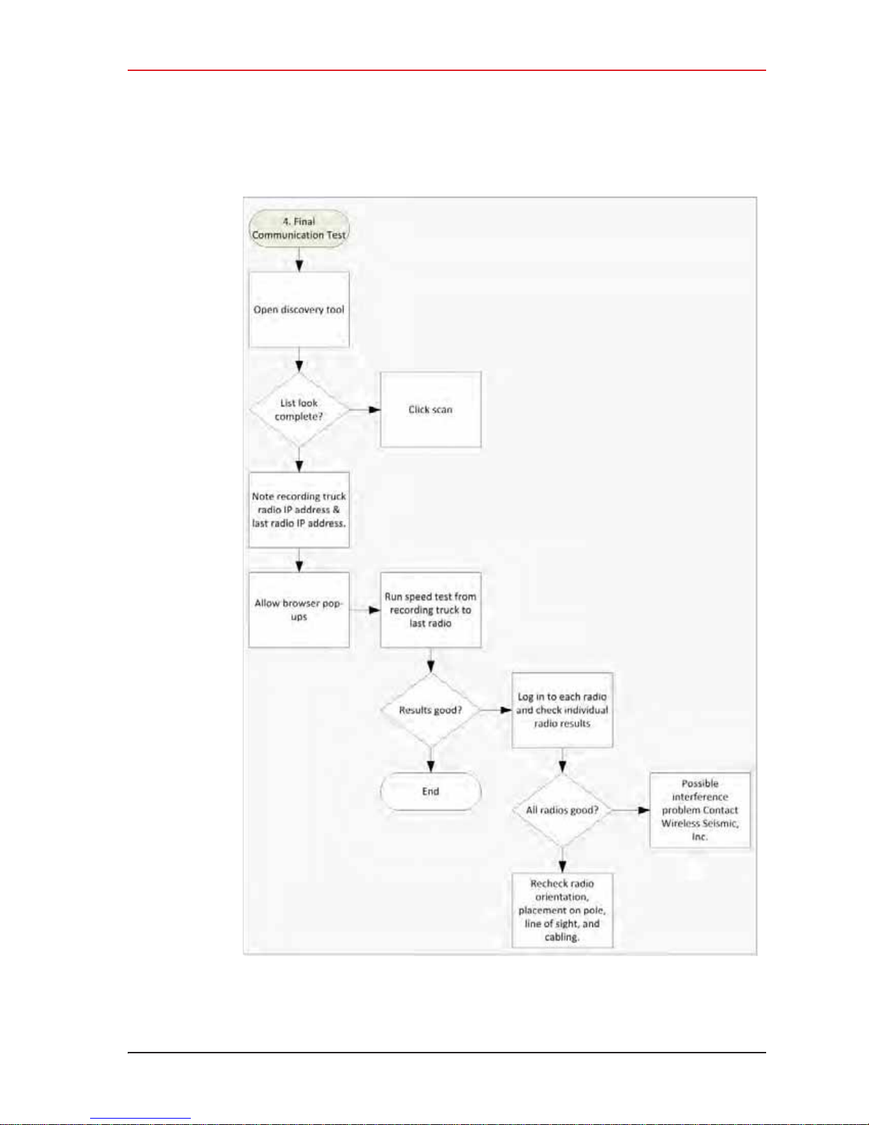
4. Point-to-Point Backhaul
Final Communication Test
R01.i RT System 2 v2.3 Deployment Guide 81
Figure 4–17 Final Communication Test Flow
© 2010-2014 Wireless Seismic, Inc. All rights reserved.
Page 82

4. Point-to-Point Backhaul
Final Communication Test
To run the speed test:
1 Verify that all radios are listed in the Ubiquiti Discovery Tool as described in step 4 on
page 73 through step 6 on page 74.
2 Make a note of the following IP addresses:
Ɣ The last radio in the line segment, that is, the radio farthest away from the recording
truck:
______.______.______.______
Ɣ The radio at the recording truck:
______.______.______.______
3 The speed test should be run from the recording truck radio to the radio farthest from
the recording truck. Log in to the recording truck radio as described in step 4 on page 73
through step 8 on page 74.
4 Verify that browser pop-ups are allowed:
Ź Firefox – Tools ĺ Options ĺ Content ĺ clear the Block pop-up
Ź Internet Explorer – Tools ĺ Internet Options ĺ Privacy ĺ clear the
Ź Chrome – Settings button ĺ Settings ĺ Show Advanced Settings ĺ
5 Click Tools
windows check box
Turn on Pop-up Blocker check box
Privacy area
show pop-ups
ĺ click OK
ĺ Content Settings ĺ Pop-ups area ĺ Allow all sites to
ĺ click Done
ĺ Speed Test.
ĺ click OK
Figure 4–18 Ubiquiti airOS Tools
6 In the Speed Test window, perform the following steps:
a Click the IP address for the radio farthest from the recording truck in the Select
Destination IP list:
82 RT System 2 v2.3 Deployment Guide R01.i
© 2010-2014 Wireless Seismic, Inc. All rights reserved.
Page 83
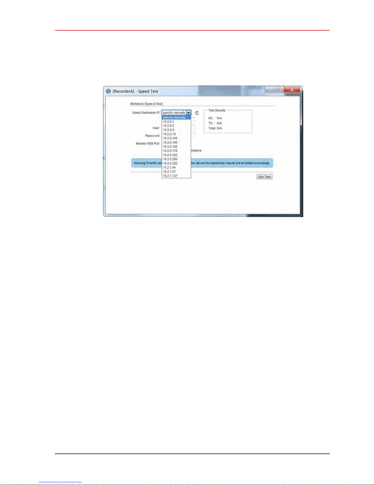
4. Point-to-Point Backhaul
Final Communication Test
Figure 4–19 Speed Test Window
b Type ubnt in the User text box.
c Type ubnt in the Password text box.
d Type 443 in the Remote WEB Port text box.
e The default test Direction is duplex; the test is performed for both transmit and
receive. If you want to run the test in only one direction, perform the following steps:
1) Select the Show Advanced Options check box.
2) Select transmit or receive.
f Click Run Test.
g Good Test Results are as follows:
Ź RX (receive) only = 70+ Mbps
Ź TX (transmit) only = 70+ Mbps
Ź Total (duplex) = 90+ Mbps
– RX = 40+ Mbps
– TX = 40+ Mbps
7 If Speed Test re sults are low, use a systematic approach of testing links to identify the
offending radio pairs:
a Log in to a Station (S) radio.
b Click the Main tab and verify the following values:
Ź Signal Strength < -75 dBm
Ź Either the Vertical or Horizontal (Main Tab, Stations only) < -80 (between -65
and -75 is ideal)
Ź Transmit CCQ < 90% (100% is ideal)
Ź Click AP Information in the Monitor area. Verify that the Access Point Signal
Strength < -75 dBm
R01.i RT System 2 v2.3 Deployment Guide 83
© 2010-2014 Wireless Seismic, Inc. All rights reserved.
Page 84
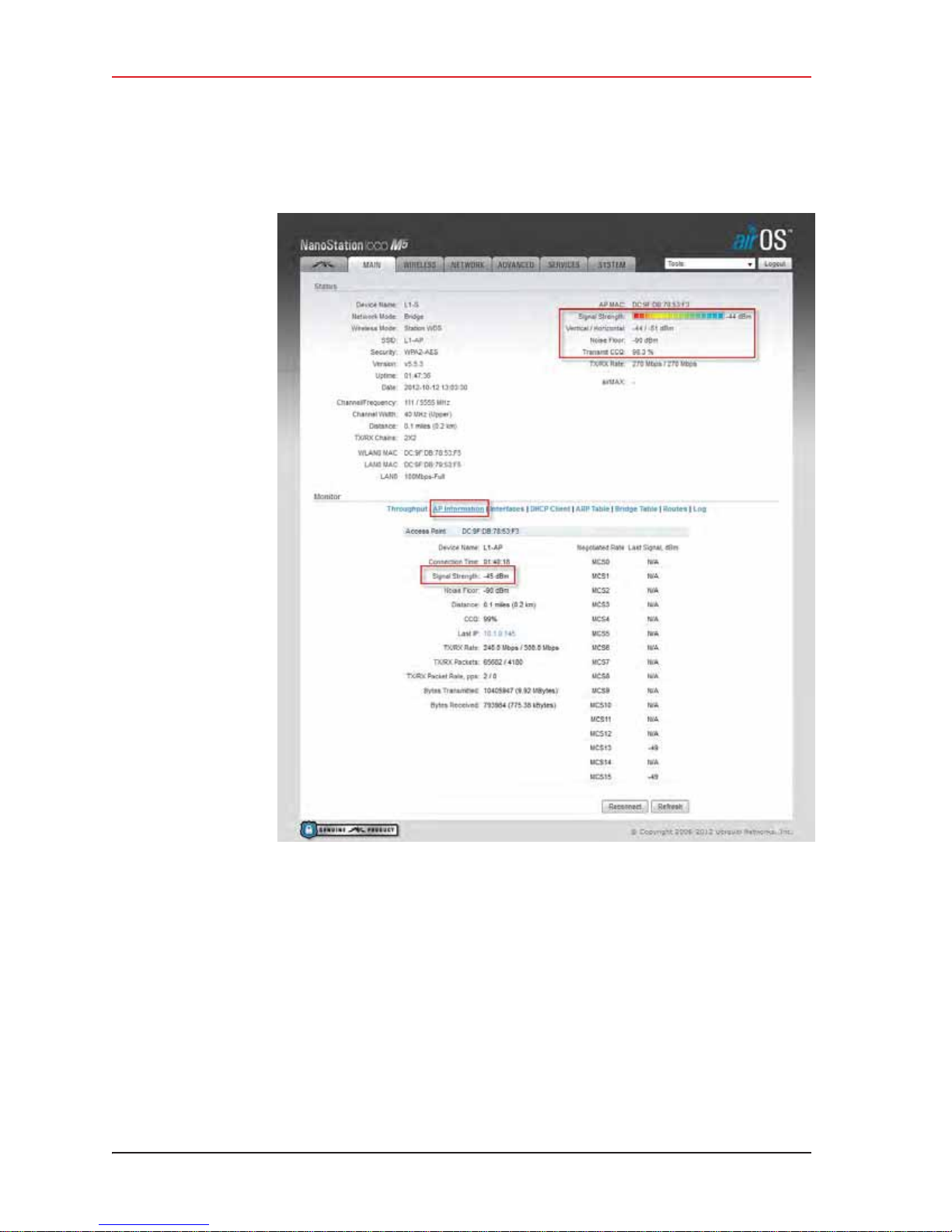
4. Point-to-Point Backhaul
Final Communication Test
c Repeat step a on page 83 and step b on page 83 for all of the radios.
8 If the individual links are all good but the backhaul as a whole does not deliver the
appropriate throughput, it indicates that there is an interference problem.
Contact Andy Prokop, Jerry Stair, or Mike Shilts for project-specific recommendations.
9 If there are individual links with low numbers, perform the following steps to fix them:
a Verify that the radios are pointing in the correct directions.
b Verify that shielding is properly installed. The following figure shows the NanoStation
radio shielding and surge suppressor assembly (56-0032):
84 RT System 2 v2.3 Deployment Guide R01.i
© 2010-2014 Wireless Seismic, Inc. All rights reserved.
Figure 4–20 NanoStation Main Tab
Page 85
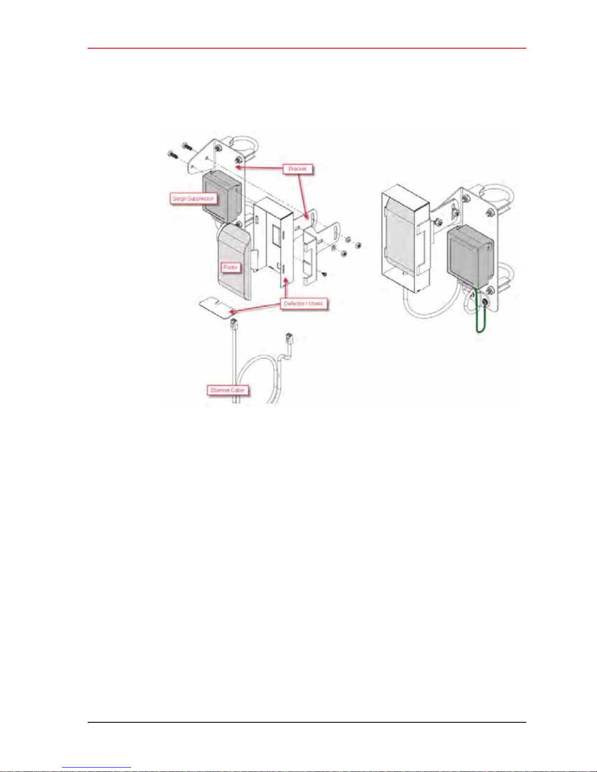
4. Point-to-Point Backhaul
Final Communication Test
Figure 4–21 NanoStation Radio Shielding and Surge Suppressor
c Check for misaligned or improperly installed shielding.
d Verify that the radios on the same pole are at least three feet apart.
e Verify that the Access Point (A) radio is three feet higher on the pole than the Station
(S) radio.
f If possible, raise the poles (masts) to provide the least-obstructed view to the
partner radio as is reasonable.
g Verify that there are no frayed cables or cables with water intrusion.
R01.i RT System 2 v2.3 Deployment Guide 85
© 2010-2014 Wireless Seismic, Inc. All rights reserved.
Page 86

4. Point-to-Point Backhaul
Rolling the Backhaul
4.6 Rolling the Backhaul
As production rolls away from the lines, radios, and towers farthest from the recording truck,
these lines, radios, and towers become available to be used on the other side of the
recording truck.
As you move the equipment, note the following:
i Maintain the A-to-S configuration throughout the survey.
i The poles must stay in sequential order as you roll the spread.
NOTE
The recording truck radio can be any one of the poles; in an ideal case the
recording truck starts at pole farthest from the rec ording truck, for example Pole
18. When you roll Pole 18, you will also need to move the recording truck.
The following figure shows the movement of the poles and recording truck:
86 RT System 2 v2.3 Deployment Guide R01.i
© 2010-2014 Wireless Seismic, Inc. All rights reserved.
Page 87
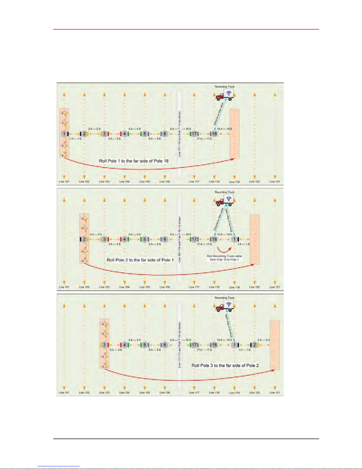
4. Point-to-Point Backhaul
Rolling the Backhaul
Figure 4–22 Rolling the Poles Example for 18 Total Poles
R01.i RT System 2 v2.3 Deployment Guide 87
© 2010-2014 Wireless Seismic, Inc. All rights reserved.
Page 88

4. Point-to-Point Backhaul
Rolling the Backhaul
The following figure shows the movement of the poles when using 18 total poles:
Figure 4–23 Rolling Scheme, 18 Total Poles Example
88 RT System 2 v2.3 Deployment Guide R01.i
© 2010-2014 Wireless Seismic, Inc. All rights reserved.
Page 89
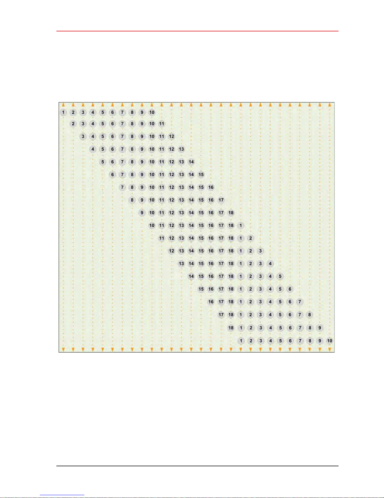
4. Point-to-Point Backhaul
Rolling the Backhaul
For a backhaul using 18 poles, even if you do not have all 18 lines set up at the same time,
the rolling scheme must be followed using all 18 poles as shown in the following figure:
Figure 4–24 Rolling Scheme, 18 Pole Backhaul, 10 Poles in Use
R01.i RT System 2 v2.3 Deployment Guide 89
© 2010-2014 Wireless Seismic, Inc. All rights reserved.
Page 90

4. Point-to-Point Backhaul
Replacing a Radio
4.7 Replacing a Radio
Any number of environmental hazards could destroy an existing radio. When this happens,
replace it using the following instructions:
1 Identify the radio that needs to be replaced.
2 When the radio was initially configured for the point-to-point backhaul, a label was
attached to the radio indicating which configuration file was used. Make a note of the
configuration label (for example, 12:A-P12).
3 Duplicate the configuration label and attach it to the replacement radio using the same
information and color.
The following example label indicates a radio configured for the following:
Ɣ Radio pair 12
Ɣ Access Point
Ɣ Pole 12
12:A-P12 White
4 Locate the corresponding configuration file (for example, 12-AP.cfg) and upload it to the
replacement radio according to step 4 on page 73 through step 13 on page 76.
5 Mark the faulty radio is so that it does not work its way back into the spread.
6 Replace the radio on the pole.
4.8 Upload New Firmware
This section describes how to upload new firmware into the radio.
To upload new firmware:
ĺ Windows computer ĺ Radio Configuration, System tab
1 Click Browse next to Upload Firmware and navigate to the supplied BIN file.
2 Select the file and click Open.
3 Click Upload.
4 Click Update.
5 Do not power off the radio until the firmware is updated.
90 RT System 2 v2.3 Deployment Guide R01.i
© 2010-2014 Wireless Seismic, Inc. All rights reserved.
Page 91
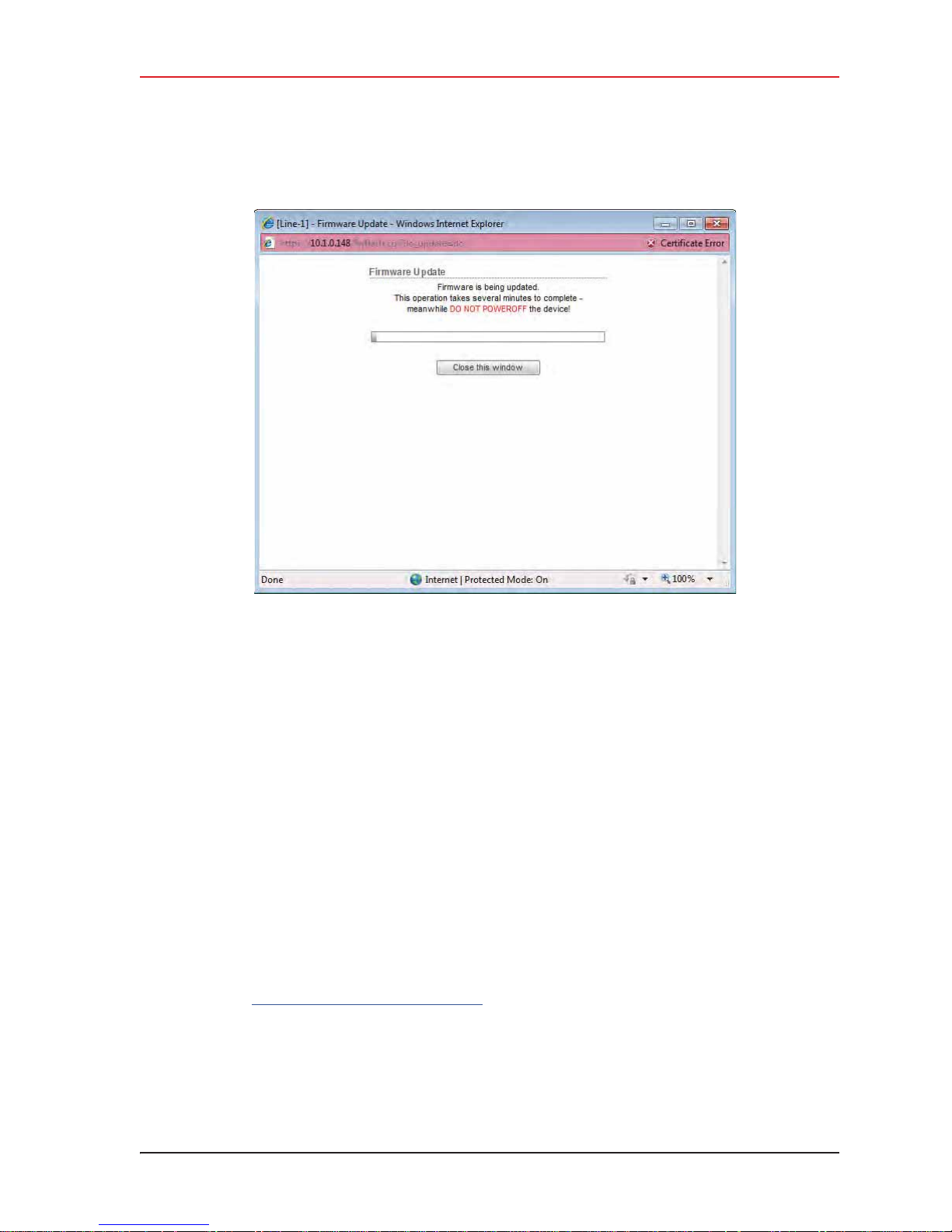
4. Point-to-Point Backhaul
Unzipping the Configuration Files
Figure 4–25 Radio Configuration, Updating Firmware
4.9 Unzipping the Configuration Files
The configuration files are delivered combined into one compressed file (config.zip).
To extract the files, use the built-in Windows 7 extraction process, or you can use a third-
party tool such as 7-Zip.
To use the Windows 7 process:
1 Locate the ZIP file in Windows Explorer.
2 Right-click the ZIP file name and then click Extract All.
3 Browse to and select a folder.
4 Click Extract.
To use 7-Zip:
1 Download and install 7-Zip if it is not already installed:
http://www.7-zip.org/download.html
2 Locate the ZIP file in Windows Explorer.
3 Right-click the ZIP file name and then click 7-zip
4 Browse to and select a folder.
ĺ Extract Files.
R01.i RT System 2 v2.3 Deployment Guide 91
© 2010-2014 Wireless Seismic, Inc. All rights reserved.
Page 92
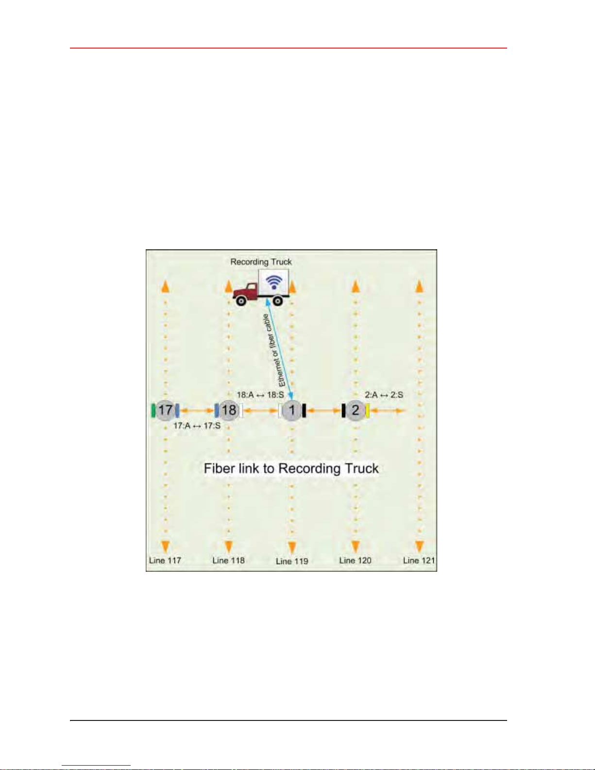
4. Point-to-Point Backhaul
Connecting to the Recording Truck
5 Click OK.
4.10 Connecting to the Recording Truck
The line communicates to the recording truck through an LIU using one of the following
methods:
i Fiber cable
i Radio link (pendant)
The following figure shows a fiber cable connection example:
Figure 4–26 Connecting the Recording Truck with Fiber
92 RT System 2 v2.3 Deployment Guide R01.i
© 2010-2014 Wireless Seismic, Inc. All rights reserved.
Page 93
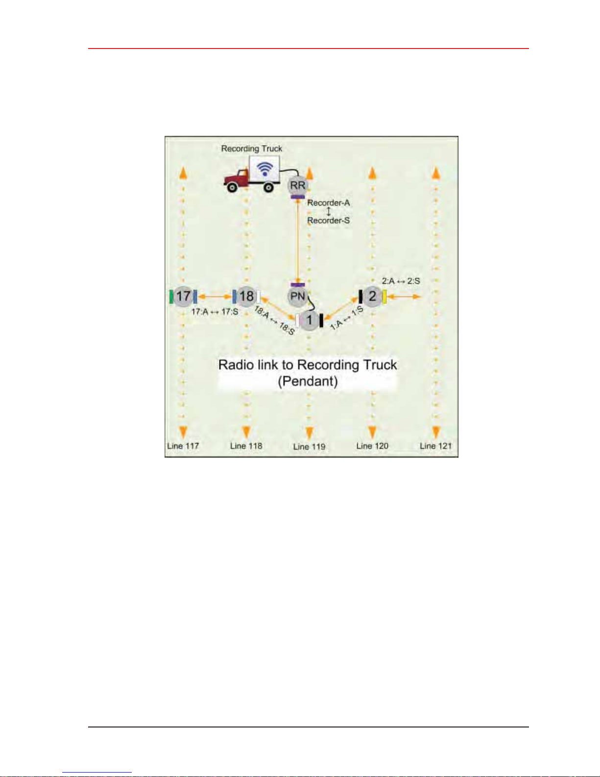
4. Point-to-Point Backhaul
Connecting to the Recording Truck
The following figure shows a radio link (pendant) connection example.
Figure 4–27 Connecting the Recording Truck with a Pendant Radio Link
R01.i RT System 2 v2.3 Deployment Guide 93
© 2010-2014 Wireless Seismic, Inc. All rights reserved.
Page 94
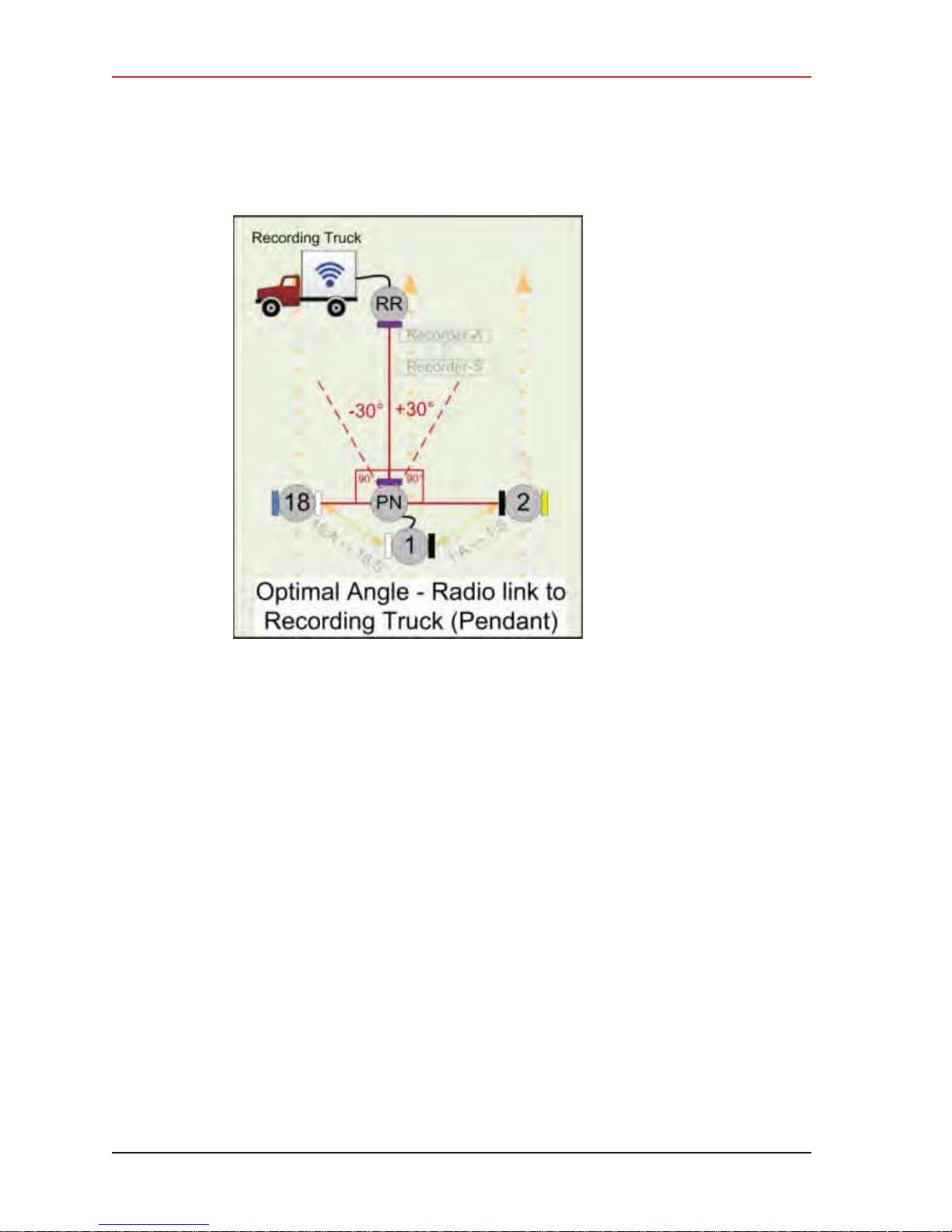
4. Point-to-Point Backhaul
Connecting to the Recording Truck
The following figure shows the optimal angle between the pendent and the line.
Figure 4–28 Optimal Angle, Radio Link to Recording
Truck
94 RT System 2 v2.3 Deployment Guide R01.i
© 2010-2014 Wireless Seismic, Inc. All rights reserved.
Page 95
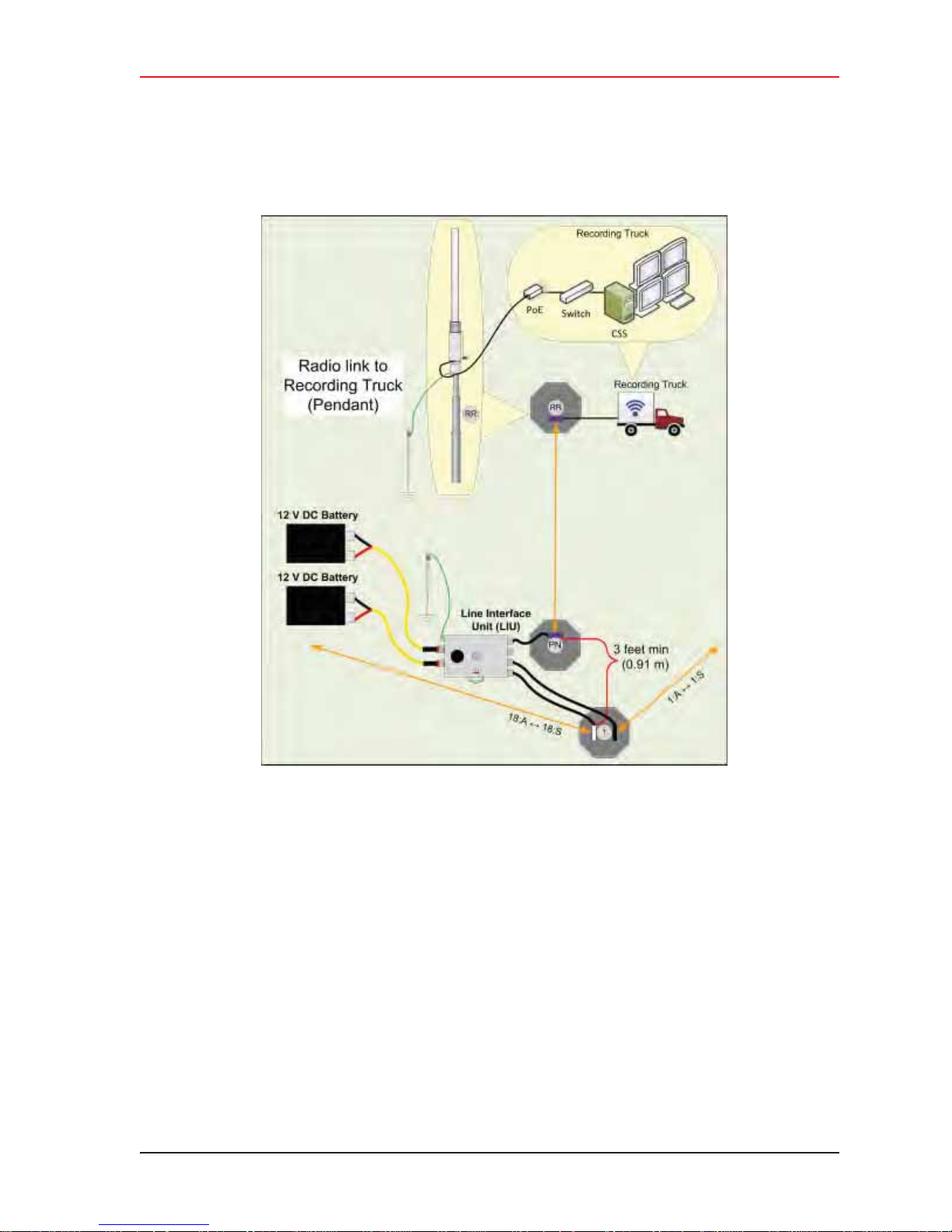
4. Point-to-Point Backhaul
Connecting to the Recording Truck
The following figure shows the connections for the pendant radio link example.
R01.i RT System 2 v2.3 Deployment Guide 95
Figure 4–29 Connecting the Pendant Radio Link
© 2010-2014 Wireless Seismic, Inc. All rights reserved.
Page 96

4. Point-to-Point Backhaul
Connecting to the Recording Truck
The following table lists information about the pendant radio connection.
Item Description
Configuration The following additional configuration files are provided:
Table 4–3 Pendant Radio Link Elements
• • Recorder-AP.cfg
• • Recorder-S.cfg
RR • The radio at the recording truck is a Rocket radio with an Omni
PN • The radio at the line is a NanoStation radio with a built-in
Batteries • Adding a third radio to the LIU i ncreases the battery usage at
antenna and is indicated in the drawings as RR (Recorder/
Rocket).
• Use the Recorder-AP.cfg file with this radio.
• The RR radio should be installed at the top of the pole, pointing
directly at the pendant radio (PN).
antenna and is indicated in the drawings as PN (Pendant/Nano).
• Use the Recorder-S.cfg file with this radio.
• The PN radio should be installed at the top of th e pole, pointing
directly at the recording truck radio antenna (RR).
• The optimal angle between the pendant radio link (RR to PN)
and the next LIU in the line segment (pearl) is 90° as shown in
“Optimal Angle, Radio Link to Recording Truck” on page 94. If
necessary, ±30° off of perpendicular should also work.
• The PN radio should be at least 3 ft (0.91 m) from the line pole
(Pole 1 in the example shown in “Connecting the Recording
Truck with a Pendant Radio Link” on page 93). Use as much
distance as you can as allowed by your cable lengths.
• The PN radio and pole should be between th e line and the
recording truck as shown in “Connecting the Recording Truck
with a Pendant Radio Link” on page 93.
this position. To ensure that the LIU does not reset due to a low
or depleted battery, keep two batteries connected to the LIU at
all times.
• The battery with the lowest voltage is used until the voltage falls
below the Unit Thresholds ? LIU Voltage Warning number
(usually about 11V). At this point, the LIU auto-swaps to the
battery with the higher voltage. Monitor the battery status in
the Ground Equipment Table. Replace the low-voltage battery
with a fully-charged battery as soon as possible after the battery
auto-swap occurs.
96 RT System 2 v2.3 Deployment Guide R01.i
© 2010-2014 Wireless Seismic, Inc. All rights reserved.
Page 97
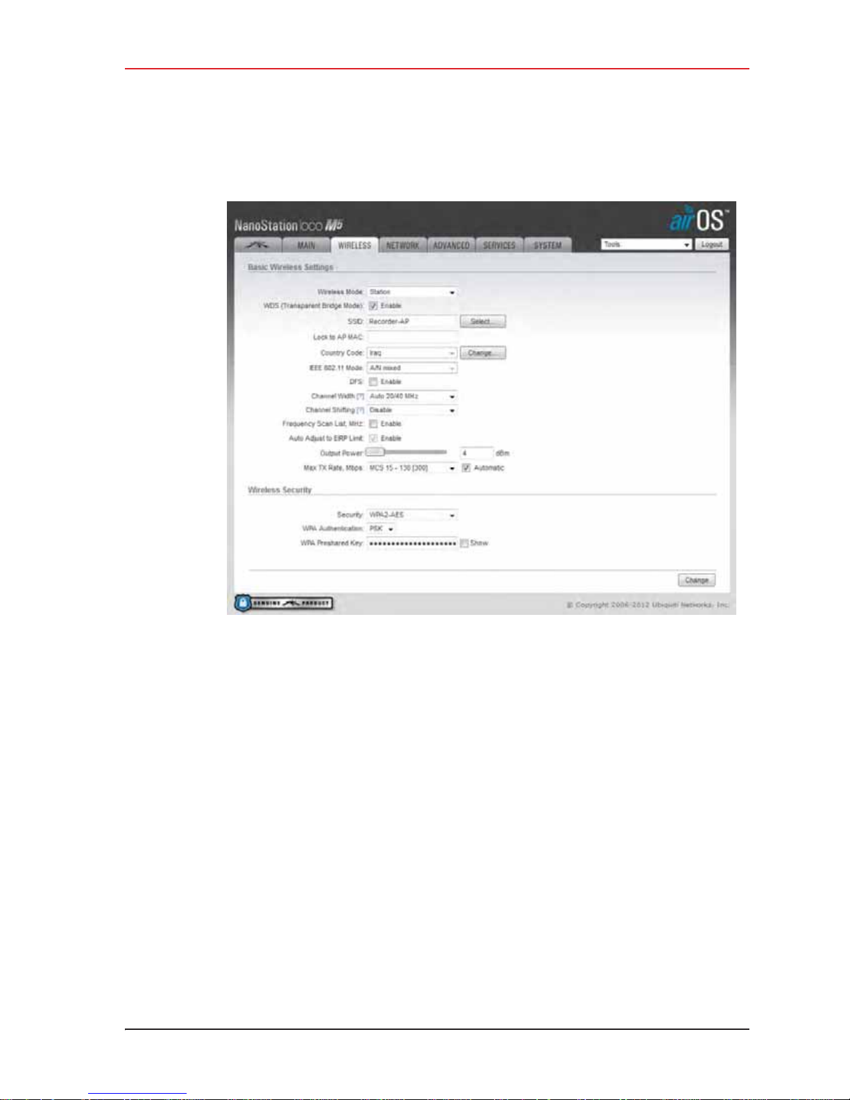
4. Point-to-Point Backhaul
Connecting to the Recording Truck
After the pendant radio link radios are configured and installed, log in to the PN radio and set
the power level to the minimum amount required to achieve communication with the RR.
Figure 4–30 Wireless Tab
To set the PN radio power level:
1 Click the Wireless tab.
2 Move the Output Power slider bar to the desired power level.
3 Click Change at the bottom of the window.
4 Click Apply Command at the top of the window.
5 Wait 30 – 60 seconds.
R01.i RT System 2 v2.3 Deployment Guide 97
© 2010-2014 Wireless Seismic, Inc. All rights reserved.
Page 98
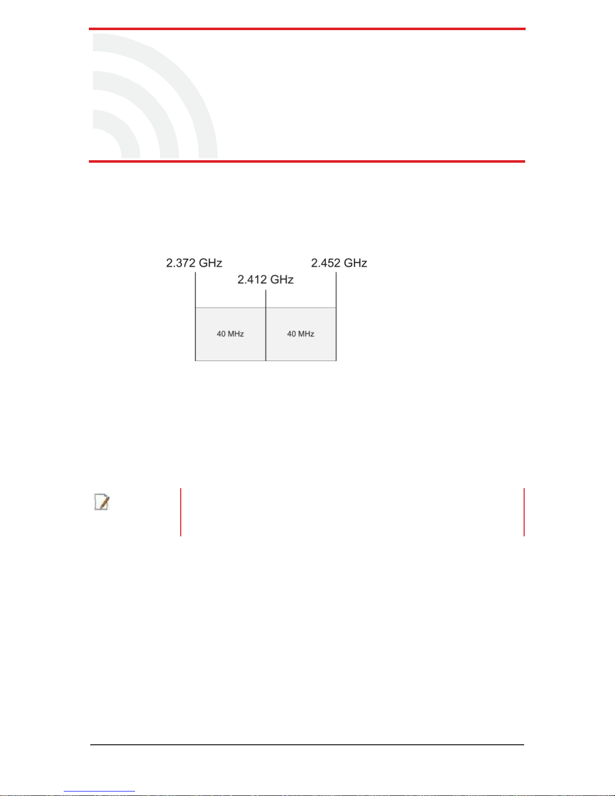
5.1 Overview
A channel is a frequency band of a specified width. For example, if the center frequency
is 2.412 GHz, and the frequency band is 80 MHz wide, there are 40 MHz on either side
of the center frequency, and the frequency range for that channel is 2.372 to 2.452 GHz.
5
5. Point-to-Multipoint Backhaul
NOTE
Figure 5–1 Channel, 80 MHz Wide Frequency
Band
Some custom configurations will require multiple channels operating at the same time.
Verify that channel ranges do not overlap to avoid interference.
The recording truck radios are configured Access Points (A) and the line station radios
are configured as Stations (S).
An Access Point communicates only with a Station. An Access Point cannot communicate
with an Access Point, and a Station cannot communicate with a Station.
A line station mast requires an LIU to communicate with the recording truck. A
mast located at the recording truck can communicate using an LIU or a PoE
connected directly to the recording truck computer. See the following figures for
examples.
RT System 2 v2.3 98 Deployment Guide R01.i
© 2010-2014 Wireless Seismic, Inc. All rights reserved.
Page 99
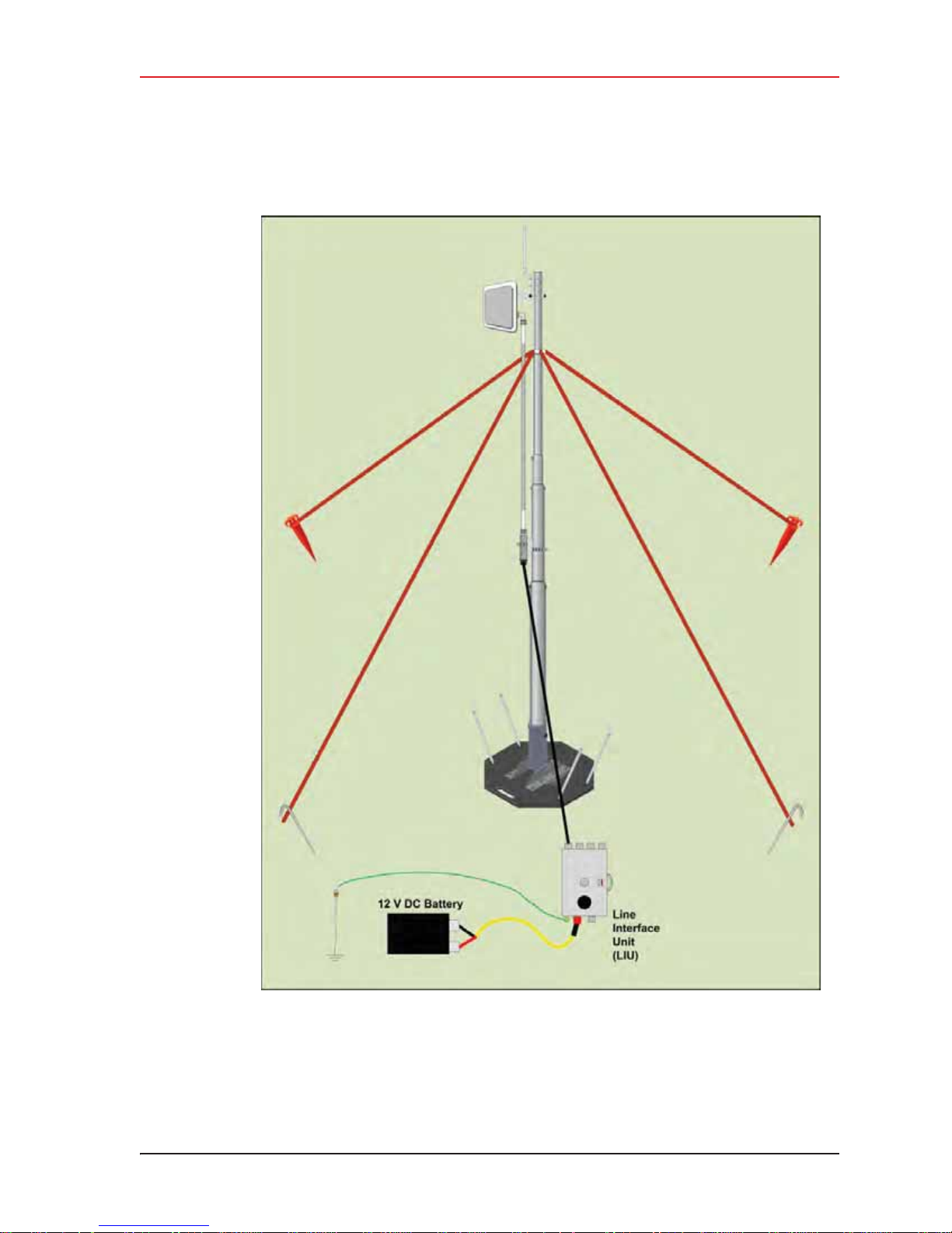
5. Point-to-Multipoint Backhaul
Overview
R01.i RT System 2 v2.3 Deployment Guide 99
Figure 5–2 Line Station Mast (Bullet Radio)
© 2010-2014 Wireless Seismic, Inc. All rights reserved.
Page 100
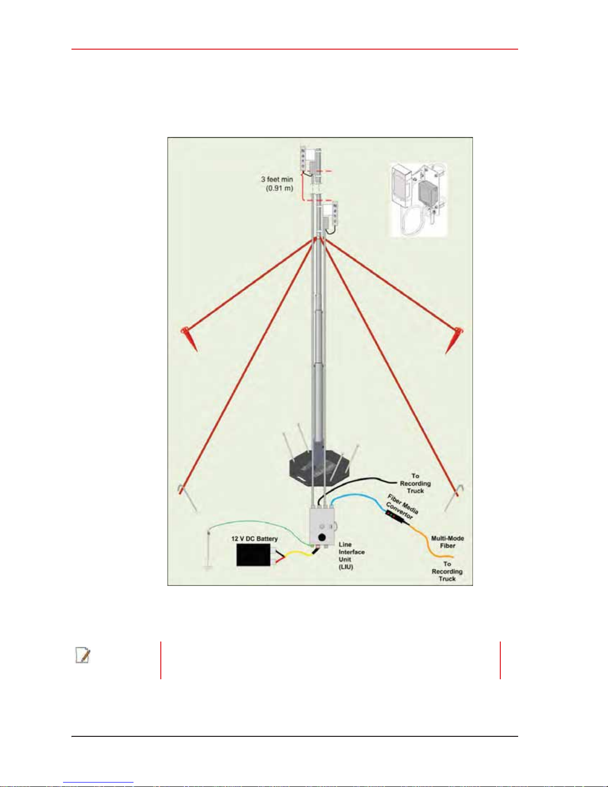
5. Point-to-Multipoint Backhaul
Overview
Figure 5–3 Recording Truck or Line Station Mast (NanoStation Radio)
NOTE
100 RT System 2 v2.3 Deployment Guide R01.i
If using the mast at the recording truck, connect the LIU with an Ethernet or
Fiber cable to the recording truck. If the mast is not used at the recording truck,
the connections shown in the figure to the recording truck are not used.
© 2010-2014 Wireless Seismic, Inc. All rights reserved.
 Loading...