

Page 1
360º VEHICLE SURROUND
VIEW MONITORING SYSTEM
MANUAL BOOK
© 2017 Wireless Prime INC. All Rights Reserved.
Page 2
Contents
Introduction
Product Features
Specifications
Instructions
Installation Instructions
Bus Installation
Truck Installation
Host Device Installation
Remote Control Instructions
Camera Calibration
Calibration for Buses and Trucks
Position Calibration
Merging Calculation
2
3
4
5
5
7
8
9
9
10
10
11
12
Function Settings
Interface Settings
Upgrade and Restore
Other Settings
Video Settings
Video Recording Functions
Smart Power Management
Disclaimers
About Wireless Prime
12
12
12
13
13
13
13
15
16
© 2017 Wireless Prime INC. All Rights Reserved. 1
Page 3

Introduction
This guide is to provide users with an understanding of the system installation
procedure, camera calibration steps, and interaction with the system menu.
The VR3D Player 360º Vehicle Surround View Monitoring System synthesizes images
from four cameras to create a true 3D view of a vehicle's surroundings. The technology
enables flexible omni-directional monitoring around a vehicle from a dynamically
definable perspective or "free eye point." This technology is able to capture a complete
360º view surrounding the vehicle, eliminating blind spots for safe driving and parking.
This system offers various SVM configurations such as -HDMI/LVDS/AV with either 2D
or 3D, as well as integrated four channel car DVR function with 24-hour video loop
recording supported.
Safety Tips
Please read this manual carefully before using.
Serious traffic accidents may be caused by constant viewing of the screen or by
operating the system while driving.
SVM is a parking and driving assistant system which offers full view of the vehicle’s
surrounding, eliminating blind spots and providing a guide for safe driving and parking.
There may be inconsistencies between the image on the screen and the surroundings
of the vehicle. Please use caution when driving with this system.
Never hotplug the host device when power is connected. The host device cannot be
exposed to liquid. Please pay attention to heat dissipation.
Please contact professional installation service providers in case of any abnormal
situations.
© 2017 Wireless Prime INC. All Rights Reserved. 2
Page 4

Product Features
4X 180º ultra-wide fish-eye cameras.
Seamless video merging based on dual core ARM CPU and hardware
high-efficiency acceleration engine.
Choose between Arbitrary and dynamic 3D mode view angle for better view of
surrounding environment.
Independent fish-eye calibration parameter and algorithm for each camera.
Pixel statistic engine for realtime brightness balance across four camera channels.
3D video de-interlacing and noise reduction technology for CVBS signal decoding.
Supports alternative recording media for TF card or USB disk.
Simple calibration with calibration tape and packing box, applicable for almost all
types of vehicles including buses, trucks, lorries, limousines, tanks, and even jumbo
jets. Typical length of the vehicle is 5.5m, 6.5m, 10m & 13m.
Smart power management for conserving vehicle battery.
High video recording resolution up to 1440x960.
OE quality for main chipset with protected circuit and devices to provide the best
system performance and stability.
© 2017 Wireless Prime INC. All Rights Reserved. 3
Page 5

Specifications
TYPE SPECIFICATION
Video
Indicator Lamp
/Blinker
G-sensor
Compression
Video Interface
Input / Output Impedance
Amplitude
Bandwidth
Sampling Frequency
DP(Differential Phase)
DG(Differential Gain)
SNR
High beam
Left/Right Turning Blinker
Reversing Lamp
BM250E
Algorithm
Resolution
Bitrates
Mini plug connector
75Ω
Typical 1Vpp, 1.2Vpp Maximum
8MHz
13.5MHz
<0.8°TYP
<3%TYP
70dB
Optional
Yes
Yes
Bosch
H.264 [email protected]
1440*960@30fps
5Mbps,3Gbyte/Hour
Recording Media
TF CARD
Disk Capacity
Power Consumption
Dimension
Weight
Environments
Voltage Tolerance Working Voltage
USB Disk
4-CH DVR + SVM mode
4-CH DVR mode
Sleep Mode
L*W*H
Normal Working
Storage
Relative Humidity
USB Disk(High Priority)/TF
32G SDIO3.0/SDIO2.0
32G USB2.0
600mA
440mA
<10mA
123*81*25mm(Host Metal box)
220g
-20℃~+85℃
-40℃~+105℃
0~95%
9.5V~36V
© 2017 Wireless Prime INC. All Rights Reserved. 4
Page 6

Instructions
Installation Instructions
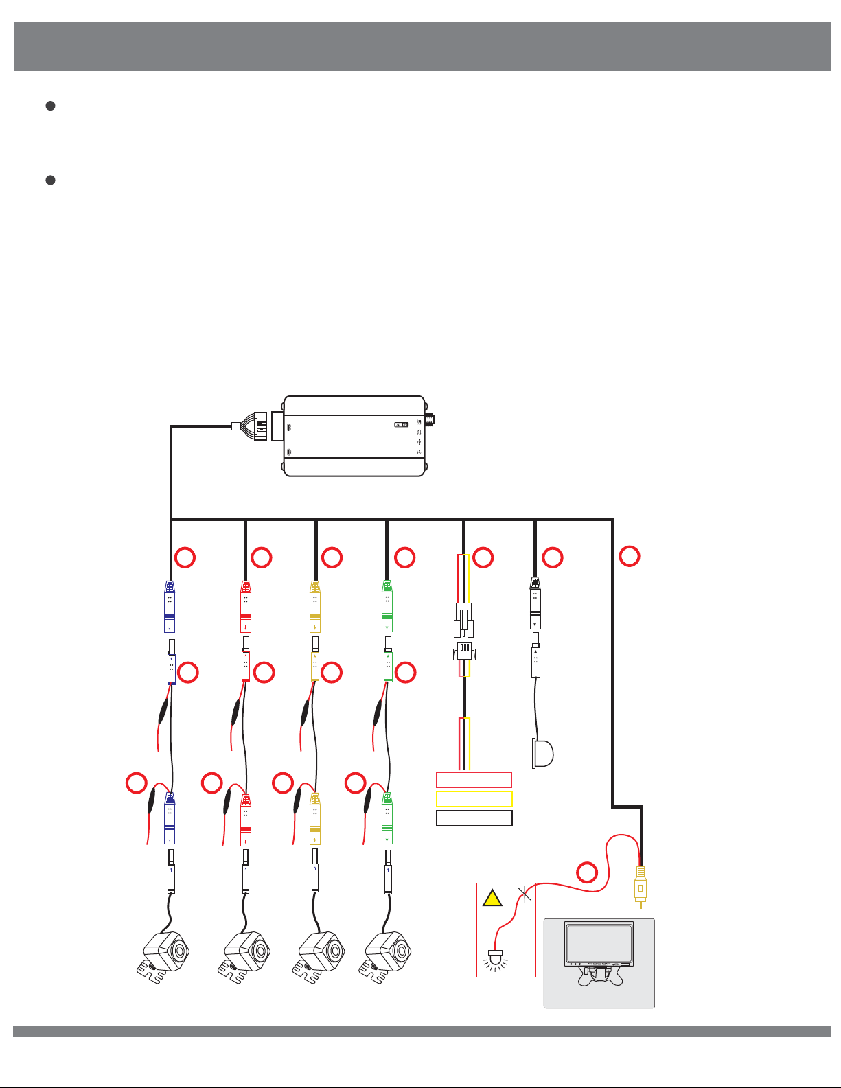
1) Wire Routing Inside the Car
Please refer to wiring diagram for more details.
Please pay close attention to the color and connector size of each extending
cable. Wire routing should be installed from cameras to the host device side. All
the cables should be gathered to the host device side.
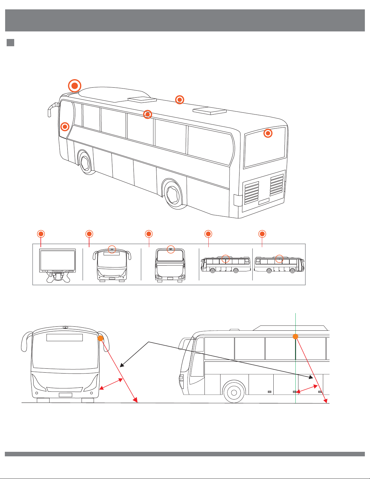
2) Camera Installation
Please refer to the corresponding section for detailed installation steps.
Embedded or out-cell installation for side cameras depends on the size of the
side mirrors as well as the space available for installation, especially for large
vehicles. Proceed with caution when dissasembling the side mirrors or drilling
installation holes to ensure that they do not break.
3) Host Installation
It is strongly recommended that the host be installed inside or behind the tool
cabinet, as this will ensure that the TF card or USB disk is easily accessible.
4) Wiring Test
Double check all of the wire connections before turning on the power. Do not
plug in live connections.
5) Functional Test
Test the main functions and settings of the host device.
6) Side Camera’s Angle Adjustment
Adjust the camera to select the proper angle at which side calibration tape is
overlapping with the reference guide line on the screen.
7) Camera Calibration
Step-by-step camera calibration can be accessed in the system menu. Once the
calibration data is completely collected, the system software will automatically
complete the video merging.
© 2017 Wireless Prime INC. All Rights Reserved. 5
Page 7
Instructions
8) Device Fixing
Fix the wire connections, cameras and host device.
9) Reconversion
Recover all the parts of the vehicle.
NOTE: Please install in cable extension kit in the proper order according
to the vehicle length. Standard extension cable lengths are as listed:
Front Camera: 4M*2
Rear Camera: 6.45M*2
Left Camera: 3.45M*2
Right Camera: 3.45M*2
same with
cable 13,
either-or
Camera
extend
13 14
(High Beam)
cable
Host Device
01 02 03 04
05 06 07 08
same with
cable 14,
either-or
same with
cable 15,
either-or
same with
cable 16,
either-or
15 16
(Left Turning)(Reversing) (Right Turning)
09
Power Cable
Pink line ACC
Yellow VBAT+
Black GND
10
IR Receiver
11
AV-OUT
12
!
(Front CAM)
© 2017 Wireless Prime INC. All Rights Reserved. 6
(Back CAM)
(Left CAM) (Right CAM)
DO NOT Connect
Reversing Gear
Signal
DVD Trigger
LCD monitor
Page 8
Instructions
Bus Installation
1
2
5
4
3
1 2 3 4
Front Camera Left Camera Right CameraLCD Monitor Rear Camera
camera angle
0-45º
5
0-45º
© 2017 Wireless Prime INC. All Rights Reserved. 7
Page 9
Instructions
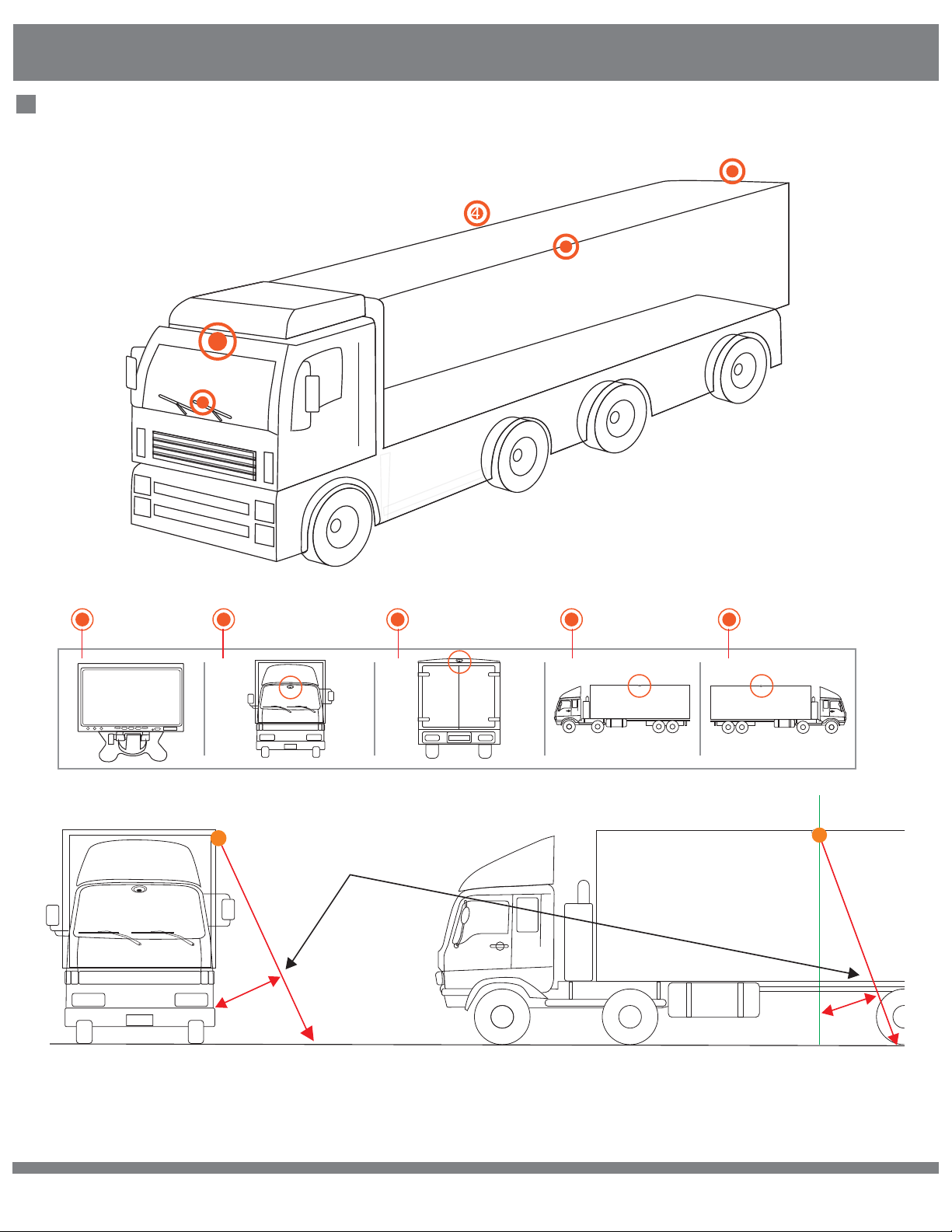
Truck Installation
3
4
5
2
1
1
2 3 4 5
Front Camera Left Camera Right CameraLCD Monitor Rear Camera
camera angle
0-45º
0-45º
© 2017 Wireless Prime INC. All Rights Reserved. 8
Page 10
Instructions
Host Device Installation Instructions
1) Disassemble the panel of the central control unit, and connect the reversing
video channel of the LCD monitor or other display screen(AV in).
2) For IR mode, put the infrared receiver in the proper position.
3) Please connect the anode of the left/right turning signal from the fuse box to
the host wire harness, or from the side mirror turning LED indicator to the
camera side of the extending cable.
4) Connect the power cable to battery supply line and connect the wire harness
to the host device.
5) Fix the host device in the tool cabinet or the space behind the central control
panel.
6) Connect all the cables for the function testing and debugging process, and
assemble the panel back to the control unit.
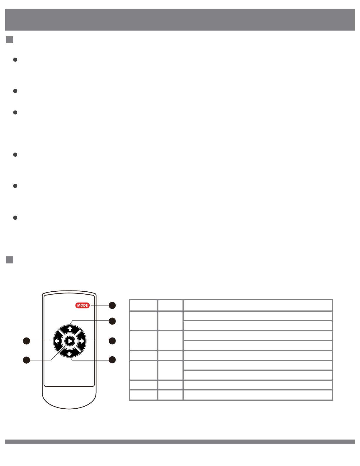
Remote Control Instructions
1
2
5
6
3
4
Key Number Description Function
[1]
[2]
[3]
[4]
[5]
[6]
MODE
UP
RIGHT
DOWN
LEFT
CONFIRM
Enter setting menu.
In 3D mode, press and hold for 2 seconds to enter 4CH recording mode.
While in menu screen, toggle through icons.
In SVM mode, press to toggle between high beam mode and SVM mode.
In SVM mode, press and hold to enter 360 rotatable menu.
In SVM mode, press and hold to enter reversing gear mode.
In menu screen, select next menu option.
In SVM mode, press and hold to enter 360 rotatable mode.
Confirm selected option.
© 2017 Wireless Prime INC. All Rights Reserved. 9
Page 11
Instructions
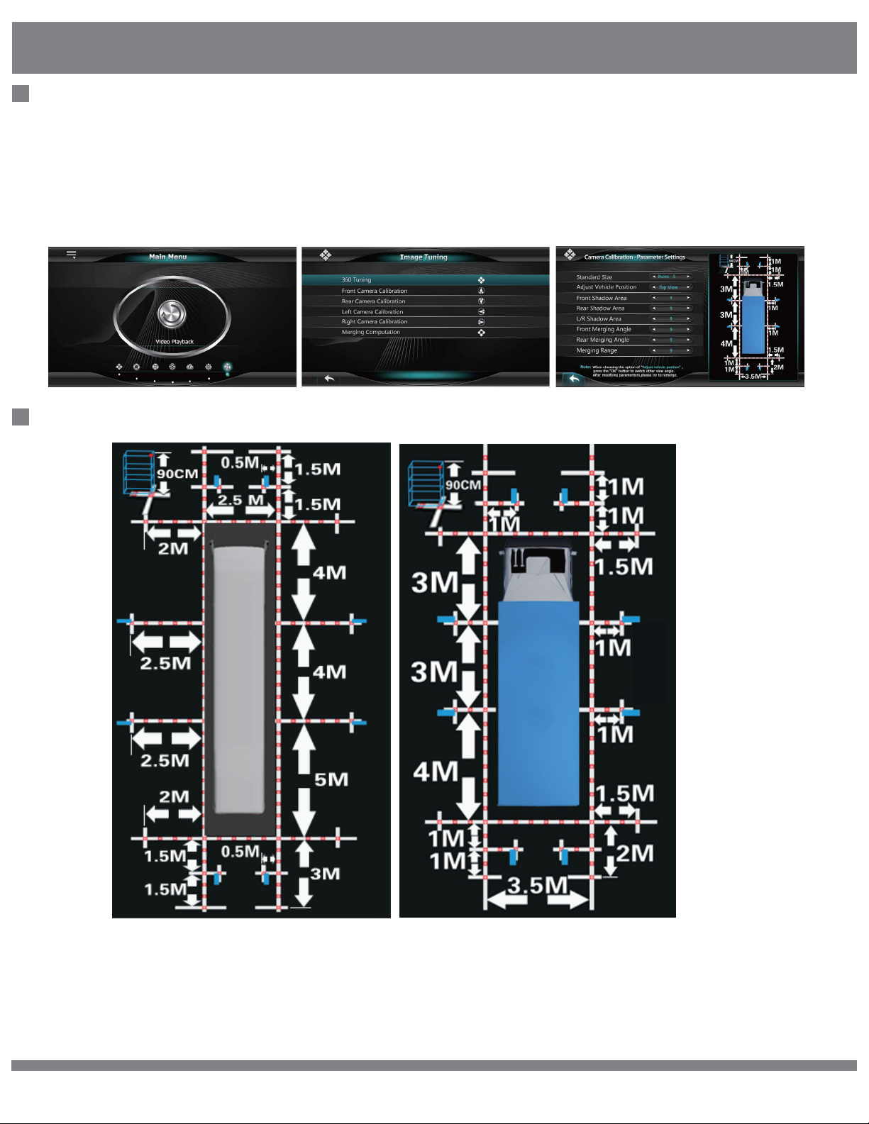
Camera Calibration
Press the "MODE" button on the remote controller to enter system menu
settings. Select the correct calibration size for the applied vehicle model. If you
are not sure about the sensor type, set each step of the shadow setting to 5cm
as default.
Calibration for Buses and Trucks
Past the calibration tape around the vehicle as shown in the diagram. Please refer
to the calibration pictures of different vehicle models and sizes to select the correct
one for your vehicle.
© 2017 Wireless Prime INC. All Rights Reserved. 10
Page 12
Instructions
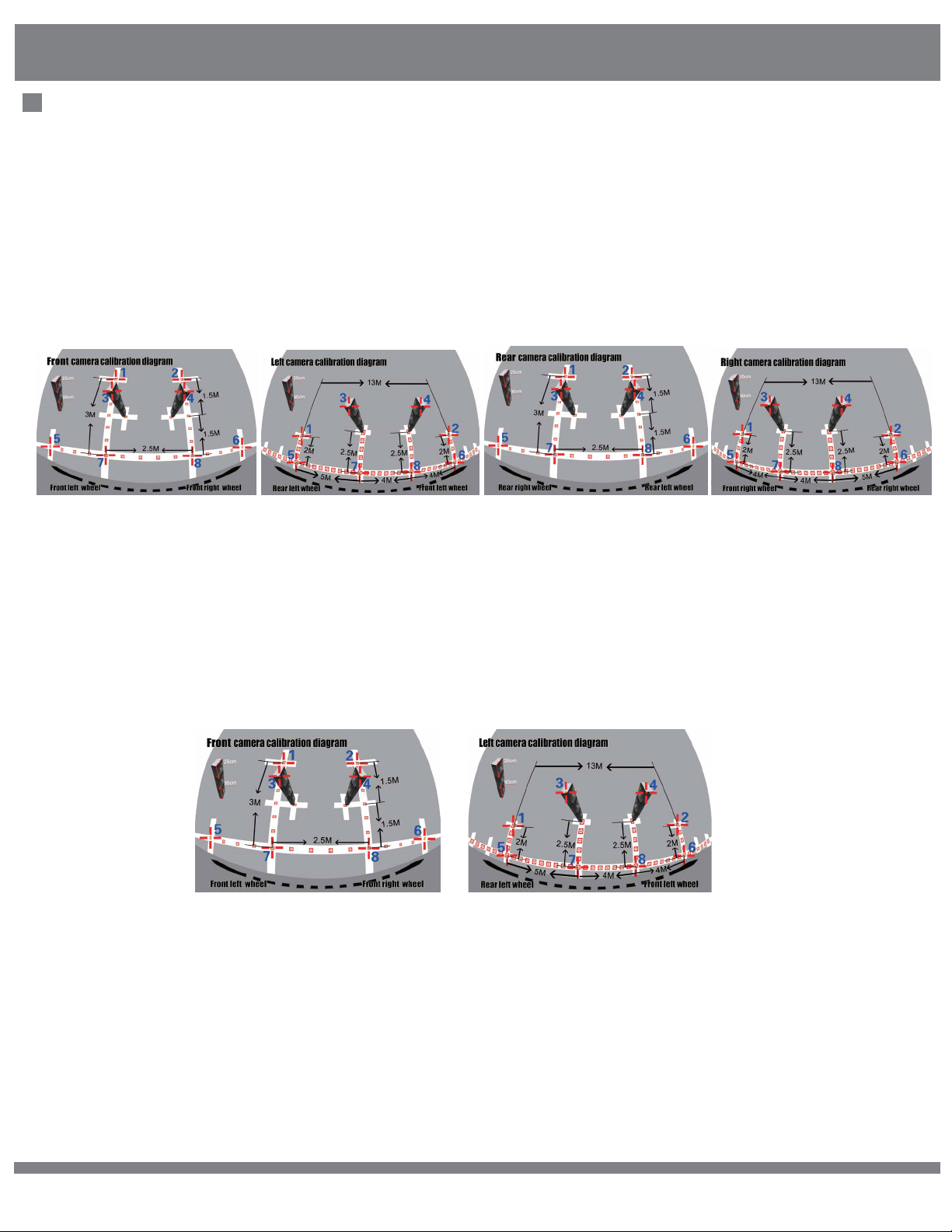
Position Calibration
There are 8 calibration points for each camera which need to be marked in the
screen. The third pixel point and fourth calibration point are always the diagonal
corner of the packing box. The packing boxes can be divided so that each
packing box can be used for calibration 1 camera each time.
NOTE: Put the 3 packing boxes in the correct position as illustrated in the
previous diagram. You may also use other boxes with dimensions of 90cm in
height instead as a calibration reference objects.
Once the cursor starts blinking, you can begin calibrating the four cameras one
at a time. Move the cursor to the corresponding locations by pressing the
directional buttons on the remote control, then press “ok” to mark the current
calibration point on the screen. The system menu will guide you to the next
calibration pixel point in order from 1 to 8, one at a time. Please see the correct
location and sequence of the calibration points as illustrated below:
Press “MODE” to toggle to previous calibration point selection when needed.
NOTE: The locations of the 7th and 8th calibration pixel points are different
between the front and rear cameras and the left and right cameras. The more
accurate calibration points you mark, the better quality the panoramic image
merging will be.
© 2017 Wireless Prime INC. All Rights Reserved. 11
Page 13

Instructions
Merging Calculation
Press “OK” to start image merging.
Do not turn off the system during this operation,
The system will reboot automatically after image merging is finished.
Function Settings
Menu Item List Options Description
Turn Signal
Wake Up
Activate Turn
Signal
Emergency
Blinker Wake Up
High Beam
Function
3D Dynamic
Angle Function
Interface Settings
Menu Item List Options Description
Language Setting
Vehicle Brand
Setting
System Mode
Setting
Adjust the Screen
Y Position
Adjust the Screen
X Position
Turning Signal is optional after engine is turned on. This option is a global
ON/OFF
ON/OFF
ON/OFF
ON/OFF
ON/OFF
English/Simplified Chinese
Vehicle Type 1-3
-9 ~ +9 Pixel
-9 ~ +9 Pixel
switch for left and right turning indicators: when turned on, the system will
respond when a turning event is triggered and vice versa.
When the SVM is in standby mode, this option can control whether
the system can be activated through turning signals.
When the SVM is in standby mode, this option can be used to control whether
the system is activated by Emergency Blinker. You may also use the
Emergency Blinker to set it back to standby mode when this option is set to ON.
The high beam signal can be used to toggle the free-eye point and change the
view angle for surround safety.
Set static or dynamic angle switching when responding to trigger events.
Full Screen
Set the user interface language.
Set the 3D car model.
Set view mode to fullscreen or split screen.
Screen TCON horizontal front and back control.
Screen TCON vertical front and back control.
Reversing Mode
Turning Mode
Driving Mode
Mirrored View
Front Side View
Standard View
Set different view angle when reversing.
Set different view angle when turning.
Set different view angle when driving.
Upgrade and Restore
Menu Item List Options Description
System Restore
Upgrade Options
Version
Information
© 2017 Wireless Prime INC. All Rights Reserved. 12
Default/User Preference
Upgrade 3D Mode
SW.6030.R2.14
Default is not functional at this time. Choose user
preference to restore video settings, window configurations,
etc.
Use this menu to adjust the UI, calibration data, and apps.
Check the hardware/firmware/software version.
Page 14
Instructions
Other Settings
Menu Item List Options Description
Hazard Blinker
Trigger Duration
Display Turn
Delay
Trigger Delay
Reversing/Turning
Trigger Duration
Parking
Surveillance
1min - 5min;
3S - 30S
30S - 5min
30S - 5min
30S - 5min
Disable
The system can be activated through the external Emergency Blinker. When
setting the duration time, ensure you that you first turn ON the Emergency
Blinker Activation Function in the Function Settings Menu.
This option is used to set the delay for the generated reversing indication signal
to inform the monitor that the input video is ready.
This option is used to set the latency to respond to the release event of
the turning signal.
Set the duration for the monitor display after it is turned on by the reversing/
turning signal.
Set surveilance mode for parking.
Video Settings
Enter video settings to adjust the saturation, brightness, contrast, or sharpness
of the image between -9 to +9.
Video Recording Functions
1. Press and hold “MODE” to enter the recording system menu.
2. Press “OK” to stop current recording.
3. Press the up or down directional buttons to navigate between recorded files
per date and timeline.
4. Press “OK” to playback. You may enlarge any of the 4 cameras to full screen
mode by pressing the directional buttons.
Smart Power Management
1) Silent Driving Mode
Silent Driving Mode will continuously record the footage as compressed video on
recording media such as a TF card or USB disk. Note that USB disks have
priority over TF cards.
2) Driving/Parking Assistant Mode
In this mode, maximum power is expected to be consumed as both the recording
board and SVM core board are fully functional. This mode is intended to be used
for short periods of time. Driving Assistant Mode will usually work for several
seconds, and Parking Assistant Mode will usually work for 1-2 minutes.
© 2017 Wireless Prime INC. All Rights Reserved. 13
Page 15

Instructions
3) Standby Mode
In this mode the recording system is in standby. If any vibration is detected by
the G-sensor, the SVM system will trigger the external cameras and LEDs and
immediately begin recording video.
4) Power Off Mode
In this mode the system is turned off except for the Real Time Clock chip and
G-sensor. The system will still be triggered from vibration, except under
circumstances where the battery life is under 11V.
© 2017 Wireless Prime INC. All Rights Reserved. 14
Page 16

Disclaimers
Terms and Conditions
Congratulations on purchasing your new WIRELESSPRIME product. Please read this manual carefully
before using the product. By using this product, you hereby agree to this disclaimer and signify that you
have read it in full. You agree that you are responsible for your own conduct and any content created
while using WIRELESSPRIME products, and for any consequence thereof. You agree to use this product
only for purposes that are proper and in accordance with local regulations, terms and any applicable
polices and guidelines.
By reading this disclaimer, you also agree:
1. Any part of this disclaimer is subject to change without prior notice. Refer to
WWW.WIRELESSPRIME.COM for the latest version.
2. WIRELESSPRIME reserves the right of final interpretation of this disclaimer.
WIRELESSPRIME and the Follow Focus Kit are registered trademarks of Littlecent International
Trading Corp. as names of product, brand, etc., appearing in this manual are trademarks or registered
trademarks of their respective owner companies. This product and manual are copyrighted by
WIRELESSPRIME with all rights reserved. No part of this product or manual shall be reproduced in any
form without the prior written consent or authorization of WIRELESSPRIME.
© 2017 Wireless Prime INC. All Rights Reserved. 15
Page 17

About Wireless Prime Inc.
As Cinegears was founded in 2010 with the soul purpose in mind to drive video transmission technology to
new heights and provide high quality professional grade products; so it was a natural progression to create
Wireless Prime to help bridge the gap between the professional market and the consumer market.
Enhancing your way of living while reducing the headache of everyday life is what Wireless Prime is here
for. Just as our wireless prime video transmission system revolutionized how we interact with wireless
technology at work, school and home so will our new car and home surveillance systems change how
you feel safe. With plug and play technology these systems are as simple and easy as it gets while
offering the highest resolution available. Stay connected to your car or home 24/7 with the mobil app,
you will never be out of the loop.
Wireless Prime enhancing your future.
Customer Support
If you encounter any issues with any of our products please contact us directly
via the details provided below. DO NOT CONTACT THE RETAIL STORE.
Wireless Prime Inc. (USA)
47 East South Street, Suite 401
Frederick, Maryland 21701, USA
Tel: 1 360 746 8011
Toll Free: 1 800 693 8883
© 2017 Wireless Prime INC. All Rights Reserved. 16
Wireless Prime Inc. (Canada)
2nd floor 2010- 9111 Beckwith Rd
Richmond, BC V6X 1V7 Canada
Tel: 1 604 499 9778
Toll Free: 1 800 693 8883
 Loading...