

Page 1
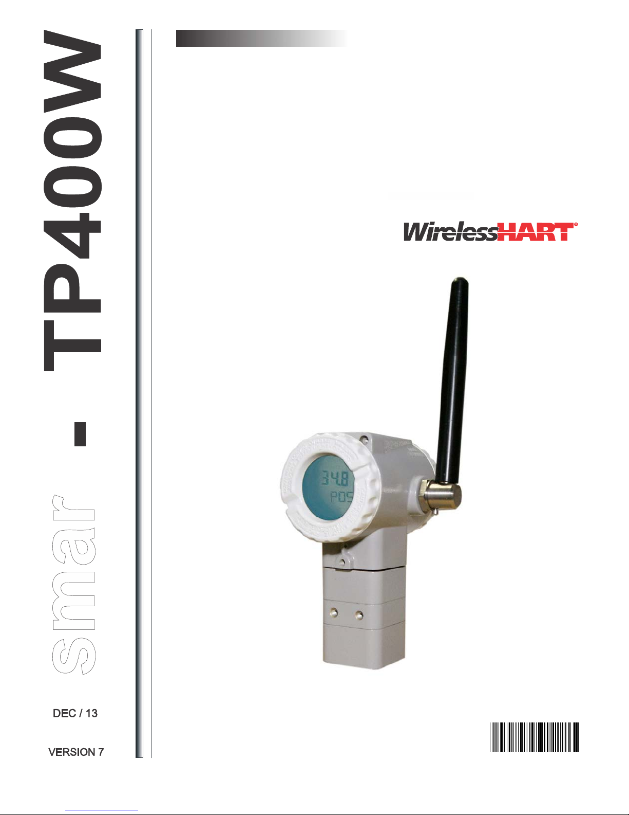
OPERATION, MAINTENANCE AND
INSTRUCTION MANUAL
TM
Wireless
HART
Position Transmitter
TP400
TP400WME
Page 2

r
sma
Specifications and information are subject to change without notice.
Up-to-date address information is available on our website.
web: www.smar.com/contactus.asp
www.smar.com
Page 3

Introduction
t
r
c
r
y
NOTE
This manual is compatible with version 7.XX, where 7 indicates software version and XX software release. The
indication 7.XX means that this manual is compatible with any release of software version 7.
Waiver of responsibility
The contents of this manual abides by the hardware and software used on the current equipmen
version. Eventually there may occur divergencies between this manual and the equipment. The
information from this document are periodically r eviewed and th e necessar y or identified correcti ons
will be included in the following editions. Suggestions for their improvement are welcome.
Warning
For more objectivity and clarity, this manual does not contain all the detailed information on the
product and, in addition, it does not cover every possible mounting, operation or maintenance
cases.
Before installing and utilizing the equipment, check if the model of the acquired equipment complie s
with the technical requirements for the application. This checking is the user’s resp onsibility.
If the user needs more information, or on the event of specific problems not spec ified or treated in
this manual, the information should be sought from Smar. Furthermore, the user recognizes that the
contents of this manual by no means modify past or pres ent agreements, confirmation or judicial
relationship, in whole or in part.
All of Smar’s obligation result from the purchasing agreement signed between the parties, which
includes the complete and sole valid warranty term. Contractual claus es related to the warrant y are
not limited nor extended by virtue of the technical information contained in this manual.
Only qualified personnel are allowed to participate in the activities of mounting, electrical connection,
startup and maintenance of the equipment. Qualified personnel are understood to be the persons
familiar with the mounting, electrical connection, startup and operation of the equi pment or othe
similar apparatus that are technically fit for their work. Smar provides specific training to instruct and
qualify such professionals. However, each country must comply with the local safety procedures,
legal provisions and regulations for the mounting and op eration of electrical installations, as well as
with the laws and regulations on classified areas, such as in trinsic safet y, explosion proof, increased
safety and instrumented safety systems, among others.
The user is responsible for the incorrect or inadequate handli ng of equipments run with pneumati
or hydraulic pressure or, still, subject to corrosive, aggressive or combustible products, since thei
utilization may cause severe bodily harm and/or material damages.
The field equipment referred to in this manual, when acquired for classified or hazardous areas, has
its certification void when having its parts replaced or interchange d without functional and approva l
tests by Smar or any of Smar authorized dealers, which are the com petent companies for certifyin g
that the equipment in its entirety meets the applicable stan dards and regulations. The same is true
when converting the equipment of a communication protocol to anot her. In this case, it is necessar
sending the equipment to Smar or any of its authorized dealer. Moreover, the certificates are
different and the user is responsible for their correct use.
Always respect the instructions provided in the Manual. Smar is not responsible for any losses
and/or damages resulting from the inadequate use of its equipments. It is the user’s res ponsibilit y to
know and apply the safety practices in his country.
III
Page 4

TP400 WirelessHARTTM - Operation, Maintenance and Instructions Manual
TABLE OF CONTENTS
SECTION 1 - INSTALLATION ....................................................................................................... 1.1
GENERAL .................................................................................................................................. 1.1
INSTALLATION PROCEDURE .................................................................................................. 1.1
ANTENNA ROTATION ............................................................................................................... 1.6
HOUSING ROTATION ............................................................................................................... 1.7
MAINTENANCE PORT .............................................................................................................. 1.8
LINEAR ROTARY AND LINEAR MAGNET ................................................................................ 1.9
CENTRALIZER DEVICE OF LINEAR MAGNET ........................................................................ 1.9
REMOTE SENSOR POSITION .................................................................................................. 1.9
INSTALLATION IN HAZARDOUS AREAS ............................................................................... 1.11
INTRINSICALLY SAFE ............................................................................................................ 1.11
SECTION 2 - OPERATION ............................................................................................................ 2.1
FUNCTIONAL DESCRIPTION - POSITION SENSOR ............................................................... 2.1
FUNCTIONAL DESCRIPTION - ELECTRONICS ....................................................................... 2.1
LOCAL ADJUSTMENT ............................................................................................................... 2.3
WRITE PROTECTION ............................................................................................................... 2.4
FUNCTIONAL DESCRIPTION - DISPLAY (LCD) ...................................................................... 2.5
SECTION 3 - MAINTENANCE ....................................................................................................... 3.1
GENERAL .................................................................................................................................. 3.1
DIAGNOSTIC WITH DISPLAY ................................................................................................... 3.1
DISASSEMBLY PROCEDURE .................................................................................................. 3.1
ASSEMBLY PROCEDURE ........................................................................................................ 3.3
TROUBLESHOOTING ............................................................................................................... 3.4
EXPLODED VIEW ...................................................................................................................... 3.5
ACCESSORIES AND SPARE PARTS ....................................................................................... 3.5
RETURNING MATERIALS ......................................................................................................... 3.7
SECTION 4 - TECHNICAL CHARACTERISTICS ......................................................................... 4.1
ORDERING CODE ..................................................................................................................... 4.3
APPENDIX A – SRF – SERVICE REQUEST FORM .................................................................................. A.1
APPEDIX B – BATTERY SAFETY DATASHEET ...................................................................................... B.1
IV
Page 5
INTRODUCTION
WirelessHART Technology Overview
The WirelessHART technology is based on a wireless mesh network communication protocol used in
process automation applications. It adds wireless capabilities to the HART protocol, while maintaining
compatibility with existing HART devices, commands and already known and used tools.
WirelessHART network
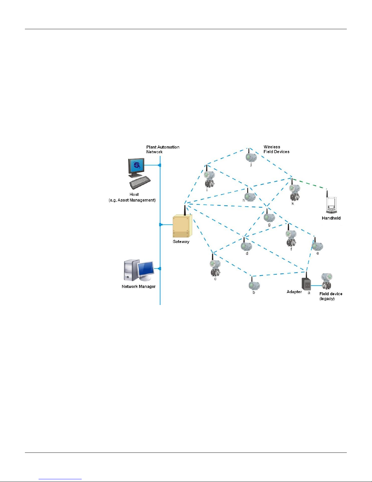
Basically, a WirelessHART network, defined in the HART specifications, consists of a host, a
WirelessHART Gateway and one or more field devices and/or WirelessHART adapters. Together they
compose a mesh network where the host and devices can communicate.
Introduction
Host
The host, usually connected to the control network, is a workstation in which, e.g., can be installed a
Human Machine Interface application, which allows an operator to interact with the process. Through the
WirelessHART Gateway (DF100), the host can gather data from devices connected to the
WirelessHART network. The host communicates with the WirelessHART Gateway (DF100) using a
communication protocol, for example, HSE, H1, Profibus or Modbus.
WirelessHART Gateway (DF100)
It is a "translator" equipment. Thus it converts data from the host to the WirelessHART protocol, used by
the devices connected to the WirelessHART network, and converts data from the de vices to the host. In
general, the WirelessHART Gateway (DF100) incorporates the features of Network Manager and
Access Point. Roughly, the access point can be understood as the WirelessHART radio installed at the
gateway to communicate with devices connected to the wireless network.
Security Manager
The Security Manager is an application usually embedded in the WirelessHART Gateway (DF100).
Allowed only one Network Manager in a WirelessHART netw ork, but the same Security Manager can
serve several WirelessHART networks.
Its main function is to create, store and manage security keys (encryption and authentication) for which
the devices have network access and monitor the status of network security.
V
Page 6

TP400 WirelessHARTTM - Operation, Maintenance and Instructions Manual
Network Manager
The Network Manager is an application that can be embedded in the WirelessHART Gateway. On a
WirelessHART network is only allowed to have one Network Manager. Among its responsibilities, the
Network Manager distributes network identity (advertisement) publishing its existence, manages and
authenticates the addition (joining) of devices to the network. It also distributes individual security keys
(static or rotating) to the devices to ensure secure communication between it and the devices. The
Network Manager assigns communication band to the devices already connected to the network that
requested services to it, as well as manages the routes between the devices on the mesh network.
Specifically about the joining process of a WirelessHART device to the network, the Network Manager
validates the Network ID and the Join Key attributes which are configured in the WirelessHART Gatewa y
and WirelessHART devices.
The Network ID identifies a WirelessHART network in unique way. It is an unsigned inte ger attribute
and must be configured on the WirelessHART Gateway and all WirelessHART devices. Considering a
WirelessHART network installed in a plant, the permitted values for the Network ID ranges from 0 (hex
0x0000) to 32767 (0x7FFF hexadecimal).
The Join Key is a security key used to encrypt joining requests from WirelessHART devices that receive
the advertisement with the Network Id identical to theirs. It may be single or each WirelessHART device
may be configured with an individual Join Key. In the first case, the WirelessHART Gateway and all
WirelessHART devices must be configured with the same Join Key. In the second case, which provides
higher communication security level, (a) must be configured in the WirelessHART Gateway a list with
individual Join Keys, i.e., a key for each WirelessHART device, and (b) you must configure each
WirelessHART device with its individual Join Key. The Join Key is a hexadecimal string of 16 bytes.
There is no restriction to the hexadecimal value of each byte. The table below shows ex amples of some
join keys.
JOIN KEYS 16-BYTE HEXADECIMAL STRING
00000000000000000000000000000000 0x00, 0x00, 0x00, 0x00, 0x00, 0x00, 0x00, 0x00,
00000000000000000000000000000302 0x00, 0x00, 0x00, 0x00, 0x00, 0x00, 0x00, 0x00,
00000000FFFFFFFF0000000000000000 0x00, 0x00, 0x00, 0x00, 0xFF, 0xFF, 0xFF, 0xFF,
550000000000000000000000000000AA 0x55, 0x00, 0x00, 0x00, 0x00, 0x00, 0x00, 0x00,
WirelessHART device
The WirelessHART field device is the device that connects to the process, being able to receive and/or
transmit data on the WirelessHART network. It is a WirelessHART router (repeater) by nature, i.e., it is
able to retransmit messages to/from other devices on the WirelessHART network.
WirelessHART Adapter
It is a bridge-type device, because it is able to provide data of HART + 4 to 20mA field device, legacy, to
the host via WirelessHART. The adapter uses HART FSK standard communication, wired, to access
data from HART field devices. And the adapter also uses the WirelessHART communication to provide
data of the field device to the host. The adapter thus enables a HART field device to work on
WirelessHART network.
Planning a WirelessHART network
The planning of a WirelessHART network is a task that is very similar to the activities that currently we
perform with conventional wired devices. Furthermore, due to the simplicity of a mesh WirelessHART
network, is exempt, in general, detailed field surveys, which are usually needed w hen we plan networks
based on other wireless technologies.
Basically, a WirelessHART network involves planning, design, installation and commissioning phases.
Planning
This phase requires the execution of the following steps:
VI
0x00, 0x00, 0x00, 0x00, 0x00, 0x00, 0x00, 0x00
0x00, 0x00, 0x00, 0x00, 0x00, 0x00, 0x03, 0x02
0x00, 0x00, 0x00, 0x00, 0x00, 0x00, 0x00, 0x00
0x00, 0x00, 0x00, 0x00, 0x00, 0x00, 0x00, 0xAA
Page 7
Introduction
Scope definition
Clearly define the scope of the network. Answer the question: why do we need the wireless netw ork? To
monitor process variables or to implement a non-critical control? The answer to this question will
facilitate the understanding between the team members responsible for the network and determine one
or more process units in the plant. For each process unit, allocate a gateway with unique and specific
Network ID. Outline the main field devices.
Identify potential sources of interference
Are there radio communications or other wireless networks in the plant? What protocols and frequencies
do they use? Use high power? Although unlikely, given the robustness of the radios used by the
WirelessHART technology, prior knowledge of the answers to these questions may identify potential
sources of interference and to indicate the taking of preventive and/or limiting actions even before
installation. For example, you can select a frequency channel as unavailable, adding it to the black list of
frequencies that is under the WirelessHART Network Manager control.
Integration with the host
The gateway connects the WirelessHART field devices to the host system. Plan what devices and what
data are needed. Also, the stations or applications which will process the data have to be clearly
defined. From this set, among the protocols in the system, define which one will be used for integration
with the host and with the existing tools for configuring the devices. After defining the protocol for
integration, the user has to choose the gateway on the market that best meets your requirements. Smar
offers the Gateway DF100 that supports Modbus/TCP/HSE.
Project
In the project phase, it is recommended the adoption of the practices below. Although conservative,
these practices ensure robustness and scalability to the network.
o Define the Network ID that will be used for all devices in the process unit;
o Define if the Join Key will be common to all devices or individual and dedicated ;
o Define the policy to be used for the definition of devices (Long) Tags;
o Use a scale drawing of the process unit;
o Place the gateway in a strategic position in the process unit ;
o Plan networks with at least five devices;
o Install at least five devices within the gateway coverage area;
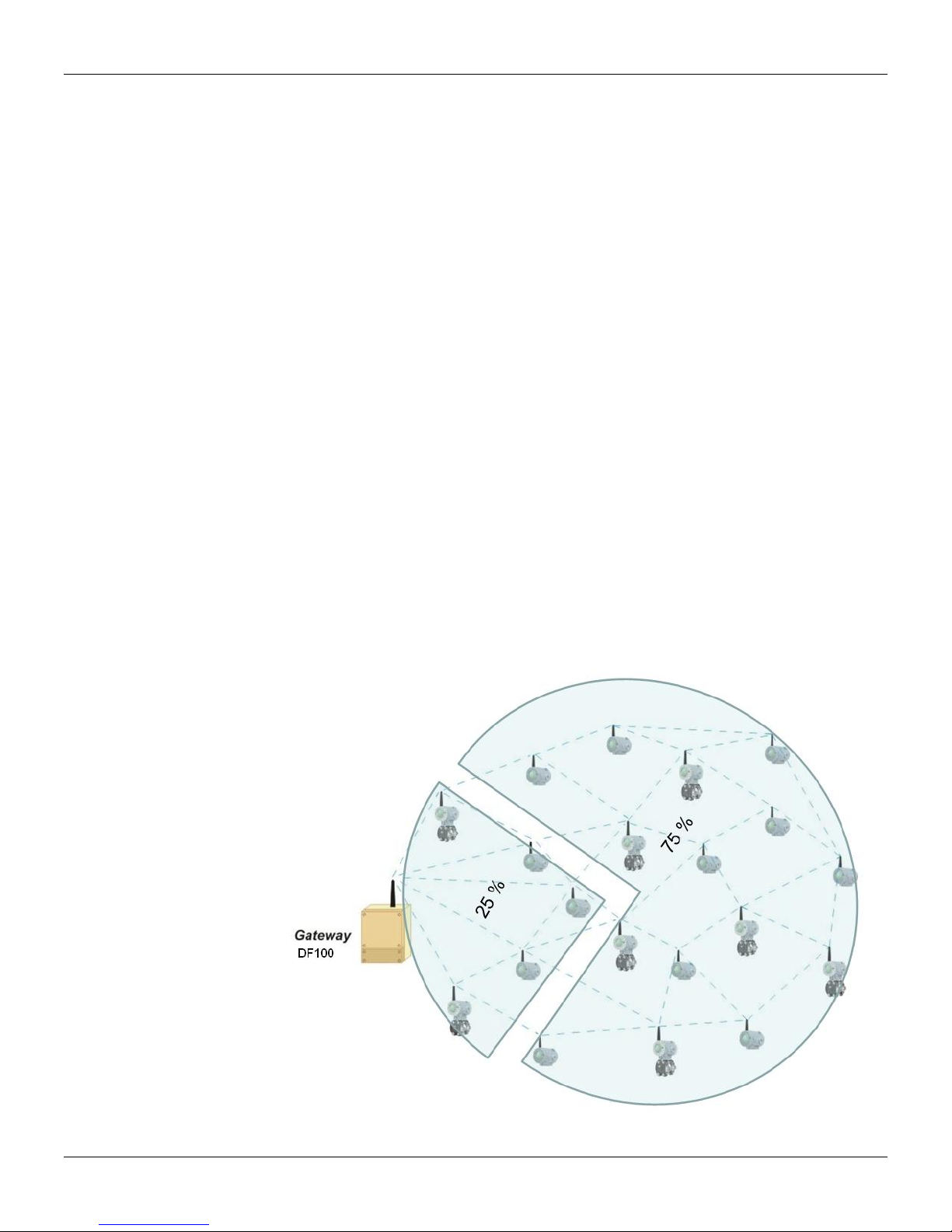
o Ensure that 25 % of the devices are within the gateway coverage area;
Gateway coverage area
VII
Page 8
TP400 WirelessHARTTM - Operation, Maintenance and Instructions Manual
o Reposition the gateway as needed ;
o Check the coverage area of each device;
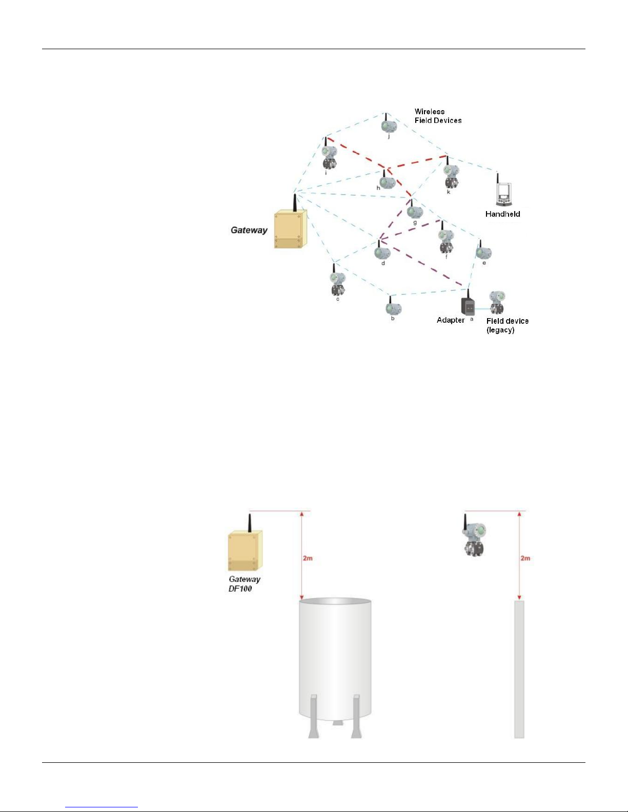
o Ensure that each device has three neighbors within its coverage area;
WirelessHART devices vicinity
o Place the repeaters as needed.
Installation
As mentioned before, WirelessHART devices should be connected to the process and configured the
same way as conventional wired HART devices. Handheld terminals can be used normally. Just be sure
of having it properly uploaded with the latest DD files of the devices. However, it is known that the
WirelessHART devices have characteristics inherent to the technology. Because of this, it is
recommended the adoption of practices mentioned below for positioning the gateway and devices.
o Install the gateway and the devices so that their antennas are vertical;
o Ensure that the antennas are at 0.5 m minimum distance of large obstacles or surfaces ;
o Ensure that the antennas of gateway and repeaters are 2 m above most obstacles within their
coverage areas;
VIII
Gateway and repeater 2m above the obstacles
Page 9
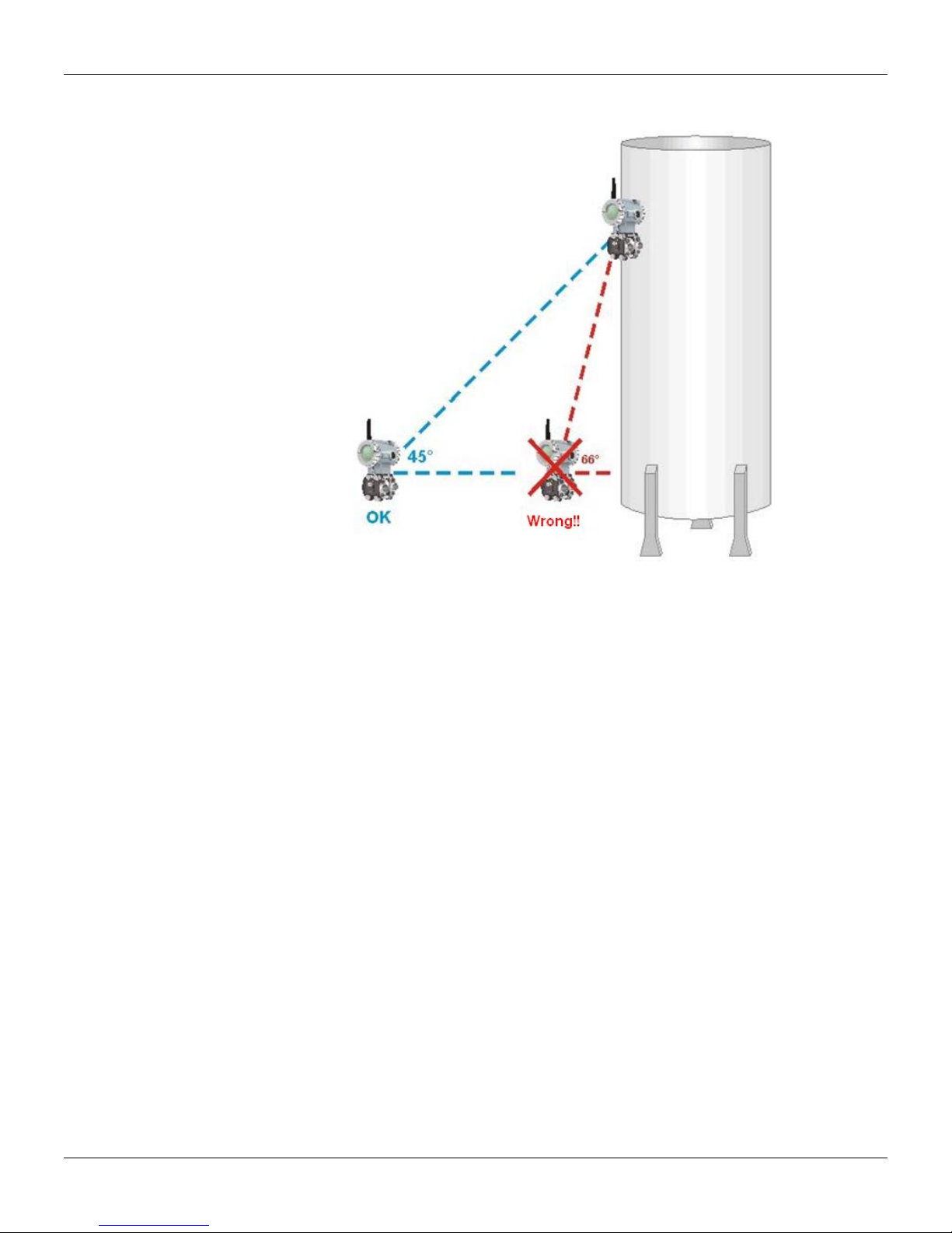
o If there are high devices, does not exceed 45° viewing angles between them;
Introduction
Device’s viewing angle
o Make sure that the gateway is integrated to the host system as planned.
Commissioning on Bench
Commissioning consists on testing the device and verifying its configuration data. The TP400
WirelessHART can be commissioned either before or after installation. The commissioning of the
device in bench before its installation using CONF401, HPC401 or any DD-based configurator, e.g.
Smar AssetView, ensures that all transmitters’ components are working properly.
To turn on/off the repeater use the terminal SW1 (ON/OFF), as shown in Figure 1.7.
To connect the handheld to the device, use the communication terminals "CN1 and CN2" on the
terminal block. See Figure 1.7.
Commission the devices and gateway.
WirelessHART devices commissioning
a. Install and power the gateway (DF100)
b. If not specified by the client at time of order, the Network ID and Join Key values of gateway and
devices will be the factory default values. Note: It is strongly recommended that both be changed! To
change these parameters install the gateway and all network devices following the steps below.
Once the network is fully operational it will be more practical to change them.
c. The devices configuration must be done individually, starting with those nearest to the gateway and
further to the most distant so that communication is established correctly.
d. Always install the device with the antenna in the vertical direction. None WirelessHART device must
be located at the highest point of the plant, preventing it to work as possible lightning rod;
e. Turn on the device by the switch at left of the display and wait for its connection to the network (this
time can vary from 2 to 20 minutes depending on the network size). The device status on the
network can be verified on display, maintenance port or gateway.
IX
Page 10

TP400 WirelessHARTTM - Operation, Maintenance and Instructions Manual
ATTENTION
If the device was not purchased with the gateway, i.e. the gateway already has values of Network ID and
Join Key different from the default values, it is necessary to set these parameters in the device so that it
properly connects to the network: first configure Network ID and then Join Key, restarting the device
after settings.
f. Once these steps are performed for all network devices and they are connected properly, it is time
to change the values of Network ID and Join Key from factory following the instructions at the end of
step "e" (if not changed yet). Network ID can be any number between 0 and 32767 which identifies
the network among others. Join Key is a key of 32 hexadecimal characters (0-9 and AF) that works
as a key so the devices can have access to the configured network.
g. Configure the LongTAG parameter that identifies the device on the network.
h. Check if the device engineering units are in accordance with those required by the process.
i. Configure the parameters of the burst mode to publish measurements and status desired:
Burst Message: up to 3 messages with commands and different times can be configured;
Minimum Time : is the time for publication of the variables;
Maximum Time: must be greater than the minimum time and is only used in trigger mode (check
the operation of the trigger mode in the device manual if you want to receive the monitoring
variables only when there is any change on their values);
Command: HART command that sends the variables desired by user (e.g. , the command 3
sends values of PV, SV, TV and QV, when available);
Burst Mode: Once all parameters have been configured, activate Burst mode.
Acquisition based on Burst time parameter that reduces the consumption of the device to
perform only one acquisition immediately before the burst transmission. If this parameter is
disabled, the device will execute an acquisition every two seconds, regardless of the Burst
Minimum Time.
j. After some time negotiating with the gateway, the device will start publishing the configured
command at a minimum time rate configured. The ACK icon is shown on the display (if available)
when the device enters in Burst Mode and the icon F(t) blinks on the moment that the command
burst is sent.
ATTENTION
The Burst mode configurations remain even after the shutdown of the device, i.e., when it is turned on,
the device connects to the network automatically in Burst mode with the same time and command
configured. The higher the refresh rate, the lower the lifetime of the battery and vice versa. Configure a
refresh rate that allows the device to last few years.
k. After the general network configuration, wait a period of about 1 hour for the network starts to
operate 100% optimized.
ATTENTION
There is a battery estimated lifetime parameter that indicates the expected duration in days of the
device. This parameter is recalculated every 60 minutes and its value should only become valid after
two or three hours of operation of the device on the network (time required for consumption
optimization). When this value is near the end, the user will receive a warning in the device status and in
the display (when available). When you replace the Battery Module (Smar code 400-1209) you have to
configure the replacement via configurator that will restart the counting of the estimated lifetime for the
new module.
ATTENTION
Do not discard the Module of Batteries in regular trash. Use a proper disposal for batteries or chemical
waste.
X
Page 11

Verifying the Range of Device
Identify which distance to be considered according to the type of environment to install the device:
To mount the device near the ground, below ground level or under water, since the RF signal is
absorbed into soil or water and does not propagate, can significantly reduce the range of the devices.
Additionally, to mount the device outside the network area (gateway), for example, considering a
network in an open environment and installing the device inside a closed room, also contributes to signal
attenuation, because signal will not propagate very well within concrete, wood, etc.
Gateway commissioning
The gateways can have a remote connection to the antenna, allowing them to be installed indoors and
only the antenna is in the network environment .
a) Make sure that the gateway is available to the host system;
b) Check the gateway and make sure it has at least five devices directly connected to it;
c) Check if 25 % of the devices are connected directly to the gateway. If necessary, add repeaters;
d) The gateway connects the devices to the host system. Thus, check if the data of the devices are
We recommend a visit to the HART Communication Foundation website for additional information about
the WirelessHART protocol such as WirelessHART project planning, positioning of devices,
commissioning and verification tools, and practices.
TP400 WirelessHART
The TP400 is a WirelessHARTTM transmitter for position measurement and it is part of the family of
Smar devices.
It can measure displacement or movement of rotary or linear type based on Hall effect non-contact
sensor. The digital technology and wireless communication provide an easy interface between the field
and control room and several interesting features that considerably reduce the installation, operation
and maintenance cost.
The TP400 WirelessHART
equipment with linear or rotary motion such as skylights, dampers, rollers spacing, crushers, etc. There
is an option for remote sensor with cable length up to 20 m.
The Remote Sensor Position is a recommended accessory for high temperatures applications (up to
105 ºC), for excessive vibration or even difficult local access. It avoids equipment excessive wear and,
consequently, increases the equipment lifetime. The cable supplied by Smar is shielded and provides
excellent protection against electromagnetic interferences.
Introduction
Strong Obstruction - about 30 m (10 ft.). Very dense environments in relation to devices, pipes,
cables, etc. Consider a place where you are not normally able to travel.
Average Obstruction - about 75 m (25 ft.). Environment which have space among devices in
relation to the rest of the plant.
Light Obstruction - 150 m (50 ft.). Consider an open environment that has some kind of
obstruction such as a silo or a tank. Although the obstruction is large, around the obstacle there
is enough free space for propagation of the RF waves.
Line of Sight - up to 225 m (75 ft.). Consider that the antenna’s device "sees" directly the
antenna of another network device, without any obstacle between them. Furthermore, the height
difference between them should not have an angle greater than 5 degrees.
coming to the applications that subscribe them.
TM
may be installed to monitor valves and actuators position or in any
XI
Page 12

TP400 WirelessHARTTM - Operation, Maintenance and Instructions Manual
XII
Page 13

Section 1
A
A
A
A
INSTALLATION
General
Installation Procedure
For hazardous area installations the IEC 60079-14 standard recommendations must be follow.
Although the TP400 has an outstanding performance, proper installation i s essential to maximize its
efficiency.
Humidity is fatal to electronic circuits. In areas subjected t o high relative humidity level the O-rings
for the electronic housing covers must be in good conditions and corr ectly placed. The covers must
be completely closed by hand until the O-rings are compressed. Avoid using tools for this operation.
Removal of the electronics cover in the field should be avoided in order to protect elect ronic circuit
from humidity.
The electronic circuit is protected by a humidity proof varnish but frequent exposures to humidity
may affect the protection provided. It is also important to keep the covers tightened in place. Every
time they are removed, the threads are exposed to corrosion, since thes e parts ar e not pr otected b y
painting.
Do not remove cover grease to avoid stuck housing.
Common cause, random or often failures should not damage the device or result in death and serious injury,
harm the environment or result in loss of production or devices.
Electrical discharge can result in death and serious injury.
The position transmitter is designed to be lightweight and robust at the sa me time, allowing an easy
installation. The following figures show the dimensions and usual mounting positions of the p osition
transmitter.
The TP400 WirelessHARTTM must always be installed with the antenna positioned upwards.
Do not rotate the antenna, because the cable may break.
To access the display and the main board remove the front cover. This cover can be locked by the
cover locking screw. To release the cover, rotate the locking screw clockwise. See Figure 1.10.
The TP400 mounting depends on the type movement, linear or rotar y. T wo brackets are requ ired for
mounting, one for the magnet and the other for the transmitter itself.
Make sure that arrow engraved on the magnet coincides with the arrow eng raved on the Position Transmitter
when the system is in mid travel.
When mounting the the Position Transmitter, consider that:
1. There is no attrict between the internal magnet face and the position sensor salience all over the travel
2. The magnet and the salience of position sensor must not be distant.
A minimum distance of 2 mm and a maximum distance of 4mm are recommended between the magnet
external face and the transmitter face. For that, a centralizer device (linear) must be used. The centralizer
device is in the transmitter packing.
Should the position transmitter installation change, or magnet change, or should any other
modification, the transmitter will require a re-calibration.
NOTE
TTENTION
TTENTION
TTENTION
TTENTION
NOTE
(rotary or linear).
1.1
Page 14
TP400 WirelessHARTTM – Operation and Maintenance Instruction Manual
S
Rotary Movement
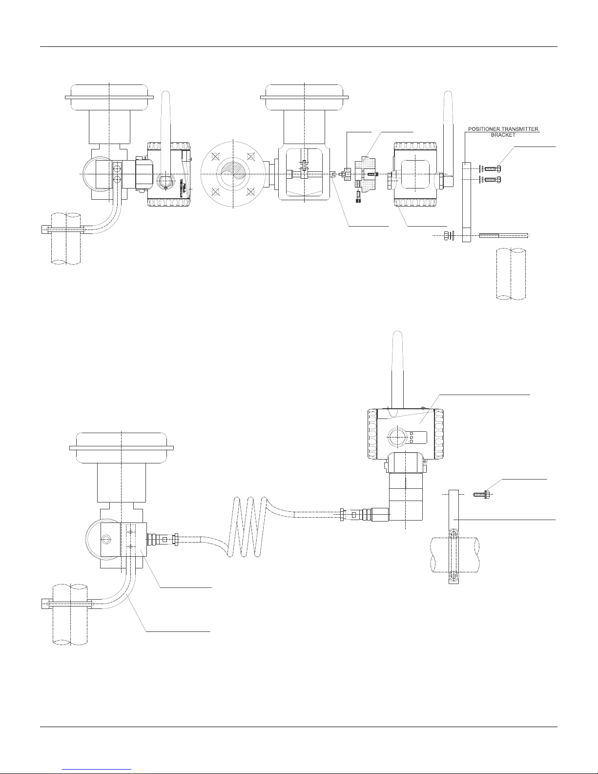
Install the magnet on the valve stem using the magnet mounting bracket.
ROTATY
MAGNET
BRACKET
ROTARY
MAGNET
M6x1 SCREW
(4 PLACES)
VALVE STEM
POSITIONER
TRANSMITTER
Figure 1.1 - Transmitter on a Rotary Actuator
REMOTE POSITION TRANSMITTER
1/2 NPT
M20x1.5
PG 13.5
M6x1 SCREWS
(2 PLACES)
REMOTE SENSOR
BRACKET FOR REMOTE
SENSOR
Figure 1.2 – Position Transmitter on Rotary Actuator with Remote Position Sensor
1.2
“L” BRACKET WITH “U” CLAMP FOR
REMOTE POSITION TRANSMITTER
Page 15
Installation
Linear Movement
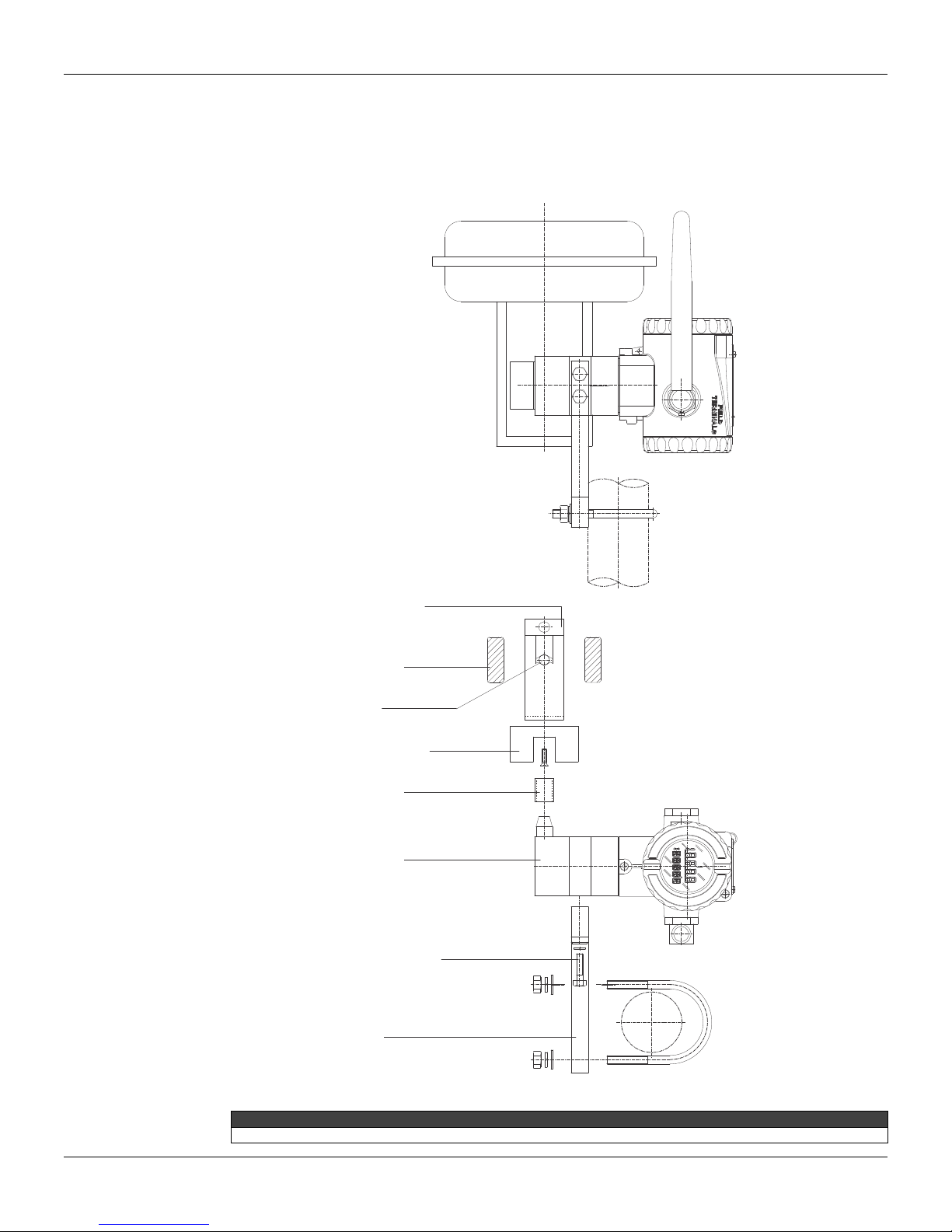
Install the magnet on the valve stem using the magnet mounting bracket.
The linear magnet movement must be orthogonal (90º) in relation to the main axis of the position
transmitter. For example, if the linear magnet movement is vertical, the transmitter main axis must
be horizontal, as show in Figure 1.3.
MAGNET BRACKET
LINEAR
VAL VE YOKE
VALVE STEM
LINEAR MAGNET
CENTRALIZER GADGET
LINEAR
POSITION TRANSMITTER
M6 x 25 SCREWS
(2 PLACES)
POSITION TRANSMITTER BRACKET
WITH CLAMP
“U”
“L”
Included in the package content the centralizer device of linear magnet. See figure 1.14
Figure 1.3 - Transmitter on a Linear Actuator
NOTE
1.3
Page 16
TP400 WirelessHARTTM – Operation and Maintenance Instruction Manual
f
“L” BRACKET WITH “U” CLAMP
FOR REMOTE SENSOR
LINEAR MAGNET
BRACKET
VALVE YOKE
VALVE STEM
LINEAR MAGNET
LINEAR CENTRALIZER
DEVICE
REMOTE SENSOR
or
REMOTE POSITION TRANSMITTER
1/2 NPT
M6x1 SCREWS
(2 PLACES)
M20x1.5
PG 13.5
“L” BRACKET WITH “U” CLAMP FOR
REMOTE POSITION TRANSMITTER
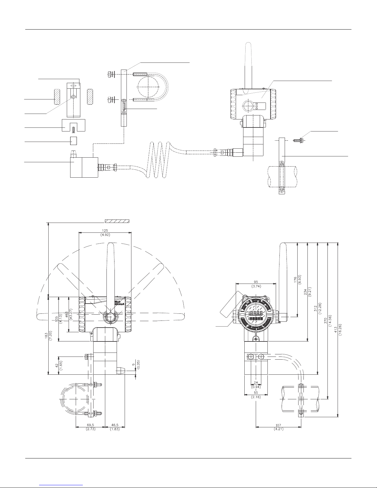
Figure 1.4 – Position Transmitter on Linear Actuator with Remote Position Sensor
M6x1 SCREWS
(2 PLACES)
1.4
Leave, at least, a 150 mm space,
zero and span adjustments with the
magnetic tool.
PLUG
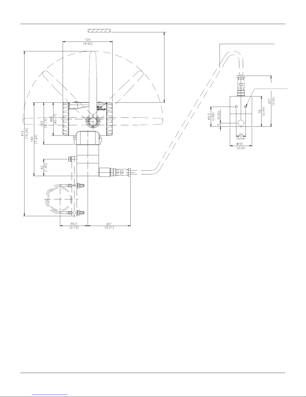
NOTE: DIMMENSIONS IN MILIMETERS (INCH)
Figure 1. 5 – Dimensional Drawing of TP400 WirelessHART
TM
in mounting in vertical
Page 17
Installation
S
FLEXIBLE SHIELDED CABLE
AVAILABLE LENGHTS:
5 m, 10 m, 15 m, 20 m
Leave, at least, a 150 mm space, for
zero and span adjustments with the
magnetic tool.
THREADS FOR SCREW
M6X1
Figure 1.6 - Dimensional Drawing of TP400 WirelessHARTTM with Remote Sensor
1.5
Page 18
TP400 WirelessHARTTM – Operation and Maintenance Instruction Manual
Antenna Rotation
1.6
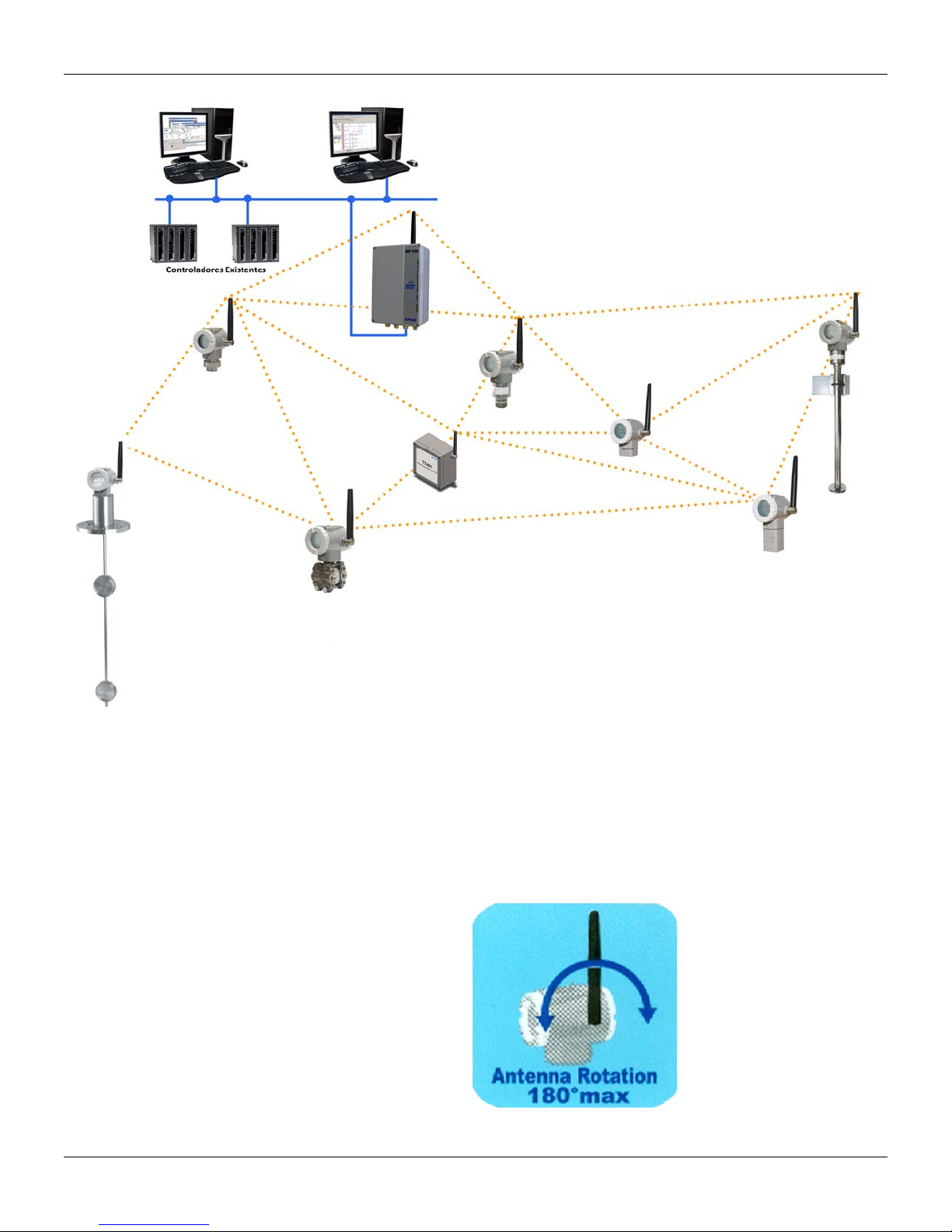
Figure 1.7 – Arrangement scheme of WirelessHART devices
The antenna does not have rotation limits to allow easier device installat ion in several areas and
positions. However, it is suggested that its movement is restricted to the upper 180° (90° left and
90° right with the device vertically) identified by the label on the device. See the next figure.
Figure 1.8 – Antenna rotation limits
Page 19
Installation
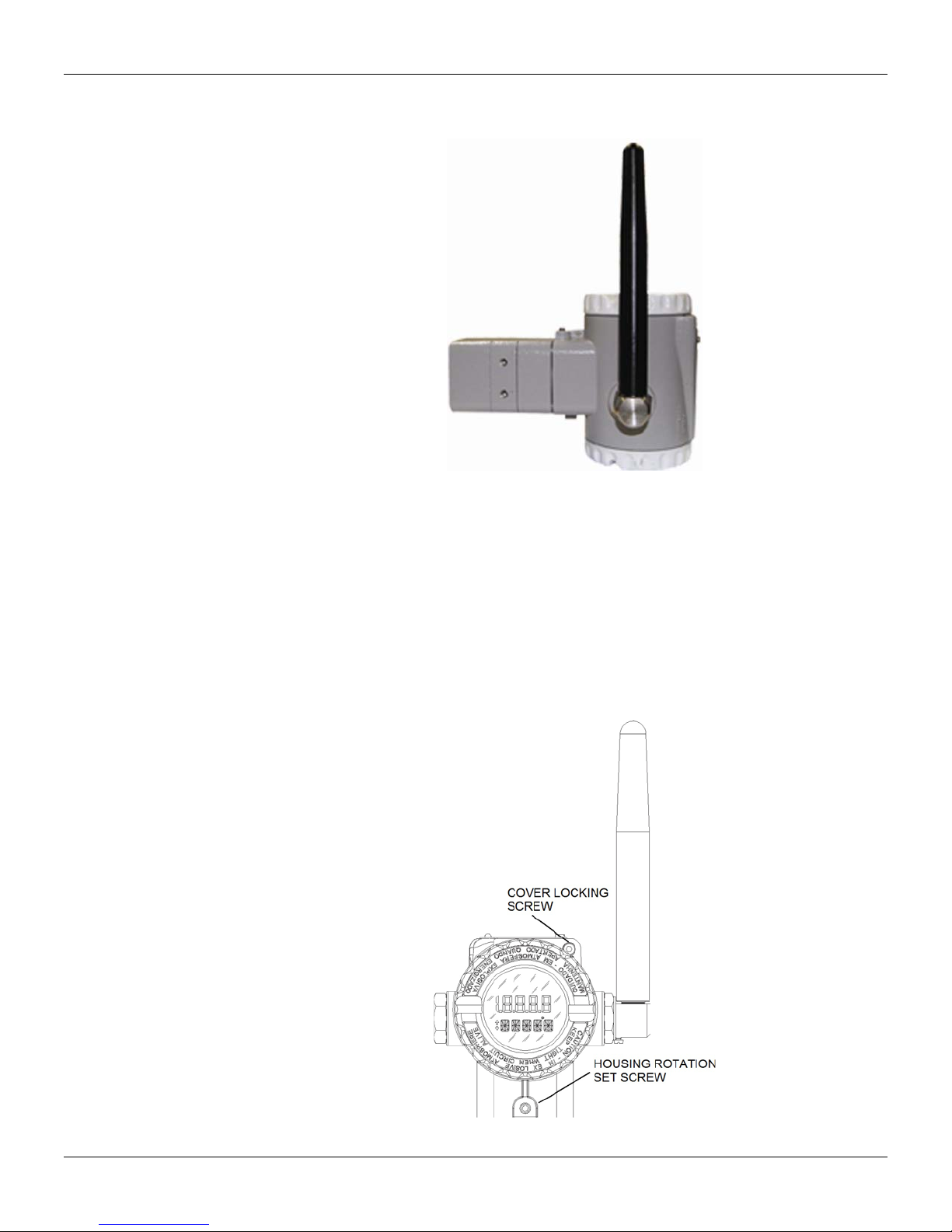
In case of horizontal mounting adjust the antenna to the vertical position, as shown in following
figure.
Housing Rotation
Figure 1.9 – Correct position of the antenna with device horizontally
If the mounting position does not allow rotation of the antenna to a vertical position, the housin g
must be rotated until the rotational movement of the antenna to the vertical position is reached.
It is of utmost importance for the quality of the WirelessHART network signal transmission that the
antenna stays on the vertical position..
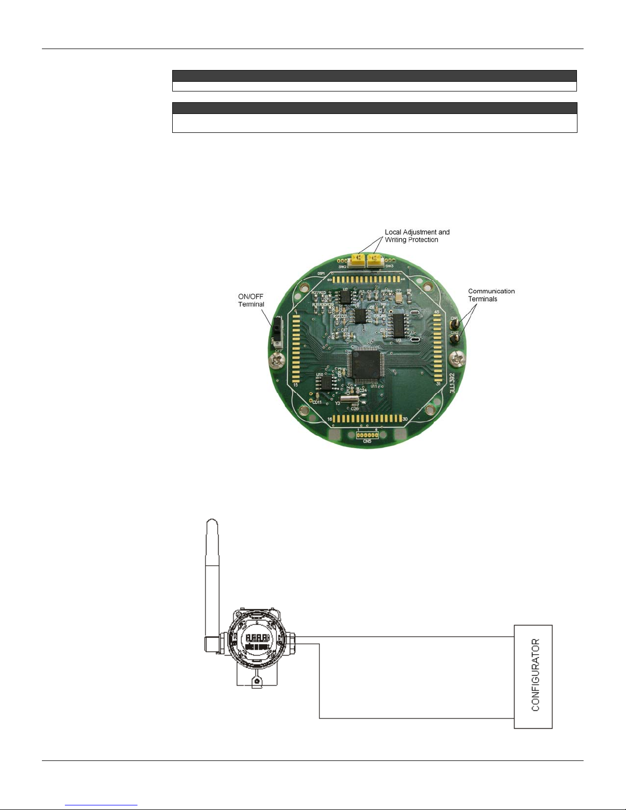
The housing can be rotated to adjust the digital display on a better position. To rotate it, loose the
housing rotation set screw, see next figure.
Figure 1.10 – Housing rotation set screw and cover locking screw
1.7
Page 20
TP400 WirelessHARTTM – Operation and Maintenance Instruction Manual
The TP400 WirelessHARTTM must always be installed with the antenna positioned upwards.
To prevent humidity or corrosive gases entering, tighten the cover until it touches the housing. Then, tighten
more 1/3 turn (120º) to guarantee the sealing. Lock the covers using the locking screw.
Maintenance Port
The communication port allows local communication with the position transmitter using a HART
configurator connected to communication terminals "CN1" and "CN2" which ar e shown in the next
figure.
NOTE
NOTES
Figure 1. 11 – Position transmitter maintenance port
A configurator can be connected to the communicati on terminals of the position transmi tter through
its connection terminals.
Figure 1.12 – Wiring Diagram of configurator to TP400 WirelessHAR T
TM
1.8
Page 21
Linear Rotary and Linear Magnet
Li
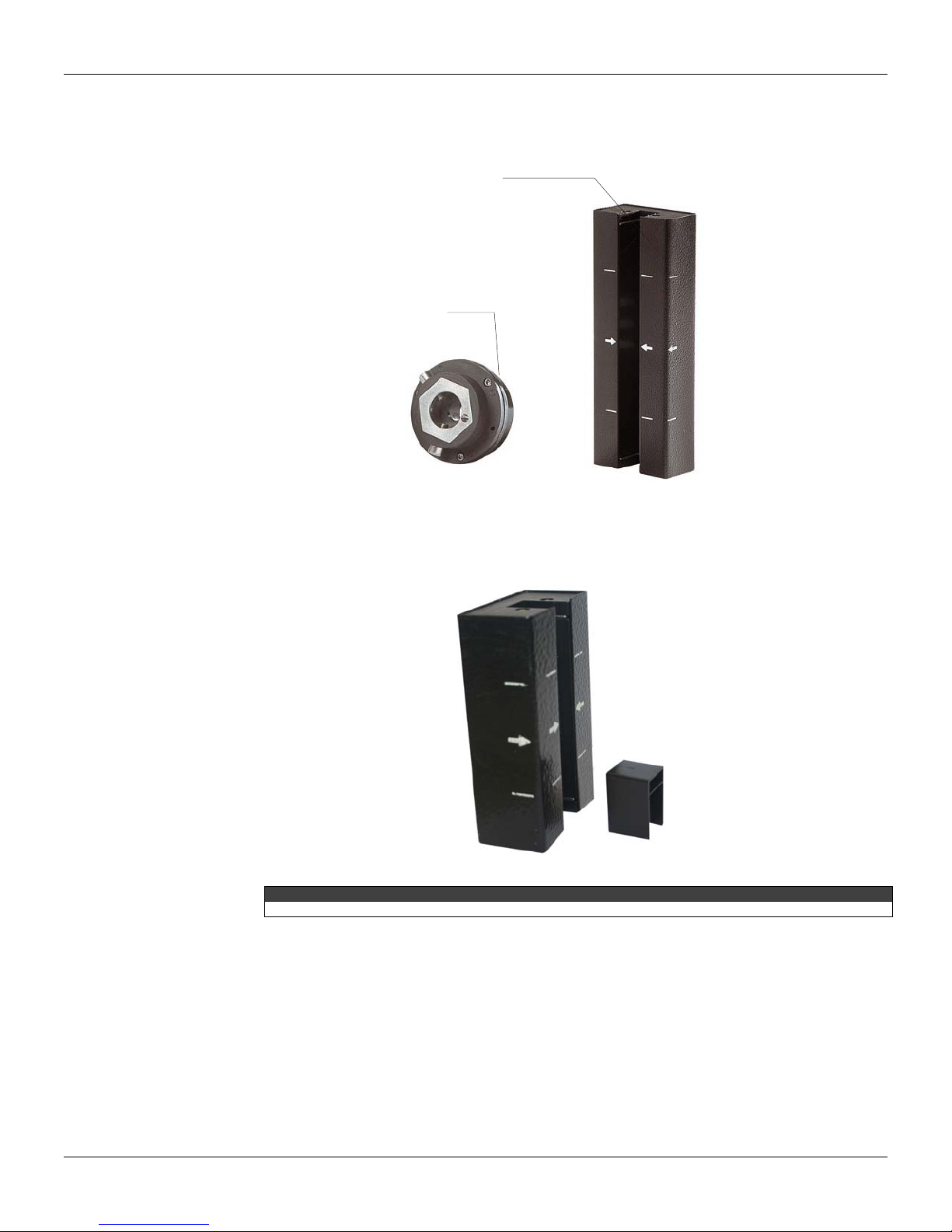
The models are linear and rotary magnet for use in linear and rotary actuators, respectively.
Installation
near Magnet
Rotary Magnet
Figure 1.13 – Linear and Rotary Magnet Models
Centralizer device of linear magnet
Centralizer device of linear magnet is used for all type of linear bracket.
Figure 1.14 - Centralizer device of linear magnet
Remote Sensor Position
The remote sensor potion is an accessory recommended for high temperature and extreme
vibration applications. It prevents excessive wear of the equipment and, consequentl y, the reduction
of its lifetime.
For an appropriate installation of the sensor, check if the engraved arro w on the magnet matches
the position transmitter arrow when the valve is at half way course.
The magnet mounting in relation to the position sensor should follow proc edure below:
NOTE
1.9
Page 22
TP400 WirelessHARTTM – Operation and Maintenance Instruction Manual
1. There is no friction between the magnet internal face, linear of rotary, and the remote
position sensor bulge when excursioning for opening or closing the valve.
2. The magnet and the remote sensor b ulg e are not too far.
It is recommended to keep a minimum 2 mm space and maximum 4 mm distance between the
magnet external face and the remote sensor face. There is a centralizing device, for both linear
installations, inside the position transmitter packing which will help you to correctly install the
position transmitter and remote sensor.
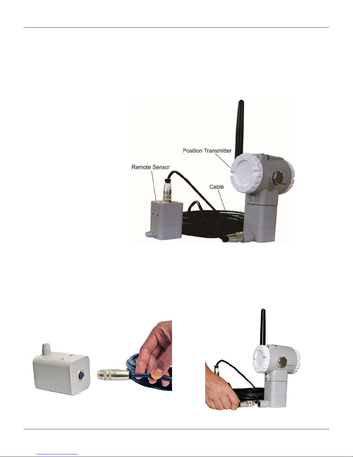
Figure 1.15 - Remote Position Sensor
The electric signals in the remote sensor cable to device are of low intensity. Therefore, when
installing the remote sensor cable inside the conduit (maximum limit 20 meters length), we
recommend to avoid the proximity of possible induction sources and/or magnetic interferenc e. The
supplied cable is shielded for protection against electromagnetic interference, but despite this
protection avoid the cable sharing the same conduit with other cables.
The connector for remote position sensor is e asy handle an d simple install ation. See the installation
procedure as per Figure 1.16:
Figure 1.16 – Connecting the Cable to the Remote
Position Sensor
1.10
Figure 1.17 – Connecting Cable to the Transmitter Positioner
Page 23

Installation in Hazardous Areas
A
A
Explosions can result in death or serious injury besides financial damage. Installation of this
instrument in an explosive environment must be compliant with the national standards and
according to the local environmental protection method. Before proceeding with the installation
match the certificate parameters according to the environmental classification.
The instrument modification or replaced parts supplied by any other supplier than authorized
representative of Smar Equipamentos Industriais Ltda is prohibited and will void th e Certification.
Position Transmitter are marked with options of the protection type. The certification is valid only
when the protection type is indicated by the user. When a specific type of protection is selected,
any other type of protection cannot be used.
To install the housing in hazardous areas at least 6 full turns on cover threads must be
done. The housing must be locked using locking screw (Figure. 1.6).
The cover must be tighten with at least 8 turns to avoid the penetration of humi dity or corrosive
gases until it touches the housing. Then, tighten more 1/3 turn (120º) to guarantee the sealing.
Lock the covers using the locking screw (Figure 1.6).
Intrinsically Safe
In hazardous areas with intrinsically safe and non-incendive requirements the circuit co mponent
parameters and applicable installation procedures must be observed.
For free access to the device in the explosive environm ent, ensure the instruments are in stalled in
accordance with intrinsically safe and non-incendive field wiring practices.
Do not remove the position transmitter cover when in operation.
Installation
TTENTION
TTENTION
1.11
Page 24

TP400 WirelessHARTTM – Operation and Maintenance Instruction Manual
1.12
Page 25
Section 2
OPERATION
TP400 WirelessHART
constantly checks the status of the wireless network.
Functional Description - Position Sensor
The Position Sensor supplies an output voltage proportional to the applied magnetic field. This magnetic
sensor, based on hall effect, is ideal for sensoring linear or rotative position. The mechanical vibrations
do not affect Position Sensor.
Functional Description - Electronics
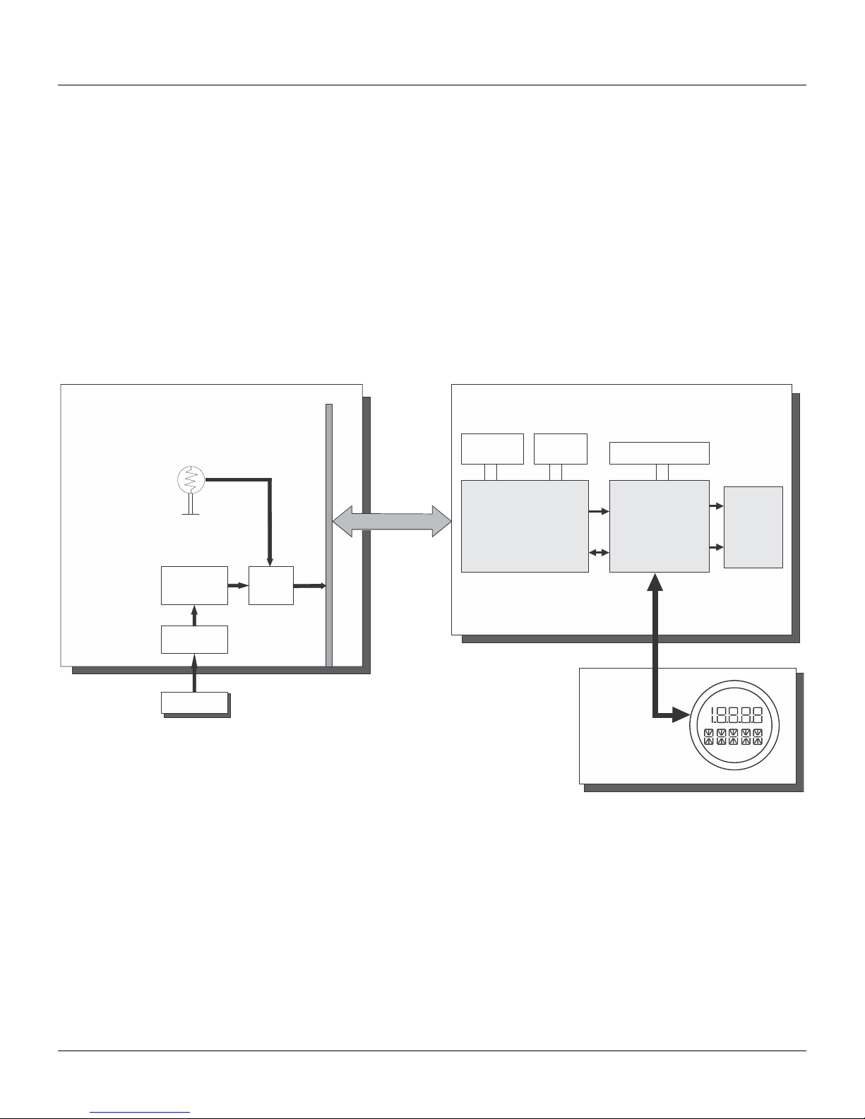
See block diagram
SENSOR BOARD
TM
can measure displacement or movements from rotary or linear type, and
MAIN BOARD
TEMPERATURE
HALL
SENSOR
CIRCUIT
POSITION
SENSOR
MAGNET
DIGITAL READING
A/D
Figure 2.1 - TP400 WirelessHART
Local Adjusment
Zero/Span
PROCESSING UNIT
TM
Block Diagram
RF
Module
Maintenance Port
HART MODEM
LCD CONTROLLER
LCD
BATTERY
MODULE
SENSOR BOARD:
Hall Effect Position Sensor
The magnet, installed in the instrument to the position to be measured, moves the of the instrument
movement accordingly. The hall effect position sensor detects the movement and produces a small
voltage change variation proportional to the magnetic field variation due to the magnet movement.
The sensor circuit of hall processes that tension variation, generating a signal for the converter A/D. The
converter A/D produces a set of signals for the transmitter CPU (Central Processing Unit).
2.1
Page 26

TP400 WirelessHARTTM - Operation and Maintenance Instruction Manual
MAIN BOARD:
Central Processing Unit (CPU), RAM, FLASH and FRAM
The CPU is the intelligent portion of the position transmitter, being responsible for the management and
operation of all other blocks. The firmware is stored in a FLASH memory while the calibration data,
identification and configuration are stored in nonvolatile FRAM. For temporary data storage the CPU
uses an internal RAM. The data in the RAM is lost if power is switched off.
HART Modem
It modulates a communication signal in the communication port. A "1" is represented by 1200 Hz and "0"
by 2200 Hz.
The function of this system is to make possible the exchange of information between the configurator
and the repeater, through Master-Slave type digital communication.
Therefore, the transmitter demodulates the signal received serially from the configurator through the
maintenance port, after treating it appropriately; it modulates the response to be sent. The HART
FSK technology to modulate the signal.
Battery
The Battery Module has 7.2V, consisting of 2 primary lithium batteries (Li-SOCl2) of 3.6 V. Each battery
has 2.5 grams of lithium, or 5.0 grams for the Battery Module.
By no means should be used other than the power supplied by batteries Module Smar (code 400-1209).
When you replace the Battery Module (code Smar 400-1209) to set up the replacement via a configurator that will
cause the device to reboot count the estimated lifespan for the new module.
Under normal use, the batteries offer no risk of spontaneous reaction if they are handled properly. You should
exercise caution in relation to falls, high temperature and short-circuit the Battery Module, so that it does not offer
any risk or malfunction.
Even with low batteries should keep the same care, they still offer dangers. Never attempt to disassemble, modify
or recharge the batteries as this may result in leakage or explosion.
STORAGE
The battery module should preferably be stored in an environment below 30 ° C, dry, ventilated subject to less
variation in temperature.
Do not dispose of batteries in Module trash. Use a battery for proper disposal or chemical waste.
When you replace the Battery Module (code Smar 400-1209) to set up the replacement via a configurator that will
cause the device to reboot count the estimated lifespan for the new module.
For Additional Information and First Aid, see Appendix B - "Safety Datasheet Battery" or consult the manufacturer's
website: http://www.tadiranbat.com/index.php/shipping-and-information.
Display Controller
It receives the data from the CPU and actives the LCD segments.
WARNING
®
uses
2.2
Page 27
Local Adjustment
Operation
The position transmitter, under the identification plate, two holes that allow the placement of the
magnetic tool to perform the Local Adjustment.
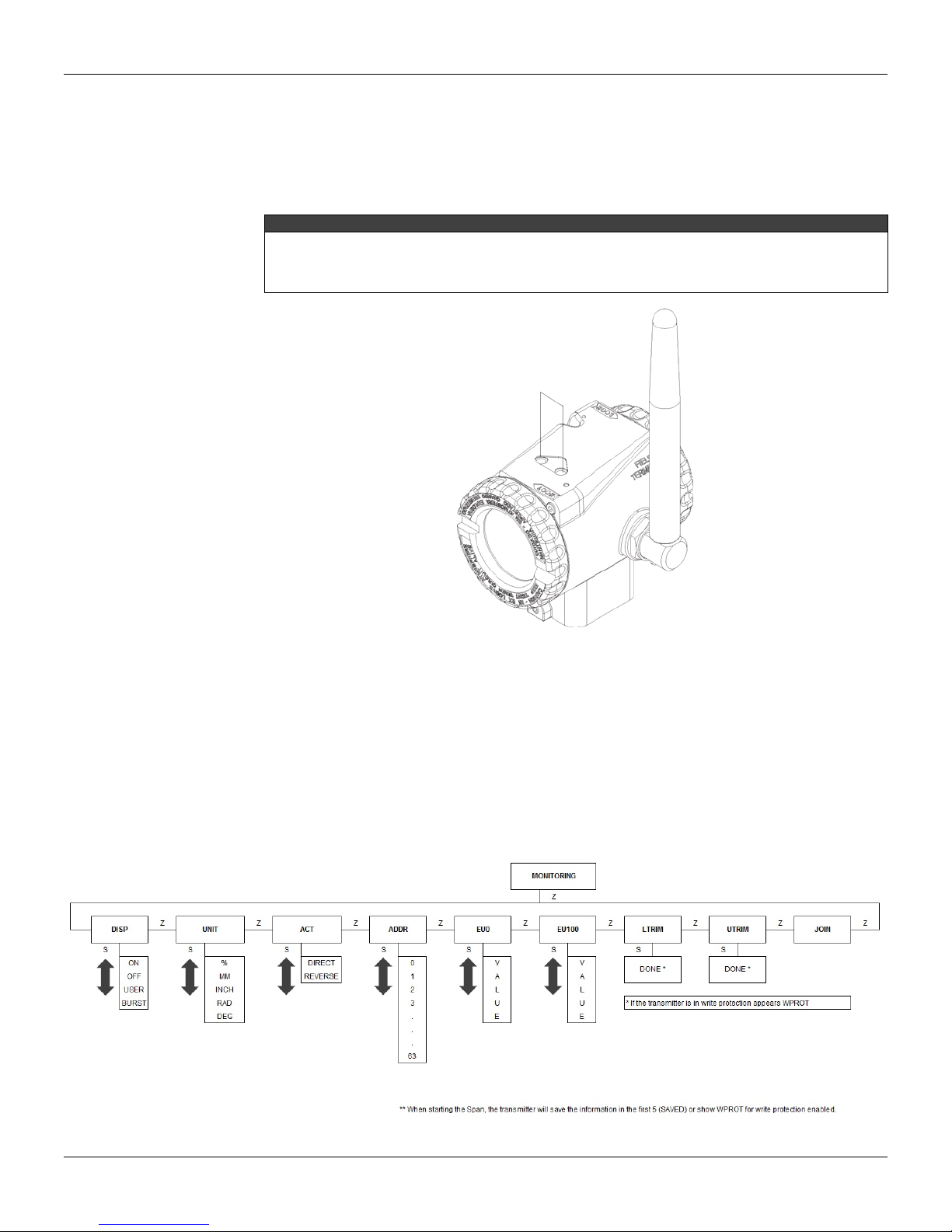
The holes are marked with Z (Zero) and S (Span) and from now on will be designated simply by (Z) and
(S), respectively. See the following figure:
NOTE
For configuration via local adjustment the following actions are necessary:
The write protection jumper must be disabled;
The local adjustment jumper must be enabled.
See on Figure 1.11 the location of Local Adjustment and Write Protection jumpers on the main board.
Figure 2.2 – Local Adjusment
Browsing the functions and their branches works as follows:
Inserting the handle of the magnetic tool in (Z), the device passes from the norma l measurement
state to the configuration state. The position transmitter software automatically starts to display
the available functions in a cyclic routine.
Apply the magnetic tool in (Z) to navigate through all available configuration options;
Once the display shows the desired option, change the magnetic tool to (S) to select and
navigate within the branch of the selected option. Removing the magnetic tool will allow the
device to save the configurations (in case of changing).
The options available for TP400W local adjustment are:
Figure 2.3 – Local adjustment - Options
2.3
Page 28

TP400 WirelessHARTTM - Operation and Maintenance Instruction Manual
The DISP option changes the configuration of display mode. There are four modes supported:
OFF: display always turned off
ON: display always turned on
USER: display normally off but activated when user inserts the magnetic key (S)
BRST: display normally off but activated when device sends a burst command.
UNIT: Engineering unit or percentage;
ACT: Direct or reverse action;
ADDR: Address 0 up to 63;
EU0: 0% corresponding to lower value;
EU100: 100% corresponding to upper value;
LTRIM: Lower position Trim (set with the actuator or mechanism in the lower position);
UTRIM: Upper position Trim (adjust with the actuator or mechanism in the upper position);
The ADDR and JOIN options are read-only and are used to identify the configuration address by
maintenance port and the device status on the WirelessHART
Write Protection
The write protection function can be activated by two ways: hardware (switch on main board) and
software. The writing of any parameter only will be able if both protections are disabled.
Another way to protect the writing, but partially, is using the Lock Device option (WirelessHART).
This option is used in WirelessHART devices to block the writing for only one configuration master,
Communication Port or Gateway. With this function user avoids configuration conflicts when acting by
one of the configurators in dangerous situations.
The types of locking are:
Unlocked: both configurators have write permission.
Temporarily Locked: only the configurator that locked the device has write permission.
However, after restarting the device its state returns to Unlocked.
Permanently Locked: only the configurator that locked the device has write permission, and its
state remains even after restarting the device.
All locked: no configurator has write permission until the device is unlocked by the same
configurator that locked it.
ATTENTION
The use of this function is intended only for special occasions, which the security parameter writing is critical and fast.
After writing, the configurator must return the device to the Unlocked mode.
TM
network, respectively.
2.4
Page 29
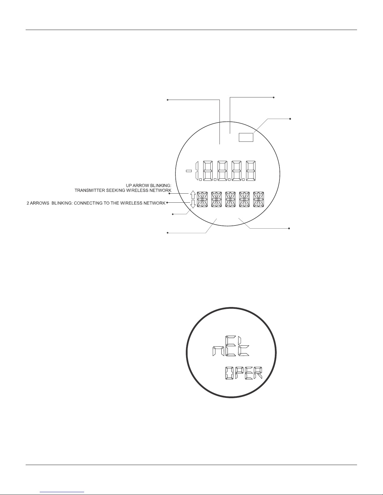
Functional Description - Display (LCD)
The local indicator is able to display three variables, which are user-selected. When multiples variables
are chosen, the display will alternate between both with an interval of 3 seconds.
The liquid crystal display includes a field with 4 ½ numeric digits, a field w ith 5 alphanumeric digits and
an information field, as shown on Figure 2.4.
INDICATES THAT TOTALIZATION
IS ENABLED
F (t)
ACK
MD
TRANSMITTER IN
BURST MODE
TRANSMITTER IS OPERATING
ON WIRELESS NETWORK
Operation
DOWN ARROW: F AILED T O CONNECT T O THE WIRELESS NETWORK
BLINKING WHEN SENDING EVENT TO THE
WIRELESS NETWORK
Monitoring
During normal operation, the TP400 WirelessHART
indication alternates between the three variables (LCD_1, LCD_2, LCD_3) as configured by the user.
The display indicates engineering units, values and parameters simultaneously with most status
indicators.
SP PV
Figure 2.4 – Display
PRIMARY VARIABLE
INDICATION
TM
is in the monitoring mode. In this mode,
The monitoring mode is interruped when the user applies the complete local adjustment.
The TP400 WirelessHART
Section 3 – Maintenance.
Figure 2.5 – Typical Display in Monitoring Mode
TM
display may also exhibit messages and errors. For a complete list, see
2.5
Page 30

TP400 WirelessHARTTM - Operation and Maintenance Instruction Manual
2.6
Page 31
Section 3
MAINTENANCE
General
Diagnostic with Display
Disassembly Procedure
The network position transmitter TP400 WirelessHARTTM are extensively tested and inspected before
being sent to the user.
All maintenance service should be done by a qualified person and the exchange of components
(supplied by Smar) should only be performed by people certified to do so.
The display can show failure messages in alphanumeric segment. When these messages are shown,
the position transmitter automatically goes to a safe state. These messages are shown in Table 3.1.
DIAGNOSTIC MESSAGES PROBABLE SOURCE OF TROUBLE
FAIL RADIO Indicates problem in the radio.
LOW BATT Indicates low battery level.
FAIL BATT Indicates critical battery level.
This type of operation should be done in a safe area and the position transmitter turned off.
The board has CMOS components which may be damaged by electrostatic discharges. Observe correct
procedures for handling CMOS components. It is also recommended to store the circuit boards in electrostaticproof cases.
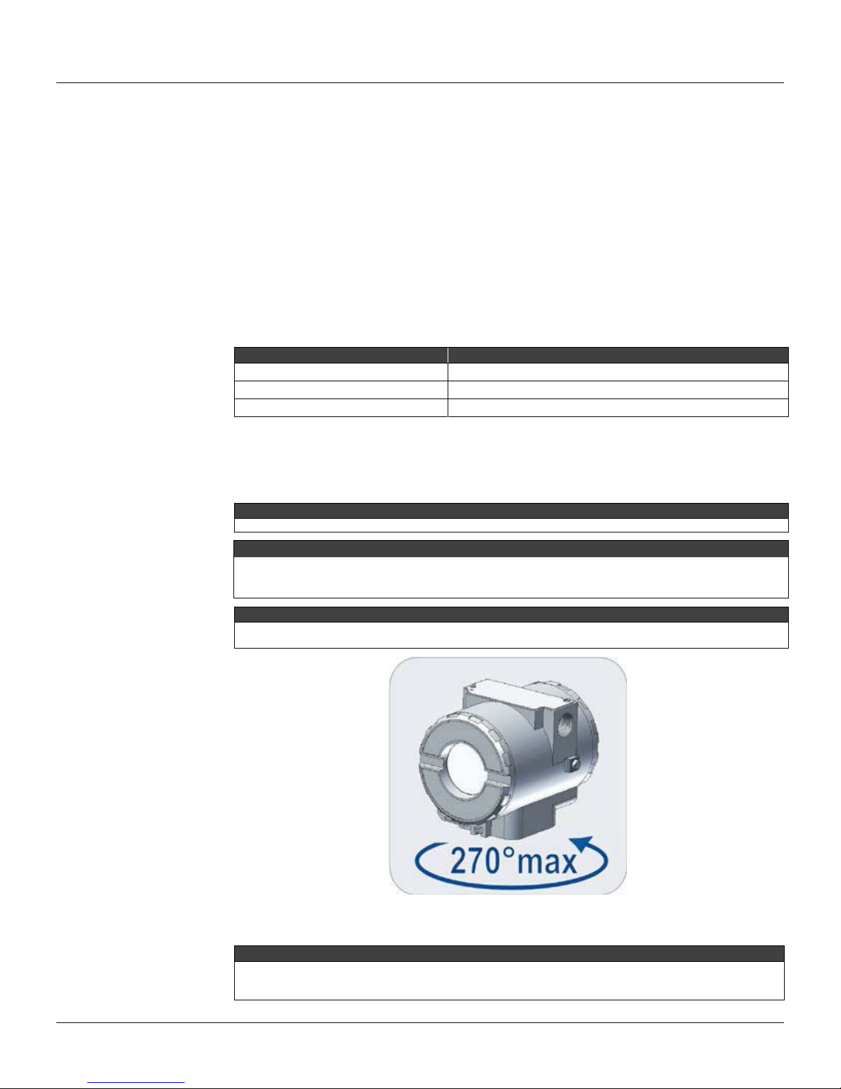
To avoid damage do not rotate the electronic housing more than 270º starting from the fully threaded. See the
following figure.
Tabele 3.1 – Diagnostic with Display
ATTENTION
WARNING
IMPORTANT
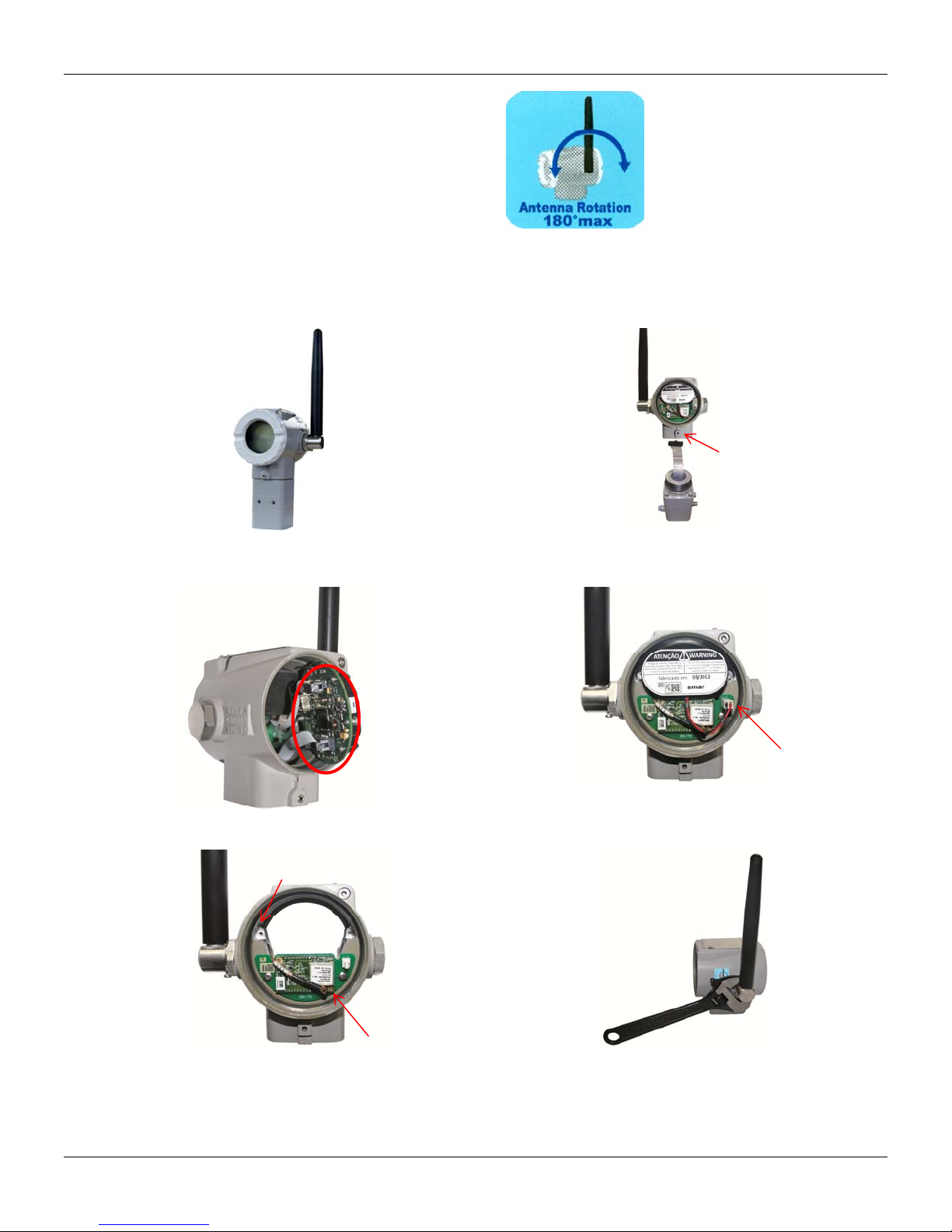
To avoid device damage, do not rotate the antenna below the 180° imaginary line relative to the device base. If
there is the need to rotate the antenna, loosen the locking screw and the move it just above this line. See the
following figure. For more details see the topic "Antenna Rotation" in section 1.
Figure 3.1 – housing safety rotation
IMPORTANT
3.1
Page 32
TP400 WirelessHARTTM - Instruction, Operation and Maintenance Manual
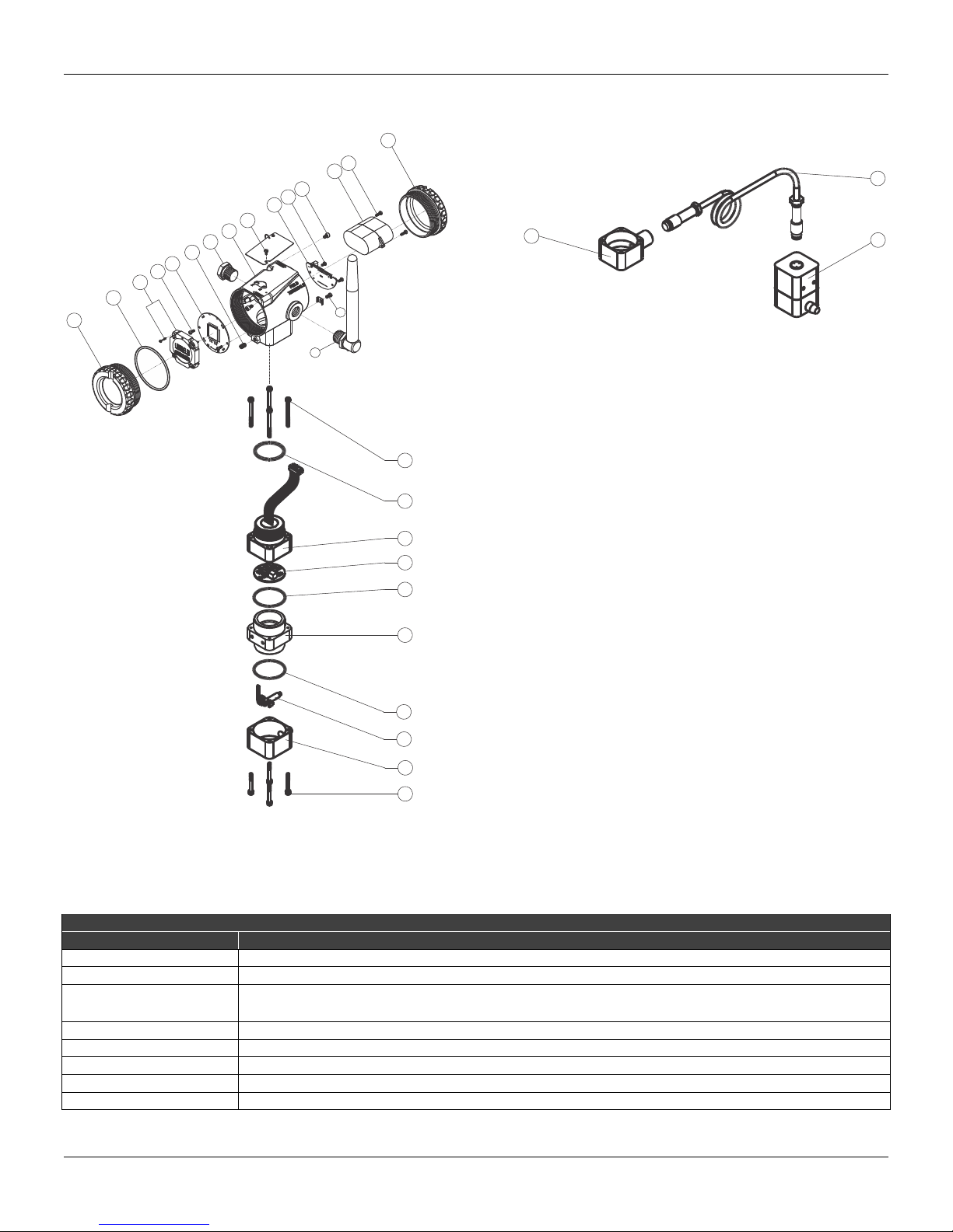
Here is the disassembly procedure of TP400. Figure 3.3 indicates the position of the components
mentioned in this description
a) Open the frontal (1) and rear covers (15);
Figure 3.2 – Antena safety rotation
b) Open the bottom cover (20), loosening the housing
fixation screw (6);
c) Remove the main board (5) on the front housing (8),
disconnecting the radio board (10);
e) Disconnect the antenna cable from the radio board, as
shown in the picture. Unscrew the radio board from
housing;
3.2
d) Disconnect Battery Module (13) from radio board at the
point indicated and unscrew it from the housing;
f) Loosen the antenna (17) with the aid of a wrench. Use
the wrench in the way is being shown in the picture,
always beneath the antenna;
Page 33
Assembly Procedure
This type of operation should be done in a safe area and with the position transmitter turned off.
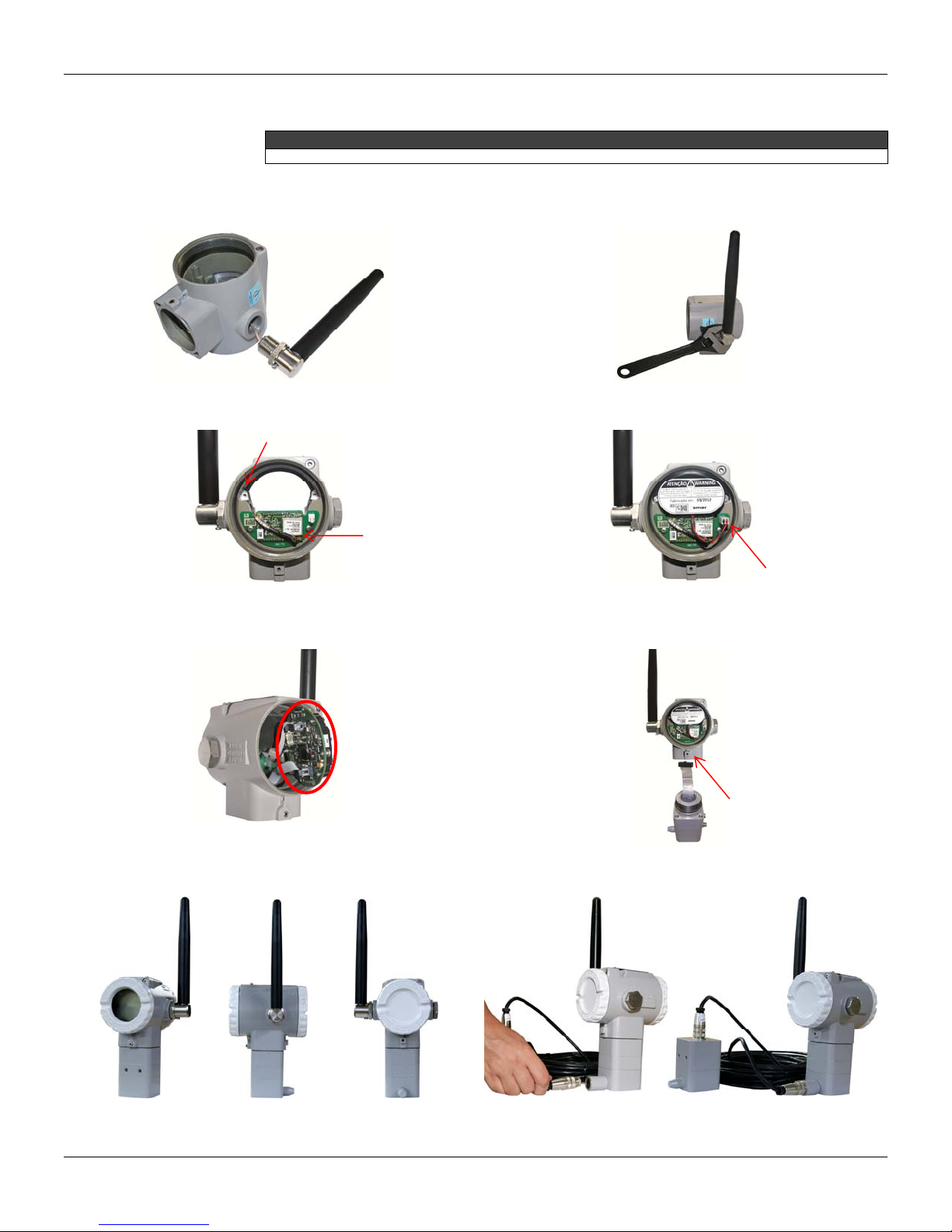
Here is the assembly procedure of TP400. Figure 3.3 indicates the position of the components
mentioned in this description.
Maintenance
ATTENTION
a) First, make the antenna assembly (17) on the housing
side (8) indicated by "FIELD TERMINALS";
c) Screw the radio board (10) on the back of the housing.
Pass the antenna cable through the hole indicated in the
picture and connect it to the radio board as shown in the
picture;
b) T ighten the antenna with a wrench. Use the wrench as
shown in the picture, always beneath the antenna. At th e
end, keep the antenna in a vertical position;
d) Screw Battery Module (13) and connect it to the radio
board at the point indicated;
e) Place the main board (5) on the front of the housing and
connect the radio cable to it. After connection, screw the
board to the housing;
g) End threading the front (1) and rear (15) covers; h) Mounting with Remote Sensor (optional).
f) Fit the cover (20) at the bottom of the housing, locking it
with the fixing screw (6);
3.3
Page 34

TP400 WirelessHARTTM - Instruction, Operation and Maintenance Manual
Troubleshooting
1) Device does not connect to the WirelessHART network.
POSSIBLE CAUSES:
The device is turned off;
The Network Manager/Gateway is turned off;
The device is far from the Network Manager/Gateway or other device connected to it;
Network ID and Join Key are not configured correctly;
The antenna is not connected to the Network Manager/Gateway or to the device;
There is an Access Control List in the Network Manager/Gateway and the device is not on this
list ;
Maximum number of devices configured in Network Manager/Gateway has been reached.
2) Device co nnects and disconnects to the WirelessHART network.
POSSIBLE CAUSES:
Low battery or bad contact in the powering causing a device restarting;
The connectivity related to the neighbors is unstable (moving obstacles or distance in the limit);
3) Devices in the operation range but with low communication stability.
POSSIBLE CAUSE:
Interference. Approximate the devices to get a better stability.
3.4
Page 35
Exploded view
®
7
6
5
4
3
2
1
Maintenance
15
14
13
12
11
10
9
8
16
17
18
19
27
28
29
20
21
22
23
22
24
25
26
Figure 3.3 – Exploded view
Accessories and Spare Parts
ACCESSORIES
ORDERING CODE DESCRIPTION
SD-1
Palm*
HPC401*
HPC401 Plus *
CONF401*
HI321*
400-1176
400-1177
* For upgrades of devices and software HPC401 or CONF401 visit: http://www.smarresearch.com .
Magnetic tool for local adjustment.
Palm Handheld, 16 Mbytes, including installation software and startup of HPC401.
HART Interface - (HPC401 Plus) for Palm, including configuration package for Smar transmitters and
generic transmitters.
HART
Interface.
PC-based Smar configurator.
HART Interface for CONF401.
Teflon guide for linear magnet.
Teflon guide for rotary magnet.
3.5
Page 36

TP400 WirelessHARTTM - Instruction, Operation and Maintenance Manual
LISTA DE SOBRESSALENTES
DESCRIÇÃO DAS PARTES POSIÇÃO CÓDIGO
FRONT COVER (WITH WINDOW FOR INDICATION) 01 400-0822
COVER O-RING (NOTE 3)
DISPLAY (WITH SCREWS) 03 400-0828
MAIN BOARD FIXATION SCREW
MAIN BOARD 05 400-1274 A
COVER LOCKING SCREW 06 400-1121
M20 x 1,5 HEXAGONAL PLUG 07 400-0810
HOUSING 400W SERIES (NOTE 2)
PLATE FIXATION SCREW 09 204-0116
RADIO BOARD 10 400-1211
RADIO BOARD FIXATION SCREW 11 400-1212
COVER LOCKING SCREW 12 204-0120
BATTERY MODULE 13 400-1209
BATTERY MODULE FIXATION SCREW 14 400-1210
REAR COVER (WITHOUT WINDOW FOR INDICATION) 15 400-1208
EXTERNAL GROUND SCREW
WIRELESS ANTENNA 17 400-1214
CONNECTION COVER SCREW 18 400-0883
O-RING, Neck (NOTE 3)
CONNECTION COVER
ANALOG BOARD 21 400-1275
UNION BLOCK O-RING (NOTE 3)
UNION BLOCK
POSITION SENSOR BRACKET + POSITION SENSOR SENSOR + FLAT CABLE 24 400-0927
POSITION SENSOR COVER
POSITION SENSOR COVER BOLT 26 400-0092
REMOTE POSITION SENSOR COVER SET (NOTE 4)
CABLE SET + CONNECTOR
REMOTE EXTENSION SET
TRANSDUCER SET - 400-1277
MOUNTING BRACKET
MAGNETS
CARBON STEEL
316 STAINLESS STEEL
ALUMINUM
316 STAINLESS STEEL
HOUSING IN ALUMINUM
HOUSING IN 316 STAINLESS STEEL
ALUMINUM
316 STAINLESS STEEL
ALUMINUM
316 STAINLESS STEEL (H1)
ALUMINUM
316 STAINLESS STEEL
ALUMINUM
316 STAINLESS STEEL
5 m
10 m
15 m
20 m
ALUMINUM
316 STAINLESS STEEL
CARBON STEEL FOR 2”PIPE
316 STAINLESS STEEL
LINEAR MAGNET UP TO 30 MM
LINEAR MAGNET UP TO 50 MM
LINEAR MAGNET UP TO 100 MM
ROTARY MAGNET
02 204-0122 B
04
08
16
19 204-0113
20
22 400-0915
23
25
27
28
29
-
-
400-0905
400-0832
400-1205
400-1206
400-0904
400-0826
400-0910
400-0911
400-1276
400-1276
400-0928
400-0929
400-0932
400-0933
400-0857
400-0858
400-0859
400-0860
400-0934
400-0935
400-0339
400-0340
400-0748
400-0035
400-0036
400-0037
CATEGORIA
(NOTA1)
1) For category A it is recommended to keep in stock one set for 25 installed parts, and for category B one set for 50 installed parts.
2) It includes screws (cover locking and grounding) and identification plate without certification.
3) O-Rings are packaged in packs of 12 units.
4) Includes cover, Position Sensor with flat cable and connector for cable extension.
NOTES
3.6
Page 37

Returning Materials
Maintenance
Should it become necessary to return the position transmitter and/or configurator to SMAR, simply
contact your local agent or SMAR office, informing the defective device's serial number, and return it to
our factory.
In order to expedite analysis and solution of the problem, the defective item should be returned with a
description of the failure observed, with as much details as possible. Other information concerning to the
instrument operation, such as service and process conditions, is also helpful. For this, fill out the SRF
(Service Request Form). The SRF is available on Appendix A.
Devices returned or to be revised outside the guarantee term should be accompanied by a purchase
order or a quote request.
ATTENTION
The device must have its Battery Module disconnected before being sent for safety and shipping
standards. To do this, first turn it off by front switch (Figure 1.11). Disconnect the Battery Module and
radio board, located at the rear of the device.
3.7
Page 38

TP400 WirelessHARTTM - Instruction, Operation and Maintenance Manual
3.8
Page 39

Section 4
®
TM
Travel
Battery Module
Communication Protocol
Output Signal
Measurement Type
Zero and Span Adjustment
Indicator
Temperature Limits
Configuration
TECHNICAL CHARACTERISTICS
FUNCTIONAL SPECIFICATIONS
Linear Motion: 3 - 100 mm. (For measurement beyond 100 mm consult the BFY-CL catalog at
www.smar.com).
Rotary Motion: 30° - 120° Rotation Angle.
The module consists of 2 primary lithium batteries (Li - SOCl2 ) of 3.6 V, totaling 7.2 V.
Duration
Burst Mode at 8 seconds, @25°C, network with at least 3 neighbors devices: 3 years.
Note: The Battery Module used in the repeaters must be provided exclusively by Smar (Battery
Module - Code 400-1209).
HART
Version 7 protocol, with TP400 WirelessHART
®
A HART
transmitter.
HART
transmitter specific review must be managed according to the TP400 WirelessHART
®
is a trademark of HART Communication Foundation.
Digital output via 2.4 GHz radio frequency, according to HCF_SPEC-65 Rev. 1.0.
Position for linear and rotary displacement.
Jumper of local adjustment with two positions: Able and Disable.
Rotary CLD with 4½ - numerical digits and 5 alphanumerical characters.
Function and Status Indication.
Ambient: -40 to 85ºC (-40 to 185ºF).
Storage: -40 to 90ºC (-40 to 194ºF).
Digital Display: -10 to 75ºC ( 14 to 167ºF) in operation;
-40 to 85ºC (-40 to 185ºF) without damage.
Remote Sensor:
-40 to 105°C (-40 to 221°F).
Remotely with external programmer via WirelessHART
Locally via programmer with wired maintenance port.
command set.
TM
network.
TM
Humidity Limits
Failure Alarms
(Diagnostics)
Wireless Certification
(pending)
Update Time
Turn-on Time
Reading of the Position
Position Sensor
Accuracy
Resolution
Repeatability
Hysteresis
Temperature Effect
Electromagnetic
Interference Effect
Electrical Connection
Material of Construction
0 to 100% RH (Non-condensable Relative Humidity).
Detailed diagnostics via HART® communicator and display LCD.
ANATEL (National Telecommunications Agency).
2 seconds.
Performs within specifications in less than 7 seconds after power is applied to the transmitter.
Direct or reverse.
Non-contact Hall effect sensor.
Available in the remote mounting version (optional; consult the Smar on applicable harzardous
certifications).
PERFORMANCE SPECIFICATIONS
≤ 0.2% F. S. the effects of linearity, hysteresis and repeatability are included.
(NOTE: For more precise linear measurements use the linearization process. Refer to the Linearization chapter on
the Instructions Manual.)
≤ 0.1 % F.S.
≤ 0.5 % F.S.
≤ 0.2 % F.S.
± 0.8% / 20ºC F.S.
Designed to comply with European Directive EMC 2004/108/EC.
PHYSICAL SPECIFICATIONS
M20 X 1.5 (default to antenna wireless equipment).
Injected low copper Aluminum with polyester painting or Stainless Steel housing, with Buna N
O-Rings on cover (NEMA 4X, IP66).
4.1
Page 40
TP400 WirelessHARTTM - Operation, Maintenance and Instructions Manual
PHYSICAL SPECIFICATIONS
Mounting Brackets
Identification Plate
In SAE 1020 Carbon Steel with electrostatic polyester paint or Stainless Steel.
Including accessories (bolts, nuts, washers and U-clamp) in Carbon Steel or Stainless Steel.
Stainless Steel plate with label in special plastic.
TP400
1.8 kg in Aluminum;
3.6 kg in Stainless Steel.
Remote Position Sensor
Approximate Weight
0.58 kg in Aluminum;
1.5 kg in Stainless Steel.
Cable and Connector
Add 0.05 kg for the Remote Sensor connector and 0.045 kg/m for each meter of the Remote
Sensor extension cable.
Antenna omnidirectional 2.4 GHz.
Electronic Circuit
Coaxial cable to connect the antenna with the radio board.
Battery pack with 2 units Type 'C'.
OPERATION PROTECTION SPECIFICATIONS
Counter Operation
Protection Configuration
Certification
Historical of configuration change.
Write protection via hardware and software.
Intrinsic safety (pending) and weather proof.
HUMAN MACHINE INTERFACE (HMI) SPECIFICATIONS
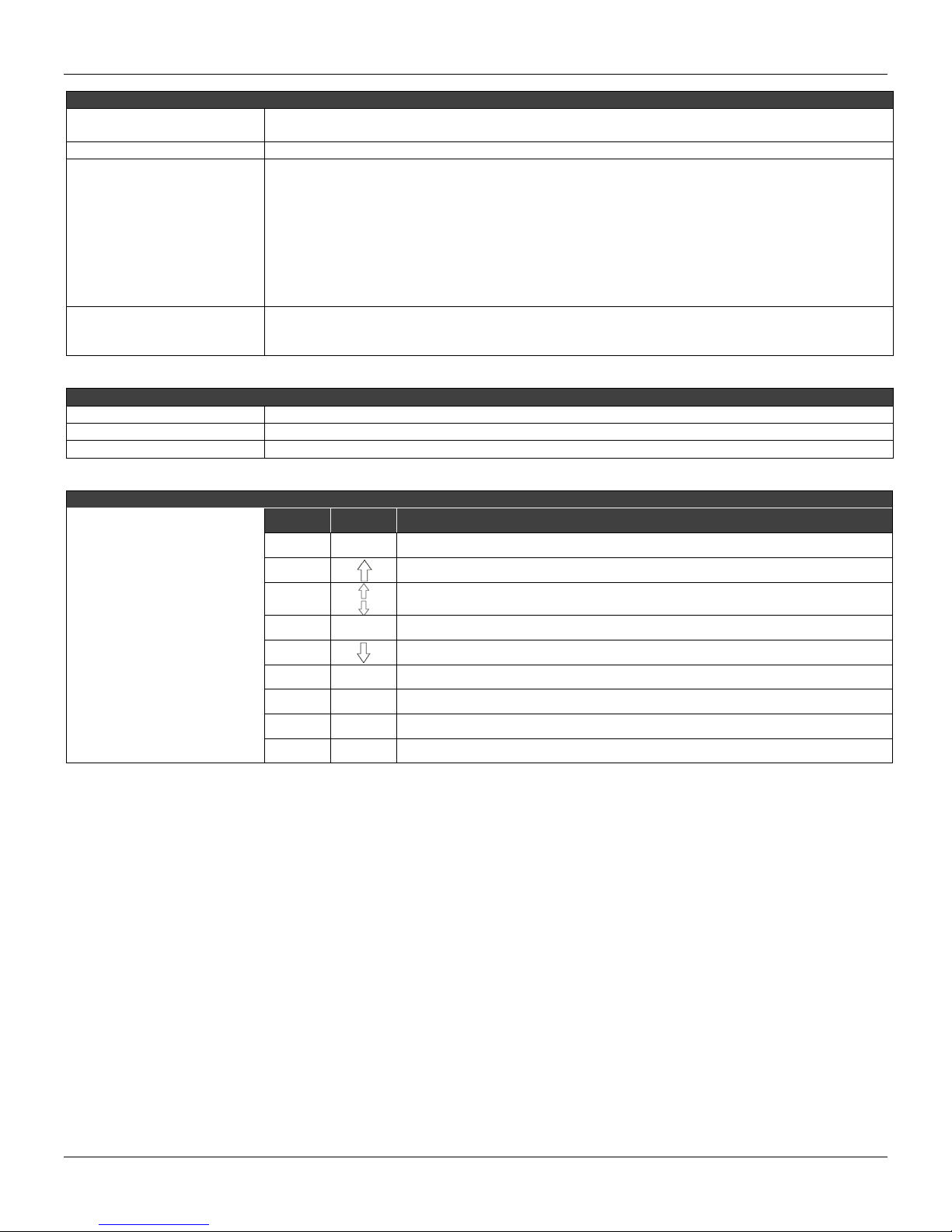
ITEM ICON DEFINITION
1 PV Indication of the primary variable
Display LCD
Status
2
3
4 MD Transmitter operating on a wireless network
5
Blinking when the transmitter is seeking wireless network
Flashing when connecting to the wireless network
Failed to connect to the wireless network
6 ACK Transmitter in burst mode
7 F(t) Lights when sending command in burst mode
8 SP Lights when an event is sent by the device
9 F(x) When the points table for linearization is enabled
4.2
Page 41
Technical Characteristics
TM
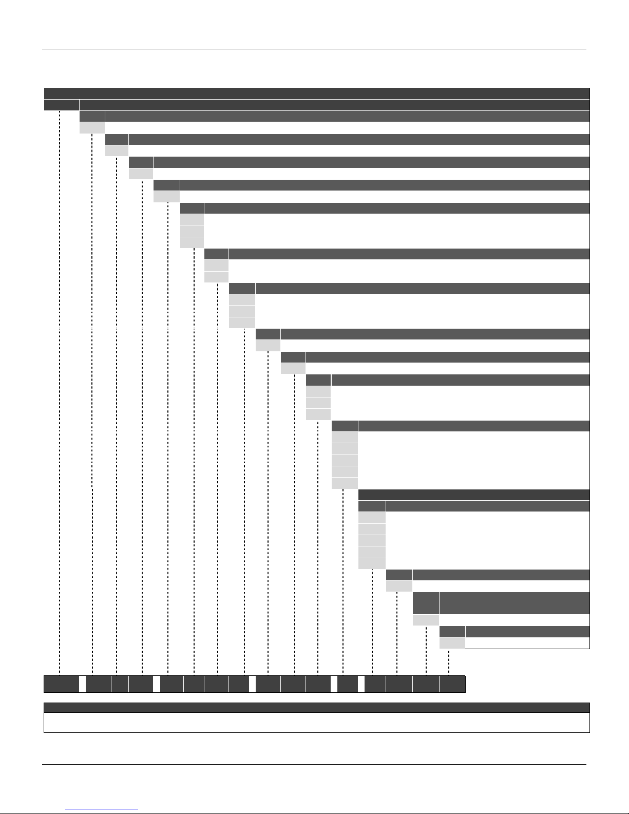
Ordering Code
MODEL
TP400 POSITION TRANSMITTER
COD Communication Protocol
WirelessHART
W
COD Security Option
0
Standard (for use in measurement and control)
COD Local Indicator
1
COD Electrical Connection
COD Mounting Bracket
COD Housing
COD Painting
COD Certification Type
COD Certifying Body
COD TAG Plate
COD Type of Actuator
COD Special Features
W1
COD Manufacture Standard
S0
With digital indicator
M20 X 1.5 (also standard antenna for wireless device)
A
Without Bracket
0
Carbon Steel Brackets
1
Stainless Steel Brackets
2
Aluminum (IP/TYPE)
A
316 Stainless Steel - CF8M (ASTM - A351) (IP/TYPE)
I
Gray Munsell N 6.5 Polyester
0
Without Painting
8
User specification
Z
Without Certification
N
Without
0
With TAG, when specified
0
Blank
1
User specification
2
0
1
5
7
A
Without magnet
Rotary
Linear up to 50 mm
Linear up to 100 mm
Linear up to 30 mm
SPECIAL OPTIONS (1)
COD Sensor Mounting (2)
Full Mounting
R0
Remote sensor - 5 m cable
R1
Remote sensor - 10 m cable
R2
Remote sensor - 15 m cable
R3
Remote sensor - 20 me cable
R4
User specification
ZZ
Certification for
COD
Telecommunications
ANATEL
SMAR
TP400 - W 0 1 - A 1 A 0 - N 0 0 - 1 . * * * *
1) Leave it blank for no optional item.
2) Consult Smar for applications in hazardous areas.
TYPICAL MODEL NUMBER
NOTE
4.3
Page 42

TP400 WirelessHARTTM - Operation, Maintenance and Instructions Manual
4.4
Page 43

Appendix A
Model: TP400 ( ) Firmware Version: ______________________
Serial
Number:
TAG: _________________________________________________________________________________________________
Remote
Position
Sensor?
Action: Rotary ( ) Linear ( )
Travel: 30 mm ( ) 50 mm ( ) 100 mm ( ) Other: __________________ mm
Configuration: Magnetic Tool ( ) Palm ( ) PC ( ) Software: __________________ Version: ___________
Type: Valve + Atuador ( ) Other: ____________________________________________________________
Size: _______________________________________________________________________________________________
Travel: _______________________________________________________________________________________________
Manufacturer: _______________________________________________________________________________________________
________________________________________________
Yes ( ) No ( )
SRF – Service Request Form
GENERAL DATA
INSTALLATION DATA
TP Position Transmitter
Model: _______________________________________________________________________________________________
PROCESS DATA
Hazardous Área
Classification
Interference
Types
Non-Classified ( ) Chemical ( ) Explosive ( ) Other: ________________________________
Vibration ( ) Temperature ( ) Electromagnetic ( ) Others: _______________________________
SITUATION DESCRIPTION
______________________________________________________________________________________________________________
______________________________________________________________________________________________________________
______________________________________________________________________________________________________________
______________________________________________________________________________________________________________
SERVICE SUGGESTION
Adjustment ( ) Cleaning ( ) Preventive Maintenance ( ) Update / Up-grade ( )
Other: _________________________________________________________________________________________________________
USER INFORMATION
Company: _____________________________________________________________________________________________________
Contact: ______________________________________________________________________________________________________
Title: _________________________________________________________________________________________________________
Section: ______________________________________________________________________________________________________
Phone: _________ _________________________ _________ _________________________ Extension: ____________________
E-mail: ________________________________________________________________________ Date: _______/ _______/ _________
Further information about address and contacts can be found on www.smar.com/contactus.asp.
For warranty or non-warranty repair, please contact your representative.
A.1
Page 44

TP400 WirelessHARTTM – Operation and Maintenance Instruction Manual
Returning Materials
Should it become necessary to return the transmitter and/or configurator to SMAR, simply contact
our office, informing the defective instrument serial number, and return it to our factory.
In order to speed up analysis and solution of the problem, the defective item should be re turned with
a description of the failure observed, with as much details a s possible. Other inform ation concernin g
the instrument operation, such as service and process conditions, is also helpful.
Instruments returned or to be revised outside the guarantee term should be accompanied by a
purchase order or a quote request.
A.2
Page 45

Appendix B
BATTERY SAFETY DATASHEET
Section 1 – Identification
Manufacturer: Tadiran
Model: TL-5920
US office address: 2001 Marcus Avenue, Suite 125E, Lake Success, NY 11040
Emergency Telephone: 1-800-424-9300
Information Telephone: 1-516-621-4980
Section 2 – Composition
Ingredients %
Lithium Metal (Li) <5%
Thionyl Chloride (SOCl2) <47%
Carbon (C) <6%
Aluminum Chloride (AlCl3) <5%
Lithium Chloride (LiCl) <2%
Glass <1%
PVC <1%
PTFE <1%
Steel, nickel and inherent components balance
Section 3 – Hazard Identification
The batteries described herein are hermetically sealed and are not hazar dous when used accordin g
to the manufacturer's recommendations.
Batteries should not be exposed to short-circuit, recharged, punc hed, burn ed, crushed, immersed in
water, forced to discharge or placed in temperatures above the range specified for the product. In
these cases there is a risk of fire and explosion.
Section 4 – First aid
In case of rupture, explosion or leakage, remove personnel from the contaminated area and
ventilate it to release smoke, corrosive gases and odor. Seek medical help immediately.
Eyes - flush with plenty of water for at least 15 minutes (remove contact lenses if possible) and then
seek medical attention.
Skin - Remove contaminated clothing and flush affected ski n with plenty of water for 15 minutes and
then seek medical attention.
Inhalation - look for an area with fresh air, rest, use artificial respiration, if necessary, and seek
medical attention.
Ingestion - rinse your mouth, do NOT induce vomiting, drink lots of water, and then se ek medical
attention.
Section 5 – Fire fighting
If the batteries are directly involved in fire DO NOT USE: WATER, SAND, CO2 and DRY
CHEMICAL POWDER EXTINGUISHERS.
If the batteries are in a location adjacent to the fire, it can b e combated ac cordi ng to the combusti ble
material (paper or plastic, for example). In this case, the use of large quantities of cold water would
be an effective way to combat.
To firefighting use equipment and protective clothing that prevent contact with battery solution. The
fire must be fought at a safe distance and after evacuation of the area.
B.1
Page 46

TP400 WirelessHARTTM – Operation and Maintenance Instruction Manual
Batteries may explode when exposed to: excessive heat (above 150 °C), recharged, discharged
below 0V, punched and crushed. Hydrogen Chloride (HCl) and sulfur dioxide (SO
during thermal decomposition of Cl
.
2
Section 6 – Leakage
The material contained in the batteries will leak only if exposed to abusive conditions.
On the occasion of leakage: contain the leakage if us ing protective clothing and ventilate the area
well. Cover with Sodium Carbonate (Na2CO3) and keep away from water, rain or snow. Put in a
secure container and pour into proper trash, according to local regulatory standards.
Section 7 – Handling and storage
Never attempt to disassemble or modify the batteries as this may result in accident.
HANDLING – do not short-circuit the terminals or expose to temperatures above the range specified
for the battery, overload, force discharge or thrown in fire. Do not punch, crush or immerse in water.
STORAGE – preferably store in an environment below 30 °C, dry and ventilated subject to less
variation in temperature.
Do not store the batteries near heating equipment, nor expose to dir ect sunlight for long periods.
Elevated temperatures may result in shortened batteries life and degrade their performance.
Do not store batteries in high humidity environment for long periods.
The batteries should not be recharged. High pressures can cause deformities and release of
chemicals from the battery.
Ecological Information: When properly used or discarded, the batteries pose no danger to the
environment. The batteries do not contain mercury, cadmium or lead. Do not let internal
components exposed to the marine environment.
Disposal: Absolutely not incinerate batteries. Dispose of batteries according to local regulations.
Transportation: Batteries are considered "Dangerous Goods" when transported in or out of
equipment.
For additional information, see the manufacturer's website
http://www.tadiranbat.com/index.php/shipping-and-information
) can be formed
2
B.2
 Loading...