

Page 1
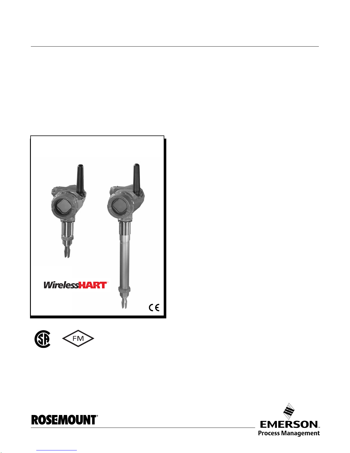
Reference Manual
2160***E
2160***S
00809-0100-4160, Rev AB
March 2010
Rosemount 2160 WirelessHART
Vibrating Fork Liquid Level Switch
™
www.rosemount.com
Page 2

Page 3
Reference Manual
NOTICE
00809-0100-4160, Rev AB
March 2010
Rosemount 2160
Rosemount 2160 WirelessHART
Vibrating Fork Liquid Level Switch
Rosemount 2160 Hardware Revision 1
®
Device Revision 1
HART
Field Communicator Field Device Dev v1, DD v2
Read this manual before working with the product. For personal and system safety, and for
optimum product performance, make sure you thoroughly understand the contents before
installing, using, or maintaining this product.
For technical assistance, contacts are listed below:
Customer Central
Technical support, quoting, and order-related questions.
United States: 1 800 999 9307 (7:00 am to 7:00 pm CST)
Asia Pacific: 65 777 8211
Europe/ Middle East/ Africa: 49 (8153) 9390
North American Response Center
Equipment service needs.
1 800 654 7768 (24 hours—includes Canada)
Outside of these areas, contact your local Emerson Process Management representative.
The products described in this document are NOT designed for nuclear-qualified
applications.
Using non-nuclear qualified products in applications that require nuclear-qualified hardware
or products may cause inaccurate readings.
For information on Rosemount nuclear-qualified products, contact an Emerson Process
Management Sales Representative.
Replacement equipment or spare parts not approved by Emerson for use as spare
parts could reduce the capabilities of the 2160, and may render the instrument
dangerous.
• Use spare parts supplied or sold by Emerson
www.rosemount.com
Page 4

Rosemount 2160
NOTICE
Reference Manual
00809-0100-4160, Rev AB
March 2010
Failure to follow these installation guidelines could result in death or serious injury
• The Rosemount 2160 is a wireless liquid level switch. It must be installed, connected,
commissioned, operated, and maintained by suitably qualified personnel only , observing
any national and local requirements that may apply
• Use the equipment only as specified in this manual. Failure to do so may impair the
protection provided by the equipment
Explosions could result in death or serious injury
• Installation of the 2160 in a hazardous environment must be in accordance with the
appropriate local, national, and international standards, codes, and practices.
Please review the approvals section of the 2160 Reference Manual for any restrictions
associated with an installation
• Before connecting a Field Communicator in an explosive atmosphere, ensure the
installation is in accordance with intrinsically safe or non-incendive field wiring practices
• Verify that the operating atmosphere of the level switch is consistent with the
appropriate hazardous locations certifications
External Surface may be hot
• Care must be taken to avoid possible burns
Process leaks could result in death or serious injury
• Install and tighten process connectors before applying pressure
• Do not attempt to loosen or remove process connectors while the 2160 is in service
Electrical shock could cause death or serious injury
• If the liquid level switch is installed in a high voltage environment and a fault condition or
installation error occurs, high voltage may be present on leads and terminals
• Use extreme caution when making contact with the leads and terminals
• Make sure that power to the 2160 is off while making connections
Operation is subject to the following two conditions: (1) This device may not cause
harmful interference, and (2) this device must accept any interference received,
including interference that may cause undesired operation.
II
Shipping considerations for wireless products:
The unit was shipped to you without the power module installed. Please remove the power
module prior to shipping.
Each power module contains two “C” size primary lithium batteries. These batteries are
regulated in transportation by the U. S. Department of Transportation, and are also covered
by IATA (International Air Transport Association), ICAO (International Civil Aviation
Organization), and ARD (European Ground Transportation of Dangerous Goods). It is the
responsibility of the shipper to ensure compliance with these or any other local requirements.
Please consult current regulations and requirements before shipping.
The power module with the wireless unit contains two “C” size primary lithium/thionyl chloride
batteries. Each battery contains approximately 2.5 grams of lithium, for a total of 5 grams in each
pack. Under normal conditions, the battery materials are self-contained and are not reactive as
long as the batteries and the pack integrity are maintained. Care should be taken to prevent
thermal, electrical or mechanical damage. Contacts should be protected to prevent premature
discharge.
Battery hazards remain when cells are discharged.
Batteries should be stored in a clean and dry area. For maximum battery life, storage temperature
should not exceed 86 °F (30 °C).
Page 5

Reference Manual
00809-0100-4160, Rev AB
March 2010
Rosemount 2160
Table of Contents
SECTION 1
Overview
SECTION 2
Configuration
Safety Messages. . . . . . . . . . . . . . . . . . . . . . . . . . . . . . . . . . . . . . . . . . . . .1-1
Warnings. . . . . . . . . . . . . . . . . . . . . . . . . . . . . . . . . . . . . . . . . . . . . . . .1-1
Using This Manual. . . . . . . . . . . . . . . . . . . . . . . . . . . . . . . . . . . . . . . . . . . .1-2
Definitions And Abbreviations . . . . . . . . . . . . . . . . . . . . . . . . . . . . . . . . . . .1-2
Models Covered. . . . . . . . . . . . . . . . . . . . . . . . . . . . . . . . . . . . . . . . . . . . . . 1-2
About the 2160 . . . . . . . . . . . . . . . . . . . . . . . . . . . . . . . . . . . . . . . . . . . . . . 1-3
Switch Overview . . . . . . . . . . . . . . . . . . . . . . . . . . . . . . . . . . . . . . . . . .1-3
Measurement Principle . . . . . . . . . . . . . . . . . . . . . . . . . . . . . . . . . . . . . 1-4
Short Fork Technology . . . . . . . . . . . . . . . . . . . . . . . . . . . . . . . . . . . . .1-4
Special Features . . . . . . . . . . . . . . . . . . . . . . . . . . . . . . . . . . . . . . . . . . 1-4
Rosemount 2160 Application Examples . . . . . . . . . . . . . . . . . . . . . . . .1-5
Extended Fork Supports . . . . . . . . . . . . . . . . . . . . . . . . . . . . . . . . . . . . 1-6
Switchpoint . . . . . . . . . . . . . . . . . . . . . . . . . . . . . . . . . . . . . . . . . . . . . .1-7
Service Support. . . . . . . . . . . . . . . . . . . . . . . . . . . . . . . . . . . . . . . . . . . . . .1-9
Product Recycling/Disposal. . . . . . . . . . . . . . . . . . . . . . . . . . . . . . . . . . . . .1-9
Safety Messages. . . . . . . . . . . . . . . . . . . . . . . . . . . . . . . . . . . . . . . . . . . . .2-1
Warnings. . . . . . . . . . . . . . . . . . . . . . . . . . . . . . . . . . . . . . . . . . . . . . . .2-1
Overview . . . . . . . . . . . . . . . . . . . . . . . . . . . . . . . . . . . . . . . . . . . . . . . . . . . 2-3
Required Bench Top Configuration . . . . . . . . . . . . . . . . . . . . . . . . . . . . . . .2-3
Connection Diagrams . . . . . . . . . . . . . . . . . . . . . . . . . . . . . . . . . . . . . . 2-3
Device Network Configuration. . . . . . . . . . . . . . . . . . . . . . . . . . . . . . . . . . .2-4
Join Device to Network . . . . . . . . . . . . . . . . . . . . . . . . . . . . . . . . . . . . .2-4
Configure Update Rate . . . . . . . . . . . . . . . . . . . . . . . . . . . . . . . . . . . . . 2-5
Remove Power Module. . . . . . . . . . . . . . . . . . . . . . . . . . . . . . . . . . . . . 2-5
Review Configuration Data . . . . . . . . . . . . . . . . . . . . . . . . . . . . . . . . . . . . .2-5
Review Operation Mode . . . . . . . . . . . . . . . . . . . . . . . . . . . . . . . . . . . . 2-5
Review Device Information . . . . . . . . . . . . . . . . . . . . . . . . . . . . . . . . . . 2-6
Review Radio Information. . . . . . . . . . . . . . . . . . . . . . . . . . . . . . . . . . . 2-6
Review Device Temperature Information . . . . . . . . . . . . . . . . . . . . . . .2-6
Field Communicator. . . . . . . . . . . . . . . . . . . . . . . . . . . . . . . . . . . . . . . . . . .2-7
Menu Tree. . . . . . . . . . . . . . . . . . . . . . . . . . . . . . . . . . . . . . . . . . . . . . . 2-7
Check Output. . . . . . . . . . . . . . . . . . . . . . . . . . . . . . . . . . . . . . . . . . . . . . . . 2-8
Variables . . . . . . . . . . . . . . . . . . . . . . . . . . . . . . . . . . . . . . . . . . . . . . . . 2-8
Basic Setup . . . . . . . . . . . . . . . . . . . . . . . . . . . . . . . . . . . . . . . . . . . . . . . . .2-8
Temperature Units . . . . . . . . . . . . . . . . . . . . . . . . . . . . . . . . . . . . . . . .2-8
Operation Mode . . . . . . . . . . . . . . . . . . . . . . . . . . . . . . . . . . . . . . . . . .2-8
Sensor Output Delay. . . . . . . . . . . . . . . . . . . . . . . . . . . . . . . . . . . . . . . 2-9
Media Density . . . . . . . . . . . . . . . . . . . . . . . . . . . . . . . . . . . . . . . . . . . .2-9
Write Protect . . . . . . . . . . . . . . . . . . . . . . . . . . . . . . . . . . . . . . . . . . . . .2-9
Measurement and Status Log. . . . . . . . . . . . . . . . . . . . . . . . . . . . . . . .2-9
LCD Display. . . . . . . . . . . . . . . . . . . . . . . . . . . . . . . . . . . . . . . . . . . . . . . . 2-10
LCD Display Configuration . . . . . . . . . . . . . . . . . . . . . . . . . . . . . . . . . 2-10
Detailed Setup. . . . . . . . . . . . . . . . . . . . . . . . . . . . . . . . . . . . . . . . . . . . . .2-11
Process Alerts . . . . . . . . . . . . . . . . . . . . . . . . . . . . . . . . . . . . . . . . . . 2-11
Sensor Stabilization Time . . . . . . . . . . . . . . . . . . . . . . . . . . . . . . . . . .2-12
Measurement Time . . . . . . . . . . . . . . . . . . . . . . . . . . . . . . . . . . . . . . .2-12
Allowable Change In Dry Fork Frequency. . . . . . . . . . . . . . . . . . . . . .2-12
III
Page 6

Rosemount 2160
Reference Manual
00809-0100-4160, Rev AB
March 2010
Sensor Fault Delay . . . . . . . . . . . . . . . . . . . . . . . . . . . . . . . . . . . . . . . 2-13
Update Rate 1. . . . . . . . . . . . . . . . . . . . . . . . . . . . . . . . . . . . . . . . . . . 2-13
Power Mode . . . . . . . . . . . . . . . . . . . . . . . . . . . . . . . . . . . . . . . . . . . . 2-14
Power Source . . . . . . . . . . . . . . . . . . . . . . . . . . . . . . . . . . . . . . . . . . . 2-14
Diagnostics and Service . . . . . . . . . . . . . . . . . . . . . . . . . . . . . . . . . . . . . . 2-15
Master Reset. . . . . . . . . . . . . . . . . . . . . . . . . . . . . . . . . . . . . . . . . . . .2-15
Join Status . . . . . . . . . . . . . . . . . . . . . . . . . . . . . . . . . . . . . . . . . . . . .2-15
Communication Status . . . . . . . . . . . . . . . . . . . . . . . . . . . . . . . . . . . . 2-15
Join Mode . . . . . . . . . . . . . . . . . . . . . . . . . . . . . . . . . . . . . . . . . . . . . .2-15
Number Of Available Neighbors . . . . . . . . . . . . . . . . . . . . . . . . . . . . .2-16
Number of Advertisements Heard. . . . . . . . . . . . . . . . . . . . . . . . . . . . 2-16
Number of Join Attempts. . . . . . . . . . . . . . . . . . . . . . . . . . . . . . . . . . . 2-16
Sensor Frequency. . . . . . . . . . . . . . . . . . . . . . . . . . . . . . . . . . . . . . . . 2-16
Temperature Compensation . . . . . . . . . . . . . . . . . . . . . . . . . . . . . . . . 2-17
Uncompensated Frequency . . . . . . . . . . . . . . . . . . . . . . . . . . . . . . . .2-17
Sensor State . . . . . . . . . . . . . . . . . . . . . . . . . . . . . . . . . . . . . . . . . . . .2-17
Dry Fork Frequency / Switch Points . . . . . . . . . . . . . . . . . . . . . . . . . . 2-18
Sensor Status . . . . . . . . . . . . . . . . . . . . . . . . . . . . . . . . . . . . . . . . . . . 2-18
Counters . . . . . . . . . . . . . . . . . . . . . . . . . . . . . . . . . . . . . . . . . . . . . . .2-19
Timers . . . . . . . . . . . . . . . . . . . . . . . . . . . . . . . . . . . . . . . . . . . . . . . . .2-20
Calibration . . . . . . . . . . . . . . . . . . . . . . . . . . . . . . . . . . . . . . . . . . . . . . . . .2-21
Dry Fork Frequency. . . . . . . . . . . . . . . . . . . . . . . . . . . . . . . . . . . . . . . 2-21
Sensor Frequency. . . . . . . . . . . . . . . . . . . . . . . . . . . . . . . . . . . . . . . . 2-21
Calibrate Dry Fork. . . . . . . . . . . . . . . . . . . . . . . . . . . . . . . . . . . . . . . . 2-21
Sensor Calibration Status . . . . . . . . . . . . . . . . . . . . . . . . . . . . . . . . . .2-21
Calibration Count . . . . . . . . . . . . . . . . . . . . . . . . . . . . . . . . . . . . . . . .2-22
Reset Calibration. . . . . . . . . . . . . . . . . . . . . . . . . . . . . . . . . . . . . . . . . 2-22
Simulation . . . . . . . . . . . . . . . . . . . . . . . . . . . . . . . . . . . . . . . . . . . . . . . . .2-22
Sensor Output. . . . . . . . . . . . . . . . . . . . . . . . . . . . . . . . . . . . . . . . . . . 2-22
Fork Frequency. . . . . . . . . . . . . . . . . . . . . . . . . . . . . . . . . . . . . . . . . . 2-22
Advanced Functions for HART Protocol . . . . . . . . . . . . . . . . . . . . . . . . . . 2-23
Saving, Recalling, and Cloning Configuration Data . . . . . . . . . . . . . .2-23
SECTION 3
Installation
IV
Safety Messages. . . . . . . . . . . . . . . . . . . . . . . . . . . . . . . . . . . . . . . . . . . . .3-1
Warnings. . . . . . . . . . . . . . . . . . . . . . . . . . . . . . . . . . . . . . . . . . . . . . . .3-1
Considerations. . . . . . . . . . . . . . . . . . . . . . . . . . . . . . . . . . . . . . . . . . . . . . .3-2
General Considerations . . . . . . . . . . . . . . . . . . . . . . . . . . . . . . . . . . . . 3-2
Wireless Considerations . . . . . . . . . . . . . . . . . . . . . . . . . . . . . . . . . . . .3-2
Environmental Considerations . . . . . . . . . . . . . . . . . . . . . . . . . . . . . . .3-2
Installation Considerations . . . . . . . . . . . . . . . . . . . . . . . . . . . . . . . . . .3-3
Installation Procedures . . . . . . . . . . . . . . . . . . . . . . . . . . . . . . . . . . . . . . . . 3-6
Battery Installation. . . . . . . . . . . . . . . . . . . . . . . . . . . . . . . . . . . . . . . . . 3-6
Installing the LCD Display. . . . . . . . . . . . . . . . . . . . . . . . . . . . . . . . . . .3-7
Mechanical . . . . . . . . . . . . . . . . . . . . . . . . . . . . . . . . . . . . . . . . . . . . . .3-8
Correct Fork Alignment . . . . . . . . . . . . . . . . . . . . . . . . . . . . . . . . . . . . . 3-9
Tightening the 2160 . . . . . . . . . . . . . . . . . . . . . . . . . . . . . . . . . . . . . . 3-11
Insulation (2160***E Only) . . . . . . . . . . . . . . . . . . . . . . . . . . . . . . . . . 3-12
Operations. . . . . . . . . . . . . . . . . . . . . . . . . . . . . . . . . . . . . . . . . . . . . .3-12
Page 7

Reference Manual
00809-0100-4160, Rev AB
March 2010
SECTION 4
Commissioning
SECTION 5
Operation and
Maintenance
SECTION 6
Troubleshooting
Rosemount 2160
Safety Messages. . . . . . . . . . . . . . . . . . . . . . . . . . . . . . . . . . . . . . . . . . . . .4-1
Warnings. . . . . . . . . . . . . . . . . . . . . . . . . . . . . . . . . . . . . . . . . . . . . . . .4-1
Verify Operation. . . . . . . . . . . . . . . . . . . . . . . . . . . . . . . . . . . . . . . . . . . . . . 4-2
AMS Wireless Configurator. . . . . . . . . . . . . . . . . . . . . . . . . . . . . . . . . .4-3
Safety Messages. . . . . . . . . . . . . . . . . . . . . . . . . . . . . . . . . . . . . . . . . . . . .5-1
Warnings. . . . . . . . . . . . . . . . . . . . . . . . . . . . . . . . . . . . . . . . . . . . . . . .5-1
Inspection . . . . . . . . . . . . . . . . . . . . . . . . . . . . . . . . . . . . . . . . . . . . . . . . . .5-2
Maintenance . . . . . . . . . . . . . . . . . . . . . . . . . . . . . . . . . . . . . . . . . . . . . . . .5-2
LCD Screen Messages . . . . . . . . . . . . . . . . . . . . . . . . . . . . . . . . . . . . . . . .5-3
Startup Screen Sequence. . . . . . . . . . . . . . . . . . . . . . . . . . . . . . . . . . .5-3
Diagnostic Button Screen Sequence . . . . . . . . . . . . . . . . . . . . . . . . . .5-4
Network Diagnostic Status Screens . . . . . . . . . . . . . . . . . . . . . . . . . . .5-5
Device Diagnostic Screens . . . . . . . . . . . . . . . . . . . . . . . . . . . . . . . . . . 5-7
Safety Messages. . . . . . . . . . . . . . . . . . . . . . . . . . . . . . . . . . . . . . . . . . . . .6-1
Warnings. . . . . . . . . . . . . . . . . . . . . . . . . . . . . . . . . . . . . . . . . . . . . . . .6-1
Troubleshooting. . . . . . . . . . . . . . . . . . . . . . . . . . . . . . . . . . . . . . . . . . . . . .6-2
Disassembly Procedures. . . . . . . . . . . . . . . . . . . . . . . . . . . . . . . . . . . . . . .6-3
Remove from Service . . . . . . . . . . . . . . . . . . . . . . . . . . . . . . . . . . . . . . 6-3
Remove Terminal Block . . . . . . . . . . . . . . . . . . . . . . . . . . . . . . . . . . . . 6-3
Remove Feature Assembly. . . . . . . . . . . . . . . . . . . . . . . . . . . . . . . . . .6-4
Remove the Sensor from the Housing . . . . . . . . . . . . . . . . . . . . . . . . .6-4
Re-assembly Procedures . . . . . . . . . . . . . . . . . . . . . . . . . . . . . . . . . . . . . .6-5
Attach the Sensor to the Wireless Housing. . . . . . . . . . . . . . . . . . . . . .6-5
Install the Terminal Block . . . . . . . . . . . . . . . . . . . . . . . . . . . . . . . . . . .6-5
Re-assemble to the Process Flange. . . . . . . . . . . . . . . . . . . . . . . . . . .6-5
SECTION A
Specifications and
Reference Data
Specifications. . . . . . . . . . . . . . . . . . . . . . . . . . . . . . . . . . . . . . . . . . . . . . . .A-1
Physical. . . . . . . . . . . . . . . . . . . . . . . . . . . . . . . . . . . . . . . . . . . . . . . . .A-1
Mechanical . . . . . . . . . . . . . . . . . . . . . . . . . . . . . . . . . . . . . . . . . . . . . .A-1
Electrical . . . . . . . . . . . . . . . . . . . . . . . . . . . . . . . . . . . . . . . . . . . . . . . .A-3
Performance . . . . . . . . . . . . . . . . . . . . . . . . . . . . . . . . . . . . . . . . . . . . .A-3
Functional . . . . . . . . . . . . . . . . . . . . . . . . . . . . . . . . . . . . . . . . . . . . . . .A-3
Dimensional Drawings. . . . . . . . . . . . . . . . . . . . . . . . . . . . . . . . . . . . . . . . .A-6
2160 Thread Mounting (Standard Length) . . . . . . . . . . . . . . . . . . . . . .A-6
2160 Thread Mounting (Extended Length) . . . . . . . . . . . . . . . . . . . . . .A-7
2160 Flange Mounting (Standard Length) . . . . . . . . . . . . . . . . . . . . . .A-8
2160 Flange Mounting (Extended Length) . . . . . . . . . . . . . . . . . . . . . .A-9
2160 Hygienic Fitting (Standard Length). . . . . . . . . . . . . . . . . . . . . . .A-10
2160 Hygienic Fitting (Extended Length) . . . . . . . . . . . . . . . . . . . . . .A-12
Ordering Information . . . . . . . . . . . . . . . . . . . . . . . . . . . . . . . . . . . . . . . . .A-13
Spare Parts and Accessories . . . . . . . . . . . . . . . . . . . . . . . . . . . . . . .A-15
V
Page 8

Rosemount 2160
Reference Manual
00809-0100-4160, Rev AB
March 2010
SECTION B
Product Certifications
Rosemount 2160 . . . . . . . . . . . . . . . . . . . . . . . . . . . . . . . . . . . . . . . . . . . . .B-1
Approved Manufacturing Locations. . . . . . . . . . . . . . . . . . . . . . . . . . . .B-1
European Directive Information. . . . . . . . . . . . . . . . . . . . . . . . . . . . . . .B-1
Telecommunication Compliance. . . . . . . . . . . . . . . . . . . . . . . . . . . . . .B-2
FCC and IC Approvals . . . . . . . . . . . . . . . . . . . . . . . . . . . . . . . . . . . . .B-2
Canadian Registration Number. . . . . . . . . . . . . . . . . . . . . . . . . . . . . . .B-2
Hazardous Locations Certifications. . . . . . . . . . . . . . . . . . . . . . . . . . . .B-2
VI
Page 9
Reference Manual
00809-0100-4160, Rev AB
March 2010
Rosemount 2160
Section 1 Overview
Safety Messages . . . . . . . . . . . . . . . . . . . . . . . . . . . . . . . . . page 1-1
Using This Manual . . . . . . . . . . . . . . . . . . . . . . . . . . . . . . . page 1-2
Definitions And Abbreviations . . . . . . . . . . . . . . . . . . . . . page 1-2
Models Covered . . . . . . . . . . . . . . . . . . . . . . . . . . . . . . . . . page 1-2
Service Support . . . . . . . . . . . . . . . . . . . . . . . . . . . . . . . . . page 1-9
SAFETY MESSAGES Procedures and instructions in this manual may require special preca utions to
ensure the safety of the personnel performing the operations. Information that
raises potential safety issues is indicated by a caution symbol ( ). The
external hot surface symbol ( ) is used when a surface is hot and care must
be taken to avoid possible burns. If there is a risk of an electrical shock the
( ) symbol is used. Refer to the safety messages listed at th e be gin n ing of
each section before performing an operation preceded by this symbol.
Warnings
Failure to follow these installation guidelines could result in death or serious injury
• The Rosemount 2160 is a wireless liquid level switch. It must be installed, connected,
commissioned, operated, and maintained by suitably qualified personnel only , observing
any national and local requirements that may apply
• Use the equipment only as specified in this manual. Failure to do so may impair the
protection provided by the equipment
Explosions could result in death or serious injury
• Installation of the 2160 in a hazardous environment must be in accordance with the
appropriate local, national, and international standards, codes, and practices.
Please review the approvals section of the 2160 Reference Manual for any restrictions
associated with an installation
• Before connecting a Field Communicator in an explosive atmosphere, ensure the
installation is in accordance with intrinsically safe or non-incendive field wiring practices
• Verify that the operating atmosphere of the level switch is consistent with the
appropriate hazardous locations certifications
External Surface may be hot
• Care must be taken to avoid possible burns
Process leaks could result in death or serious injury
• Install and tighten process connectors before applying pressure
• Do not attempt to loosen or remove process connectors while the 2160 is in service
Electrical shock could cause death or serious injury
• If the liquid level switch is installed in a high voltage environment and a fault condition or
installation error occurs, high voltage may be present on leads and terminals
• Use extreme caution when making contact with the leads and terminals
• Make sure that power to the 2160 is off while making connections
www.rosemount.com
Page 10
Reference Manual
00809-0100-4160, Rev AB
Rosemount 2160
March 2010
USING THIS MANUAL This manual provides information on installing, operating, and maintaining the
Rosemount 2160 WirelessHART liquid level switch.
• Section 2: Configuration provides instruction on commissioning and
operating the and the Rosemount 2160. In fo rm at ion on software
functions, configuration parameters, and online variables is also
included.
• Section 3: Installation contains mechanical and electrical installation
instructions.
• Section 4: Commissioning contains techniques for properly
commissioning the device.
• Section 5: Operation and Maintenance contains operation and
maintenance techniques.
• Section 6: Troubleshooting provides troubleshooting techniques for
the most common operating problems.
• Appendix A: Specifications and Reference Data supplies reference
and specification data, as well as ordering information.
• Appendix B: Product Certifications contains approval information.
DEFINITIONS AND
ABBREVIATIONS
The following definitions are used in this manual:
Dry The 2160 fork (sensor) is submerged to a depth of less than 0.5 in. (13 mm)
Wet The 2160 fork (sensor) is submerged to a depth of greater than 0.5 in. (13 mm)
Fault The fork frequency is outside the normal frequency band
Normal
Mode
Enhanced
Mode
The operating mode in which the 2160 considers a 0 Hz fork frequency to
represent a Wet condition (and not a Fault)
The operating mode in which the 2160 considers a 0 Hz fork frequency to
represent a fault condition
The following abbreviations are used in this manual:
DD Device Description
IS Intrinsically Safe
PV Primary Value or Process Value
SV Secondary Value
TV Tertiary Value (Third Value)
QV Quaternary Value (Fourth Value)
MODELS COVERED The following models of the Rosemount 2160 WirelessHART liquid level
switch are covered in this manual:
• The standard temperature 2160***S
• The extreme temperature 2160***E
1-2
Page 11
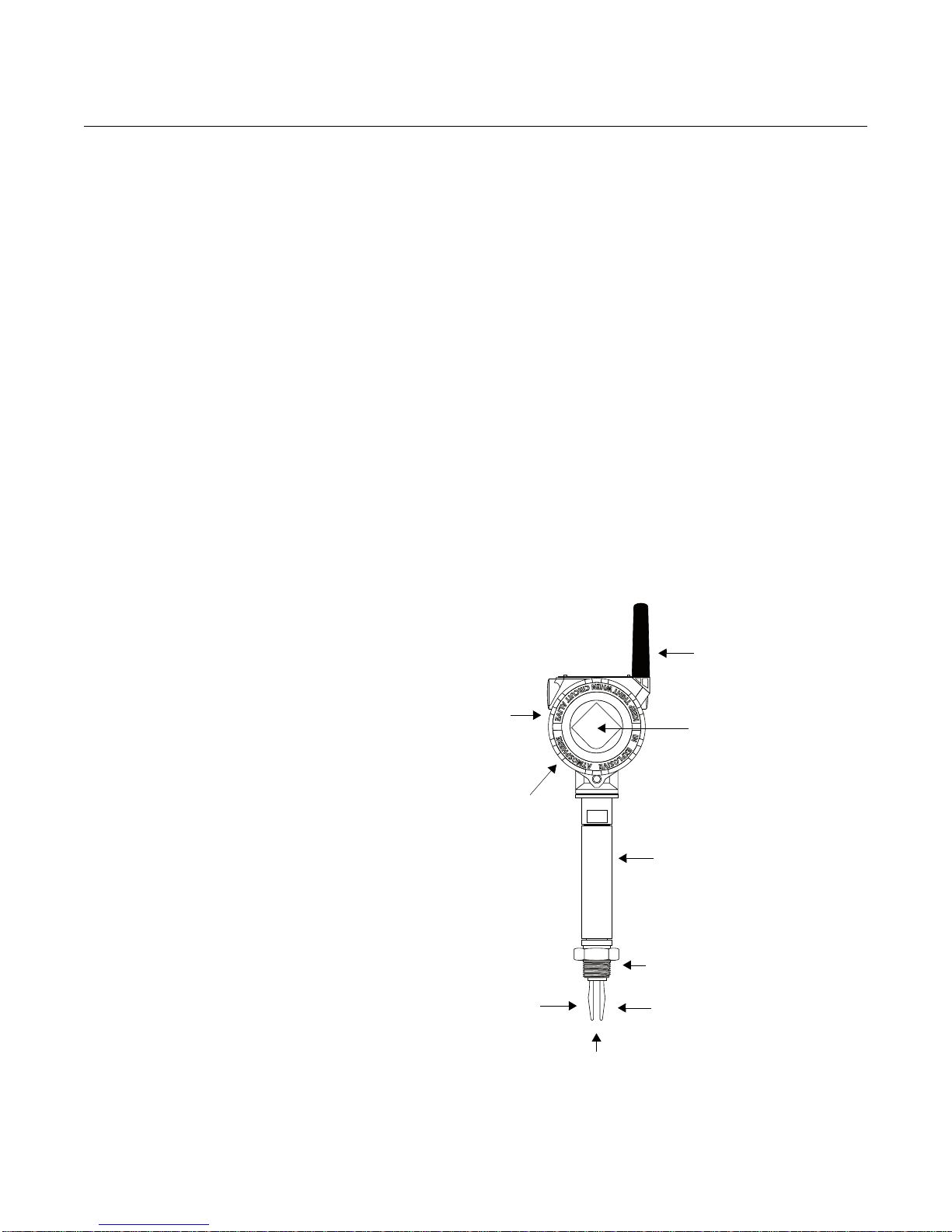
Reference Manual
Wetted Materials in 316/316L SST (1.4401/1.4404), or
Alloy C (UNS N10002) and Alloy C-276 (UNS N10276)
NEMA Type 4X (IP66)
Housing in Aluminum.
Removable Covers on
Both Sides
Short Fork Length
with Extensions
up to 118 in. (3 m)
Threaded,
Flanged, or
Hygienic
Connections
Thermal Tube
(2160***E Only)
Fast Drip Design
ATEX, FM, CSA, and
IECEx Intrinsically Safe
Antenna
Optional LCD
Display
00809-0100-4160, Rev AB
March 2010
Rosemount 2160
ABOUT THE 2160
Switch Overview The Rosemount 2160 WirelessHART is a wireless liquid point level switch.
Based on vibrating short fork technology, the 2160 is suitable for virtually all
liquid applications:
• Vir tually unaf fected by flow, bubbles, turbulence, foam, vibration, solids
content, coating, properties of the liquid, and product variations
• Operation in extreme temperatures of –94 to 500 °F (–70 to 260°C)
• No need for calibration and requires minimum installation procedures
• No moving parts or crevices means virtually no maintenance
• Electronic self-checking and condition monitoring
• Programmable switching delay for tur bulent or splashing applications
• Short fork length with extensions up to 118 in. (3 m)
• “Fast Drip” fork design give s quick response time
• General area and Intrinsically Safe options
This combination of features makes the 2160 an ideal choice for a wide
variety of challenging applications in the chemical, power generation, and oil
and gas industries.
Figure 1-1. Features of the 2160
1-3
Page 12

Reference Manual
00809-0100-4160, Rev AB
Rosemount 2160
March 2010
Measurement Principle The Rosemount 2160 is designed using the principle of a tuning fork.
A piezo-electric crystal oscillates the forks at their natural frequency . Changes
to this frequency are continuously monitored.
The frequency of the vibrating fork sensor changes depending on the medium
in which it is immersed. The denser the liquid, the lower the frequency.
When used as a low level alarm, the liquid in the tank or pipe drains down
past the fork, causing a change of natural frequency that is detected by the
electronics and switches the output state to a Dry condition.
When the 2160 switch is used as a high level alarm, the liquid rises in the
tank or pipe making contact with the fork, causing the output state to switch to
a Wet condition.
The output state, along with other parameters, are regularly transmitted over
a secure wireless connection to a Smart Wireless Gateway.
Short Fork Technology The natural frequency (~1300Hz) of the fork avoids interference from plant
vibration that may cause false switching. This allows for minimum intrusion
into the tank or pipe through the use of a short fork.
Using Short Fork Technology, the Rosemount 2160 can be used in almost all
liquid applications. Extensive research has maximized the operational
effectiveness of the fork design, making it suitable for most liquids including
coating liquids, aerated liquids, and slurries.
Special Features Instrument Health Monitor and Continuous Self-Check
The 2160 continuously performs instrument health diagnostics to self-check
the condition of the fork and sensor. These diagnostics can detect damage to
the forks including corrosion, internal or external damage to the forks, and
breakages to the internal wiring.
See “Operation Mode” on page 2-8 for further information.
Fork Design
The “fast drip” fork design draws liquid away from the fork tips, and together
with a short switching delay , allows the 2160 to react quickly and with greater
sensitivity to density variations.
Battery Powered
The 2160 is powered by an integral battery . The fork sensor requires very little
power and the battery life remains long even with fast update rates.
See “Battery Installation” on page 3-6 for further information.
Adjustable Time Delay
There is also a user-selectable time delay to virtually eliminate the risk of false
switching in turbulent or splashing applications.
See “Sensor Output Delay” on page 2-9 for further information.
1-4
Page 13
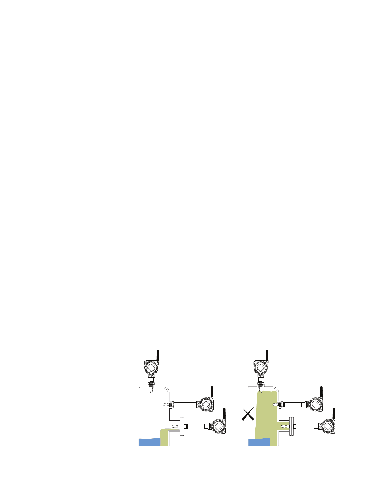
Reference Manual
00809-0100-4160, Rev AB
March 2010
Rosemount 2160
Rosemount 2160
Application Examples
For most liquids, including coating, aerated liquids and slurries, the fun ction is
virtually unaffected by flow, turbulence, bubbles, foam, vibration, solid
particles, build-up, or properties of the liquid.
See Figure 1-5 on page 1-8 for application examples.
The 2160 switch can be used in hazardous (IS) or non-hazardous (safe)
areas but supports higher process temperatures up to 500 °F (260 °C).
The switch can be mounted in almost any position in an open or closed tank
or pipe. There is a wide range of threaded, flanged, or hygienic connections.
Application Considerations:
• Ensure the process is operating within the instrument op er a ting
temperature and pressure ranges (see “Specifications” on page A-1)
• Ensure the liquid viscosity is within the recommended viscosity range
(see “Specifications” on page A-1)
3
• Check that the liquid density is higher than 31.2 lb/ft
(see “Specifications” on page A-1)
• Check for risk of build -up on the forks
Avoid situations where drying and coating products may create
excessive build-up (see Figure 1-2)
• Ensure there is no risk of ‘brid ging’ the forks
Examples of products that can create bridgin g of forks are dense p aper
slurries and bitumen
• Check the solids content in the liquid
(500 kg/m3)
Figure 1-2.
Avoid Product Build-up
As a guideline, the maximum solid particle diameter in the liquid is
0.2 in. (5 mm). Extra consideration is needed when dealing with
particles bigger than 0.2 in. (5 mm). Consult the factory for advice.
• Problems may occur if product coats and dries causing caking.
• In almost all cases, the 2160 is insensitive to foams (i.e. does not see
the foam).
However in rare occasions, some very dense foams may be seen as
liquid; a known example of this is found in ice-cream and orange juice
manufacturing.
OK
1-5
Page 14
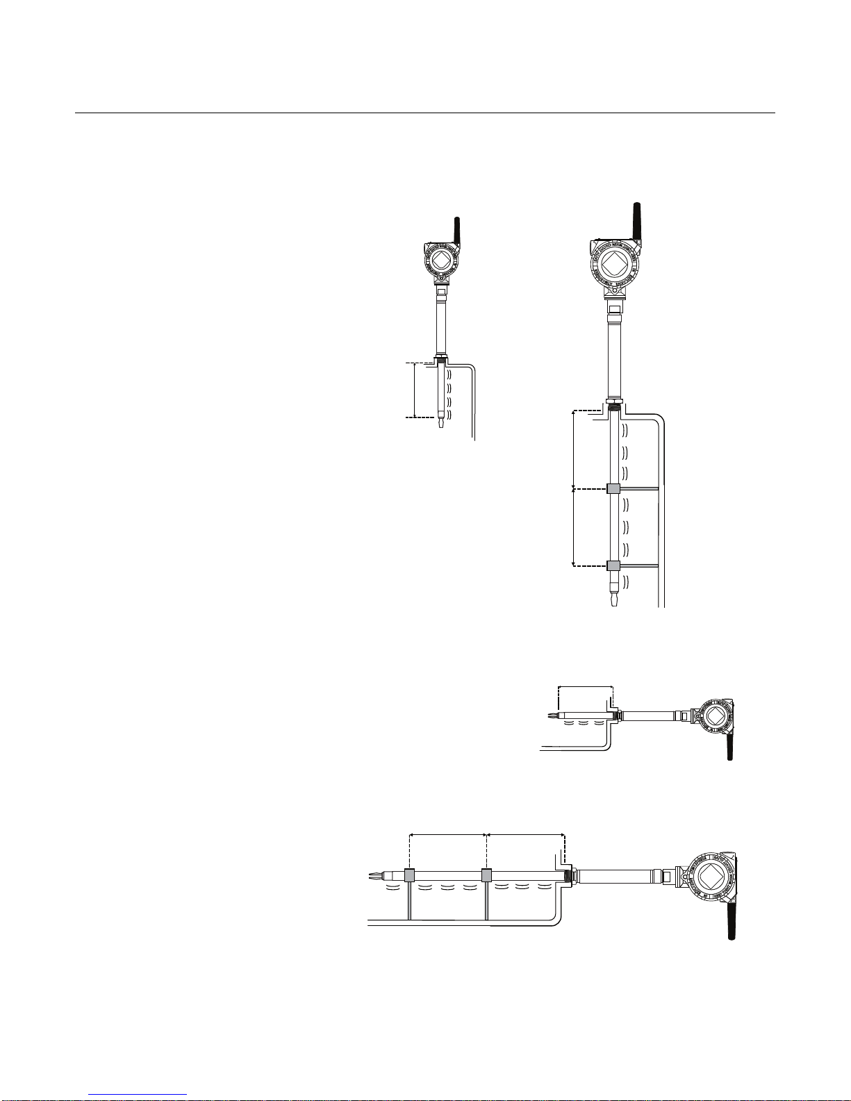
Rosemount 2160
3.28 ft.
(1.0 m)
3.28 ft.
(1.0 m)
3.28 ft.
(1.0 m)
3.28 ft.
(1.0 m)
Maximum
3.28 ft.
(1.0 m)
Maximum
3.28 ft.
(1.0 m)
Extended Fork Supports
Figure 1-3. Supports Neede d for
Extended Forks
OK
Reference Manual
00809-0100-4160, Rev AB
March 2010
OK
OK
OK
1-6
Page 15
Reference Manual
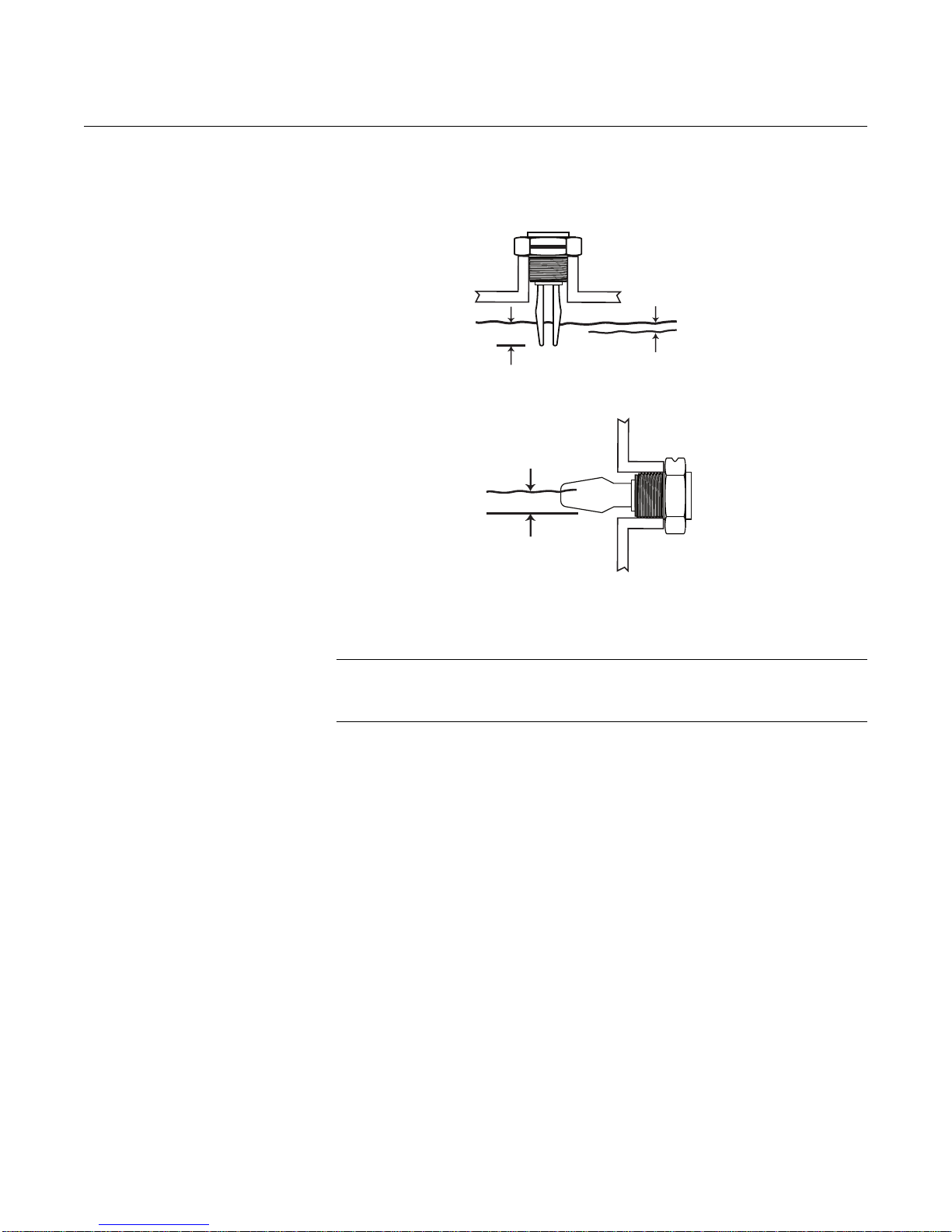
SP = Switchpoint (H20)
HY = Switching Hysteresis
±0.039 in.
(1 mm)
±0.5 in.
(13 mm)
±0.5 in.
(13 mm)
00809-0100-4160, Rev AB
March 2010
Switchpoint
Figure 1-4. Switchpoint
Rosemount 2160
SP
HY
SP
NOTE:
A lower density media will give a switchpoint closer to the connection.
A higher density media will give a switchpoint closer to the fork tip.
1-7
Page 16
Rosemount 2160
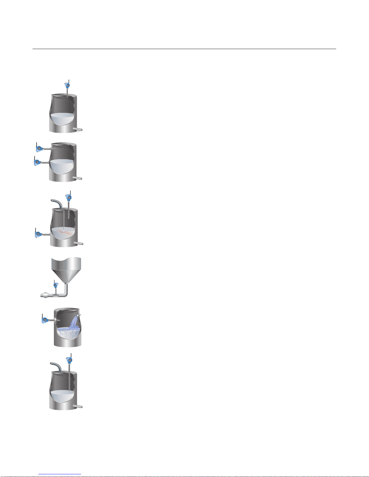
Figure 1-5. Rosemount 2160
Application Examples
Overfill Protection
Spillage caused by overfilling can be hazardous to people and the environment, resulting in
lost product and potentially high clean up costs.
High and Low Level Alarm
Maximum and minimum level detection in tanks containing different types of liquids are ideal
applications. The Rosemount 2160 is robust and operates continuously across the
temperature range of –94 to 500 °F (–70 to 260 °C) and operating p ressures of up to 1450 psig
(100 barg), making it perfect for use as a high or low level alarm. It is common practice to have
an independent high level alarm switch as a backup to an installed level device in case of
primary failure.
Reference Manual
00809-0100-4160, Rev AB
March 2010
Pump Control (Limit Detection)
Batch processing tanks often contain stirrers and agitators to ensure mixing and product
‘fluidity’. The standard user-selectable time delay, from 0 to 3600 seconds, virtually eliminates
the risk of false switching from splashing.
Pump Protection or Empty Pipe Detection
With the fork projecting only 2 in. (50 mm) (dependant on connection type), the 2160 can be
installed in small diameter pipes. Short forks mean minimum intrusion on the wetside and
allow for simple, low cost installation at any angle into pipes or tanks. The 2160 is ideal for
reliable pump control and can be used to protect against pumps running dry.
Extreme Temperature Applications
The 2160***E is designed for extreme temperatures and is suitable for continuous operation
within the temperature range of –94 to 500 °F (–70 to 260 °C).
Hygienic Applications
With the highly polished forks option providing a surface finish (Ra) better than 0.4 µm, the
2160 meets the most stringent hygienic requirements used in food and beverage, and
pharmaceutical applications.
1-8
Page 17
Reference Manual
NOTICE
00809-0100-4160, Rev AB
March 2010
Rosemount 2160
SERVICE SUPPORT To expedite the return process outside of the United States, contact the
nearest Emerson Process Management representative.
Within the United States, call the Emerson Process Management Instrument
and V alves Response Center using the 1 800 654 77 68 toll-free numb er. This
center, available 24 hours a day, will assist you with any needed information
or materials.
The center will ask for product model and serial numbers, and will provide a
Return Material Authorization (RMA) number. The center will also ask for the
process material to which the product was last exposed.
Individuals who handle products exposed to a hazardous substance can avoid injury if they
are informed of, and understand, the hazard. If the product being returned was exposed to a
hazardous substance as defined by OSHA, a copy of the required Material Safety Data
Sheet (MSDS) for each hazardous substance identified must be included with the returned
goods.
PRODUCT
RECYCLING/DISPOSAL
Shipping considerations for wireless products:
The unit was shipped to you without the power module installed. Please remove the power
module prior to shipping.
Each power module contains two “C” size primary lithium batteries. These batteries are
regulated in transportation by the U. S. Department of Transportation, and are also covered
by IATA (Inter national Air Transport Association), ICAO (International Civil Aviation
Organization), and ARD (European Ground Transportation of Dangerous Goods). It is the
responsibility of the shipper to ensure compliance with these or any other local requirements.
Please consult current regulations and requirements before shipping.
The battery pack with the wireless unit contains two “C” size primary lithium/thionyl chloride
batteries. Each battery contains approximately 2.5 grams of lithium, for a total of 5 grams in each
pack. Under normal conditions, the battery materials are self-contained and are not reactive as
long as the batteries and the pack integrity are maintained. Care should be taken to prevent
thermal, electrical or mechanical damage. Contacts should be protected to prevent premature
discharge.
Recycling of equipment and packaging should be taken into consideration.
The product and packaging should be disposed of in accordance with local
and national legislation.
1-9
Page 18

Rosemount 2160
Reference Manual
00809-0100-4160, Rev AB
March 2010
1-10
Page 19
Reference Manual
00809-0100-4160, Rev AB
March 2010
Section 2 Configuration
Safety Messages . . . . . . . . . . . . . . . . . . . . . . . . . . . . . . . . . page 2-1
Overview . . . . . . . . . . . . . . . . . . . . . . . . . . . . . . . . . . . . . . . page 2-3
Required Bench Top Configuration . . . . . . . . . . . . . . . . .page 2-3
Device Network Configuration . . . . . . . . . . . . . . . . . . . . . page 2-4
Review Configuration Data . . . . . . . . . . . . . . . . . . . . . . . . page 2-5
Field Communicator . . . . . . . . . . . . . . . . . . . . . . . . . . . . . .page 2-7
Check Output . . . . . . . . . . . . . . . . . . . . . . . . . . . . . . . . . . . page 2-8
Basic Setup . . . . . . . . . . . . . . . . . . . . . . . . . . . . . . . . . . . . .page 2-8
LCD Display . . . . . . . . . . . . . . . . . . . . . . . . . . . . . . . . . . . . .page 2-10
Detailed Setup . . . . . . . . . . . . . . . . . . . . . . . . . . . . . . . . . . .page 2-11
Diagnostics and Service . . . . . . . . . . . . . . . . . . . . . . . . . .page 2-15
Calibration . . . . . . . . . . . . . . . . . . . . . . . . . . . . . . . . . . . . . . page 2-21
Simulation . . . . . . . . . . . . . . . . . . . . . . . . . . . . . . . . . . . . . . page 2-22
Advanced Functions for HART Protocol . . . . . . . . . . . . .page 2-23
Rosemount 2160
SAFETY MESSAGES Procedures and instructions in this section may require special precautions to
ensure the safety of the personnel performing the operations. Information that
raises potential safety issues is indicated by a warning symbol ( ). Refer to
the following safety messages before performing an operation preceded by
this symbol.
Warnings
Failure to follow these installation guidelines could result in death or serious injury
• The Rosemount 2160 is a wireless liquid level switch. It must be installed, connected,
commissioned, operated, and maintained by suitably qualified personnel only,
observing any national and local requirements that may apply
• Use the equipment only as specified in this manual. Failure to do so may impair the
protection provided by the equipment
Explosions could result in death or serious injury
• Installation of the 2160 in a hazardous environment must be in accordance with the
appropriate local, national, and international standards, codes, and practices.
Please review the approvals section of the 2160 Reference Manual for any restrictions
associated with an installation
• Before connecting a Field Communicator in an explosive atmosphere, ensure the
installation is in accordance with intrinsically safe or non-incendive field wiring
practices
• Verify that the operating atmosphere of the level switch is consistent with the
appropriate hazardous locations certifications
External Surface may be hot
• Care must be taken to avoid possible burns
Process leaks could result in death or serious injury
• Install and tighten process connectors before applying pressure
• Do not attempt to loosen or remove process connectors while the 2160 is in service
www.rosemount.com
Page 20

Rosemount 2160
Reference Manual
00809-0100-4160, Rev AB
March 2010
Electrical shock could cause death or serious injury
• If the liquid level switch is installed in a high voltage environment and a fault condition
or installation error occurs, high voltage may be present on leads and terminals
• Use extreme caution when making contact with the leads and terminals
• Make sure that power to the 2160 is off while making connections
2-2
Page 21

Reference Manual
00809-0100-4160, Rev AB
March 2010
Rosemount 2160
OVERVIEW This section contains information on commissioning and verification that
should be performed prior to installation.
®
Field Communicator and AMS
functions. For convenience, Field Communicator fast key sequences are
labeled “Fast Keys” for each software function below the appropriate
headings.
Example Software Function
Fast Keys
1, 2, 3, etc.
instructions are given to perform configuration
REQUIRED BENCH TOP
CONFIGURATION
Bench top configuration requires a Field Communicator, AMS, or any
WirelessHART Communicator.
Remove the power module-side housing cover to expose the termin al block
and HART communication terminals, then connect the power module to
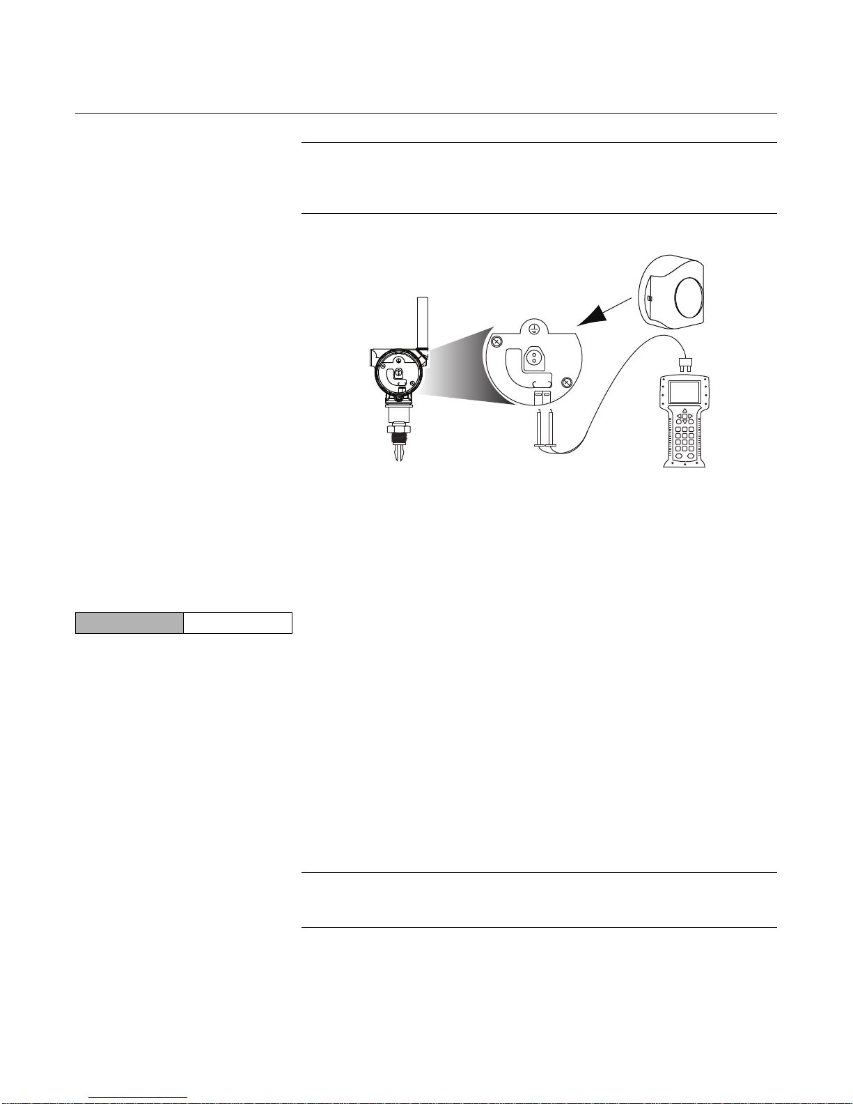
power the unit for configuration. Connect the Field Communicator leads to the
terminals labeled “COMM” on the terminal block. See Figure 2-1 on page 2-4.
Bench top configuration consists of testing the transmitter and verifying
transmitter configuration data. The 2160 can be configured before or after
installation (field hook-up). However, configuring the 2160 on the bench
before installation using a Field Communicator ensures that all network
settings are working correctly.
When using a Field Communicator , any configuration ch anges made must be
sent to the 2160 by using the “Send” key (F2). AMS configuration changes are
implemented when the “Apply” button is clicked.
AMS Wireless Configurator
®
AMS is capable of connecting to devices either directly, using a HART
modem, or wirelessly via the Smart Wireless Gateway.
When configuring on the bench with a HART modem, double click the device
icon, then choose the Configure/Setup tab (or right click and select
Configure/Setup).
When configuring with the Gateway , double click the device icon, then choose
the Configure/Setup tab (or right click and select Configure/Setup).
Connection Diagrams Bench Hook-up
To check or change the configuration using a Field Communicator, enter the
following Fast Key sequence: 2, 1, 3.
Connect the bench equipment as shown in Figure 2-1, and turn on the Field
Communicator by pressing the ON/OFF key or log into AMS. The Field
Communicator or AMS will search for a HART -compatible device and indicate
when the connection is made. If the Field Communicator or AMS fail to
connect, it indicates that no device was found. If this occurs, refer to
Section 6: Troubleshooting.
Field Hook-up
Figures 2-1 illustrates the wiring for a field hook-up with a Field Communicator
or AMS. The Field Communicator or AMS may be connected to “COMM” on
the terminal block of the 2160.
2-3
Page 22
Rosemount 2160
COMM
P/N 00753-9200-0010
Figure 2-1.
Field Communicator Connection
Reference Manual
00809-0100-4160, Rev AB
March 2010
NOTE
Before connecting a Field Communicator in an explosive atmosphere, make
sure the instruments are installed in acco rdance with intrinsically safe or
non-incendive field wiring practices.
P/N 00753-9200-0010
COMM
P/N 00753-9200-0010
COMM
For HART communication, a Device Description (DD) file for the Rosemount
2160 is required.
DEVICE NETWORK
CONFIGURATION
Join Device to Network To communicate with the Smart Wireless Gateway, and ultimately the
Fast Keys
2, 1, 1
Information System, the 2160 must be configured to communicate with the
wireless network. This step is the wireless equivalent of connecting wires from
a transmitter to the host system.
1. From the Home screen, select 2: Configure.
2. Select 1: Guided Setup.
3. Select 1: Join Device to Network.
Using AMS or a Field Communicator, enter the Network ID and Join Key so
they match the Network ID and Join Key of the Gateway and the other
devices in the network. If the Network ID and Join Key are not identical, the
2160 will not communicate with the network.
2-4
When using a Field Communicator, the Network ID can be configured by
entering Fast Key sequence: 2, 2, 1, 1. The Join Key can also be configured
using a Field Communicator with the Fast Key sequence: 2, 2, 1, 2.
NOTE
The Network ID and Join Key may be obtained from the
Setup>Network>Settings page on the Gateway’s web server.
Page 23

Reference Manual
00809-0100-4160, Rev AB
March 2010
Rosemount 2160
Configure Update Rate The final device network configuration piece is the Update Rate which, by
Fast Keys
2, 2, 2
default, is 1 minute. It can be changed at commissioning, or at any time, by
using AMS or the Gateway’s web server. The Update Rate should be
between 4 seconds and 60 minutes.
1. From the Home screen, select 2: Configure.
2. Select 1: Guided Setup.
3. Select 2: Configure Update Rate.
Remove Power Module After the bench top and network device configuration is completed, remove
the Power Module and replace the housing cover. The Power Module should
be inserted only when the device is ready to be installed.
When the device is installed, insert the Power Module and clo se the housing
cover securely. Always ensure a proper seal so that metal touches metal, but
do not over tighten.
Use caution when handling the Power Module. The Power Module may be
damaged if dropped from heights in excess of 20 ft. (6,1 m).
REVIEW
CONFIGURATION DATA
The following is a list of factory default configurations that can be viewed by
using the Field Communicator or AMS. Follow the steps below to review the
level switch configuration information.
NOTE
Information and procedures in this section that make use of Field
Communicator fast key sequences and AMS assume that the 2160 and
communication equipment are connected, powered, and operating correctly.
Review Operation Mode To view the operation mode:
Fast Keys
2, 2, 2, 1, 1
1. From the Home screen, select 2: Configure.
2. Select 2: Manual Setup.
3. Select 2: Operation.
4. Select 1: Application.
5. Select 1: Operation Mode.
The default operating mode is Normal Mode. Other options are Enhanced
Operation Mode (Fault=Wet) or Enhanced Operation Mode (Fault=Dry).
2-5
Page 24
Rosemount 2160
Reference Manual
00809-0100-4160, Rev AB
March 2010
Review Device
Information
Fast Keys
Review Radio
Information
Fast Keys
2, 2, 4, 3
2, 2, 4, 4
To view device information:
1. From the Home screen, select 2: Configure.
2. Select 2: Manual Setup.
3. Select 4: Device Information.
4. Select 3: Device.
5. Select from the corresponding number to view each field:
1 Manufacturer
2 Device Type
3 Final Assembly Number
4 Universal
5 Field Device
6 Software
7 Hardware
8 Descriptor
9 Message
10 Date
11 Model Number
12 SI Unit Restriction
13 Country
14 Device ID
To view radio information:
1. From the Home screen, select 2: Configure.
2. Select 2: Manual Setup.
3. Select 4: Device Information.
4. Select 4: Radio.
5. Select from the corresponding number to view each field:
Review Device
Temperature Information
Fast Keys
2-6
2, 2, 3, 1
1 Manufacturer
2 Device Type
3 Device Revision
4 Software Revision
5 Hardware Revision
To view the device temperature information:
1. From the Home screen, select 2: Configure.
2. Select 2: Manual Setup.
3. Select 3: Device Temperature.
4. Select 1: Electronics Temperature.
5. Select from the corresponding number to view each field:
1Unit
2 Maximum
3 Minimum
Page 25
Reference Manual
00809-0100-4160, Rev AB
March 2010
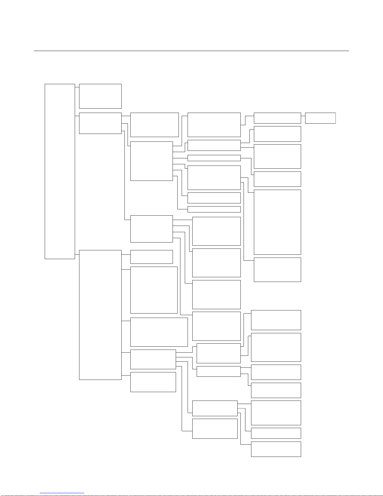
FIELD COMMUNICATOR
Menu Tree
1. Overview
2. Configure
3. Service Tools
(*1) This Option Appears When There Are Previous Alerts.
(*2) Only One Option Appears Depending On Which Has Been Selected.
1. Active Alerts
2. Communication Status
3. PV – 1.0=Wet /0.0=Dry
4. PV Status
5. Last Update Time
1. Guided Setup
2. Manual Setup
3. Alert Setup
1. Alerts
2. Variables
3. Communications
4. Maintenance
5. Simulate
1. Join Device To Network
2. Configure Update Rate
3. Configure Device Display
4. Configure Alerts
5. Basic Setup
1. Wireless
2. Operation
3. Device Temperature
4. Device Information
5. Device Display
6. Other
1. Alert 1
2. Alert 2
3. Alert 3
4. Alert 4
1. Active Alerts
2. History (*1)
1. PV – 1.0=Wet /0.0=Dry
2. PV Status
3. Sensor Frequency
4. Sensor Frequency Status
5. Electronics Temperature
6. Electronics Temperature
Status
7. Supply Voltage
8. Supply Voltage Status
9. Last Update Time
1. Join Status
2. Communication Status
3. Join Mode
4. Number of Available Neighbors
5. Number of Advertisements Heard
6. Number of Join Attempts
1. Diagnostics
2. Counters / Timers
3. Calibrate
4. Others
1. Sensor Output Mode
2. Fork Frequency
3. Electronics Temperature
4. Supply Voltage
1. Network ID
2. Join Device To Network
3. Broadcast Rates
4. Power Mode
5. Power Source
1. Application
2. Sensor
1. Electronics Temperature
1. Tag
2. Long Tag
3. Device
4. Radio
5. Write Protect
1. Mode
2. Display Options
1. Measurement and Status Log
1. Configure Alert 1
2. Mode
3. Variable
4. Direction
5. Limit
6. Band
1. Configure Alert 2
2. Mode
3. Variable
4. Direction
5. Limit
6. Band
1. Configure Alert 3
2. Mode
3. Variable
4. Direction
5. Limit
6. Band
1. Configure Alert 4
2. Mode
3. Variable
4. Direction
5. Limit
6. Band
1. Sensor
2. Sensor Status
3. Dry Fork Frequency /
Switch Points
1. Counters
2. Timers
1. Sensor Calibration
2. Reset Calibration
3. Sensor Compensation
1. Perform Master Reset
2. Measurement History
3. Advertise to New Devices
4. Load User Defaults
Rosemount 2160
1. Configure Update Rate
2. Message 1
1. Operation Mode
2. Sensor Output Delay
3. Media Density
1. Sensor Stabilization Time
2. Measurement Time
3. Allowable Change In
Dry Fork Frequency
4. Sensor Fault Delay
1. Unit
2. Maximum
3. Minimum
1. Manufacturer
2. Device Type
3. Final Assembly Number
4. Universal
5. Field Device
6. Software
7. Hardware
8. Descriptor
9. Message
10.Date
11.Model Number
12.SI Unit Restriction
13.Country
14.Device ID
1. Manufacturer
2. Device Type
3. Device Revision
4. Software Revision
5. Hardware Revision
1. Sensor Frequency
2. Temperature Compensation
3. Uncompensated Frequency
4. Sensor State
1. Dry Fork Frequency
2. Dry to Too Dry
3. Dry to Indeterminate
4. Wet to Indeterminate
5. Wet to Too Wet
6. Zero
1. Sensor Wet Count
2. Calibration Count
3. Fault Control
1. Time Since Output Change
2. Total Time Dry
3. Total Time Wet
1. Dry Fork Frequency
2. Sensor Frequency
3. Calibrate Dry Fork
4. Sensor Calibration Status
5. Calibration Count
1. Restore Factory Calibration
2. Restore Site Calibration
1. Calibration Temperature
2. Temperature Compensation
3. Process Temperature
1. Burst Option 1
2. Update Rate 1
(*2)
2-7
Page 26

Reference Manual
00809-0100-4160, Rev AB
Rosemount 2160
March 2010
CHECK OUTPUT Before performing other level switch operations, ensure the 2160 is oper ating
properly by checking the process variables.
Variables To view the Variables menu:
Fast Keys
3, 2
1. From the Home screen, select 3: Service Tools.
2. Select 2: Variables.
The variable menu displays the following proces s var iab le s:
• PV – level switch output state of 0.0 (Dry) or 1.0 (Wet)
• PV Status – valid or fault status (see “Troubleshooting” on page 6-2)
• Sensor Frequency – the frequency of the vibrating fork
• Sensor Frequency State – valid or fault status
• Electronics Temperature – the temperature inside the 2160 housing
• Electronics Temperature Status – valid or fault status
• Supply Voltage – the input voltage to the level switch
• Supply Voltage Status – valid or fault status
• Last Update Time – elapsed time since the last data update
BASIC SETUP
Temperature Units The Unit setting allows the Electronics Temperature process variable to be
Fast Keys
2, 2, 3, 1
displayed in Farenheit (°F) or Celsius (°C).
To view the electronics temperature menu:
1. From the Home screen, select 2: Configure.
2. Select 2: Manual Setup.
3. Select 3: Device Temperature.
4. Select 1: Electronics Temperature.
The electronics temperature menu displays the following:
• Unit – Change/View measurement units for Electronics Temperature
• Maximum – View the highest measured electronics temperature
• Minimum – View the lowest measured electronics temperature
Operation Mode The 2160 has three operation modes:
Fast Keys
2, 2, 2, 1, 1
• Standard – Default operation mode for no sensor fault detection
• Enhanced (Fault=WET) – Output is forced to Wet when fault detected
(see Figure A-2 on page A-3)
• Enhanced (Fault=DRY) – Output is forced to Dry when fault detected
(see Figure A-2 on page A-3)
2-8
To change or view the operation mode:
1. From the Home screen, select 2: Configure.
2. Select 2: Manual Setup.
3. Select 2: Operation.
4. Select 1: Application.
5. Select 1: Operation Mode.
Page 27

Reference Manual
00809-0100-4160, Rev AB
March 2010
Rosemount 2160
Sensor Output Delay When the 2160 detects a change in process conditions from wet-to-dry or
Fast Keys
2, 2, 2, 1, 2
dry-to-wet, the Sensor Output Delay parameter causes a de lay of up to 3600
seconds before a new process condition is indicated in the process variables.
If, for example, there are waves in a tank, then the 2160 may intermittently
detect a change in process conditions. The sensor output delay ensures that
the 2160 fork is dry or wet for a period before switching.
Depending on the application, a suitable delay can prevent const ant switching
of the output state.
NOTE
The delay re-starts each time a change in process conditions is detected.
To change or view the sensor output delay:
1. From the Home screen, select 2: Configure.
2. Select 2: Manual Setup.
3. Select 2: Operation.
4. Select 1: Application.
5. Select 2: Sensor Output Delay.
Media Density The frequency of the vibrating fork sensor can be affected by the process
Fast Keys
2, 2, 2, 1, 3
liquid density. Use Media Density to select one of the following options:
• Normal – Select when the liquid specific gravity is between 0.7 and 2.0
• Low – Select when the liquid specific gravity is less than 0.7
• High – Select when the liquid specific gravity is greater than 2.0
NOTE
If the liquid specific gravity is unknown, keep the default setting of Normal.
Write Protect The 2160 has a software write protect security feature.
Fast Keys
Measurement and
Status Log
Fast Keys
2, 2, 4, 5
2, 2, 6, 1
The change or view write protect security settings:
1. From the Home screen, select 2: Configure.
2. Select 2: Manual Setup.
3. Select 4: Device Information.
4. Select 5: Write Protect.
Measurement and Status Log records previous PV measurement values.
To enable or disable the logging:
1. From the Home screen, select 2: Configure.
2. Select 2: Manual Setup.
3. Select 6: Other.
4. Select 1: Measurement and Status Log.
Follow on-screen instructions to enable or disable the logging.
2-9
Page 28

Rosemount 2160
LCD DISPLAY
Reference Manual
00809-0100-4160, Rev AB
March 2010
LCD Display
Configuration
Fast Keys
2, 1, 3
The LCD display indicates output and abbreviated diagnostic messages.
NOTE
Use Rosemount Wireless LCD Part Number: 00753-9004-0002.
The LCD display features a four-line display and a bar graph. The first line of
five characters displays the output description, the second line of seven digits
displays the actual value, the third line of six characters displays engineering
units, and the fourth line displays “Error” when there is an alarm condition.
The LCD display can also display diagnostic messages. The bar graph
represents the network connectivity status.
See “LCD Screen Messages” on page 5-3 for more information on LCD
messages.
To change or view LCD display options:
1. From the Home screen, select 2: Configure.
2. Select 1: Guided Setup.
3. Select 3: Configure Device Display.
Alternatively, to manually change or view LCD display options:
1. From the Home screen, select 2: Configure.
2. Select 2: Manual Setup.
3. Select 5: Device Display.
4. Follow the on-screen instructions to configure Mode and Display
Options parameters.
2-10
Page 29
Reference Manual
Deadband
Assigned Value
Alert Set Point
Alert “OFF” Alert “ON” Alert “OFF”
Units of Measurement
Time
Deadband
Assigned Value
Alert Set Point
Alert “OFF” Alert “ON” Alert “OFF”
Units of Measurement
Time
00809-0100-4160, Rev AB
March 2010
Rosemount 2160
DETAILED SETUP
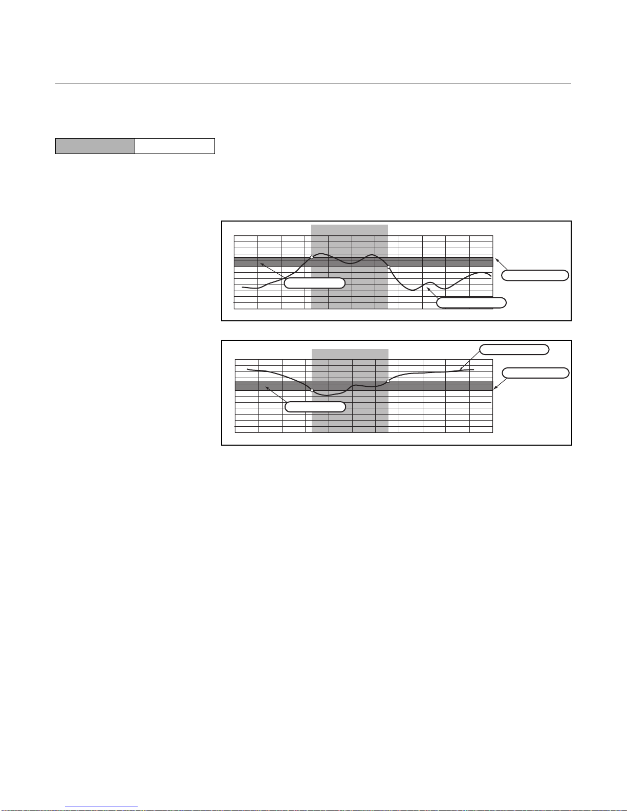
Process Alerts Alerts can be configured to output a HART message when a configured da ta
Fast Keys
2, 1, 4
point is exceeded. A process alert is transmitted continuously if a set point for
a process variable is exceeded and the alert mode is enabled.
An alert is displayed on a Field Communicator, AMS status screen, or in the
error section of the optional LCD display. The alert is reset when the assigned
value (process variable) returns within it s normal range.
Example 1: Rising Alert
Example 2: Falling Alert
To change or view the process alerts:
1. From the Home screen, select 2: Configure.
2. Select 1: Guided Setup.
3. Select 4: Configure Alerts.
4. Follow the on-screen instructions to configure up to four alerts (Alert 1,
Each alert requires the following information:
To view active or previous process alerts:
1. From the Home screen, select 3: Service Tools.
2. Select 1: Alerts.
3. Select Active Alerts to view active alerts, or select History to view
Alert 2, Alert 3, and Alert 4).
•Mode – Disabled (default) or enabled alert
• Variable – Select Output State, Sensor Frequency,
Electronics Temperature, or Supply Voltage
• Direction – Rising or falling alert
• Limit – Alert set point (in same units as the variable)
•Band – Hysteresis data point (in same units as the variable)
for transition from deadband zone to new alert state
previous alerts.
2-11
Page 30
Rosemount 2160
Reference Manual
00809-0100-4160, Rev AB
March 2010
Sensor Stabilization
Time
Fast Keys
2, 2, 2, 2, 1
The time needed for the fork sensor to reach a stable vibration may vary
depending on the process conditions. Sensor Stabilization Time sets a
delay before taking a frequency measurement.
The default setting is 60 ms. It can be set to a time in the rang e 20 to 1000 ms
and is adjustable in 20 ms steps. Alternatively, the setting AUTO is for the
Rosemount 2160 to automatically calculate a delay.
To change or view the sensor stabilization time:
1. From the Home screen, select 2: Configure.
2. Select 2: Manual Setup.
3. Select 2: Operation.
4. Select 2: Sensor.
5. Select 1: Sensor Stabilization Time.
6. Follow the on-screen instructions to configure a delay.
Measurement Time The time needed for the fork sensor to take an accurate measurement after
Fast Keys
2, 2, 2, 2, 2
reaching a stable vibration may vary depending on the process conditions.
Measurement Time sets a delay before taking a frequency measurement.
The default setting is 60 ms. It can be set to a time in the rang e 20 to 1000 ms
and is adjustable in 20 ms steps. Alternatively, the setting AUTO is for the
Rosemount 2160 to automatically calculate a delay.
To change or view the measurement time:
Allowable Change In
Dry Fork Frequency
Fast Keys
2, 2, 2, 2, 3
1. From the Home screen, select 2: Configure.
2. Select 2: Manual Setup.
3. Select 2: Operation.
4. Select 2: Sensor.
5. Select 2: Measurement Time.
6. Follow the on-screen instructions to configure a delay.
When the 2160 is re-calibrated in the field, a co mparison is made between the
new dry fork frequency and original factory-set Dry Fork Frequency value.
If the difference is greater than the allowabl e change value, the re-calibration
is rejected. Check the fork for damage, corrosion, or coating, and clean the
fork if necessary before re-trying.
The default setting is 100 Hz. It can be set to a value in the ra nge 1 to 2 55 Hz.
NOTE
Fast Key sequence is 3, 4, 3, 1 for the original factory-set Dry Fork Frequency.
To change or view the allowable change:
1. From the Home screen, select 2: Configure.
2. Select 2: Manual Setup.
3. Select 2: Operation.
4. Select 2: Sensor.
5. Select 3: Allowable Change In Dry Fork Frequency.
6. Follow the on-screen instructions to configure the allowable change.
2-12
Page 31

Reference Manual
00809-0100-4160, Rev AB
March 2010
Rosemount 2160
Sensor Fault Delay When the 2160 is operating in Enhanced Mode and detects a fork sensor
Fast Keys
2, 2, 2, 2, 4
fault, Sensor State (page 2-17) indicates a Fault state after a delay set by
Sensor Fault Delay.
The default setting is 600 seconds. It can be a maximum of 3600 seconds.
NOTE
When the 2160 is operating in Normal Mode, a fork sensor fault is not
detected and Sensor State (page 2-17) continues to indicate a Valid state.
To change or view the sensor fault delay:
1. From the Home screen, select 2: Configure.
2. Select 2: Manual Setup.
3. Select 2: Operation.
4. Select 2: Sensor.
5. Select 4: Sensor Fault Delay.
6. Follow the on-screen instructions to configure the sensor fault delay.
Update Rate 1 During normal operations, the sampling rate of the fork sensor is set by
Fast Keys
2, 2, 1, 3, 1, 2
Update Rate 1. This is the rate scheduled data is transmitted over the secure
wireless network and can be set to between 4 seconds and 60 minutes.
To change or view the update rate:
1. From the Home screen, select 2: Configure.
2. Select 2: Manual Setup.
3. Select 1: Wireless
4. Select 3: Broadcast Rates.
5. Select 1: Configure Update Rate.
6. Select 2: Update Rate 1.
7. Follow the on-screen instructions to configure the update rate.
2-13
Page 32

Reference Manual
00809-0100-4160, Rev AB
Rosemount 2160
March 2010
Power Mode For configuration and diagnostic purposes, the 2160 can be put into an
Fast Keys
2, 2, 1, 4
Always On power mode. The fork sensor is energized con tinuously and a new
measurement is completed, typically, every 500 ms.
The Always On power mode causes a much higher drain on the battery, and
so the 2160 reverts to the default Normal power mode after a settable period
of up to 10 minutes.
In Normal power mode, the fork sensor is energized for the period set by the
update rate (see “Update Rate 1” on page 2-13).
To view or change Power Mode:
1. From the Home screen, select 2: Configure.
2. Select 2: Manual Setup.
3. Select 1: Wireless.
4. Select 4: Power Mode.
5. Follow the on-screen instructions to configure the power mode.
Power Source A wireless device may be attached to a source of continuous power or to a
Fast Keys
2, 2, 1, 5
power source that drains over time (e.g. a battery). The 2160 is always
powered by Battery Power.
To view the Power Source:
1. From the Home screen, select 2: Configure.
2. Select 2: Manual Setup.
3. Select 1: Wireless.
4. Select 5: Power Source.
2-14
Page 33
Reference Manual
00809-0100-4160, Rev AB
March 2010
Rosemount 2160
DIAGNOSTICS AND
SERVICE
Diagnostics and service functions listed below are primarily for use after field
installation.
Master Reset The master reset function is used to reset the electronics and reset
Fast Keys
3, 4, 4, 1
parameters to their factory-set defaults.
To perform a master reset:
1. From the Home screen, select 3: Service Tools.
2. Select 4: Maintenance.
3. Select 4: Other.
4. Select 1: Master Reset.
5. Follow on-screen instructions to perform the reset.
Join Status Wireless devices join the secure network through a four step process:
Fast Keys
3, 3, 1
• Step 1. Network Found
• Step 2. Network Security Clearance Granted
• Step 3. Network Bandwidth Allocated
• Step 4. Network Join Complete
To view the join status of the Rosemount 2160:
1. From the Home screen, select 3: Service Tools.
2. Select 3: Communications.
3. Select 1: Join Status.
Communication Status This indicates whether or not the 2160 is connected to the secure network.
Fast Keys
3, 3, 2
To view the communication status of the 2160:
1. From the Home screen, select 3: Service Tools.
2. Select 3: Communications.
3. Select 2: Communication Status.
Join Mode This mode configures how the device attempts to join the secure network.
Fast Keys
3, 3, 3
Settable options are:
• Do Not Attempt to Join
•Join Now
• Attempt to Join immediately on Power Up or Reset
To change or view the join mode:
1. From the Home screen, select 3: Service Tools.
2. Select 3: Communications.
3. Select 3: Join Mode.
2-15
Page 34
Rosemount 2160
Reference Manual
00809-0100-4160, Rev AB
March 2010
Number Of Available
Neighbors
Fast Keys
3, 3, 4
Number of
Advertisements Heard
Fast Keys
3, 3, 5
In a self-organizing network, the more neighbors a device has, the more
robust the network will be.
To view the number of available neighbors:
1. From the Home screen, select 3: Service Tools.
2. Select 3: Communications.
3. Select 4: Number of Available Neighbors.
To view the number of advertising packets heard from other wireless devices:
1. From the Home screen, select 3: Service Tools.
2. Select 3: Communications.
3. Select 5: Number of Advertisements Heard.
Number of Join Attempts Too many join attempts result in the device considering the join attempt as
Fast Keys
3, 3, 6
failed. If this happens, re-check the Join Key and Network ID.
To view the number of attempts made to join a secure network:
1. From the Home screen, select 3: Service Tools.
2. Select 3: Communications.
3. Select 6: Number of Join Attempts
Sensor Frequency The vibrating fork frequency is indicated in Sensor Frequency after process
Fast Keys
3, 4, 1, 1, 1
condition adjustments.
NOTE
See “Sensor Stabilization Time” on page 2-12 and “Measurement Time” on
page 2-12 for process condition adjustments.
Sensor Frequency is the HART dynamic variable SV (Secondary Variable)
and can be indicated instead of the variable PV on the optional LCD display.
To view the vibrating fork frequency (sensor frequency):
1. From the Home screen, select 3: Service Tools.
2. Select 4: Maintenance.
3. Select 1: Diagnostics.
4. Select 1: Sensor.
5. Select 1: Sensor Frequency.
NOTE
The Fast Key sequence 3, 2, 3 also indicates Sensor Frequency.
2-16
Page 35
Reference Manual
00809-0100-4160, Rev AB
March 2010
Rosemount 2160
Temperature
Compensation
Fast Keys
Uncompensated
Frequency
Fast Keys
3, 4, 1, 1, 2
3, 4, 1, 1, 3
The frequency of the vibrating fork sensor may be affected by a varying
process temperature. If the 2160 knows the process temperature, it can
compensate accordingly and provide an improved frequency switching po int
(page 2-18) and trend calculation.
Use Temperature Compensation to set the temperature coefficient of the
vibrating fork sensor in units of Hz/°F (Hz/°C).
To change or view the temperature coefficient:
1. From the Home screen, select 3: Service Tools.
2. Select 4: Maintenance.
3. Select 1: Diagnostics.
4. Select 1: Sensor.
5. Select 2: Temperature Compensation.
Uncompensated Frequency indicates the vibrating fork frequency before
compensating for a varying process temperature.
To view the uncompensated frequency:
1. From the Home screen, select 3: Service Tools.
2. Select 4: Maintenance.
3. Select 1: Diagnostics.
4. Select 1: Sensor.
5. Select 2: Uncompensated Frequency.
Sensor State Sensor State indicates the present state of the vibrating fork.
Fast Keys
3, 4, 1, 1, 4
As the vibrating fork sensor becomes immersed in the process liquid, the
vibration frequency changes and the sensor state changes to Wet.
When the process liquid falls away from the fork, the vibration frequency
changes and the sensor state changes to Dry.
If the vibrating fork sensor is damaged, the frequency moves outside normal
operating limits and the sensor state changes to Too Dry, Too Wet, or Zero.
(See “Dry Fork Frequency / Switch Points” on page 2-18 for band limits.)
To view the sensor state:
1. From the Home screen, select 3: Service Tools.
2. Select 4: Maintenance.
3. Select 1: Diagnostics.
4. Select 1: Sensor.
5. Select 4: Sensor State.
2-17
Page 36

Rosemount 2160
Reference Manual
00809-0100-4160, Rev AB
March 2010
Dry Fork Frequency /
Switch Points
Fast Keys
3, 4, 3
The hysteresis for Sensor State transitions can be viewed in the dry fork
frequency and switch points menu:
• Dry Fork Frequency – The freque n cy re cord ed whe n ca lib r at ed in
dry conditions, and is typically 1.2 to 1.5 KHz
• Dry to Too Dry – The frequency above which th e sen so r
frequency is considered to be outside of the
normal Dry range. (Fault indicated when in
Enhanced Mode only).
• Dry to Indeterminate – The frequency below which the sensor
frequency is considered to be outside of the
normal Dry range. (Normal hysteresis –
see “Switchpoint” on page 1-7).
• Wet to Indeterminate – The frequency above which th e sen so r
frequency is considered to be outside of the
normal Wet range. (Normal hysteresis –
see “Switchpoint” on page 1-7).
• Wet to Too Wet – The frequency below which the sensor
frequency is considered to be outside of the
normal Wet range. (Fault indicated when in
Enhanced Mode only).
• Zero – The frequency below which the sensor
frequency is considered to be 0 Hz. (Fault
indicated when in Enhanced Mode only).
NOTE
When the 2160 is operating in Normal Mode, a 0 Hz sensor frequency
represents a Wet condition (and not a Fault). When operating in Enhanced
Mode, a 0 Hz sensor frequency represents a fault condition.
Sensor Status The 2160 indicates here if it is operating in a Valid or Fault state.
Fast Keys
Table 2-1.
Sensor Status Logic
(Normal Mode)
3, 4, 1, 2
Sensor Status is dep endent on the Sensor S t at e diagnostic (page 2-17) and
the Operation Mode configuration (page 2-8).
To view the sensor status:
1. From the Home screen, select 3: Service Tools.
2. Select 4: Maintenance.
3. Select 1: Diagnostics.
4. Select 2: Sensor Status.
Sensor Status Sensor State
Valid Dry 0.0 (Dry)
Valid Wet 1.0 (Wet)
(1) Sensor Fault Delay (page 2-13) does not delay the update of Sensor State when the operation mode
is Normal.
(1)
PV (Output Status)
NOTE:
If the operation mode is Normal, Sensor State cannot indicate Too Dry,
Too Wet, or Zero, and the Sensor Status always indicates a Valid state.
2-18
Page 37

Reference Manual
00809-0100-4160, Rev AB
March 2010
Table 2-2. Sensor Status Logic
(Enhanced Mode, Fault=Wet)
Table 2-3. Sensor Status Logic
(Enhanced Mode, Fault=Dry)
Rosemount 2160
Sensor Status Sensor State
Valid Dry 0.0 (Dry)
Fault Too Dry (Fault) 1.0 (Wet)
Valid Wet 1.0 (Wet)
Fault Too Wet (Fault) 1.0 (Wet)
Fault Zero 1.0 (Wet)
(1) Sensor Fault Delay (page 2-13) delays the update of Sensor State when the operation mode is
Enhanced.
(2) PV is not changed.
(3) PV is automatically changed to 1.0 (Wet process condition).
Sensor Status Sensor State
Valid Dry 0.0 (Dry)
Fault Too Dry (Fault) 0.0 (Dry)
Valid Wet 1.0 (Wet)
Fault Too Wet (Fault) 0.0 (Dry)
Fault Zero 0.0 (Dry)
(1) Sensor Fault Delay (page 2-13) delays the update of Sensor State when the operation mode is
Enhanced.
(2) PV is not changed.
(3) PV is automatically changed to 0.0 (Dry process condition).
(1)
(1)
PV (Output Status)
(2)
(3)
(2)
(3)
(3)
Output Status
(2)
(3)
(2)
(3)
(3)
Counters To view the Counters menu:
Fast Keys
3, 4, 2, 1
1. From the Home screen, select 3: Service Tools.
2. Select 4: Maintenance.
3. Select 2: Counters / Timers.
4. Select 1: Counters.
The Counters / Timers menu displays the following counters:
• Sensor Wet Count – This counter increments each time the PV
• Calibration Count – The 2160 is calibrated under reference
• Fault Count – This counter increments each time there is a
(Output State) changes from Dry to Wet. This
counter can be reset or preset by setting a new
value.
conditions at the factory. In special
circumstances, it may be re-calibrated in the
field and this increments the counter.
Fault condition (see “Sensor Status” on
page 2-18). This counter can be reset to zero.
2-19
Page 38

Rosemount 2160
Timers To view the Timers menu:
Fast Keys
3, 4, 2, 2
1. From the Home screen, select 3: Service Tools.
2. Select 4: Maintenance.
3. Select 2: Counters / Timers.
4. Select 2: Timers.
The Timers menu displays the following timers:
• Time Since
Output Change – The time elapsed since the PV (Output State)
• Total Time Dry – The total time that the PV (Output State) has
• Total Time Wet – The total time that the PV (Output State) has
NOTE
Units for the timers are days, hours, minutes, and seconds. Seconds are not
shown for long times.
Reference Manual
00809-0100-4160, Rev AB
March 2010
last changed from Wet to Dry or Dry to Wet.
This timer can be reset to zero.
been Dry. This timer can be reset to zero.
been Wet. This timer can be reset to zero.
2-20
Page 39
Reference Manual
00809-0100-4160, Rev AB
March 2010
Rosemount 2160
CALIBRATION
Dry Fork Frequency The 2160 detects the process is Wet or Dry by monitoring the vibrating fork
Fast Keys
3, 4, 3, 1, 1
sensor frequency. Dry Fork Frequency is set when calibrated under Dry
process conditions at the factory.
See also “Dry Fork Frequency / Switch Points” on page 2-18 for associated
parameters.
To view the dry fork frequency:
1. From the Home screen, select 3: Service Tools.
2. Select 4: Maintenance.
3. Select 3: Calibrate.
4. Select 1: Sensor Calibration.
5. Select 1: Dry Fork Frequency.
NOTE
The Fast Key sequence 3, 4, 1, 3, 1 also indicates Dry Fork Frequency.
Sensor Frequency See “Sensor Frequency” on page 2-16 for a description of this parameter.
Fast Keys
3, 4, 3, 1, 2
Calibrate Dry Fork This command starts the on-site re-calibration of the vibrating fork sensor in
Fast Keys
3, 4, 3, 1, 3
Sensor Calibration
Status
Fast Keys
3, 4, 3, 1, 4
Dry process conditions. It should only be performed by authorized persons.
A comparison is made between the new dry fork frequency and original
factory-set Dry Fork Frequ ency value (page 2-21). If the difference is greater
than Allowable Change In Dry Fork Frequency (page 2-12), the
re-calibration is rejected. Check the fork for damage, corrosion, or coating,
and clean the fork if necessary before re-trying.
When the re-calibration is successful, Dry Fork Frequency is set to the new
dry frequency.
To start the on-site re-calibration:
1. From the Home screen, select 3: Service Tools.
2. Select 4: Maintenance.
3. Select 3: Calibrate.
4. Select 1: Sensor Calibration.
5. Select 3: Calibrate Dry Fork Frequency.
6. Input the process temperature when prompted.
The 2160 is supplied with a factory calibration but can be re-calibrated on- site
using the Calibrate Dry Fork command (page 2-21).
Sensor Calibration Status indicates the 2160 is:
• Factory Calibrated – No further calibration is normally required.
• Site Calibrated – Calibration successfully performed on-site.
• Un-calibrated – Calibration is required. Contact the factory.
2-21
Page 40
Reference Manual
00809-0100-4160, Rev AB
Rosemount 2160
March 2010
Calibration Count See “Counters” on page 2-19 for a description of this parameter.
Fast Keys
3, 4, 3, 1, 5
Reset Calibration To reset the calibration:
Fast Keys
3, 4, 3, 2
1. From the Home screen, select 3: Service Tools.
2. Select 4: Maintenance.
3. Select 3: Calibrate.
4. Select 2: Reset Calibration.
5. Select Restore Factory Calibration or Restore Site Calibration.
SIMULATION
Sensor Output The 2160 output state can be overridden by Sensor Out put. The output state
Fast Keys
3, 5, 1
can be fixed to Wet or Dry.
To start the output state simulation:
1. From the Home screen, select 3: Service Tools.
2. Select 1: Sensor Output Mode.
3. Select 0.0 (for Dry) or 1.0 (for Wet).
This mode is cancelled by setting the mode to “Normal”, and is cleared by a
power loss or reset.
Fork Frequency The 2160 fork frequency can be overridden by Fork Frequency. The
Fast Keys
3, 5, 2
frequency can be set to a value in the range 0 to 3000 Hz.
To start the output state simulation:
1. From the Home screen, select 3: Service Tools.
2. Select 2: Fork Frequency.
3. Set the fork frequency.
This override is cancelled by setting the frequency to “Normal”, and is cleared
by a power loss or reset.
2-22
Page 41

Reference Manual
00809-0100-4160, Rev AB
March 2010
ADVANCED FUNCTIONS
FOR HART PROTOCOL
Rosemount 2160
Saving, Recalling, and
Cloning Configuration
Data
Fast Keys
left arrow, 1, 2
Use the cloning feature of the Field Communicator or the AMS “User
Configuration” feature to configure several wireless liquid level switches
similarly. Cloning involves configuring a transmitter, saving the configuration
data, then sending a copy of the data to a separate transmitter. Several
possible procedures exist when saving, recalling, and cloning configuration
data. For complete instructions refer to the Field Communicator manual
(publication no. 00809-0100-4276) or AMS on-line guides. One common
method is as follows:
Field Communicator
1. Completely configure the first transmitter.
2. Save the configuration data:
a. Select F2 SAVE from the Field Communicator HOME/ONLINE
screen.
b. Ensure that the location to which the data will be saved is set to
MODULE. If it is not, select 1: Location to set the save location to
MODULE.
c. Selec t 2: Name, to name the configuration data. The default is the
transmitter tag number.
d. Ensure that the data type is set to STANDARD. If the data type is
STANDARD, select 3: Data Type to set the data type to
NOT
STANDARD.
e. Select F2 SAVE.
3. Connect and power the receiving transmitter and Field Communicator.
4. Select the back arrow from the HOME/ONLINE screen. The Field
Communicator menu appears.
5. Select 1: Offline, 2: Saved Configuration, 1: Module Contents to
reach the MODULE CONTENTS menu.
6. Use the DOWN ARROW to scroll through the list of configurations in the
memory module, and use the RIGHT ARROW to select and retrieve the
required configuration.
7. Select 1: Edit.
8. Select 1: Mark All.
9. Select F2 SAVE.
10. Use the DOWN ARROW to scroll through the list of configurations in the
memory module, and use the RIGHT ARROW to select the configuration
again.
11. Select 3: Send to download the configuration to the transmitter.
12. Select OK after the control loop is set to manual.
13. After the configuration has been sent, select OK to a cknowledge th at the
loop can be returned to automatic control.
When finished, the Field Communicator informs you of the status. Repeat
Steps 3 through 13 to configure another transmitter.
2-23
Page 42

Rosemount 2160
Reference Manual
00809-0100-4160, Rev AB
March 2010
NOTE
The transmitter receiving cloned data must have the same software version
(or later) as the original transmitter.
AMS creating a Reusable Copy
To create a reusable copy of a configuration perform the following procedure:
1. Completely configure the first transmitter.
2. Select View then User Configuration View from the menu bar (or click
the toolbar button).
3. In the User Configuration window, right click and select New from the
context menu.
4. In the New window, se lect a device fr om the list of templates sho wn, and
click OK.
5. The template is copied into the User Configurations window, with the tag
name highlighted; rename it as appropriate and press Enter.
NOTE
A device icon can also be copied by dragging and dropping a device template
or any other device icon from AMS Explorer or Device Connection View into
the User Configurations window.
The “Compare Configurations” window appears, showing the Current values
of the copied device on one side and mostly blank fields on the other
(User Configuration) side.
6. Transfer values from th e current configuration to the user configuration
as appropriate or enter values by typing them into the available fields.
7. Click Apply to apply the values, or click OK to apply the values and
close the window.
AMS Applying a User Configuration
Any amount of user configurations can be created for the application. They
can also be saved, and applied to connected devices or to devices in the
Device List or Plant Database.
To apply a user configuration perform the following procedure:
1. Select the desired user configuration in the User Configurations window.
2. Drag the icon onto a like device in AMS Explorer or Device Connection
View. The Compare Configurations window opens, showing the
parameters of the target device on one side and the parameters of the
user configuration on the other.
3. Transfer para meters from the user configuration to the target device as
desired, Click OK to apply the configuration and close the window.
2-24
Page 43
Reference Manual
00809-0100-4160, Rev AB
March 2010
Rosemount 2160
Section 3 Installation
Safety Messages . . . . . . . . . . . . . . . . . . . . . . . . . . . . . . . . . page 3-1
Considerations . . . . . . . . . . . . . . . . . . . . . . . . . . . . . . . . . .page 3-2
Installation Procedures . . . . . . . . . . . . . . . . . . . . . . . . . . .page 3-6
SAFETY MESSAGES Procedures and instructions in this section may require special precautions to
ensure the safety of the personnel performing the op eration. Information that
raises potential safety issues is indicated with a warning symbol ( ). Refer
to the following safety messages before performing an operation preceded by
this symbol.
Warnings
Failure to follow these installation guidelines could result in death or serious injury
• The Rosemount 2160 is a wireless liquid level switch. It must be installed, connected,
commissioned, operated, and maintained by suitably qualified personnel only,
observing any national and local requirements that may apply
• Use the equipment only as specified in this manual. Failure to do so may impair the
protection provided by the equipment
Explosions could result in death or serious injury
• Installation of the 2160 in a hazardous environment must be in accordance with the
appropriate local, national, and international standards, codes, and practices.
Please review the approvals section of the 2160 Reference Manual for any restrictions
associated with an installation
• Before connecting a Field Communicator in an explosive atmosphere, ensure the
installation is in accordance with intrinsically safe or non-incendive field wiring practices
• Verify that the operating atmosphere of the level switch is consistent with the
appropriate hazardous locations certifications
External Surface may be hot
• Care must be taken to avoid possible burns
Process leaks could result in death or serious injury
• Install and tighten process connectors before applying pressure
• Do not attempt to loosen or remove process connectors while the 2160 is in service
Electrical shock could cause death or serious injury
• If the liquid level switch is installed in a high voltage environment and a fault condition
or installation error occurs, high voltage may be present on leads and terminals
• Use extreme caution when making contact with the leads and terminals
• Make sure that power to the 2160 is off while making connections
www.rosemount.com
Page 44
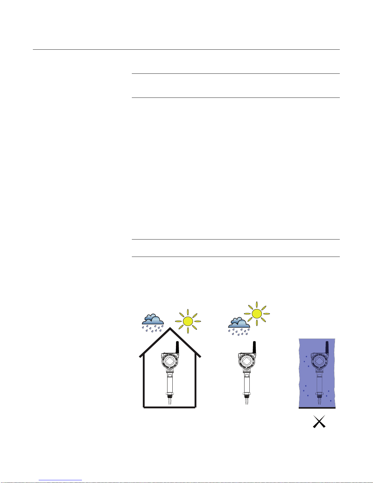
Rosemount 2160
CONSIDERATIONS
Reference Manual
00809-0100-4160, Rev AB
March 2010
General
Considerations
Wireless
Considerations
Environmental
Considerations
IMPORTANT
For material compatibility considerations, see document number
00816-0100-3045 on www.rosemount.com.
Power Up Sequence
The power module should not be installed on any wireless device until the
Smart Wireless Gateway (“Gateway”) is installed and is functioning properly.
Wireless devices should also be powered up in order of proximity to the
Gateway, beginning with the closest. This will result in a simpler and faster
network installation. Enable Active Advertising on the Gateway to ensure that
new devices join the network faster. For more information, see the
Smart Wireless Gateway Manual (Document Number 00809-0200-4420).
Antenna Position
The antenna should be positioned vertically, either straight up or straight
down, and it should be approximately 3 ft. (1 m) from any large structure,
building, or conductive surface to allow for clear communication to other
devices.
The Rosemount 2160 is a wireless liquid level switch, and is Intrinsically Safe
(IS) approved for hazardous area installations.
NOTE:
Approvals are listed in Section B of this reference manual.
Figure 3-1.
Environmental Considerations
This wireless liquid level switch is designed for open or closed t anks, and pipe
installation. It is weatherproof and protected against the ingress of dust, but
must be protected from flooding. Avoid installing the 2160 near heat sources.
OKOK
3-2
Page 45
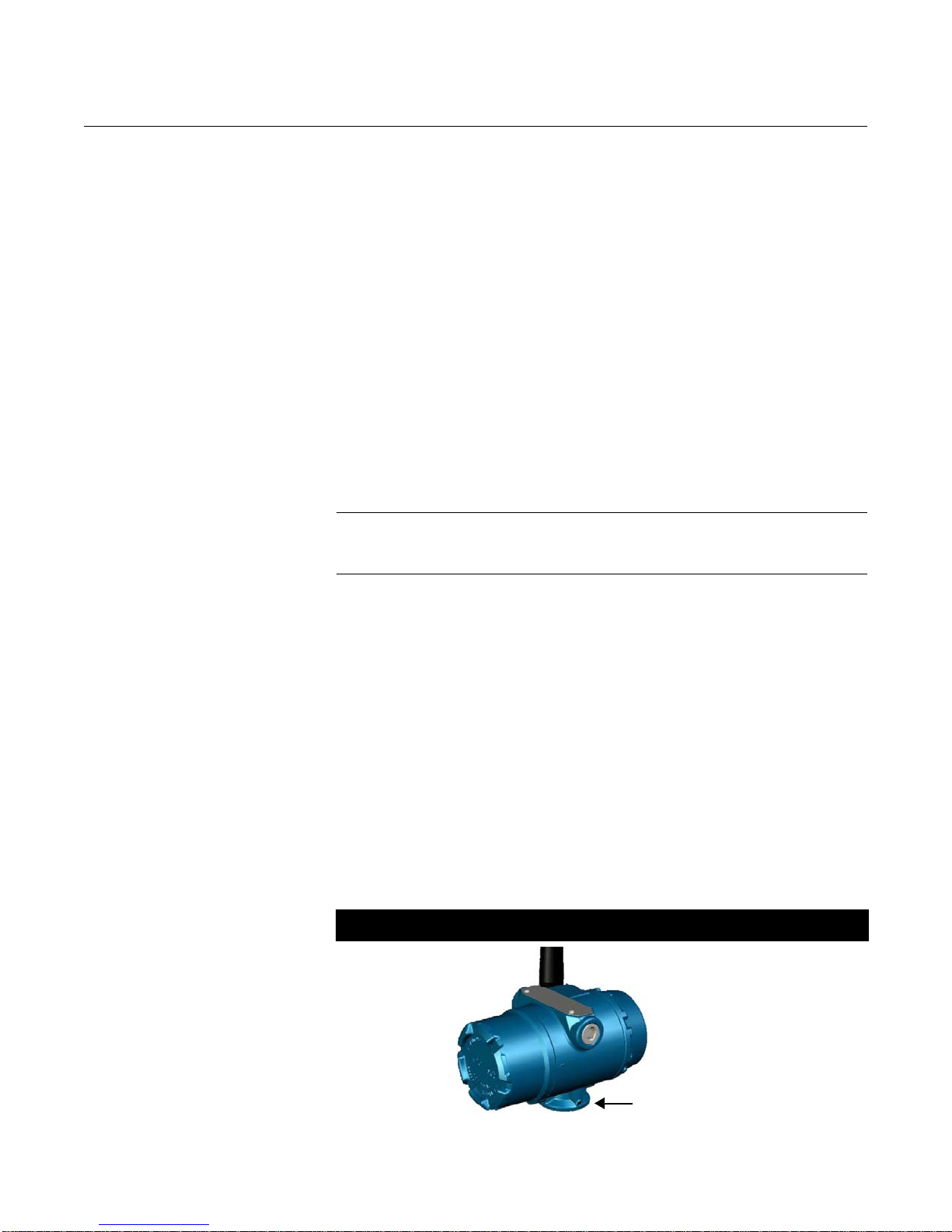
Reference Manual
Housing Rotation Set Screw
(3/32-inch allen)
00809-0100-4160, Rev AB
March 2010
Rosemount 2160
Installation
Considerations
For dimensional drawings, see “Dimensional Drawings” on page A-6.
Battery Side of Electronics Housing
Mount the switch so that the battery side is accessible. Clearance of
3
/8 in. (60 mm) is required for cover removal.
2
Circuit Side of Electronics Housing
Provide 0.75 in. (19 mm) of clearance for units without an LCD display. Three
inches of clearance is required for cover removal if a LCD display is installed.
Cover Installation
Always ensure a proper seal by installing the electronics housing cover(s) so
that metal contacts metal. Use Rosemount O-rings.
LCD Rotation
In addition to housing rotation, the optional LCD display can be rotated in 90°
increments by squeezing the two tabs, pulling out, rotating and snapping back
into place.
NOTE
If LCD pins are inadvertently removed from the interface board, carefully
re-insert the pins before snapping the LCD display back into place.
Grounding
Figure 3-2.
Housing Rotation Screw
Always ground the housing in accordance with national and local electrical
codes. The most effective grounding method for the housing is a direct
connection to earth ground with minimal impedance.
Housing Rotation
The housing can be rotated for optimal viewing of the optional LCD display
and to get the best antenna position. Perform the following procedure:
1. Loosen the housing rotation set screw (Figure 3-2).
2. First rotate the housing clockwise to the desired location. If the desired
location cannot be achieved due to thread limit (up to 360°), rotate the
housing counter-clockwise to the desired loca tio n. Do not over twist.
3. Re-tighten the housing rotation set screw.
Wireless PlantWeb Housing
3-3
Page 46
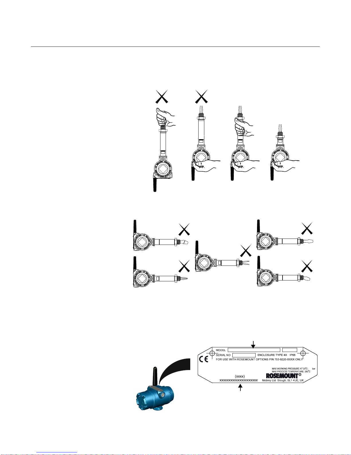
Rosemount 2160
OK OK
Factor Identifier (xxxx)
Country of Origin xxxxxxxxxxxxxxxxxxxxxxxx
Model e.g. 2160 X D 8 E S 1 NN N M0150 1 NA WA3 WK1 M5
(See “Ordering Information” on page A-13)
Figure 3-3. Handling The 2160
Reference Manual
00809-0100-4160, Rev AB
March 2010
Handling The 2160
Use both hands to carry the 2160***E and do not hold using the forks.
Figure 3-4.
Do Not Alter The 2160
Figure 3-5. Device Identification
Do not alter the 2160 in any way.
Device Identification
See Appendix B: Product Certifications for device approvals.
3-4
Page 47

Reference Manual
00809-0100-4160, Rev AB
March 2010
Rosemount 2160
Recommendations
• Avoid installing near to liquid entering the tank at the fill point
• Avoid heavy splashing on the forks
Increasing the sensor output delay reduces accidental switching
caused by splashing (see “Sensor Outp ut Delay ” on page 2-9).
• Ensure that the forks do not come into contact with the tank wall, any
internal fittings, or obstructions
• Ensure there is sufficient distance between build-up on the tank wall
and the fork (see Figure 1-2 on page 1-5)
• Ensure the installation does not create tank crevices around the forks
where liquid may collect. This can happen with high viscosity and high
density liquids
• Extra consideration is needed if the plant vibration is close to the
1300 Hz operating frequency of the 2160
• Supporting the fork avoids long fork length vibration
3-5
Page 48
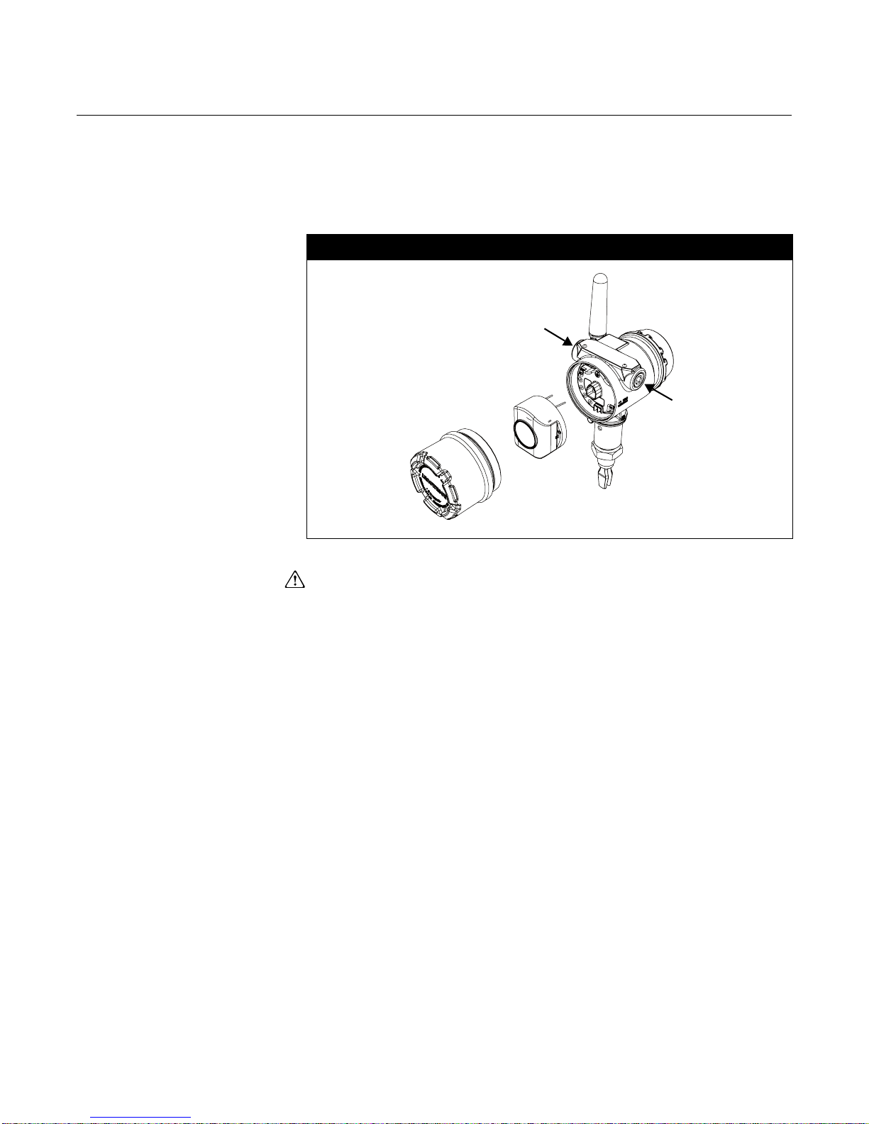
Rosemount 2160
Battery
Battery
Cover
Conduit
Connection
Conduit
Connection
INSTALLATION
PROCEDURES
Battery Installation
Figure 3-6.
Wireless Battery Installation
Reference Manual
00809-0100-4160, Rev AB
March 2010
Wireless Battery Installation
To install the battery, perform the following procedure:
1. Remove the housing cover on the battery compartment side (Figure 3-6.)
The battery supplies all power to the 2160.
2. Connect the battery.
3. Replace the battery cover and tighten to safety specification
(metal-to-metal.)
3-6
Page 49
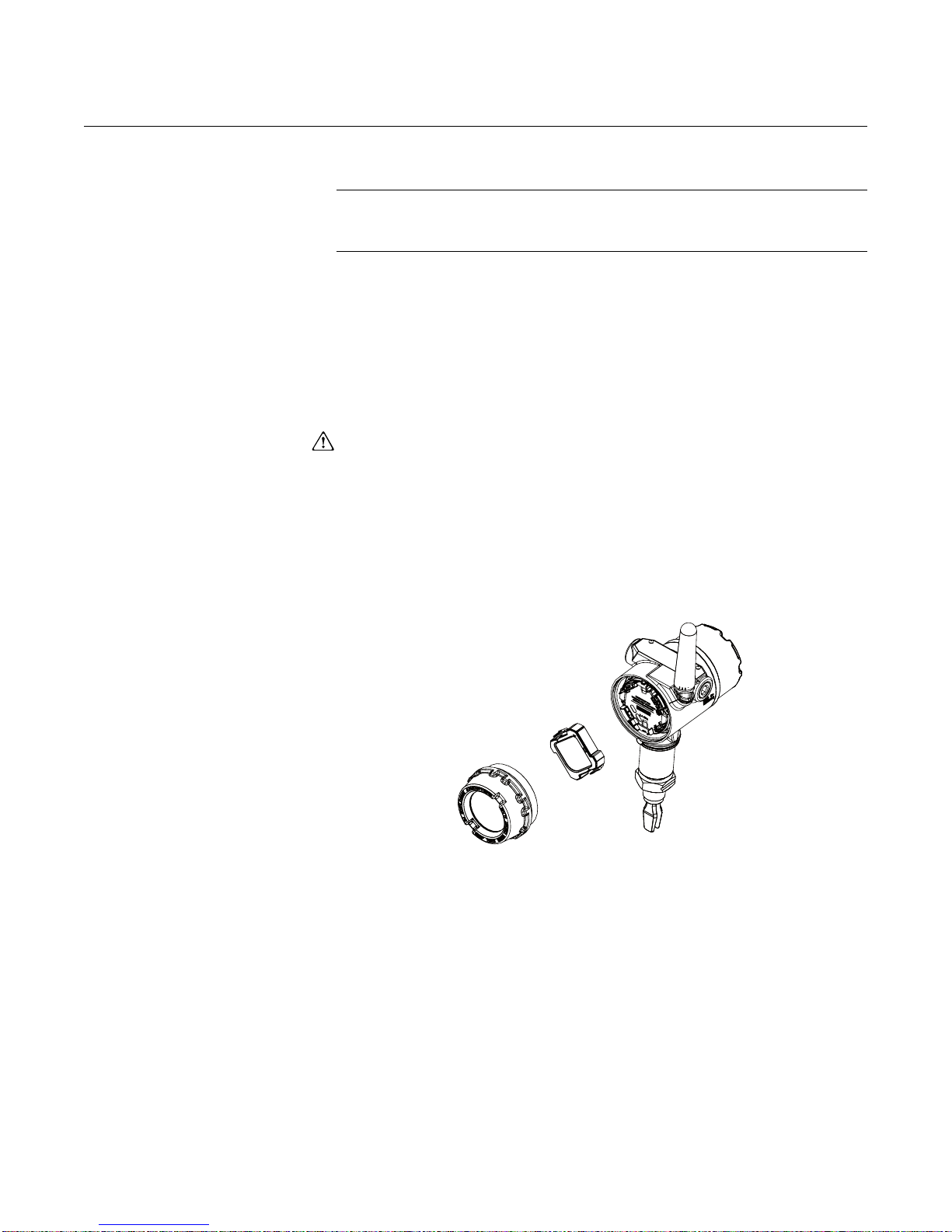
Reference Manual
LCD
Display
Meter
Cover
00809-0100-4160, Rev AB
March 2010
Rosemount 2160
Installing the
LCD Display
Figure 3-7.
Optional LCD Display
Switches ordered with the LCD display are shipped with the display installed.
NOTE
An LCD from a wired device will not function in a wireless device.
Only use Rosemount Wireless LCD Part Number: 00753-9004-0002
In addition to housing rotation, the optional LCD display can be rotated in 90°
increments by squeezing the two tabs, pulling out, rotating and snapping back
into place.
If LCD pins are inadvertently removed from the interface board, carefully
re-insert the pins before snapping the LCD display back into place.
Use the following procedure and Figure 3-7 to install the LCD display:
1. Remove the battery cover and battery (Figure 3-6.)
2. Remove the cover opposite the field terminal side. Do not remove the
covers in hazardous environments when the circuit is live.
3. Engage the four-pin connector into the LCD display and snap into place.
Note the following LCD temperature limits:
• Operating: –40 to 175 °F (–20 to 80 °C)
• Storage: –40 to 185 °F (–40 to 85 °C)
3-7
Page 50
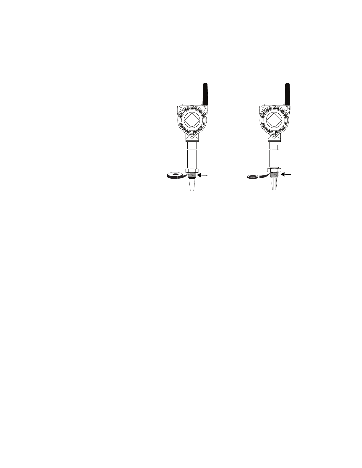
Rosemount 2160
PTFE (Teflon)
Gasket
NPT,
BSPT (R)
Thread
BSPP (G)
Thread
Mechanical Sealing
Figure 3-8. Sealing
Reference Manual
00809-0100-4160, Rev AB
March 2010
3-8
Page 51
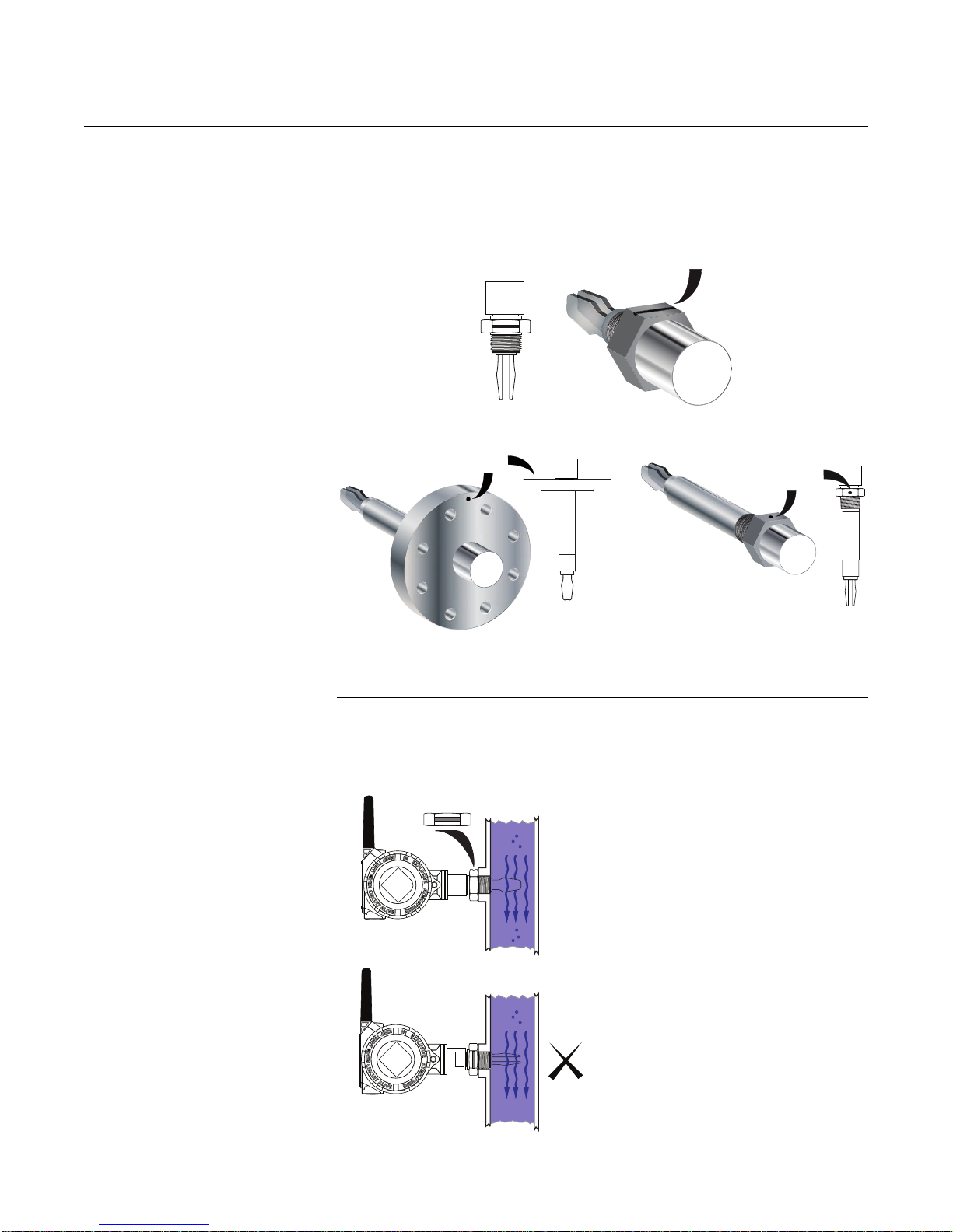
Reference Manual
Alignment Groove On
Standard Length 2160
Alignment Notch
On Flanged 2160
Alignment Notch
On Extended
Length 2160
OK
00809-0100-4160, Rev AB
March 2010
Rosemount 2160
Correct Fork Alignment Ensure the fork is correctly aligned by using the notches and grooves as
indicated in Figure 3-9.
Figure 3-9.
Correct Fork Alignment
Figure 3-10. Pipe Installation
Pipe Installation
NOTE
The housing and antenna have been rotated for an optimal viewing position
and strongest wireless signal. See “Housing Rotation” on page 3-3.
3-9
Page 52
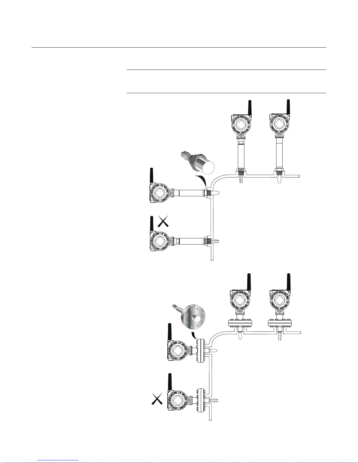
Rosemount 2160
OK OK
OK
Reference Manual
00809-0100-4160, Rev AB
March 2010
Tank Installation
Figure 3-11. Tank Installation
NOTE
The housing and antenna have been rotated for an optimal viewing position
and strongest wireless signal. See “Housing Rotation” on page 3-3.
OK OK
OK
3-10
Page 53
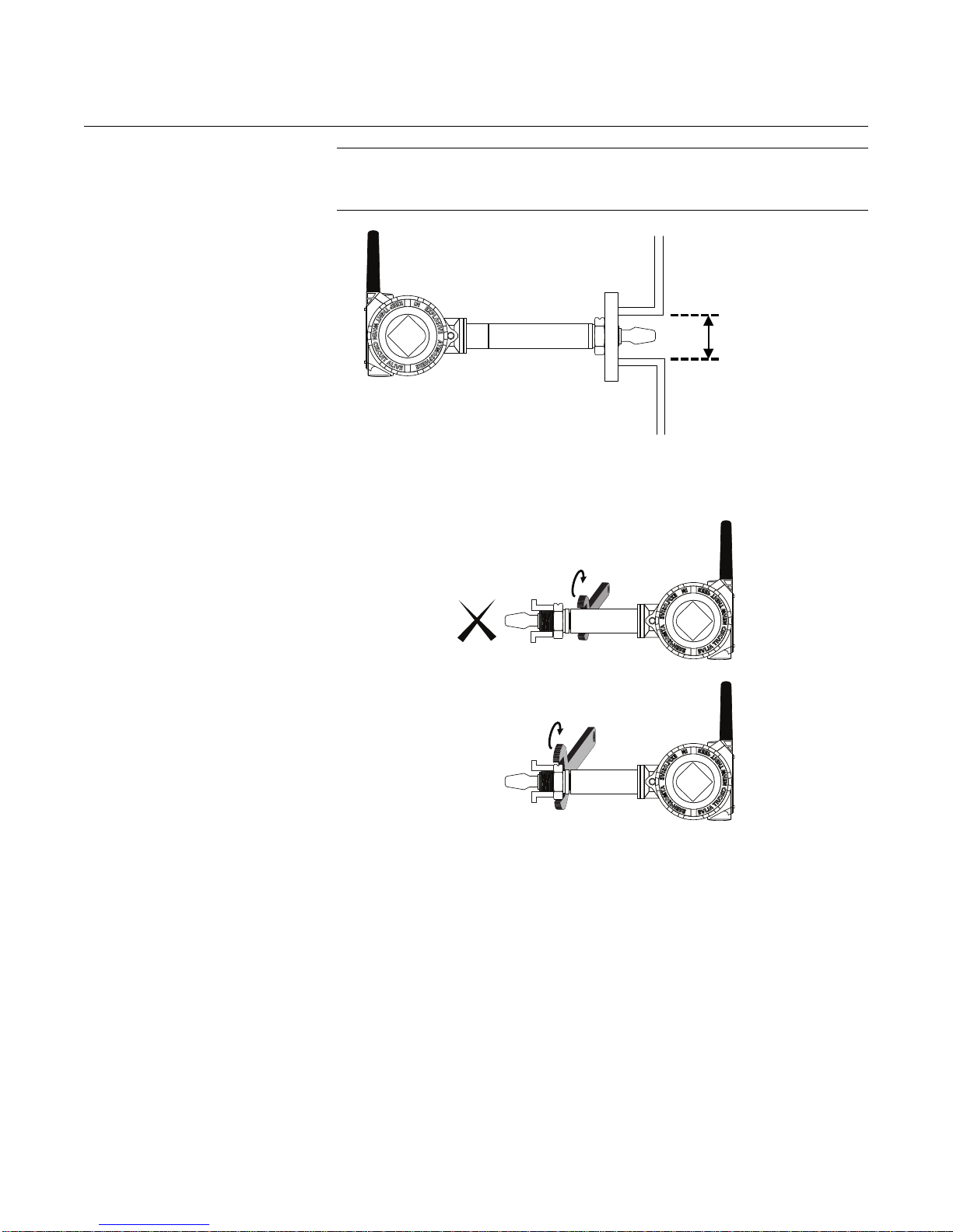
Reference Manual
Minimum Nozzle
Diameter is
3.5 in. (85 mm)
OK
00809-0100-4160, Rev AB
March 2010
Rosemount 2160
Figure 3-12.
Minimum Nozzle Diameter
Tightening the 2160
Figure 3-13.
Tightening the 2160
NOTE
The housing and antenna have been rotated for an optimal viewing position
and strongest wireless signal. See “Housing Rotation” on page 3-3.
3-11
Page 54
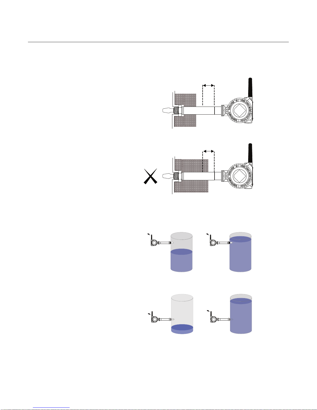
Rosemount 2160
2.1 in. (55 mm)
2.1 in. (55 mm)
Dry (0.0)
Wet (1.0)
Dry (0.0)
Wet (1.0)
Insulation
(2160***E Only)
Figure 3-14. Insulation
Reference Manual
00809-0100-4160, Rev AB
March 2010
OK
Operations
Figure 3-15. High Level Alarm
Figure 3-16. Low Level Alarm
3-12
Page 55
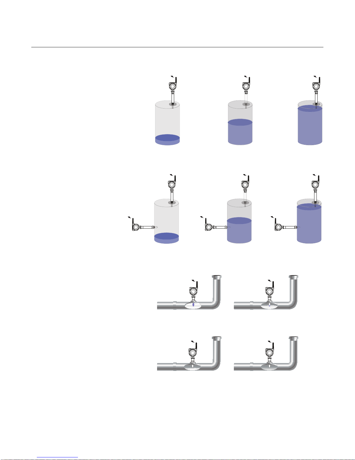
Reference Manual
00809-0100-4160, Rev AB
March 2010
Figure 3-17. Overfill Protection
Rosemount 2160
Figure 3-18. Pump Control
Dry (0.0)
Dry (0.0)
Dry (0.0)
Wet (1.0)
Dry (0.0)
Dry (0.0)
Wet (1.0)
Wet (1.0)
Wet (1.0)
Figure 3-19. Pump or Empty
Pipe Protection
Wet (1.0)
Dry (0.0)
Wet (1.0)
Dry (0.0)
3-13
Page 56

Rosemount 2160
Reference Manual
00809-0100-4160, Rev AB
March 2010
3-14
Page 57
Reference Manual
00809-0100-4160, Rev AB
March 2010
Rosemount 2160
Section 4 Commissioning
Safety Messages . . . . . . . . . . . . . . . . . . . . . . . . . . . . . . . . . page 4-1
Verify Operation . . . . . . . . . . . . . . . . . . . . . . . . . . . . . . . . . page 4-2
AMS Wireless Configurator . . . . . . . . . . . . . . . . . . . . . . . . page 4-3
SAFETY MESSAGES Instructions and procedures in this section may require special precautions to
ensure the safety of the personnel performing the operations. Information that
potentially raises safety issues is indicated by a warning symbol ( ). Please
refer to the following safety messages before performing an operation
preceded by this symbol.
Warnings
Failure to follow these installation guidelines could result in death or serious injury
• The Rosemount 2160 is a wireless liquid level switch. It must be installed, connected,
commissioned, operated, and maintained by suitably qualified personnel only,
observing any national and local requirements that may apply
• Use the equipment only as specified in this manual. Failure to do so may impair the
protection provided by the equipment
Explosions could result in death or serious injury
• Installation of the 2160 in a hazardous environment must be in accordance with the
appropriate local, national, and international standards, codes, and practices.
Please review the approvals section of the 2160 Reference Manual for any restrictions
associated with an installation
• Before connecting a Field Communicator in an explosive atmosphere, ensure the
installation is in accordance with intrinsically safe or non-incendive field wiring practices
• Verify that the operating atmosphere of the level switch is consistent with the
appropriate hazardous locations certifications
External Surface may be hot
• Care must be taken to avoid possible burns
Process leaks could result in death or serious injury
• Install and tighten process connectors before applying pressure
• Do not attempt to loosen or remove process connectors while the 2160 is in service
Electrical shock could cause death or serious injury
• If the liquid level switch is installed in a high voltage environment and a fault condition or
installation error occurs, high voltage may be present on leads and terminals
• Use extreme caution when making contact with the leads and terminals
• Make sure that power to the 2160 is off while making connections
www.rosemount.com
Page 58
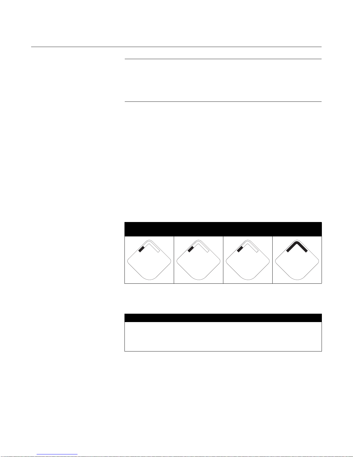
Reference Manual
00809-0100-4160, Rev AB
Rosemount 2160
March 2010
NOTE
The Rosemount 2160 and all other wireless devices should be installed only
after the Smart Wireless Gateway has been installed and is functioning
properly. Wireless devices should also be powered up in order of proximity
from the Gateway, beginning with the closest device to the Gateway. This will
result in a simpler and faster network installation.
V E RIFY OPERATION Operation can be verified in four location s: at the device via the LCD, by using
the Field Communicator, at the Smart Wireless Gateway’s integrated web
interface, or via AMS Wireless Configurator.
Troubleshooting
If the device is not joined to the network after power up, verify the correct
configuration of the Network ID and Join Key , and verify the Active Advertisin g
has been enabled on the Gateway. The Network ID and Join Key in the
device must match the Network ID and Join Key of the Gateway.
Local Display
The LCD displays the Primary Variable (PV) value at the configured update
rate, but no faster than once very 60 seconds. See Network Diagnostic Status
Screens on page 5-5 for error codes and other LCD messages. Press the
Diagnostic button to display the TAG, Device ID, Network ID, Network
Status, and Device Status screens.
Searching for
Network
n e t w k
s r c h N G
Joining
Network
n e t w k
N E G O T
Connected with
Limited Bandwidth
n e t w k
L I M _ o p
Connected
n e t w k
O K
Field Communicator
A 2160 DD (Device Descriptor) is required for HART communication.
For connecting with a Field Communicator, see Figure 2-1 on page 2-4.
Function Key Sequence Menu Items
Communications 3, 3 Join Status, Wireless Mode, Join
Mode, Number of Available
Neighbors, Number of
Advertisements Heard, and Number
of Join Attempts
Smart Wireless Gateway
4-2
In the integrated web interface from the Gateway, navigate to the
Explorer>Status page. This page will show whether the device has joined
the network and if it is communicating properly.
Page 59
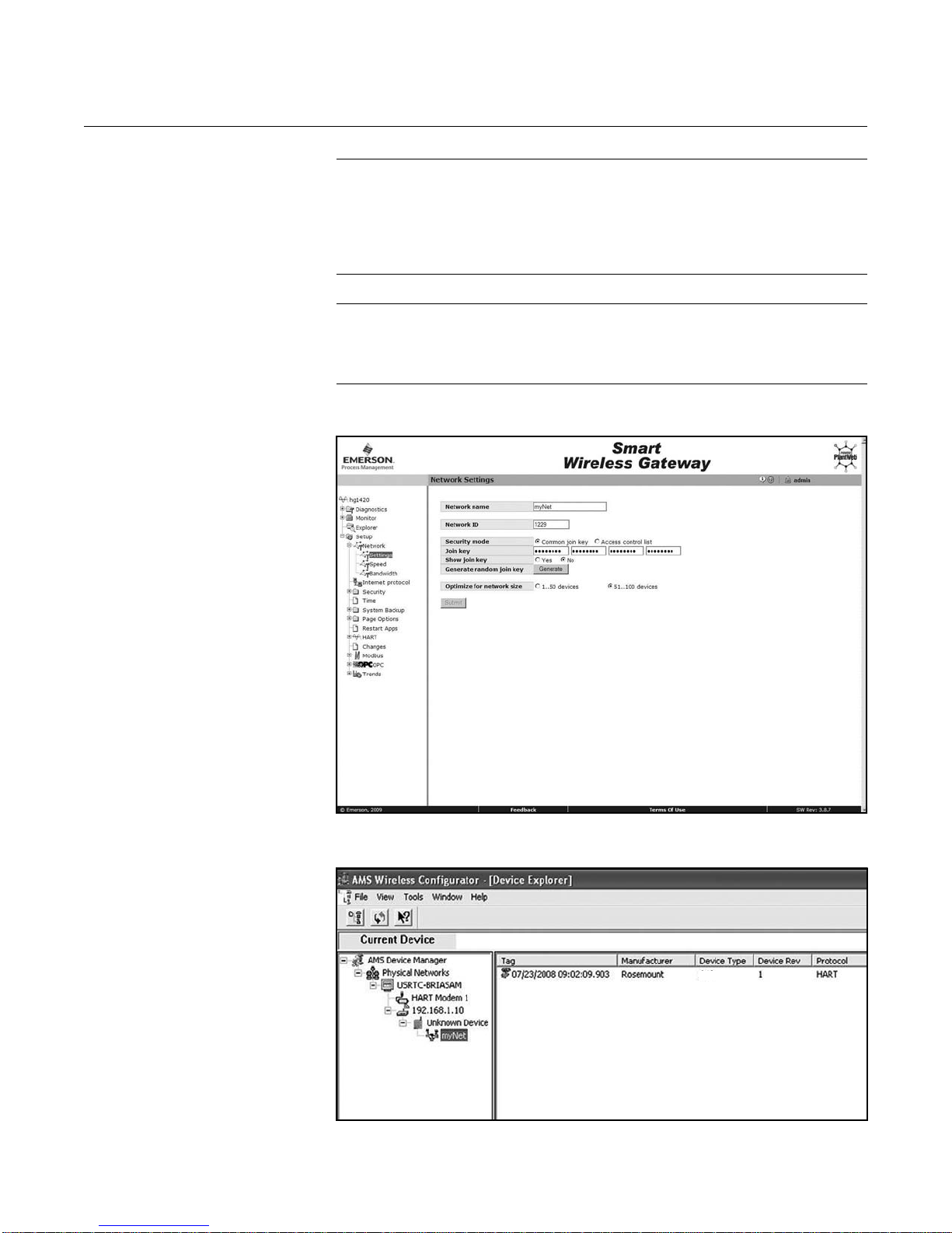
Reference Manual
2160
00809-0100-4160, Rev AB
March 2010
Figure 4-1. Smart Wireless
Gateway Network Settings
Rosemount 2160
NOTE
The time to join the new device(s) to the network is dependent upon the
number of devices being joined and the number of devices in the current
network. For one device joining am existing network with multiple devices, it
may take up to five minutes. It may take up to 60 minutes for multiple new
devices to join the existing network.
NOTE
If the device joins the network and immediately has an alarm present, it is
likely due to the 2160 configuration. Re-check the 2160 configuration (see
Section 2: Configuration).
AMS Wireless
Configurator
When the device has joined the network, it will appear in the Device Manager
as illustrated below.
4-3
Page 60

Rosemount 2160
Reference Manual
00809-0100-4160, Rev AB
March 2010
Troubleshooting
If the device is not joined to the network after power up, verify the correct
configuration of the Network ID and Join Key , and verify the Active Advertisin g
has been enabled on the Gateway. The Network ID and Join Key in the
device must match the Network ID and Join Key of the Gateway.
The Network ID and Join Key may be obtained from the Gateway on the
Setup>Network>Settings page on the web interface (see Figure 4-1 on
page 4-3). The Network ID and Join Key may be changed in the wire les s
device by using the following Fast Key sequence.
Function Key Sequence Menu Items
Wireless 2, 1, 1 Join Device to Network
4-4
Page 61
Reference Manual
00809-0100-4160, Rev AB
March 2010
Rosemount 2160
Section 5 Operation and Maintenance
Safety Messages . . . . . . . . . . . . . . . . . . . . . . . . . . . . . . . . . page 5-1
Inspection . . . . . . . . . . . . . . . . . . . . . . . . . . . . . . . . . . . . . . page 5-2
Maintenance . . . . . . . . . . . . . . . . . . . . . . . . . . . . . . . . . . . . page 5-2
LCD Screen Messages . . . . . . . . . . . . . . . . . . . . . . . . . . . . page 5-3
SAFETY MESSAGES Instructions and procedures in this section may require special precautions to
ensure the safety of the personnel performing the operations. Information that
potentially raises safety issues is indicated by a warning symbol ( ). Please
refer to the following safety messages before performing an operation
preceded by this symbol.
Warnings
Failure to follow these installation guidelines could result in death or serious injury
• The Rosemount 2160 is a wireless liquid level switch. It must be installed, connected,
commissioned, operated, and maintained by suitably qualified personnel only,
observing any national and local requirements that may apply
• Use the equipment only as specified in this manual. Failure to do so may impair the
protection provided by the equipment
Explosions could result in death or serious injury
• Installation of the 2160 in a hazardous environment must be in accordance with the
appropriate local, national, and international standards, codes, and practices.
Please review the approvals section of the 2160 Reference Manual for any restrictions
associated with an installation
• Before connecting a Field Communicator in an explosive atmosphere, ensure the
installation is in accordance with intrinsically safe or non-incendive field wiring practices
• Verify that the operating atmosphere of the level switch is consistent with the
appropriate hazardous locations certifications
External Surface may be hot
• Care must be taken to avoid possible burns
Process leaks could result in death or serious injury
• Install and tighten process connectors before applying pressure
• Do not attempt to loosen or remove process connectors while the 2160 is in service
Electrical shock could cause death or serious injury
• If the liquid level switch is installed in a high voltage environment and a fault condition or
installation error occurs, high voltage may be present on leads and terminals
• Use extreme caution when making contact with the leads and terminals
• Make sure that power to the 2160 is off while making connections
www.rosemount.com
Page 62
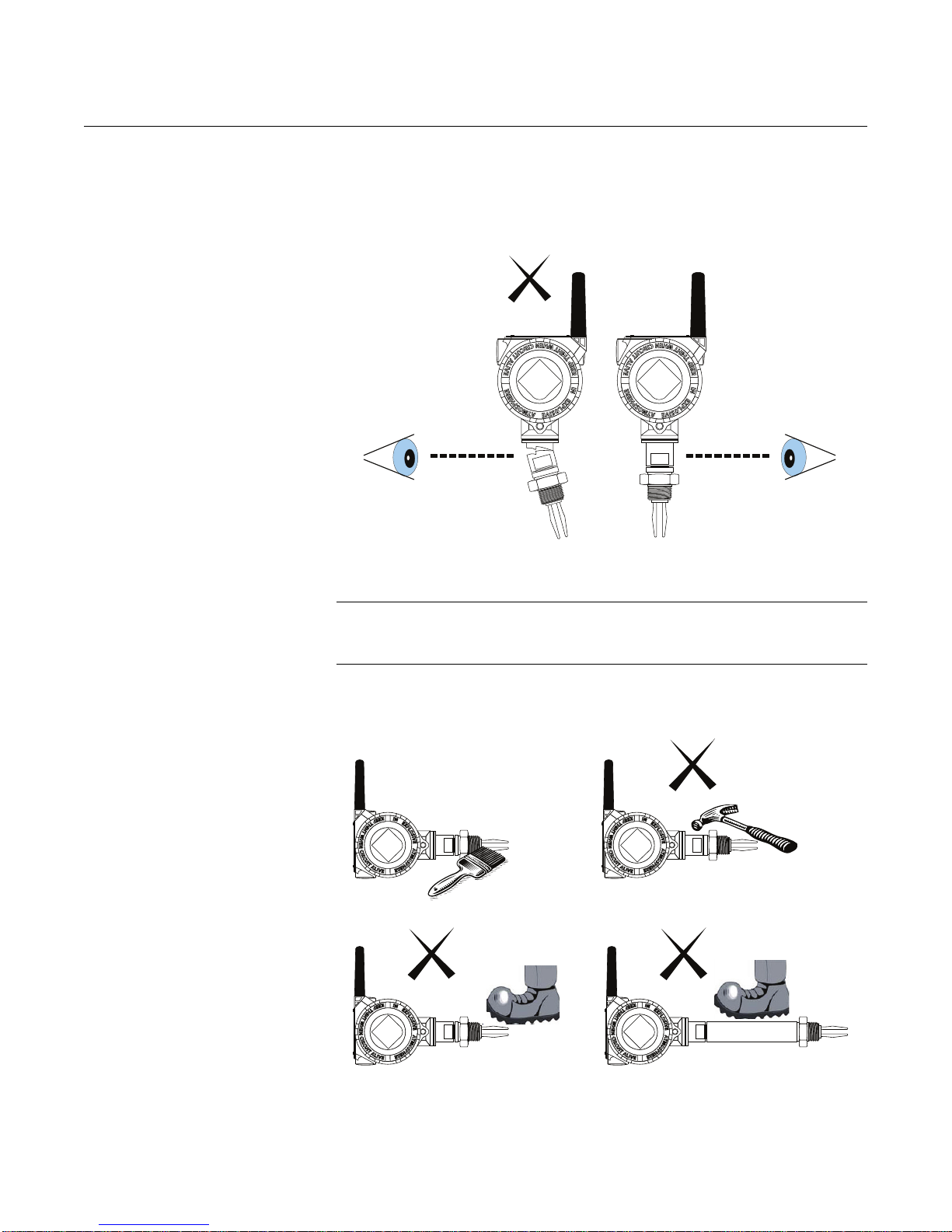
Reference Manual
OK
00809-0100-4160, Rev AB
Rosemount 2160
INSPECTION • Visually examine the 2160 for damage. If it is damaged, do not use.
• Ensure the covers, blanking plugs, and antenna are fitted securely
Figure 5-1.
Inspect the 2160 for Damage
March 2010
MAINTENANCE NOTE:
Only use a soft brush to clean the 2160. Use great care when cleaning the
forks.
Figure 5-2.
Maintenance of the 2160
OK
5-2
Page 63

Reference Manual
2 1 6 0
W I r e l s
A b c d e
f g h
F O R K
w e t
1 . 0
00809-0100-4160, Rev AB
March 2010
LCD SCREEN
MESSAGES
Rosemount 2160
Startup Screen
Sequence
The following screens will display when the battery is first connected to the
Rosemount 2160.
X X X X X
X X X X x x x
x x x x x x
All Segments On: used to visually determine if
there are any bad segments on the LCD
Device Identification: used to determine Device
Type.
Device Information - Tag: user entered tag which
is 8 characters long - will not display if all characters
are blank
PV Screen - Fork (Switch) State
5-3
Page 64

Rosemount 2160
F R E Q
1 3 5 0. 0
h Z
T E M P
2 5. 2 5
d e g c
S u p l y
7. 2 1
v o l t s
a l e r t
p r e s n t
A b c d e
f g h
Reference Manual
00809-0100-4160, Rev AB
March 2010
SV Screen - fork (switch) frequency
TV Screen - feature board temperature value
Diagnostic Button
Screen Sequence
QV Screen - battery voltage
Alert Screen - at least one alert is present - this
screen will not display if no alerts are present
The following five screens will display when the device is operating properly
and the Diagnostic Button has been pressed.
Device Information - Tag: user entered tag which
is 8 characters long - will not display if all characters
are blank
5-4
Page 65
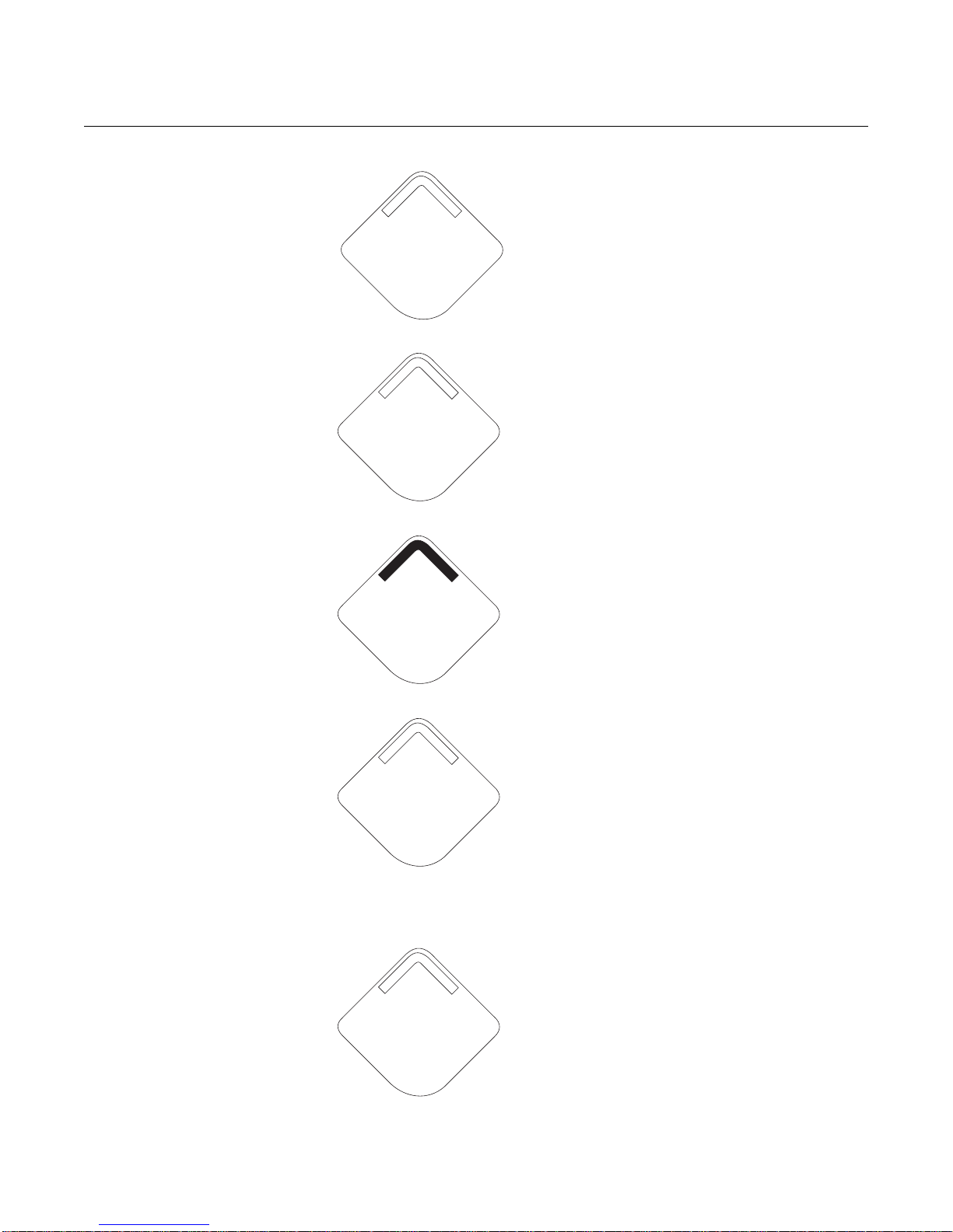
Reference Manual
n e t w k
13 0 5
I D
n e t w k
O K
S u p l y
7. 2 1
v o l t s
n e t w k
u n k n w n
00809-0100-4160, Rev AB
March 2010
i d - X X
X X X X X X
Rosemount 2160
Device Identification: used to determine Device ID
Diagnostic Button Screen 3: assuming the device
has the correct join key, this ID tells the user what
network the device can connect with
Network Diagnostic
Status Screens
Diagnostic Button Screen 4.11: the device has
joined a network and has been fully con figured and
has multiple parents
Diagnostic Button Screen 5: voltage reading at
the power supply terminals
These screens display the network status of the device. Only one will be
shown during the startup sequence or diagnostic sequence.
Diagnostic Button Screen 4.1: the device has yet
to retrieve the information from the Rosemount
1420 Wireless Gateway and is still in the process
of being activated
5-5
Page 66
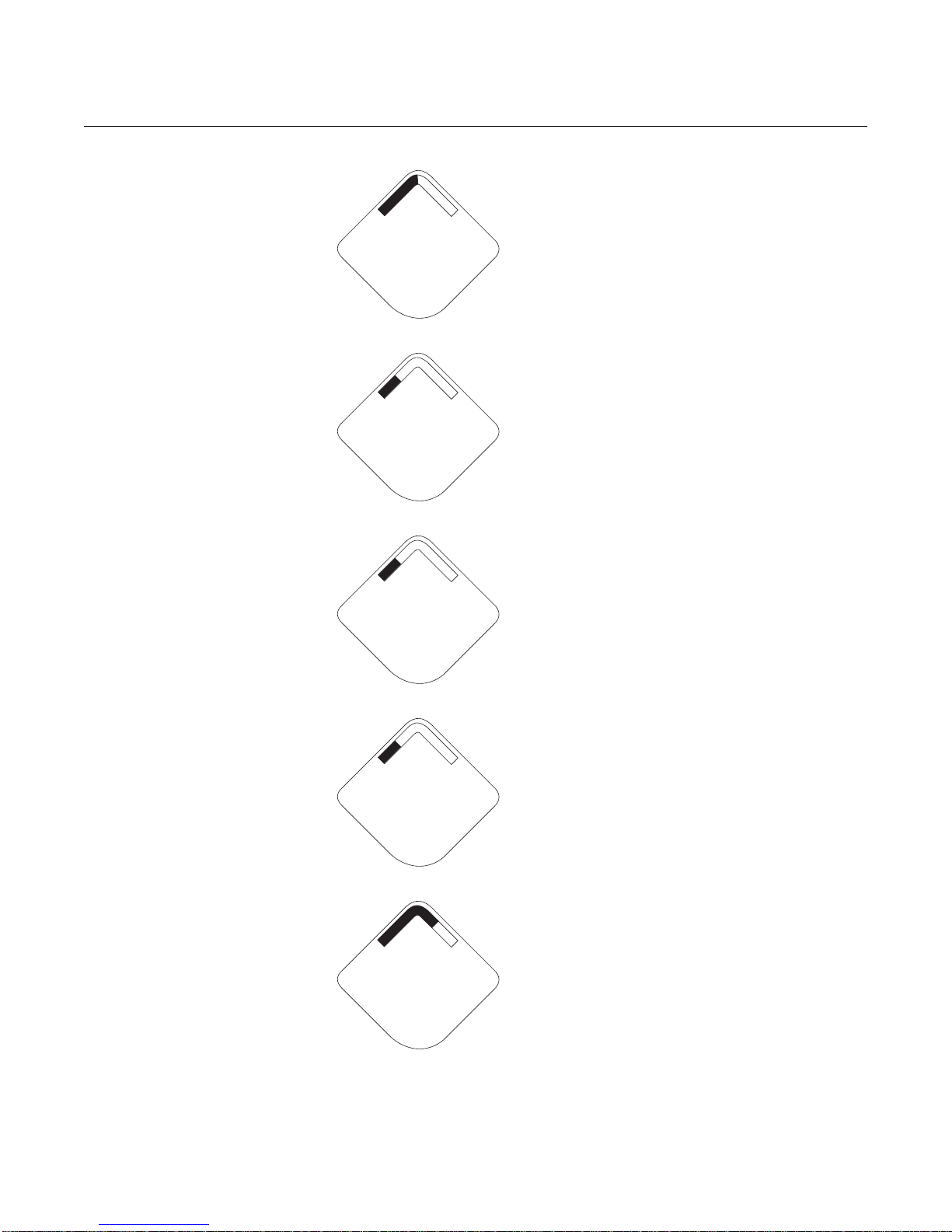
Rosemount 2160
n e t w k
j o i n g
n e t w k
a - s r c h
n e t w k
p - s r c h
n e t w k
s l e e p
n e t w k
1 p a r n t
Reference Manual
00809-0100-4160, Rev AB
March 2010
Diagnostic Button Screen 4.3: the device has
sent JOIN request and is waiting for the ACTIV ATE
command
Diagnostic Button Screen 4.4: the device is in
active search
Diagnostic Button Screen 4.5: the device is in
passive search
Diagnostic Button Screen 4.6: the device
couldn’t find the network and is in deep sleep
mode to preserve battery power
Diagnostic Button Screen 4.10: the device has
joined a network and has been fully con figured but
has only 1 parent device
5-6
Page 67

Reference Manual
D E V
f A i l u r
F O R K
w e t
1 . 0
F R E Q
1 3 5 0. 0
h Z
T E M P
2 5. 2 5
d e g c
S u p l y
7. 2 1
v o l t s
00809-0100-4160, Rev AB
March 2010
Rosemount 2160
Device Diagnostic
Screens
The following screens will show the device diagnostics depending on the state
of the device.
Device Information - Status: there is a critical error
which may prevent the device from operating
correctly. Check additional status screens for more
information.
PV Screen - fork (switch) state
SV Screen - fork (switch) frequency
TV Screen - feature board temperature value
QV Screen - battery voltage
5-7
Page 68

Rosemount 2160
a l e r t
p r e s n t
A b c d e
f g h
i d - 1 2
3 4 5 6 7 8
s u p l y
f a i l u r
s u p l y
l o w
Reference Manual
00809-0100-4160, Rev AB
March 2010
Alert Screen - at least one alert is present - this
screen will not display if no alerts are present
Diagnostic Button Screen 1 - Tag: user entered
tag which is 8 characters long - will not display if all
characters are blank
Diagnostic Button Screen 2: the device’s identifie r
that is used to make up the HART long address - the
Rosemount 1420 Wireless Gateway may use this to
help identify devices if no unique user tag is
available
Diagnostic Button Screen 7.1: the terminal
voltage has dropped below level of operating limit.
Replace the battery
(Part Number: 00753-9220-0001)
Diagnostic Button Screen 7.2: the terminal
voltage is below the recommended operating range
- if this is a battery operated device, the battery
should be replaced - for line powered devices, the
supply voltage should be increased
5-8
Page 69

Reference Manual
c o n f g
f a i l u r
c o n f g
w a r n
s n s r
f a i l u r
00809-0100-4160, Rev AB
March 2010
R A D I O
F A I L U R
Rosemount 2160
Diagnostic Button Screen 8: the device cannot
retrieve information from the radio in the device - the
device may still be operational and publishing HART
data
Diagnostic Button Screen 9.1: configuration of the
transmitter is invalid such that critical operation of
the device may be affected - check the extended
configuration status to identify which configuration
item(s) need to be corrected
Diagnostic Button Screen 9.2: configuration of the
transmitter is invalid such that non-critical operation
of the device may be affected - check the extended
configuration status to identify which configuration
item(s) need to be corrected
Diagnostic Button Screen 10.1: a sensor attached
to the liquid level switch has failed, and valid
readings from that sensor are no longer possible check the sensor and sensor wiring connections check additional status for more detailed information
of the failure source
NOTE
Use the Rosemount Wireless LCD Part Number: 00753-9004-0002.
5-9
Page 70

Rosemount 2160
Reference Manual
00809-0100-4160, Rev AB
March 2010
5-10
Page 71
Reference Manual
00809-0100-4160, Rev AB
March 2010
Rosemount 2160
Section 6 Troubleshooting
Safety Messages . . . . . . . . . . . . . . . . . . . . . . . . . . . . . . . . . page 6-1
Troubleshooting . . . . . . . . . . . . . . . . . . . . . . . . . . . . . . . . .page 6-2
Disassembly Procedures . . . . . . . . . . . . . . . . . . . . . . . . . . page 6-3
Re-assembly Procedures . . . . . . . . . . . . . . . . . . . . . . . . . . page 6-5
SAFETY MESSAGES Procedures and instructions in this section may require special precautions to
ensure the safety of the personnel performing the operations. Information that
raises potential safety issues is indicated by a warning symbol ( ). Refer to
the following safety messages before performing an operation preceded by
this symbol.
Warnings
Failure to follow these installation guidelines could result in death or serious injury
• The Rosemount 2160 is a wireless liquid level switch. It must be installed, connected,
commissioned, operated, and maintained by suitably qualified personnel only,
observing any national and local requirements that may apply
• Use the equipment only as specified in this manual. Failure to do so may impair the
protection provided by the equipment
Explosions could result in death or serious injury
• Installation of the 2160 in a hazardous environment must be in accordance with the
appropriate local, national, and international standards, codes, and practices.
Please review the approvals section of the 2160 Reference Manual for any restrictions
associated with an installation
• Before connecting a Field Communicator in an explosive atmosphere, ensure the
installation is in accordance with intrinsically safe or non-incendive field wiring
practices
• Verify that the operating atmosphere of the level switch is consistent with the
appropriate hazardous locations certifications
External Surface may be hot
• Care must be taken to avoid possible burns
Process leaks could result in death or serious injury
• Install and tighten process connectors before applying pressure
• Do not attempt to loosen or remove process connectors while the 2160 is in service
Electrical shock could cause death or serious injury
• If the liquid level switch is installed in a high voltage environment and a fault condition
or installation error occurs, high voltage may be present on leads and terminals
• Use extreme caution when making contact with the leads and terminals
• Make sure that power to the 2160 is off while making connections
www.rosemount.com
Page 72

Reference Manual
00809-0100-4160, Rev AB
Rosemount 2160
TROUBLESHOOTING See Table 6-1 for the Rosemount 2160 troubleshooting table.
Table 6-1. Rosemount 2160 troubleshooting table
Symptom Corrective Actions
LCD is not functioning
Does not switch output state
Incorrect switching of output state
Faulty switching of output state
PV Status = Fault
• Re-seat the LCD according to “Installing the LCD Display” on page 3-7
• Verify that the LCD is a wireless LCD (Rosemount part number: 00753-9004-0002).
An LCD from a wired device will not function in a wireless device
• Verify that the LCD display mode is not disabled (Fast Key sequence 2, 2, 5, 1)
• There is no power – check the battery is installed correctly. Try another battery.
• Fork is damaged – replace the 2160
• Thick encrustation on the forks – clean the fork with care
• Check the configuration of frequency bands
(See “Dry Fork Frequency / Switch Points” on page 2-18)
• Turbulence – set a longer switching time delay
(See “Sensor Output Delay” on page 2-9)
• Excessive electrical noise – suppress the cause of the interference
• The sensor state is Too Dry, Too Wet, or Zero – enhanced mode only.
(See “Dry Fork Frequency / Switch Points” on page 2-18).
March 2010
6-2
Page 73
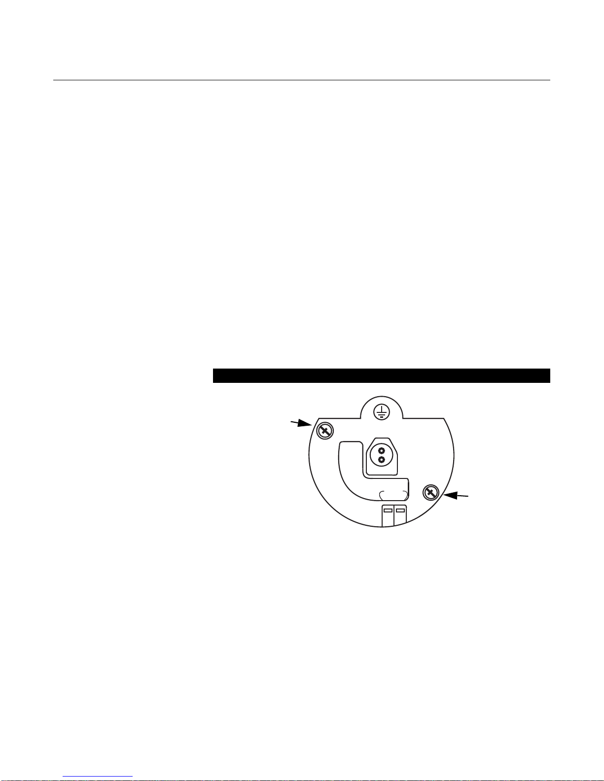
Reference Manual
00809-0100-4160, Rev AB
March 2010
DISASSEMBLY
PROCEDURES
Remove from Service Be aware of the following:
• Follow all plant safety rules and procedures.
• Isolate and vent the process before removing the 2160 from service.
• Whenever you remove the 2160, visually inspect the o-rings (if used).
Replace the o-rings if they show any signs of damage, su ch as nicks or
cuts. If they are not damaged, re-use them.
The flanged 2160 is attached to the process conn ection by bolt s. Remove the
bolts and separate the switch from the pr ocess connection. Leave the process
connection in place and ready for re-installation.
The threaded 2160 is attached to the process by a single hex nut process
connection. Loosen the hex nut to separate the switch from the process
connection. Leave the process connection in place and ready for
re-installation.
Remove Terminal Block Wireless PlantWeb Housing
Rosemount 2160
Remove the battery pack. Loosen the two small screws and pull the entire
terminal block out.
Wireless PlantWeb Terminals
P/N 00753-9200-0010
COMM
6-3
Page 74
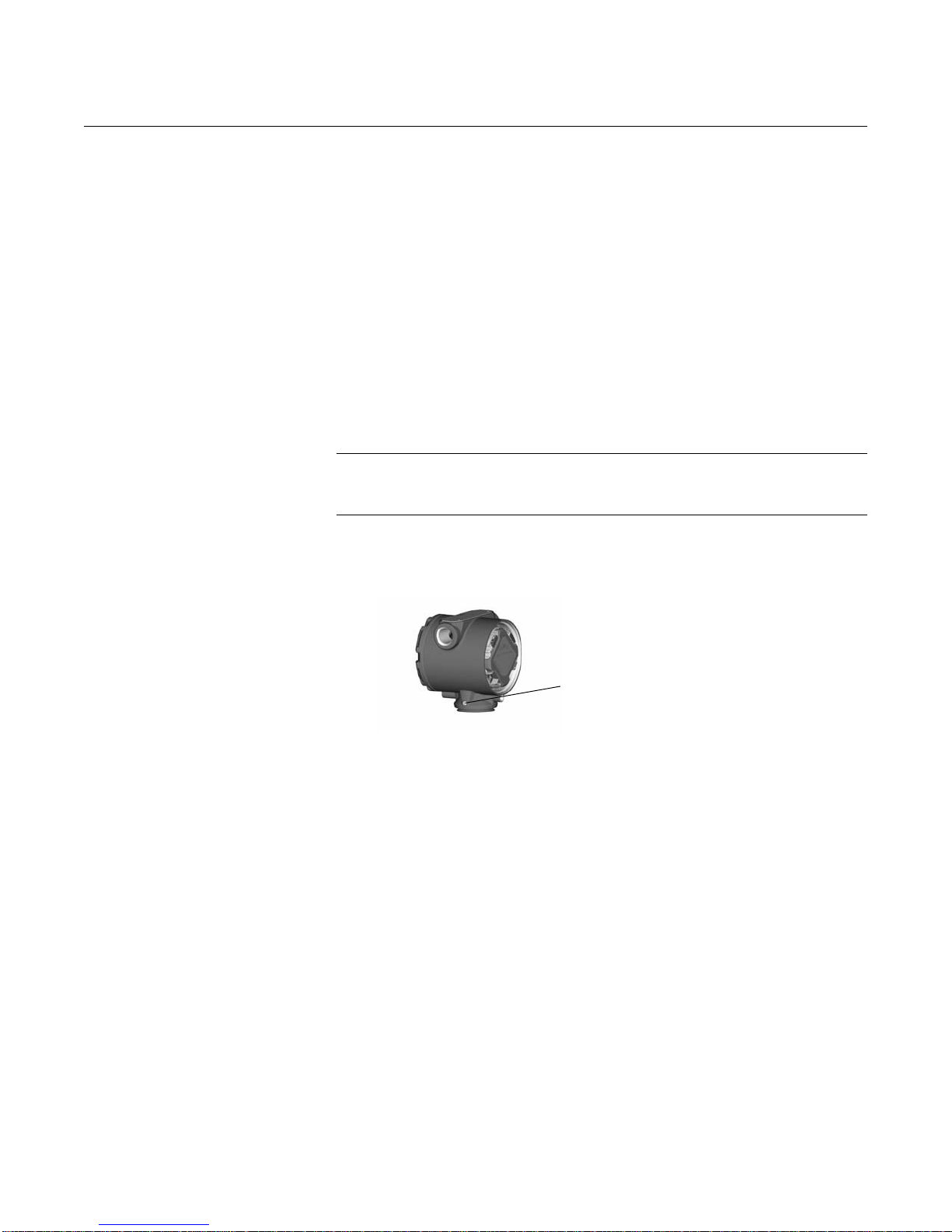
Rosemount 2160
Housing Rotation Set
Screw (3/32-inch allen)
Reference Manual
00809-0100-4160, Rev AB
March 2010
Remove Feature
Assembly
Remove the Sensor
from the Housing
The WirelessHART Feature Board is located in the electronics compartment.
To remove the assembly, perform the following procedure.
1. Remove the housing cover opposite the field terminal side.
2. Remove the LCD Display, if applicable. To do this, hold in the two clips
and pull outward.
3. Loosen the two small screws located on the assembly.
4. Replace the LCD Display. This will help in removing the assembly.
5. Pull out the assembly to expose and locate the sensor connector and
antenna connector.
6. Remove the LCD Display, if applicable. To do this, hold in the two clips
and pull outward.
7. Grasp antenna connector by the base and pull upwards to disconnect.
8. Grasp the sensor connector and pull upwards (avoid pulling wires).
IMPORTANT
To prevent damage to the sensor cable, disconnect it from the PlantWeb
assembly before you remove the sensor from the housing.
3
1. Loosen the housing rotation set screw with a
rotate back one full turn.
2. Unscrew the housing.
/32-inch hex wrench, then
6-4
Page 75

Reference Manual
00809-0100-4160, Rev AB
March 2010
Rosemount 2160
RE-ASSEMBLY
PROCEDURES
Attach the Sensor to the
Wireless Housing
IMPORTANT
The V-Seal must be installed at the bottom of the housing.
1. Insert the sensor connector into the top of the sensor.
2. Reconnect the antenna wiring.
3. Gently slide the assembly into the housing, making sure the pins from
the PlantWeb housing properly engage the recept acles on the assembly.
Avoid trapping the sensor wires.
4. Tighten the captive mounting screws.
5. Attach the PlantWeb housing cover and tighten so that metal contacts
metal.
Install the Terminal Block 1. Gently slide the terminal block into the housing, making sure the pins
from the PlantWeb housing properly engage the receptacles on the
terminal block.
2. Tighten the captive screws on the terminal block.
3. Attach the Wireless PlantWeb housing cover and tighten so that metal
contacts metal.
Re-assemble to the
Process Flange
1. Inspect the o-rings, if used. If the o-rings are not damaged, reuse them.
Replace o-rings that show any signs of damage, such as nicks, cuts, or
general wear.
NOTE
If you are replacing the o-rings, be careful not to scratch the o-ring grooves
when removing the damaged o-rings.
2. Install onto the process flange.
3. Install the appropriate flange bolts.
6-5
Page 76

Rosemount 2160
Reference Manual
00809-0100-4160, Rev AB
March 2010
6-6
Page 77

Reference Manual
00809-0100-4160, Rev AB
March 2010
Appendix A Specifications and
Reference Data
Specifications . . . . . . . . . . . . . . . . . . . . . . . . . . . . . . . . . . . page A-1
Dimensional Drawings . . . . . . . . . . . . . . . . . . . . . . . . . . . . page A-6
Ordering Information . . . . . . . . . . . . . . . . . . . . . . . . . . . . . page A-13
SPECIFICATIONS
Physical Product
The Rosemount 2160 WirelessHART
Vibrating Fork Liquid Level Switch
Measuring Principle
Vibrating Fork
Rosemount 2160
Applications
Most liquids including coating liquids, aerated liquids, and slurries.
Mechanical Enclosure
Housing:Low-copper aluminum
Paint:Polyurethane
Cover O-ring:Buna-N
Terminal Block and Power Module Pack
PBT
Antenna
PBT/PC integrated omnidirectional antenna
Process Connection
Threaded Connection:
3
R
/4 in. and 1 in. (BSPT); G 3/4 in. and 1 in. (BSPP); 3/4 in. and 1 in. NPT.
Material: 316/316L SST (1.4401/1.4404) dual certified, or Alloy C and Alloy C-276.
Accessories:
A stainless steel adjustable clamp gland is available for use with the extended length
2160 (1-in. models only). This clamp gland has a 1
connect to the tank or pipe, and allows a 1-in. extended length 2160 to be raised or
lowered, and clamped into position. See “Spare Parts and Accessories” on page A-15.
Flanged Connection:
ASME B16.5 (1-in. or larger) or EN 1092-1 (DN25 or larger)
Material: 316/316L SST (1.4401/1.4404) dual certified, or Alloy C and Alloy C-276
1
/2 in. BSPP or NPT thread to
www.rosemount.com
Page 78

Rosemount 2160
Reference Manual
00809-0100-4160, Rev AB
March 2010
Hygienic Connection (Fitting):
1
1
/2 in. (38 mm) or 2 in. (51 mm) Tri- Clamp, or 1 in. BSPP (G) O-ring seal.
Material:
316/316L SST (1.4401/1.4404) dual certified.
Gasket material for
Grade X carbon fiber with rubber binder.
Options:
Hand polished wetside to a finish better than 0.4 µm.
Accessories:
A mounting kit comprising a fitting, Nitrile seal and clamp ring is available for use with
the 2-in. (51 mm) Tri-Clamp version of the 2160.
A fitting boss with Fluorocarbon (FPM/FKM) O-ring is available for use with the O-ring
seal version of the 2160.
See “Spare Parts and Accessories” on page 15.
Fork Length
Short fork for minimum intrusion installation. The minimum length is 2 in.
3
/4 in. and 1 in. BSPP (G) O-ring seal is non-asbestos BS7531
Extended Lengths
Table A-1. Minimum Extended Lengths
Process Connection Minimum Extended Length
3
/4–in Threaded 3.8 in. (95 mm)
1–in Threaded 3.7 in. (94 mm)
Flanged 3.5 in. (89 mm)
Tri-Clamp 4.1 in. (105 mm)
The maximum extended length is 118.1 in. (3000 mm) except for:
• Hand-polished process (maximum length is 39.4 in. / 1000 mm)
Dimensional Drawings
See “Dimensional Drawings” on page A-6.
Mounting
Suitable for horizontal and vertical installations.
Rotatable housing allows correct alignment of both the forks and the omnidirectional
antenna for optimal signal and best viewing position of the LCD integral display.
Enclosure Ratings
Housing is NEMA 4X and IP66 compliant.
A-2
Page 79

Reference Manual
00809-0100-4160, Rev AB
March 2010
Electrical Wireless Power Module
Replaceable, Intrinsically Safe Lithium-Thionyl Chloride power module with PBT
enclosure.
Ten year life at one minute transmit rate
(1) Reference conditions are 70° F (21° C), and routing data for three additional network
devices. NOTE: Continuous exposure to ambient temperature limits (–40 °F or 185 °F)
(–40 °C or 85 °C) may reduce specified power module life by 20 percent.
(1)
HART Communicator Connections
Clips permanently fixed to terminal block
Performance Electromagnetic Compatibility (EMC)
All models meet all relevant requirements of EN 61326.
Hysteresis (Water)
±0.039 in. (±1 mm) nominal
Switching Point (Water)
0.5 in. (13 mm) from fork tip if mounted vertically.
0.5 in. (13 mm) from the fork edge if mounted horizontally.
The switch point varies with different liquid densities.
Rosemount 2160
Functional Output
WirelessHART 2.4 GHz DSSS
Local Display
The optional five-digit integral LCD display can indicate the switch state (Dry or Wet)
and diagnostic information.
Humidity Limits
0 to 100% relative humidity
Transmit Rate
User-selectable: from 4 seconds up to 60 minutes.
The optional integral LCD display updates at the transmit rate up to once per minute.
Operating Modes
Table A-2. Operating Modes
Fault Conditions Detected
PCB Control Circuit Corruption
External Damage to Fork
Internal Damage to Sensor
Excessive Corrosion
Over-temperature
Normal
Mode
Yes Yes
No Yes
No Yes
No Yes
No Yes
Enhanced
Mode
A-3
Page 80
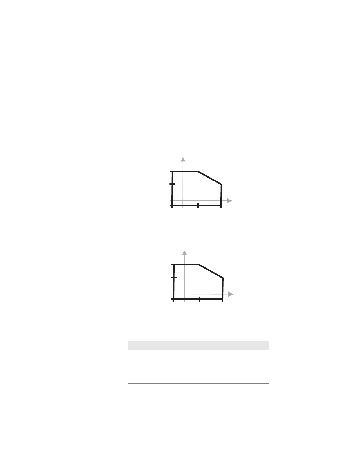
Rosemount 2160
1450 (100)
1880 (80)
-14.5 (-1.0)
-40
(-40)
122
(50)
302
(150)
Process Temperature °F (°C)
Process Pressure psig (barg)
32
(0)
2160***S
1450 (100)
885 (61)
-14.5 (-1.0)
-94
(-70)
100
(38)
500
(260)
Process Temperature °F (°C)
Process Pressure psig (barg)
32
(0)
2160***E
Reference Manual
00809-0100-4160, Rev AB
March 2010
Maximum Operating Pressure
Threaded connection: See Figure 1
Hygienic connection: 435 psig (30 bar g)
Flanged connection:
The maximum operating pressure is the lower of the process pressure (Figure 1) and
flange pressure rating (Table A-3).
NOTE
The final maximum operating pressure rating depends on the process (tank)
connection. Clamp glands (order #02120-2000-0001 or 02120-2000-0002) limit the
maximum operating pressure to 18.85 psig (1.3 bar g).
FIGURE 1. Process Pressure
A-4
Table A-3. Maximum Flange Pressure Rating
(2)
(1)
(2)
(2)
(3)
(3)
(3)
(3)
Flange Standard SST Flanges
ASME B16.5 Class 150 275 psig
ASME B16.5 Class 300 720 psig
ASME B16.5 Class 600 1,440 psig
EN1092-1 PN 10/16 9.84/15.75 bar g
EN1092-1 PN 25/40 24.6/39.4 bar g
EN1092-1 PN 64 63 bar g
EN1092-1 PN 100 98.4 bar g
(1) ASTM stainless steel.
(2) At 100 °F (38 °C), the pressure rating decreases with an
increasing process temperature.
(3) At 248 °F (120 °C), the pressure rating decreases with an
increasing process temperature.
Page 81
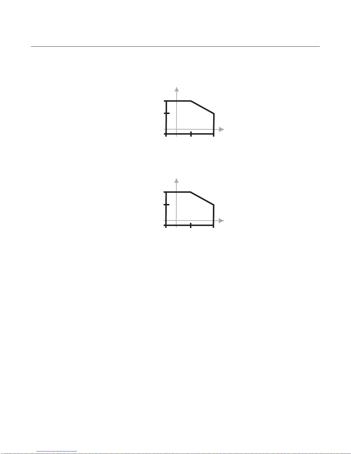
Reference Manual
176 (80)
122
(50)
-40 (-40)
-40
(-40)
302
(150)
Process Temperature °F (°C)
Ambient Temperature °F (°C)
122 (50)
32 (0)
32
(0)
2160***S
176 (80)
176
(80)
-40 (-40)
-94
(-70)
500
(260)
Process Temperature °F (°C)
Ambient Temperature °F (°C)
149 (65)
32 (0)
32
(0)
2160***E
00809-0100-4160, Rev AB
March 2010
Rosemount 2160
Temperature
See Figure 2 for th e maximum and minimum operating temperatures.
FIGURE 2. Temperature
Liquid Density Range
Minimum liquid density is 31.2 lb/ft3 (500 kg/m3).
Liquid Viscosity Range
0.2 to 10000 cP (centiPoise).
Solids Content and Coating
The maximum recommended diameter of solid particles in the liquid is 0.2 in. (5 mm).
For coating products, avoid bridging of forks (fork-to-fork).
CIP (Clean In Place) Cleaning
The Rosemount 2160 withstands steam cleaning.
A-5
Page 82
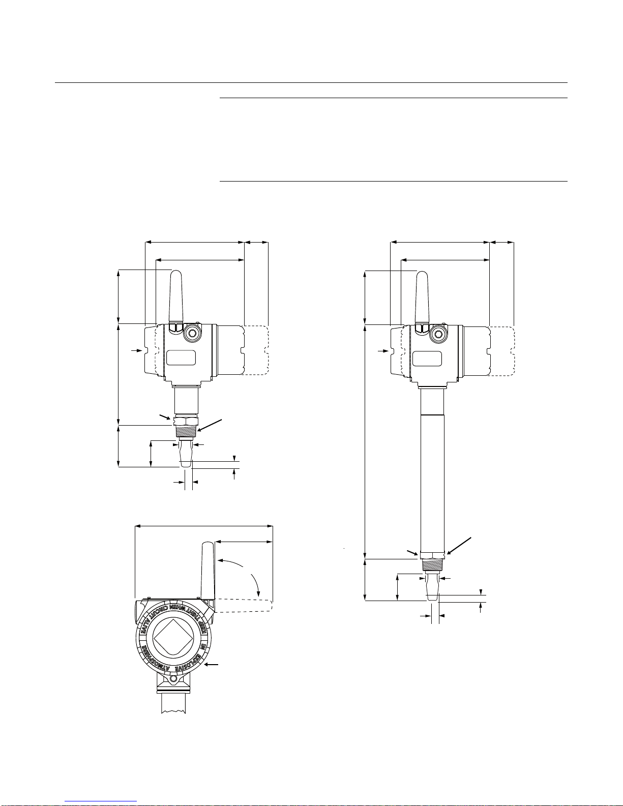
Rosemount 2160
Aluminum
Housing
0.5 (13) Switchpoint
(When Mounted Horizontally)
0.5 (13) Switchpoint
(When Mounted Vertically)
3
/4 in. or 1 in.
Thread
6.1 (154) No LCD Fitted
1.14 (29) for 1 in. Thread
0.9 (23) for
3
/4 in. Thread
1.7
(44)
2.7
(69)
Minimum
To Allow
Removal
Of Cover
View On
Arrow ‘A’
Showing
Possible
Antenna
Rotation
90°
6.9
(174)
1.6 (40) A/F
Hexagon
0.5 (13) Switchpoint
(When Mounted Horizontally)
0.5 (13) Switchpoint
(When Mounted Vertically)
3
/4 in. or 1 in. Thread
1.14 (29) for 1 in. Thread
0.9 (23) for
3
/4 in. Thread
1.7
(44)
2.7
(69)
14.5
(369)
2160***S
2160***E
3.5
(90)
3.5
(90)
7.9 (200)
6.8 (172) LCD Fitted
2.4
(60)
3.7 (93)
1.6 (40) A/F
Hexagon
6.8 (172) LCD Fitted
6.1 (154) No LCD Fitted
Minimum
To Allow
Removal
Of Cover
2.4
(60)
Reference Manual
00809-0100-4160, Rev AB
March 2010
DIMENSIONAL
DRAWINGS
2160 Thread Mounting
(Standard Length)
A
2160 Thread Mounting (Standard Length). . . . . . . . . . . . . . .page A-6
2160 Thread Mounting (Extended Length) . . . . . . . . . . . . . . page A-7
2160 Flange Mounting (Standard Length). . . . . . . . . . . . . . .page A-8
2160 Flange Mounting (Extended Length) . . . . . . . . . . . . . . page A-9
2160 Hygienic Fitting (Standard Length) . . . . . . . . . . . . . . . .page A-10
2160 Hygienic Fitting (Extended Length). . . . . . . . . . . . . . . .page A-12
Note: Dimensions are in inches (millimeters)
A
A-6
Page 83
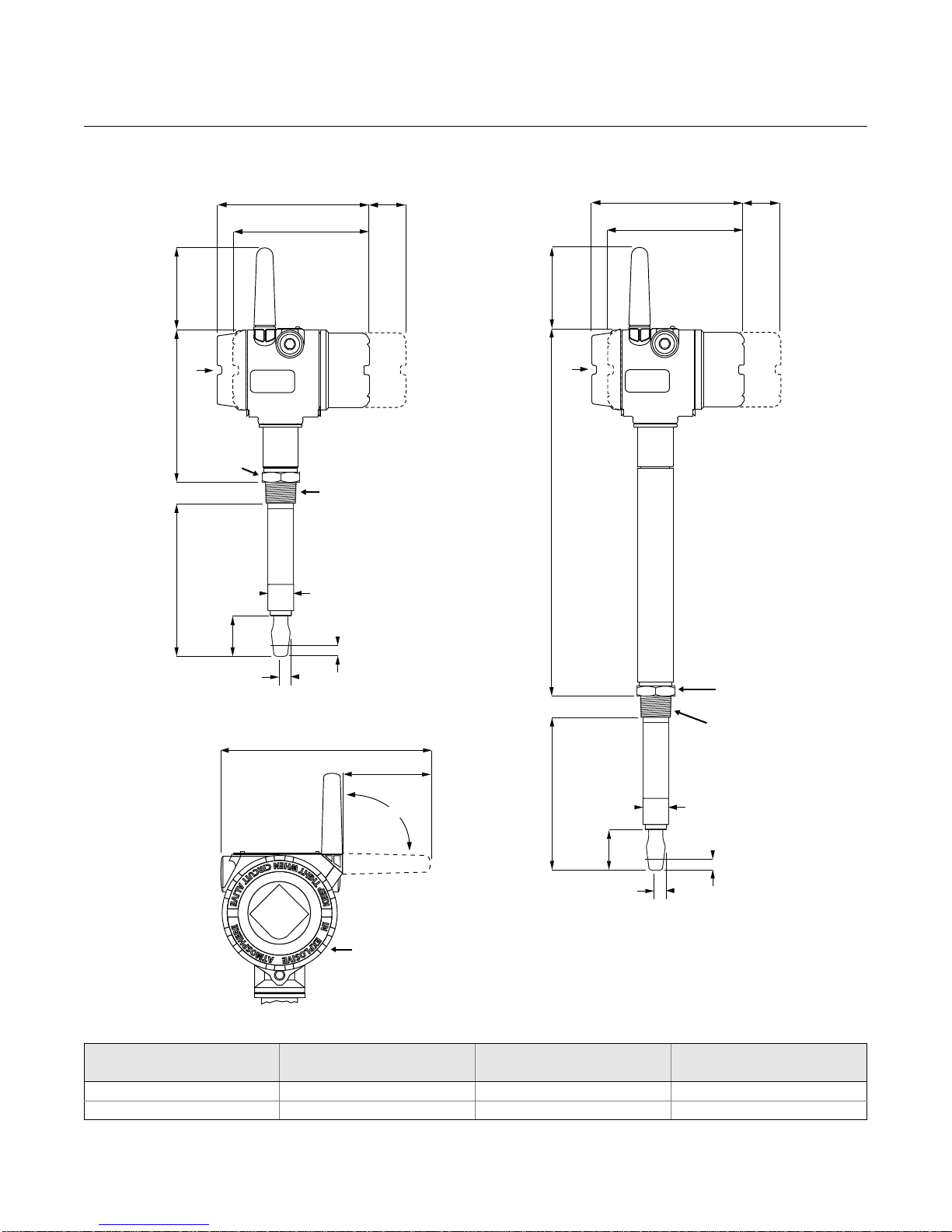
Reference Manual
A
A
1.65 (40) A/F
Hexagon
3
/4 in. or 1 in. Thread
E(M)
1.7
(44)
0.5 (13) Switchpoint
(When Mounted Horizont al ly)
0.5 (13) Switchpoint
(When Mounted Vertically)
1.14 (29) for 1 in. Thread
0.9 (23) for
3
/4 in. Thread
90°
14.4
(367)
6.8
(172)
1.6 (40) A/F
Hexagon
0.5 (13) Switchpoint
(Mounted Horizontally)
0.5 (13) Switchpoint
(When Mounted Vertically)
3
/4 in. or 1 in. Thread
1.14 (29) for 1 in. Thread
0.9 (23) for
3
/4 in. Thread
1.7
(44)
E(M)
2160***S
2160***E
3.5
(90)
3.5
(90)
6.1 (154) No LCD Fitted
Minimum
To Allow
Removal
Of Cover
6.8 (172) LCD Fitted
2.4
(60)
6.8 (172) LCD Fitted
6.1 (154) No LCD Fitted
Minimum
To Allow
Removal
Of Cover
2.4
(60)
Aluminum
Housing
View On
Arrow ‘A’
Showing
Possible
Antenna
Rotation
7.9 (200)
3.7 (93)
00809-0100-4160, Rev AB
March 2010
Rosemount 2160
2160 Thread Mounting (Extended Length)
Note: Dimensions are in inches (millimeters)
Table A-4. Thread Mounting Fork Length
(1) Maximum extended length of fork with hand-polished option is 39.4 in. (1000 mm).
Process
Connection
3
/4 in. Thread
1 in. Thread 1.73 in. (44 mm) 3.74 in. (94 mm) 118.1 in. (3000 mm)
Standard Length
Model Code A
1.73 in. (44 mm) 3.75 in. (95 mm) 118.1 in. (3000 mm)
Minimum Length
Model Code E (M)
Maximum Length
Model Code E (M)
(1)
A-7
Page 84
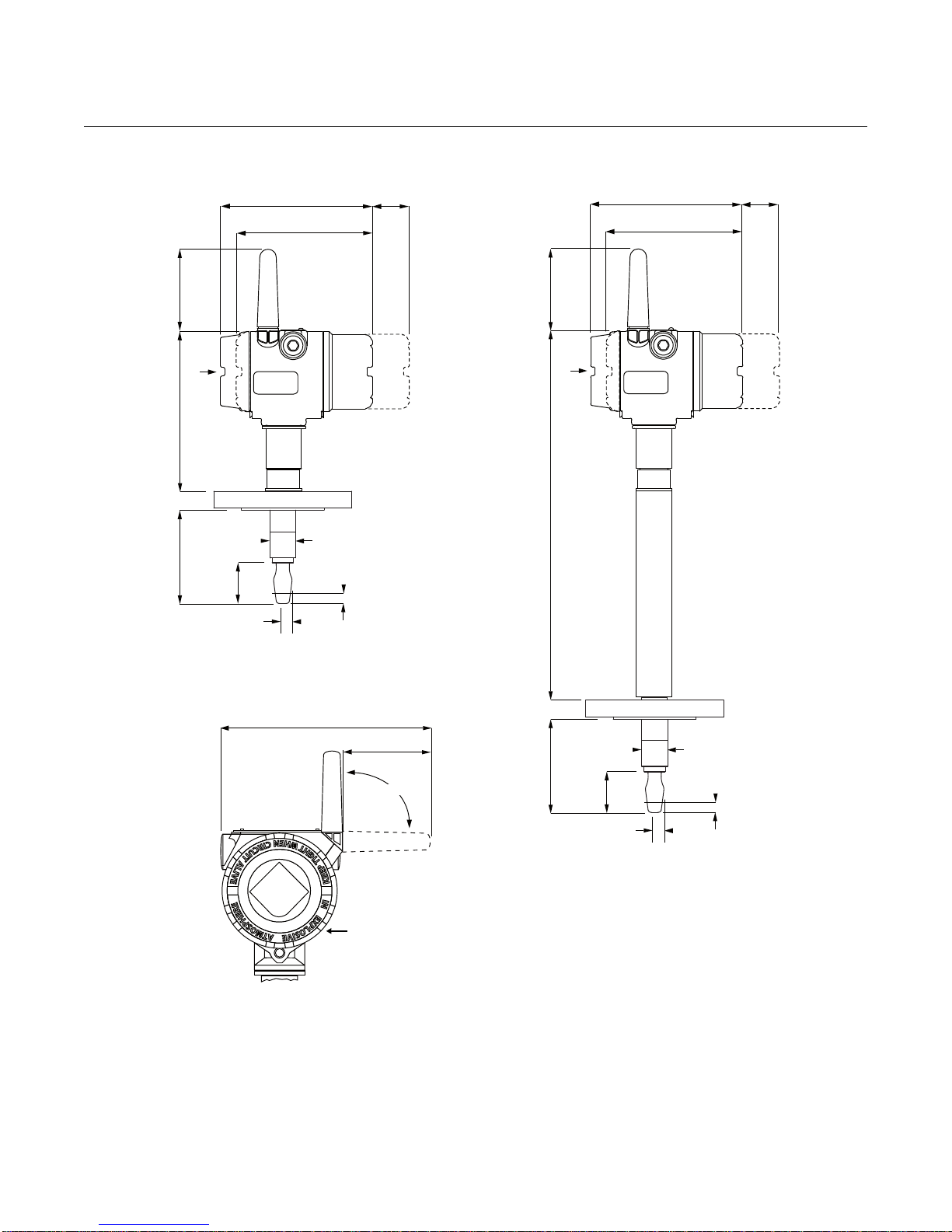
Rosemount 2160
A
A
1.7
(44)
4.0
(102)
0.5 (13) Switchpoint
(When Mounted Horizontally)
1.14 (29) for 1
1
/2 in. or
Larger Flange;
0.9 (23) for up to 1 in. Flange
0.5 (13) Switchpoint
(When Mounted Vertically)
90°
13.8
(351)
1.7
(44)
4.0
(102)
0.5 (13) Switchpoint
(When Mounted Horizontally)
1.14 (29) for 1
1
/2 in. or
Larger Flange;
0.9 (23) for up to 1 in. Flange
0.5 (13) Switchpoint
(When Mounted V ertically )
2160***S
2160***E
7.0
(177)
3.5
(90)
3.5
(90)
6.1 (154) No LCD Fitted
Minimum
To Allow
Removal
Of Cover
6.8 (172) LCD Fitted
2.4
(60)
6.8 (172) LCD Fitted
6.1 (154) No LCD Fitted
Minimum
To Allow
Removal
Of Cover
2.4
(60)
Aluminum
Housing
View On
Arrow ‘A’
Showing
Possible
Antenna
Rotation
7.9 (200)
3.7 (93)
Reference Manual
00809-0100-4160, Rev AB
March 2010
2160 Flange Mounting (Standard Length)
Note: Dimensions are in inches (millimeters)
A-8
Page 85
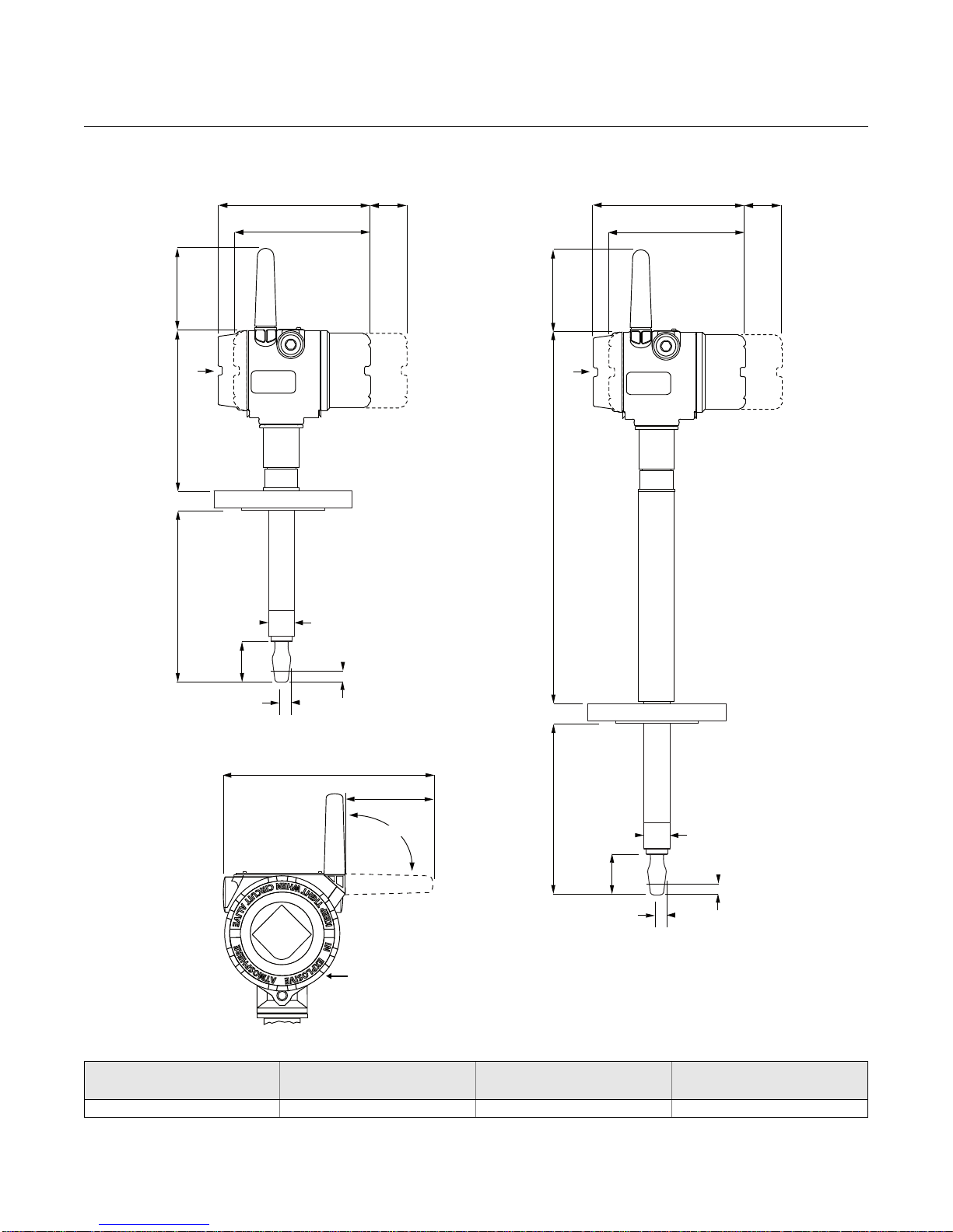
Reference Manual
A
A
1.7
(44)
E(M)
0.5 (13) Switchpoint
(When Mounted Horizontally)
1.14 (29) for 1
1
/2 in. or
Larger Flange;
0.9 (23) for up to 1 in. Flange
0.5 (13) Switchpoint
(When Mounted Vertically)
7.0
(177)
13.8
(351)
1.7
(44)
0.5 (13) Switchpoint
(Mounted Horizontally)
1.14 (29) for 1
1
/2 in. or
Larger Flange;
0.9 (23) for up to 1 in. Flange
0.5 (13) Switchpoint
(When Mounted Vertically)
E(M)
2160***S
2160***E
3.5
(90)
3.5
(90)
6.1 (154) No LCD Fitted
Minimum
To Allow
Removal
Of Cover
6.8 (172) LCD Fitted
2.4
(60)
6.8 (172) LCD Fitted
6.1 (154) No LCD Fitted
Minimum
To Allow
Removal
Of Cover
2.4
(60)
90°
Aluminum
Housing
View On
Arrow ‘A’
Showing
Possible
Antenna
Rotation
7.9 (200)
3.7 (93)
00809-0100-4160, Rev AB
March 2010
Rosemount 2160
2160 Flange Mounting (Extended Length)
Note: Dimensions are in inches (millimeters)
Table A-5. Flange Mounting Fork Length
3
/4 in, 1 in. or larger flange 4.0 in. (102 mm) 3.5 in. (89 mm) 118.1 in. (3000 mm)
Process
Connection
Standard Length
Fork Length Code H
Minimum Length
Fork Length Code E(M)
Maximum Length
Fork Length Code E(M)
A-9
Page 86
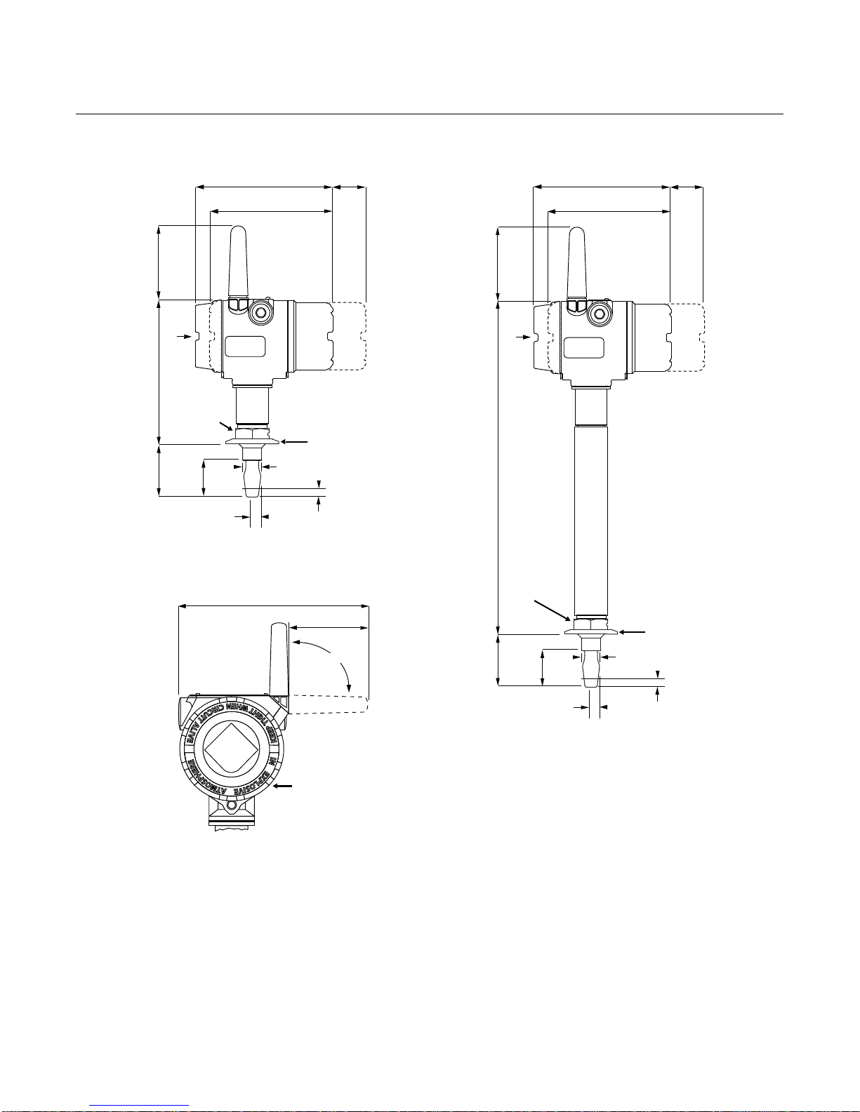
Rosemount 2160
A
A
1.14
(29)
1.7
(44)
2.5
(64)
1
/2 in. (38) or
2 in. (51) Tri-Clamp
1.6 (40) A/F
Hexagon
1.14
(29)
1.7
(44)
1.6 (40) A/F
Hexagon
0.5 (13) Switchpoint
(When Mounted Horizontally)
0.5 (13) Switchpoint
(When Mounted Vertically)
0.5 (13) Switchpoint
(When Mounted Vertically)
0.5 (13) Switchpoint
(When Mounted Horizontally)
2.5
(64)
7.1
(179)
14.9
(379)
1
/2 in. (38) or
2 in. (51) Tri-Clamp
2160***S
2160***E
3.5
(90)
3.5
(90)
6.1 (154) No LCD Fitted
Minimum
To Allow
Removal
Of Cover
6.8 (172) LCD Fitted
2.4
(60)
6.8 (172) LCD Fitted
6.1 (154) No LCD Fitted
Minimum
To Allow
Removal
Of Cover
2.4
(60)
90°
Aluminum
Housing
View On
Arrow ‘A’
Showing
Possible
Antenna
Rotation
7.9 (200)
3.7 (93)
Reference Manual
00809-0100-4160, Rev AB
March 2010
2160 Hygienic Fitting (Standard Length)
Note: Dimensions are in inches (millimeters)
A-10
Page 87
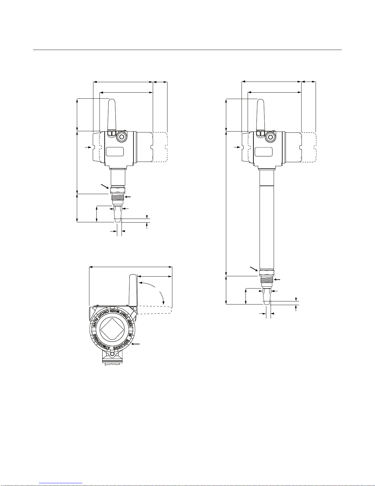
Reference Manual
1.14
(29)
1.7
(44)
3.1
(78)
1 in. Thread
1.14
(29)
1.7
(44)
1.6 (40 A/F
Hexagon
0.5 (13) Switchpoint
(When Mounted Horizontally)
0.5 (13) Switchpoint
(When Mounted Vertically)
0.5 (13) Switchpoint
(Mounted Vertically)
0.5 (13) Switchpoint
(When Mounted Horizontally)
3.1
(78)
7.0
(178)
14.6
(372)
1 in. Thread
2160***S
2160***E
3.5
(90)
3.5
(90)
6.1 (154) No LCD Fitted
Minimum
To Allow
Removal
Of Cover
6.8 (172) LCD Fitted
2.4
(60)
6.8 (172) LCD Fitted
6.1 (154) No LCD Fitted
Minimum
To Allow
Removal
Of Cover
2.4
(60)
90°
Aluminum
Housing
View On
Arrow ‘A’
Showing
Possible
Antenna
Rotation
7.9 (200)
3.7 (93)
1.6 (40 A/F
Hexagon
00809-0100-4160, Rev AB
March 2010
Rosemount 2160
2160 Hygienic Fitting (Standard Length) Continued
A
Note: Dimensions are in inches (millimeters)
A
A-11
Page 88
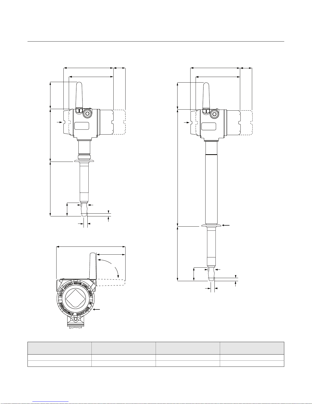
Rosemount 2160
A
A
1.14
(29)
1.7
(44)
1
/2 in. (38) or
2 in. (51) Tri-Clamp
E(M)
0.5 (13) Switchpoint
(When Mounted Vertically)
0.5 (13) Switchpoint
(When Mounted Horizontally)
14.9
(379)
7.1
(179)
E(M)
0.5 (13) Switchpoint
(When Mounted Vertically)
1.7
(44)
1.14
(29)
2160***S
2160***E
0.5 (13) Switchpoint
(Mounted Horizontally)
3.5
(90)
3.5
(90)
90°
Aluminum
Housing
View On
Arrow ‘A’
Showing
Possible
Antenna
Rotation
7.9 (200)
3.7 (93)
6.1 (154) No LCD Fitted
Minimum
To Allow
Removal
Of Cover
6.8 (172) LCD Fitted
2.4
(60)
6.8 (172) LCD Fitted
6.1 (154) No LCD Fitted
Minimum
To Allow
Removal
Of Cover
2.4
(60)
Reference Manual
00809-0100-4160, Rev AB
March 2010
2160 Hygienic Fitting (Extended Length)
Note: Dimensions are in inches (millimeters)
Table A-6. Hygienic Fitting Fork Length
(1) Maximum extended length of fork with hand-polished option is 39.4 in. (1000 mm).
Process
Connection
Tri-Clamp
1 in. Threaded 1.73 in. (44 mm) (No Extended Length Version) (No Extended Length Version)
Standard Length
Fork Length Code H
1.73 in. (44 mm) 4.13 in. (105 mm) 118.1 in. (3000 mm)
Minimum Length
Fork Length Code E(M)
Fork Length Code E(M)
Maximum Length
(1)
A-12
Page 89
Reference Manual
00809-0100-4160, Rev AB
March 2010
Rosemount 2160
ORDERING INFORMATION
Table A-7. 2160 Ordering Information
★The Standard offering represents the most common models and options. These options should be selected for best delivery.
The Expanded offering is subject to additional delivery lead time.
Model Product Description / Process Temperature
2160 WirelessHART™ Vibrating Fork Liquid Level Switch
Output
Standard
X Wireless
Housing Material
Standard
D Dual Compartment Housing - Aluminum (Aluminium)
Conduit Entry / Cable Threads
Standard
8
Operating Temperature
Standard
S Standard: –40 °F (–40 °C)...302 °F (150 °C)
E Extreme: –94 °F (–70 °C)...500 °F (260 °C)
Material of Construction: Process Connection / Fork
Standard
(1)
S
Expanded
(2)
H
Process Connection Size
Standard
9
1 1 in. / 25 mm (DN25)
2 2 in. / 50 mm (DN50)
5 11/2 in. / 40 mm (DN40)
3 3 in. / 80 mm (DN80)
4 4 in. / 100 mm (DN100)
6 6 in. / 150 mm (DN150)
8 8 in. / 200 mm (DN200)
7 21/2-in. / 65 mm (DN65)
Expanded
(3)
X
Process Connection Rating
Standard
AA ASME B16.5 Class 150 flange
AB ASME B16.5 Class 300 flange
DB EN1092-1 PN25/40 flange
NN For use with non-flange process connection type
Expanded
AC ASME B16.5 Class 600 flange
DA EN1092-1 PN10/16 flange
DC EN1092-1 PN63 flange
DD EN1092-1 PN100 flange
(3)
XX
Process Connection Type
Standard
R Raised Face (RF) flange
B BSPT (R) thread
G BSPP (G) thread
N NPT thread
1
/2-in. NPT thread
316/316L Stainless Steel (1.4401/1.4404) dual certified
Alloy C (UNS N10002), Alloy C-276 (UNS N10276), solid
3
/4 in.
Customer specific
Customer specific
Standard
★
Standard
★
Standard
★
Standard
★
★
Standard
★
Standard
★
★
★
★
★
★
★
★
★
Standard
★
★
★
★
Standard
★
★
★
★
A-13
Page 90
Reference Manual
00809-0100-4160, Rev AB
Rosemount 2160
Table A-7. 2160 Ordering Information
★The Standard offering represents the most common models and options. These options should be selected for best delivery.
The Expanded offering is subject to additional delivery lead time.
P BSPP (G) O-ring
C Tri-Clover Clamp
Expanded
(3)
X
Fork Length
Standard
A Standard length 1.7 in. (44 mm)
(4)
H
0000 Factory default length (only if fork length A or H is selected)
(5)
E
(5)
M
(5)
xxxx
Surface Finish (Wetted Parts)
Standard
1 Standard surface finish
2 Hand polished (Ra < 0.4 µm)
Approvals
Standard
NA No hazardous locations certifications
I1 ATEX Intrinsic Safety
I5 FM Intrinsic Safety and Non-Incendive
(6)
I6
I7 IECEx Intrinsic Safety
Wireless Update Rate, Operating Frequency and Protocol
Standard
WA3 User configurable update rate, 2.4 GHz DSSS, WirelessHART
Omnidirectional Wireless Antenna and SmartPower
Standard Note: The long-life Power Module must be shipped separately. Order Part #00753-9220-0001.
WK1 Long range, integral antenna, long-life power module adapter, intrinsically safe
Meter
Standard
M5 LCD meter
Factory Configuration Option
Standard
C1 Factory configure Date, Descriptor, Message Fields and Wireless Parameters
Calibration Data Certification
Standard
Q4 Certificate of functional test
Material Traceability Certification Option
Standard
Q8 Material traceability certification per EN 10204 3.1B
Special Procedures Option
Standard
P1 Hydrostatic testing with certificate. Option limited to units of no more then 59.1-in. (1500 mm) extended lengths.
Typical Model Number: 2160 X D 8 S S 1 NN N A0000 1 I5 WA3 WK1 M5 Q8
(1) Flanges are dual certified 316 and 316L Stainless Steel (1.4401 and 1.4404).
(2) Only available of BSPT and NPT threaded process connection types as standard, other upon request.
(3) Other process connections available upon request.
(4) Not available for hand polished wet side.
(5) Example: Code E1181 is 1 18.1 inches. Code M3000 is 3000 millimet ers. See Extended Lengths on p ageA-2 for minimum and maximum extended leng ths.
(6) The requirements of CRN are met when a Rosemount 2160 CSA-approved vibrating fork level switch model 2160****S**********I6****** is configured with
Customer specific
Standard length flange 4.0 in. (102 mm)
Extended, customer specified length in tenths of Inches
Extended, customer specified length in millimeters
Specific customer specified length in tenths of inches, or millimeters (only if fork length E or M is selected)
CSA Intrinsic Safety
316/316L stainless steel (1.4401/1.4404) wetted parts and either NPT threaded or 2-in. to 8-in. ASME B16.5 flanged process connections.
March 2010
Standard
Standard
Standard
Standard
Standard
Standard
Standard
Standard
Standard
Standard
★
★
★
★
★
★
★
★
★
★
★
★
★
★
★
★
★
★
★
★
A-14
Page 91

Reference Manual
00809-0100-4160, Rev AB
March 2010
Rosemount 2160
Spare Parts and
Accessories
Table A-8. Spare Parts and Accessories
★The Standard offering represents the most common models and options. These options should be selected for best delivery.
The Expanded offering is subject to additional delivery lead time.
Spares and Accessories
Standard Standard
02100-1000-0001 Seal for 1-in. BSPP (G1A). Material: Non-asbestos BS7531 grade X carbon fiber with rubber binder
02100-1040-0001 Seal for 3/4-in. BSPP (G3/4A). Material: Non-asbestos BS7531 grade X carbon fiber with rubber binder
02100-1010-0001 Hygienic adaptor boss 1-in. BSPP. Material: 316 SS fitting. FPM/FKM ‘O’ ring
02100-1020-0001 2-in. (51 mm) Tri-clamp kit (vessel fitting, clamp ring, and seal). Material: 316 St. steel, NBR Nitrile
02120-2000-0001
02120-2000-0002
(1) The adjustable clamp gland is not explosion-proof.
(1)
Adjustable clamp gland for 1-in. extended lengths. Material: 316 St. steel, (Si) Silicone rubber seal
(1)
Adjustable clamp gland for 1-in. extended lengths. Material: 316 St. steel, (Si) Silicone rubber seal
★
★
★
★
★
★
A-15
Page 92

Rosemount 2160
Reference Manual
00809-0100-4160, Rev AB
March 2010
A-16
Page 93

Reference Manual
00809-0100-4160, Rev AB
March 2010
Rosemount 2160
Appendix B Product Certifications
Approved Manufacturing Locations . . . . . . . . . . . . . . . . .page B-1
European Directive Information . . . . . . . . . . . . . . . . . . . .page B-1
Telecommunication Compliance . . . . . . . . . . . . . . . . . . . . page B-2
FCC and IC Approvals . . . . . . . . . . . . . . . . . . . . . . . . . . . . page B-2
Canadian Registration Number . . . . . . . . . . . . . . . . . . . . . page B-2
Hazardous Locations Certifications . . . . . . . . . . . . . . . . .page B-2
ROSEMOUNT 2160
Approved Manufacturing
Locations
European Directive
Information
Rosemount Inc.
— Chanhassen, Minnesota, USA
Mobrey Limited
— Slough, United Kingdom
Emerson Process Management Asia Pacific Private Limited
— Singapore
The EC declaration of conformity for all applicable European directives fo r this
product can be found at www.rosemount.com. A hard copy may be obtained
by contacting an Emerson Process Management representative.
ATEX Directive (94/9/EC)
Emerson Process Management complies with the ATEX Directive
European Pressure Equipment Directiv e (PED ) (9 7/ 23 /EC)
The 2160 is outside the scope of PED Directive
L.V. Directive
EN61010-1 Pollution degree 2, Category II (264V max), Pollution degree 2,
Category III (150V max)
Electro Magnetic Compatibility (EMC) (2004/108/EC)
www.rosemount.com
EN 61326-1:2006
Radio and Telecommunications Terminal Equipment Directive
(R&TTE)(1999/5/EC)
Emerson Process Management complies with the R&TTE Directive
Page 94

Rosemount 2160
Reference Manual
00809-0100-4160, Rev AB
March 2010
Telecommunication
Compliance
All wireless devices require certification to ensure that they adhere to
regulations regarding the use of the RF spectrum. Nearly every country
requires this type of product certification. Emerson is working with
governmental agencies around the world to supp ly fully compliant products
and remove the risk of violating country directives or laws governing wireless
device usage. To see which countries our devices have received certification
for use in, see www.rosemount.com/smartwireless.
FCC and IC Approvals This device complies with part 15 of the FCC Rules. Operation is subject to
the following two conditions: (1) This device may not cause harmful
interference, and (2) this device must accept any interference received,
including interference that may cause undesired operation.
FCC ID: LW2RM2510
IC ID: 2731A-RM2510
Canadian Registration
CRN 0F04227.2
Number
NOTE:
Rosemount 2160 CSA-approved vibrating fork level switch model
2160****S**********I6****** when configured with 316/316L stainless steel
(1.4401/1.4404) wetted parts and e ither NPT threaded process or 2 in. to 8 in.
ASME B16.5 flanged process connections meets the requirements of CRN.
Hazardous Locations
American and Canadian Approvals
Certifications
Factory Mutual (FM) Approvals
I5 Project ID: 3036541
FM Intrinsic Safety, Non-incendive, and Dust Ignition-proof
Intrinsically Safe for Class I, Division 1, Groups A, B, C, and D.
Zone Marking: Class I, Zone 0, AEx ia llC
Temperature Codes T4 (T
Non-incendive for Class I, Division 2, Groups A, B, C, and D.
Dust Ignition-proof for Class II/III, Division I, Groups E, F, and G.
Ambient temperature limits: –50 to 70 °C
Intrinsically Safe and Non-incendive when installed in accordance with
Rosemount drawing 71097/1273 (see Figure B-1 on page B-4).
For use with Rosemount SmartPower
P/N 753-9220-0001 only.
Enclosure Type 4X / IP66
= –50 to 70° C)
a
®
options
B-2
Page 95

Reference Manual
00809-0100-4160, Rev AB
March 2010
Rosemount 2160
Canadian Standards Association (CSA) Approvals
I6 Certificate Number: 06 CSA 1786345
CSA Intrinsic Safety
Intrinsically Safe for Class I, Division 1, Groups A, B, C, and D.
Temperature Code T3C
Enclosure Type 4X / IP66
For use with Rosemount SmartPower options
P/N 753-9220-0001 only.
Intrinsically Safe when installed in accordance with Rosemount drawing
71097/1271 (see Figure B-2 on page B-5).
European Certifications
ATEX Approvals
I1 ATEX Intrinsic Safety
Certificate Number: Baseefa 09ATEX0253X
II 1 G, Ex ia IIC T4-T2 (T
IP66
For use with Rosemount SmartPower options
P/N 753-9220-0001 only.
Special conditions for safe use:
The surface resistivity of the antenna is greater than
1 gigaohm. To avoid electrostatic charge build-up, it must not be rubbed
or cleaned with solvents or a dry cloth.
= –40 to 70 °C)
a
Rest Of The World Certifications
IECEx Approvals
I7 IECEx Intrinsic Safety
Certificate Number: IECEx BAS 09.0123X
Ex ia IIC T4-T2 (T
IP66
For use with Rosemount SmartPower options
P/N 753-9220-0001 only.
Special conditions for safe use:
The surface resistivity of the antenna is greater than
1 gigaohm. To avoid electrostatic charge build-up, it must not be rubbed
or cleaned with solvents or a dry cloth.
= –40 to 70 °C)
a
B-3
Page 96
Rosemount 2160
A
WEEK
3
ISSUE
MODIF. ORDER NO.
WEEK
MODIF. ORDER NO.
ISSUE
WEEK
MODIF. ORDER NO.
ISSUE
2
B
C
SHEET
ISSUE
A3.DWG, 061024
MATERIAL
TITLE
FILE
DWG NO.
SCALE
PRODUCT CODE
DOC. TYPE
1 ST ANGLE
OTHERWISE STATED:
FINISH, UNLESS
3
ISSUED BY
APPROVED BY2TOLERANCES, UNLESS OTHERWISE STATED:
FOR CASTING: ISO 8062
FOR MACHINING: ISO 2768
ALL DIMENSIONS ARE IN MILLIMETRES.
WEEK
WEEK
FOR WELDING: SS-EN ISO 13920
WILL BE PROSECUTED. ROSEMOUNT TANK RADAR AB, SWEDEN.
OR BROUGHT TO THE KNOWLEDGE OF A THIRD PARTY. CONTRAVENTION
THE COPYRIGHT/OWNERSHIP OF THIS DOCUMENT IS AND WILL REMAIN
OURS. THE DOCUMENT MUST NOT BE USED WITHOUT OUR AUTHORIZATION
1
A
ORIGINALFORMAT A3
B
1
C
mK
CT10
A, E
6.3
ONLY THE FM APPROVED
375 FIELD COMMUNICATOR
MAY BE CONNECTED TO
THE HART TERMINALS.
2160X**E*
2160X**S*
ALTERATIONS TO THIS DOCUMENT MUST BE
APPROVED BEFORE IMPLEMENTATION.
CERTIFIED PRODUCT
MINIMUM AMBIENT AIR TEMPERATURE (Ta) = -50
C
MINIMUM PROCESS TEMPERATURE (Tp) = -70
C
MINIMUM AMBIENT AIR TEMPERATURE (Ta) = -50
C
MINIMUM PROCESS TEMPERATURE (Tp) = -40
C
HAZARDOUS AREA
NOTES:
INSTALLATION OF EQUIPMENT TO BE IN ACCORDANCE WITH NEC ARTICLES 504 AND 505, AND
1.
ISA RP12.6 RECOMMENDED PRACTICE FOR INSTALLATION OF INTRINSICALLY SAFE CIRCUITS.
SUBSTITUTION OF COMPONENTS MAY IMPAIR INTRINSIC SAFETY OR SUITABILITY FOR
2.
DIVISION 2.
WARNING: THE SURFACE RESISTIVITY OF THE ANTENNA IS GREATER THAN 1GOhm. TO AVOID
3.
ELECTROSTATIC CHARGE BUILD-UP, IT MUST NOT BE RUBBED OR CLEANED WITH SOLVENTS
OR A DRY CLOTH.
WARNING: THE POWER MODULE MAY BE REPLACED IN A HAZARDOUS AREA. THE POWER
4.
MODULE HAS SURFACE RESISTIVITY GREATER THAN 1 GOhm AND MUST BE PROPERLY
INSTALLED IN THE WIRELESS DEVICE ENCLOSURE. CARE MUST BE TAKEN DURING
TRANSPORTATION TO AND FROM THE POINT OF INSTALLATION TO PREVENT ELECTROSTATIC
DISCHARGE BUILD-UP.
DUST-TIGHT CONDUIT SEAL MUST BE USED WHEN INSTALLED IS CLASS II AND CLASS III
5.
ENVIRONMENTS.
FOR FURTHER INFORMATION REFER TO MANUAL 00809-0100-4160.
6.
ROSEMOUNT 2160 TRANSMITTERS ARE FM APPROVED AS THE FOLLOWING:
INTRINSICALLY SAFE FOR USE IN CLASS I, DIVISION 1, GROUPS A,B,C,D
INTRINSICALLY SAFE FOR USE IN CLASS I, ZONE 0, AEx ia IIC
NONINCENDIVE CLASS I, DIVISION 2, GROUPS A,B,C,D
DUST-IGNITION PROOF CLASS II/III, DIVISION I,GROUPS E,F,G
Temperature Classes
Maximum Ambient Air
Temperature (Ta)
Maximum Process
Temperature (Tp)
T4, T3, T2, T1
70
C
100
C
T4, T3, T2, T1
60
C
115
C
T3, T2, T1
50
C
150
C
Temperature Classes
Maximum Ambient Air
Temperature (Ta)
Maximum Process
Temperature (Tp)
T4, T3, T2, T1
70
C
115
C
T3, T2, T1
65
C
185
C
T2, T1
60
C
260
C
X
XX
DJS
52
X
0
1:2
ACAD
FM INTRINSICALLY SAFE
CONTROL DRAWING, 2160
71097/1273
6 1/1
------
624
MOB-00577
520
MOB-00453
474
MOB-00062
Figure B-1.
FM Control Drawing
Reference Manual
00809-0100-4160, Rev AB
March 2010
B-4
Page 97
Reference Manual
A
WEEK
3
ISSUE
MODIF. ORDER NO.
WEEK
MODIF. ORDER NO.
ISSUE
WEEK
MODIF. ORDER NO.
ISSUE
2
B
C
SHEET
ISSUE
A3.DWG, 061024
MATERIAL
TITLE
FILE
DWG NO.
SCALE
PRODUCT CODE
DOC. TYPE
1 ST ANGLE
OTHERWISE STATED:
FINISH, UNLESS
3
ISSUED BY
APPROVED BY2TOLERANCES, UNLESS OTHERWISE STATED:
FOR CASTING: ISO 8062
FOR MACHINING: ISO 2768
ALL DIMENSIONS ARE IN MILLIMETRES.
WEEK
WEEK
FOR WELDING: SS-EN ISO 13920
WILL BE PROSECUTED. ROSEMOUNT TANK RADAR AB, SWEDEN.
OR BROUGHT TO THE KNOWLEDGE OF A THIRD PARTY. CONTRAVENTION
THE COPYRIGHT/OWNERSHIP OF THIS DOCUMENT IS AND WILL REMAIN
OURS. THE DOCUMENT MUST NOT BE USED WITHOUT OUR AUTHORIZATION
1
A
ORIGINALFORMAT A3
B
1
C
mK
CT10
A, E
6.3
ONLY THE CSA APPROVED
375 FIELD COMMUNICATOR
MAY BE CONNECTED TO
THE HART TERMINALS.
ROSEMOUNT 2160 TRANSMITTERS ARE CSA APPROVED AS THE FOLLOWING:
INTRINSICALLY SAFE FOR USE IN CLASS I, DIVISION 1, GROUPS A,B,C,D
HAZARDOUS LOCATIONS TEMPERATURE CODE T3C
2160X**S*
2160X**E*
HAZARDOUS AREA
CERTIFIED PRODUCT
ALTERATIONS TO THIS DOCUMENT MUST BE
APPROVED BEFORE IMPLEMENTATION.
MINIMUM AMBIENT AIR TEMPERATURE (Ta) = -50
C
MINIMUM PROCESS TEMPERATURE (Tp) = -40
C
MINIMUM AMBIENT AIR TEMPERATURE (Ta) = -50
C
MINIMUM PROCESS TEMPERATURE (Tp) = -70
C
NOTES:
INSTALLATION OF EQUIPMENT INCLUDING ANY GROUNDING ARRANGEMENT TO BE IN
1.
ACCORDANCE WITH CANADIAN ELECTRICAL CODE RECOMMENDED PRACTICE FOR
INSTALLATION OF INTRINSICALLY SAFE CIRCUITS, OR THE INTRINSICALLY SAFE EQUIPMENT
INSTALLATION PRACTICE IN THE COUNTRY OF USE.
SUBSTITUTION OF COMPONENTS MAY IMPAIR INTRINSIC SAFETY.
2.
AVERTISSEMENT: LA SUBSTITUTION DE COMPOSANTS PEUT COMPROMETTRE LA
SECURITE INTRINSIQUE.
WARNING: THE SURFACE RESISTIVITY OF THE ANTENNA IS GREATER THAN 1GOhm. TO AVOID
3.
ELECTROSTATIC CHARGE BUILD-UP, IT MUST NOT BE RUBBED OR CLEANED WITH SOLVENTS
OR A DRY CLOTH.
WARNING: THE POWER MODULE MAY BE REPLACED IN A HAZARDOUS AREA. THE POWER
4.
MODULE HAS SURFACE RESISTIVITY GREATER THAN 1 GOhm AND MUST BE PROPERLY
INSTALLED IN THE WIRELESS DEVICE ENCLOSURE. CARE MUST BE TAKEN DURING
TRANSPORTATION TO AND FROM THE POINT OF INSTALLATION TO PREVENT ELECTROSTATIC
DISCHARGE BUILD-UP.
FOR FURTHER INFORMATION REFER TO MANUAL 00809-0100-4160.
5.
Temperature Classes
Maximum Ambient Air
Temperature (Ta)
Maximum Process
Temperature (Tp)
T3C, T2, T1
70
C
100
C
T3C, T2, T1
60
C
115
C
T3, T2, T1
50
C
150
C
Temperature Classes
Maximum Ambient Air
Temperature (Ta)
Maximum Process
Temperature (Tp)
T3C, T2, T1
70
C
115
C
T3, T2, T1
65
C
185
C
T2, T1
60
C
260
C
X
XX
DJS
52
X
0
1:2
ACAD
CSA INTRINSICALLY SAFE
CONTROL DRAWING, 2160
71097/1271
4 1/1
------
447
MOB-00062
30
ST7345
2333
ST7435
00809-0100-4160, Rev AB
March 2010
Figure B-2.
CSA Control Drawing
Rosemount 2160
B-5
Page 98

Rosemount 2160
Reference Manual
00809-0100-4160, Rev AB
March 2010
B-6
Page 99

Page 100

Rosemount 2160
Reference Manual
00809-0100-4160, Rev AB
March 2010
Standard Terms and Conditions of Sale can be found at www.rosemount.com\terms_of_sale
The Emerson logo is a trade mark and service mark of Emerson Electric Co.
Rosemount and the Rosemount logotype are registered trademarks of Rosemount Inc.
PlantWeb is a mark of one of the Emerson Process Management companies.
HART and WirelessHART are registered trademarks of the HART Communications Foundation.
All other marks are the property of their respective owners.
© 2009 Rosemount, Inc.
Emerson Process Management
Rosemount Inc.
8200 Market Boulevard
Chanhassen, MN 55317 USA
T (U.S.) 1-800-999-9307
T (International) (952) 906-8888
F (952) 949-7001
www.rosemount.com
00809-0100-4160 Rev AB 03/10
Emerson Process Management
Bleigistrasse 23
P.O. Box 1046
CH 6341 Baar
Switzerland
T +41 (0) 41 768 6111
F +41 (0) 41 768 6300
Emerson FZE
P.O. Box 17033
Jebel Ali Free Zone
Dubai UAE
T +971 4 883 5235
F +971 4 883 5312
Emerson Process Management
Asia Pacific Pte Ltd
1 Pandan Crescent
Singapore 128461
T +65 6777 8211
F +65 6777 0947
Service Support Hotline: +65 6770 8711
Email: [email protected]
 Loading...