

Page 1
NetPage Network Wireless Paging System (POCSAG)
NP-14 Series
Operation Manual
CCW152241-002
1
Page 2

INTRODUCTION
The NP-14 Network wireless paging system is a fully-programmable, single-board,
POCSAG encoder with Hi power synthesized transmitter for the on-site paging
system applications.
The unit provides a combined alarm input and link command paging solution via the
external computer, console, closing contacts or the RS232 port, RJ-45 Ethernet port,
provided. Which are suitable for the industrial alarm and commercial site paging,
where a fast response to a security problem monitoring is essential.
The typical applications includes the Fire, Security, Nurse call system, applications.
The communication to the transmitter via the RS232 port or RJ-45 port uses a
relatively simple protocol by SCOPE, TAP, Comp1, Comp2,…
The NP-14 is a single-board synthesized message transmitter that operates in the
410-490MHz, 868MHz, 915MHz, 931MHz, frequency bands.
The NP-14 transmitter encoder contents, which are the capcode, speed and
messages etc, can be sent by the tone-only, numeric(4-bit), alphanumeric(7-bit)
using the POCSAG paging protocol out from either the serial port or from the
Ethernet port.
The NP-14 option available also has 8 contacts for the alarm paging applications.
Each input is an independent port control. Whie the contact input status from the
open to short or from the short to open, the pre-programmed input capcode and
message will be sent out. All programming 8 inputs paging contents must be in the
same set frequency. Others such as the paging address, data rate, message,
repeater call time etc can be independent either all by same and all dirreferent.
■ The NP-14 Alarm contacts up to eight input control lines.
■ The NP-14 eight contacts input are all independent.
■ The NP-14 operates can by the RS-232 serial input.
■ The NP-14 operates can by the RJ-45 Ethernet input.
■ The NP-14 transmitter section is frequency synthesized unit.
■ The NP-14 system Communicate protocol by SCOPE, COMP2…
2
Page 3
Appearance
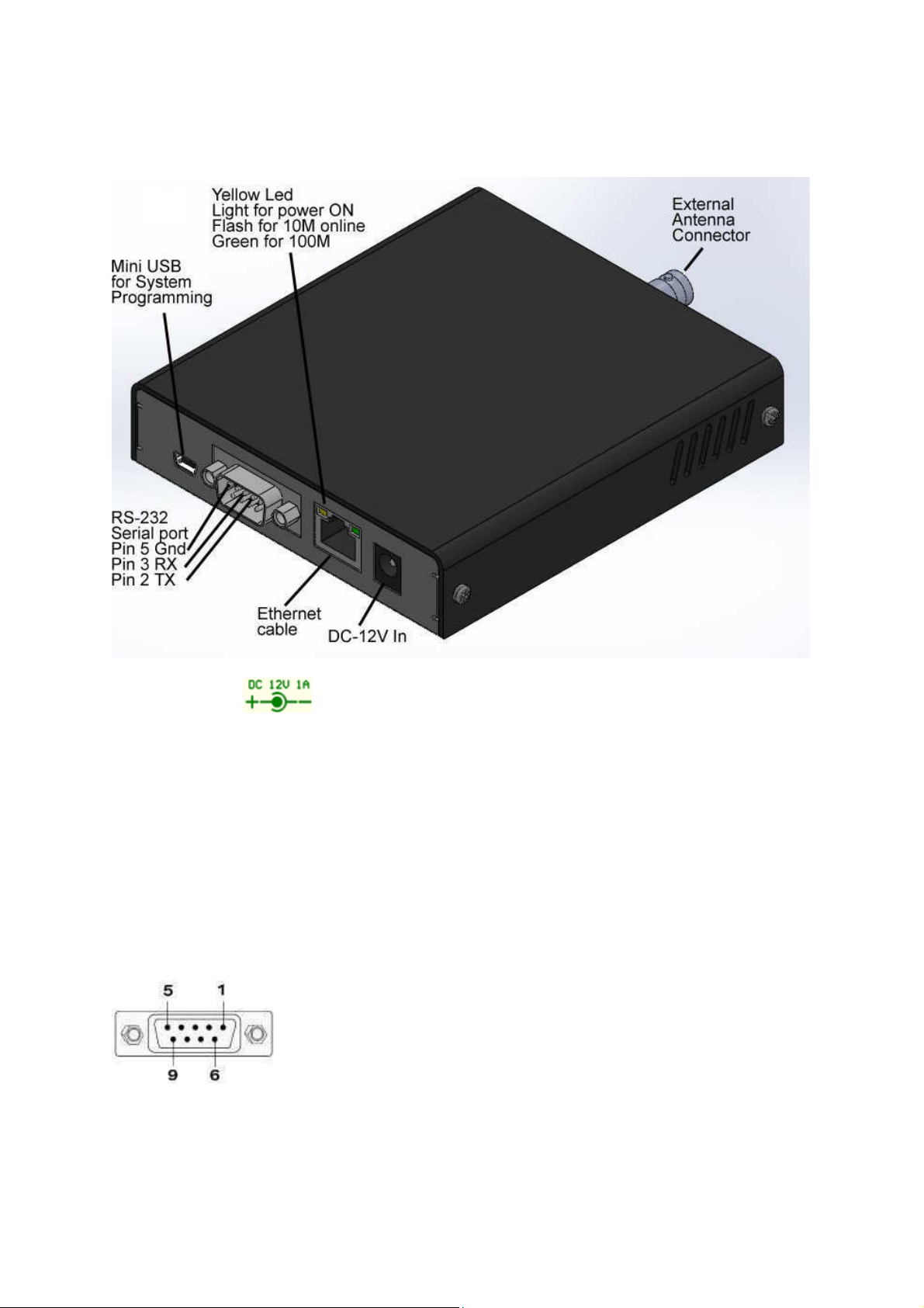
1. DC-12V IN : 10V-13.8V In Minimum 1A.
2. Ethernet cable: Connect to the Internet HUB by Cat.5 and up cable.
3. Ethernet LED indicate
Yellow on for power ON
Yellow flash for Net 10M link
Green flash for 100M link
4. RS-232 Serial port.
Pin 2
Pin 3
Pin 5
TX (data output To PC DB-9 Pin 2 RD)
RX (data received From PC DB-9 Pin 3 TD)
GND (required to PC DB-9 pin 5)
5. Mini USB for the System programming
6. RF output to antenna or RF amplifier.
3
Page 4
PROGRAMMABLE FEATURES
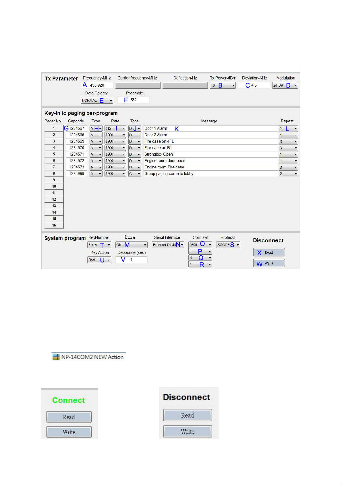
The photo screen below describes theNP-14 programmable features
↑Figure 2. Programming screen
Programmable and set up
While programming, the NP-14 DC plug must be off and disconnected, Just use
the DC power from PC USB.
Tips to set up the programming parameters
1. Install the programming AP execution file
2. Click PMX-NP and then runs the programming software.
3. Connect the USB plug into the your device and the PC USB port .
If show Disconnect Check USB Jack again.
4
Page 5
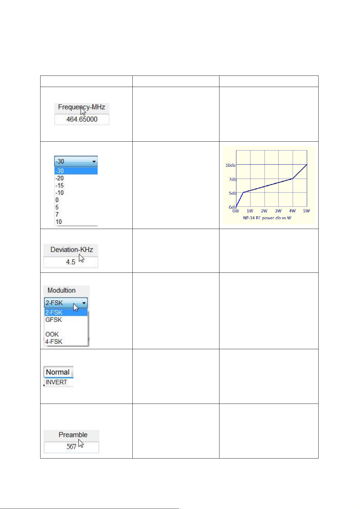
Example Programming Screen as Below:
Item Function Value
A- Carrier Frequency
Radio Frequency set-up
key-in your own frequency
410.000 to 490.995
850.000 to 890.995
910.0000 to 931.9375
B- TX RF Power
C- FSK Deviation
Transmitter RF Power set-up
The % Just for reference must
connect with RF power meter
for true output power
adjustment.
Frequency Deviation set-up Normal 4.0K or 4.5K (Max) for
POCSAG or 2 level data rate
D- Modulation type select
E- Data Polarity
F- POCSAG Preamble:
Frequency modulation set-up Normal 2-FSK (2 level FSK) for
POCSAG
Data Polarity Normal or Invert
set-up
Preamble for pager power
saving
Normal = 01010101--Invert = 10101010--General select Normal
Normal set 576 bits or more.
5
Page 6
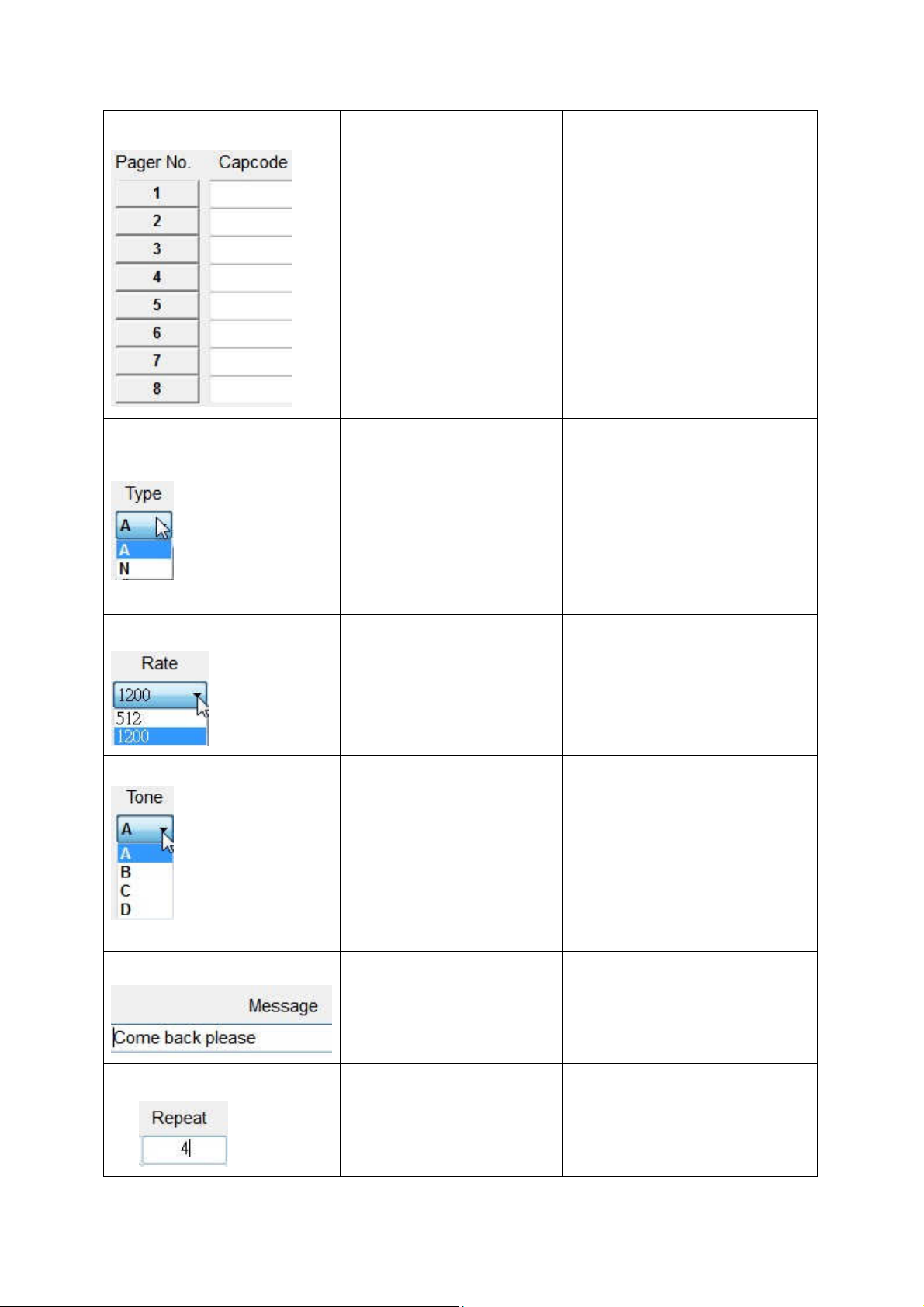
G- Page number of copcode
Pager copcode address
No 1-8 or 1-16 pager copcode can
H- Pager display type
selection
set-up
be all same or all difference
7digital POCSAG address range
from 0000008 to 2097151.
Numeric or Alphanumeric
Display Pager set-up
N for numeric display type, A for
alphanumeric display type.
I- Data Rate
J- Pager alert tone
K- Pre-program Message
Data speed set-up POCSAG data speed and baud
rate in 512bps or 1200bps
Must to be same as pager.
Pager alert tone select A=1beep per Sec,
B=2beeps per Sec,
C=3beeps per Sec,
D=4beeps per Sec.
Pre-programmed Message All ASCII words
L- Paging repeater
6
Repeater call times for each
paging
1=1 call
2=2 time call
3=3 time call
4=4 time call
Page 7
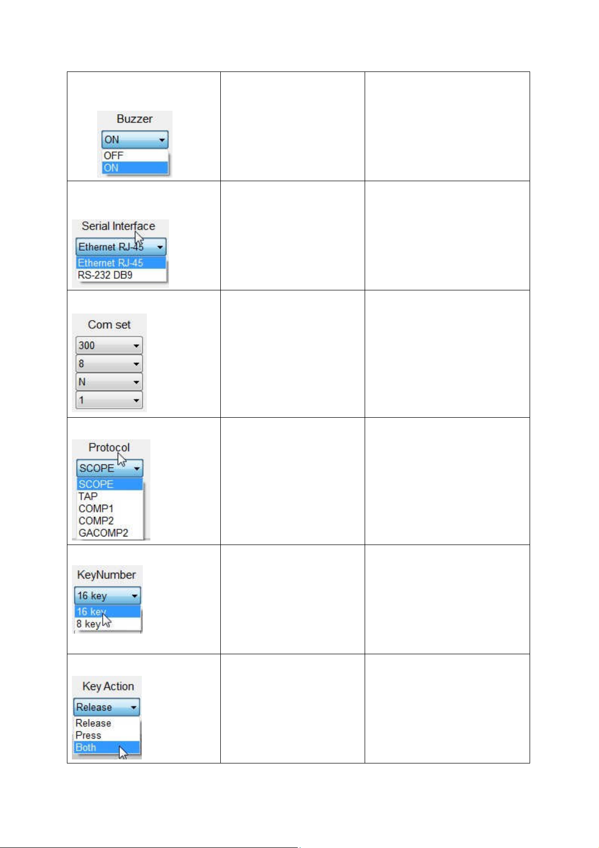
M- Buzzer On/off select
NP-14 TX Buzzer On or Off When NP-14 Transmitter
N- Link interface select
O- PC Communication set-up
Buzzer can be set beper sound
Command interface by
RS-232 serial or by RJ-45
Ethernet
O,P,Q,R-for Comport set up: General set 9600,8,N,1
RJ-45 = Internet
RS-232 = Serial port
S- Command protocol
T- Number of alarm input
U- Alarm Trig switch level
PC or Console command
protocol
Select alarm input number
8 input or 16 input
Select Alarm switch
from NC to NO for action
or NO to NC for action
SCOPE, TAP, Comp1, Comp2
GACOMP2….
Select 1 to meet your console
protocol
The NP-14 default is 8 alarm input
only
Release = Normal close to open
Press = Normal open to short
Both = Normal close to open and
or any (both)
7
Normal open to close for alarm
action
Page 8
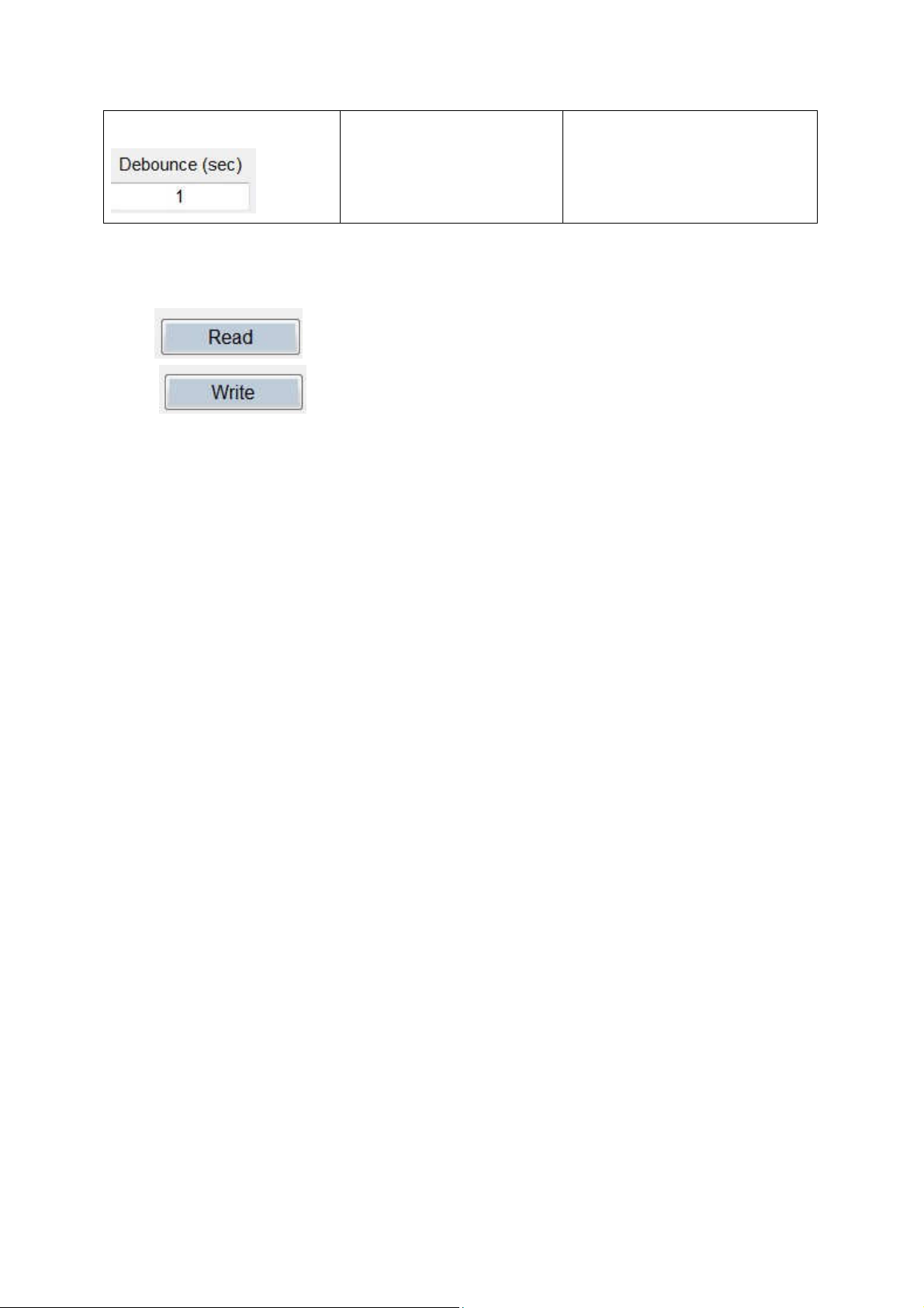
V- Alarm Trig over time
Duration action prohibited
If set 1 Sec, then over 1 Sec and
after the 1st activation
X- X-for Read : Reading the programmed contents from your devices.
W- W-for Write : Write the programming contents into your devices.
more time can be alarm action, if
under 1 Sec is Nothin.
8
Page 9
INSTALLATION
Introduction
This chapter provides basis information in installation help of the NP-14 Netpage
transmitter.
Installation
Installing the NP-14 involves identifying the interface connections for communication
with the host equipment and connecting the module. The connector pin orientation is
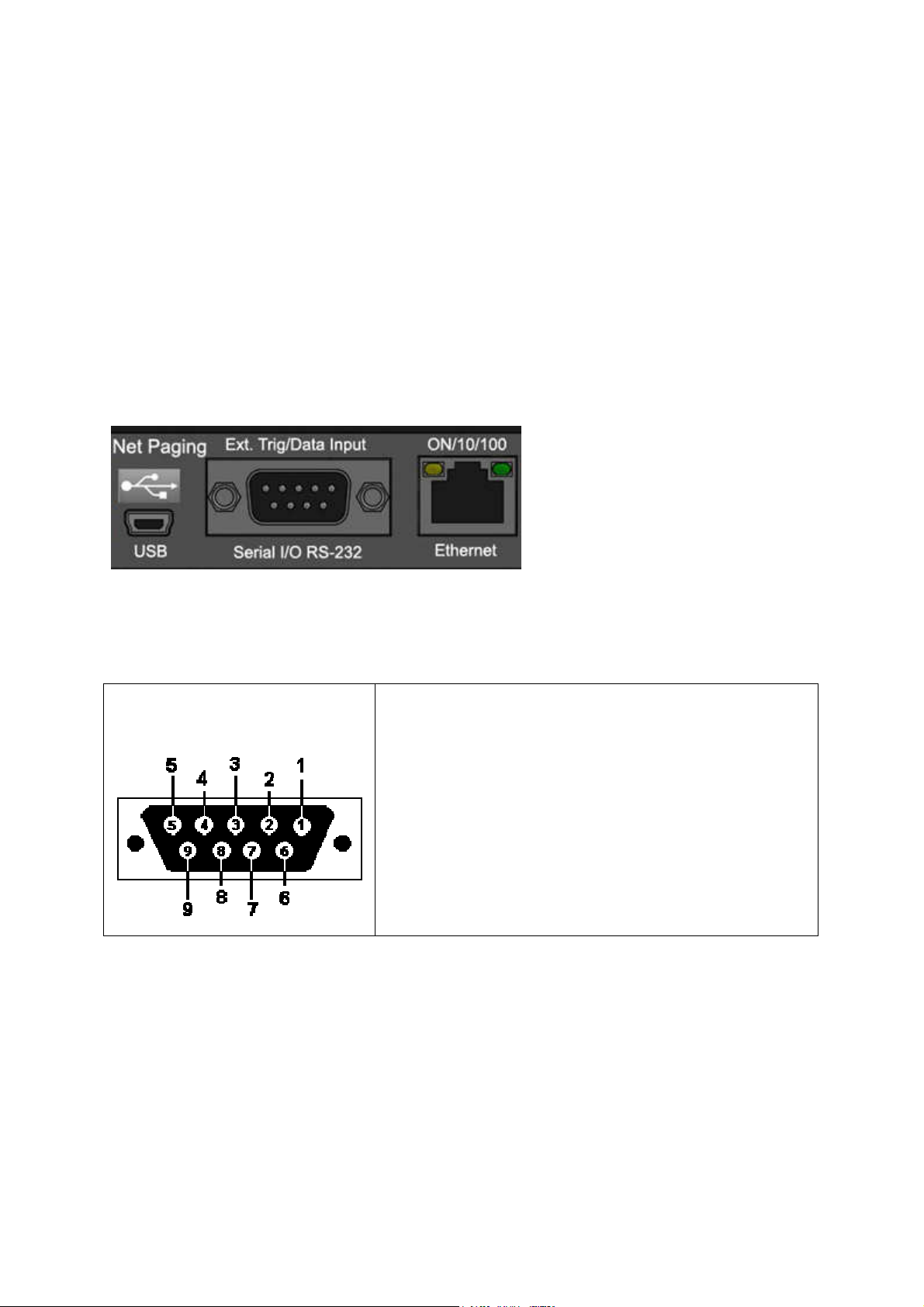
show in Figure 20 Corresponding signal name and color codes are listed in table
1-1.1-2.1-3.1-4.mount and connect the NP-14 as follows:
←←←←Figure 20. Main I/O of Rear view
Table 1-1.COM1,RS232 SERIAL PORTS (9 way female) PIN SIGNAL DIRECTION
DB9 - View looking into female
connector (NP-14 side)
1 N/C
2 RECEIVE DATA (RX) IN
3 TRANSMIT DATA (TX) OUT
4 N/C
5 GROUND (GND)
6 N/C
7 N/C
8 CLEAR TO SEND (CTS) IN
Link by RS-232
Plug the RS-232 Cable into an available DB9 serial port connector on the back of a Host Device, such
as a PC or Nurse Call system or other Host Device. If the serial port has a DB25 connector, you must
provide a DB25 to DB9 adapter, which is available from NP-14 or from a computer supply company.
Tighten the connector screws.
Plug the RS-232 Cable into the DB9 female connector on the Transmitter Unit. Tighten the connector
screws.
9
Page 10
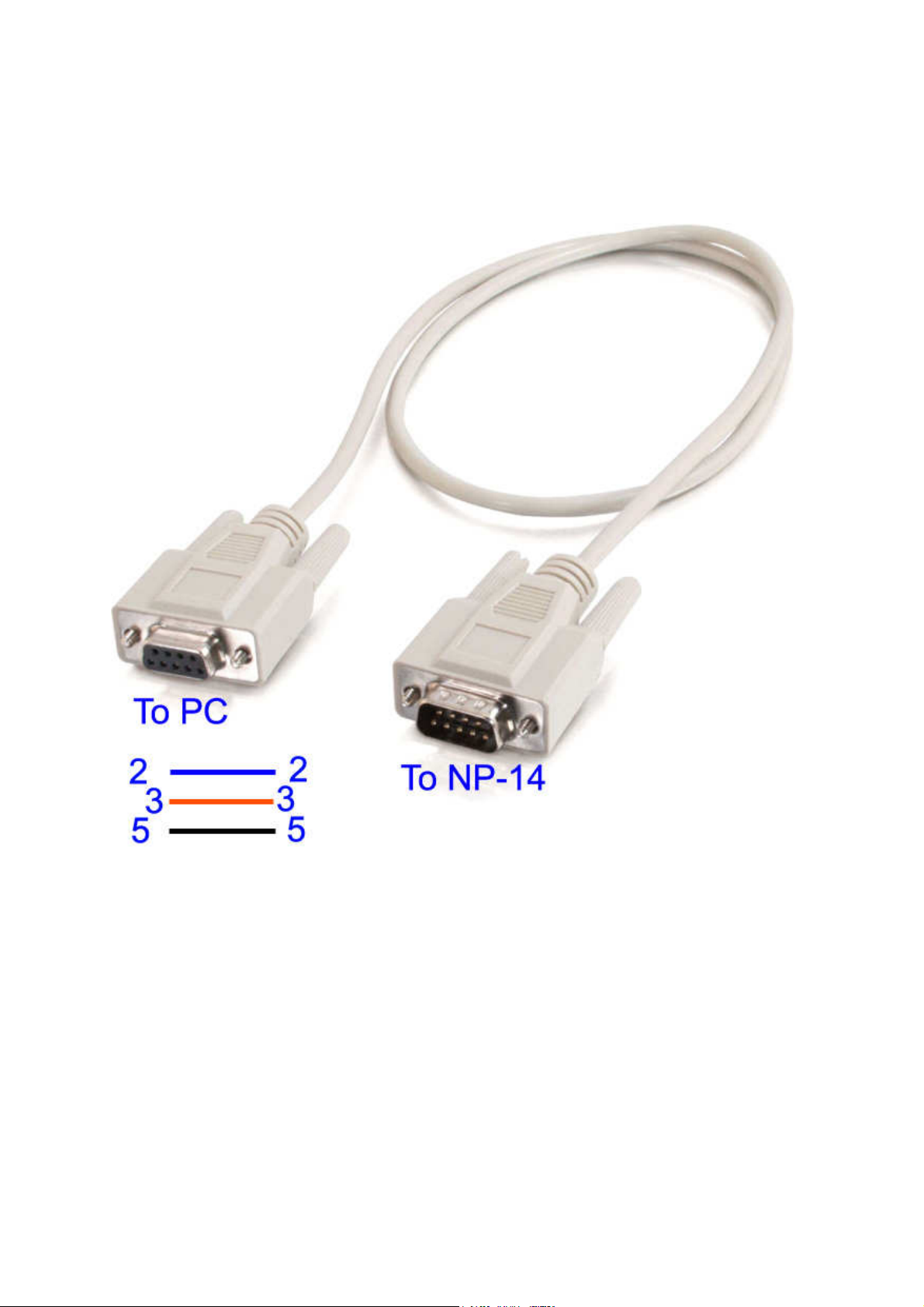
The RS-232 Cable is a parallel wire: Pin 2 to pin 2, Pin 3 to Pin 3. Pin 5 to pin 5.
Option serial RS-232 cable Part NO.86852933-00
10
Page 11
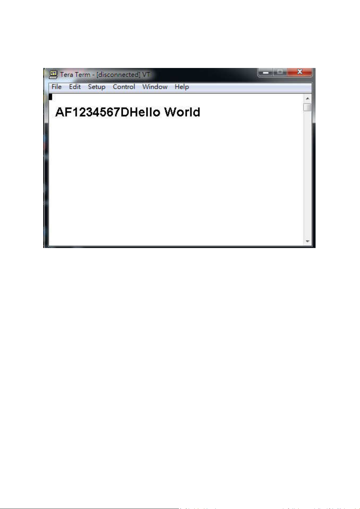
Command Protocol
For example by Hyperterminal
AF1234567DHello World……..
[A] Pager type Alphanumeric, N=Numeric
[F] Data bud rate, F=1200bps, N=512 bps, S=2400bps, if blank= Default 1200bps.
[1234567] Pager copcode, pager address.
[D] Pager tone alert, A for tone A, B for tone B, C for tone C, D for tone D.
[Hello World] message word.
Protocol Format Error Respond:
If the first character other than A or N --- Invalid Command format1!<CR><LF>
capcode fields appear with letter of alphabet --- Invalid Command
format2!<CR><LF>
capcode <8, >2097151 --- Capcode over range!<CR><LF>
message type field appears character out of the ABCD--- "Invalid Command
format3!\r\n"
message has the invisible character --- "Invalid Command format4!\r\n"
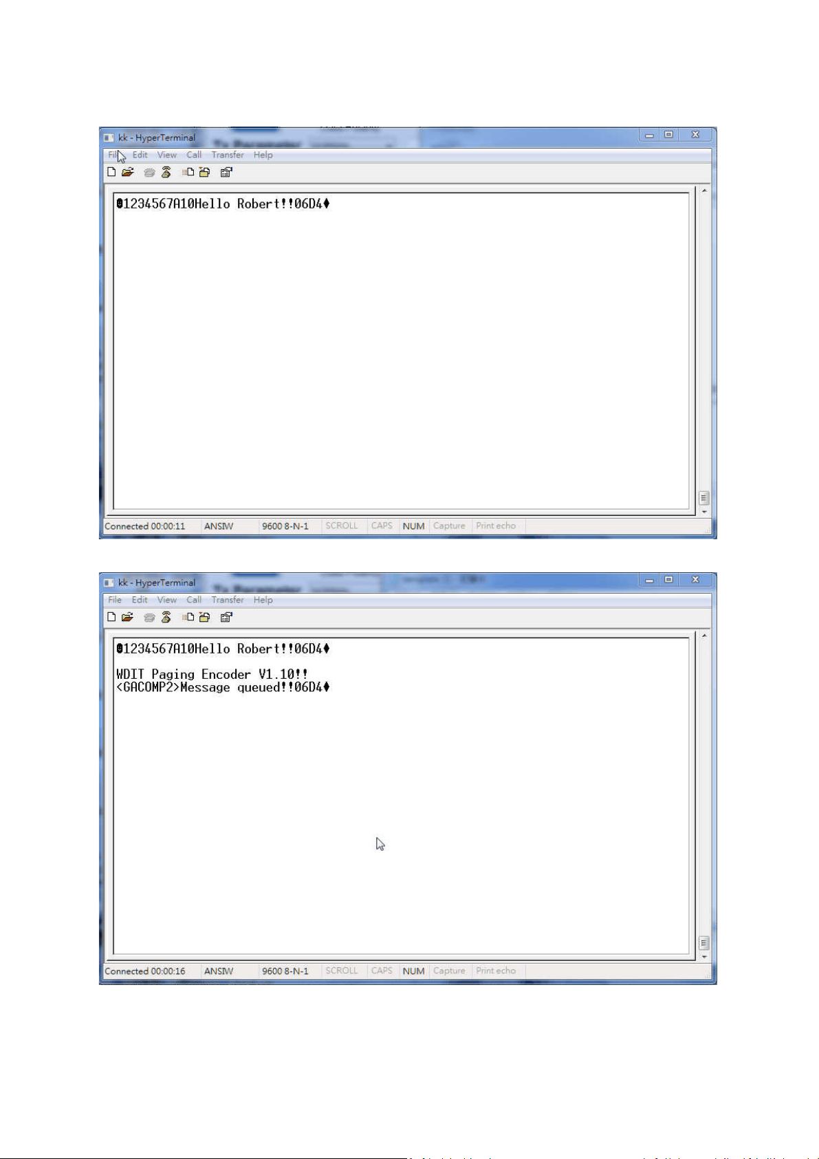
For example by Hyperterminal with GACOMP2 protocol
11
Page 12
12
Page 13

GACOMP2 protocol V1.32
This protocol is defined for a POCSAG encoder with RS-232 in baud rate
( 9600 ,N,8,1 ) of PC .
PC send to Transmitter
Transmitter command format ( All contents is visible ASCII code exclude the STX and
EOT) =
STX + Capcode content + Message content + CheckSum + EOT
= 02H + AAAAAAAERF + Message content + CCCC + 04H
Format Description :
Contents are all visible ASCII code value >= 20 Hex except the STX and EOT
command
STX is 02 Hex code , it is not visible in ASCII code
EOT is 04 Hex code , it is not visible in ASCII code
Capcode content = AAAAAAAERF
(a) AAAAAAA is a 7 digits numeric between 0000008 - 2097151 representing a
pager or RCM receiver capcode
(b) E is 0,n,or N represent numeric encoding, and 1,a,or A represent alphanumeric
encoding
(c) R is RF data rate, where 5 represents 512 bps, 1 represents 1200 bps, and 2
represents 2400 bps
(d) F is 0,1,2,3,or 4 defines the function code to be delivered.
It is 0 represent the default value for F is 4 when the E value is alphanumeric, and 1
when the E value is numeric
Numeric message = 0 to F Hex that transfer to visible ASCII code is 30H to 39H (0 –
9) and 41H to 45H (A – F).
Message content = any message you want send out ,if you did not carry any
message then it will send out a "Tone Only" message output
CheckSum(CCCC) is a 4 number of ASCII code include all contents before
CheckSum ( STX + Capcode content + Message content )
CheckSum example : Capcode content Message content CheckSum
EX 1. Num.1200bps 1000001N11 1234ABCD 03D8
Description :
CheckSum = 3D8H (02H+31H+30H+30H+30H+30H+30H+
31H+4EH+31H+31H+31H+32H+33H+34H+41H+42H+43H+44H)
CCCC = 03D8 (30H,33H,44H,38H)
Total contents = 02H + ”1000001N111234ABCD03D8” + 04H
EX 2. Alpha 1200bps 0000128
A11 abcdefghijk 0662
13
Page 14

Description :
CheckSum = 662H (02H+30H+30H+30H+30H+31H+32H+38H+41H+31H
+31H+61H+62H+63H+64H+65H+66H+67H+68H+69H+6AH+6BH)
CCCC = 0662 (30H,36H,36H,32H)
Total contents = 02H + “0000128A11abcdefghijk0662” + 04H
EX3. Num. 512 bps 1000122N51 xxx… 6A3C
Description : CheckSum = 126A3CH ( only use last 4 digits as valid ) CCCC = 6A3C
(36H,41H,33H,43H)
Transmitter send to PC
If command accept to transmitter then transmitter send CCCC + ACK(06H) to PC .
the CCCC is check sum of message.
if command did not accept to transmitter will not send back CCCC + ACK(06H) within
200 mS .
Note: Transmitter encode message must be following two conditions then transmitter
will encode all messages and send all messages at one time.
1. PC send message then receive the ACK from transmitter and PC send first byte of
next message less than 150mS after last ACK.
2. Transmitter received total messages is less then 15K bytes.
Idle Capcode is from 2007664 to 2007671.
14
Page 15
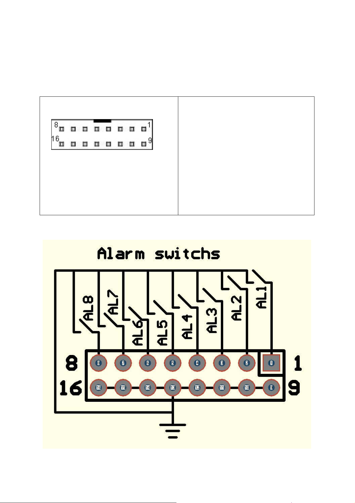
Also if the NP-14 option for 8 dry alarm contacts
The following 8 Pins 2 Rows Header Connector will replace the com1 DB9 position.
Table 1-2. 2x8 Header connector for 8 contacts alarm input
PIN SIGNAL DIRECTION
Header 2x8 - View looking into connector
(NP-14 side)
↓
↓More switch of alarm input information
↓↓
1 Alarm contact 1 input
2 Alarm contact 2 input
3 Alarm contact 3 input
4 Alarm contact 4 input
5 Alarm contact 5 input
6 Alarm contact 6 input
7 Alarm contact 7 input
8 Alarm contact 8 input
9 -16 Ground
Each alarm switch NO to NC, or
NC to NO be alarm active.
15
Page 16
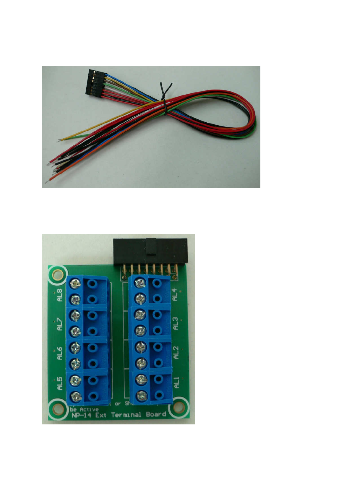
Option for external trig wires Part No. 86864528-00
For Alarm switch or alarm sensor direct connect with wires
Option for external trig alarm terminal board Part No. 86864700-00
For external terminal block
16
Page 17
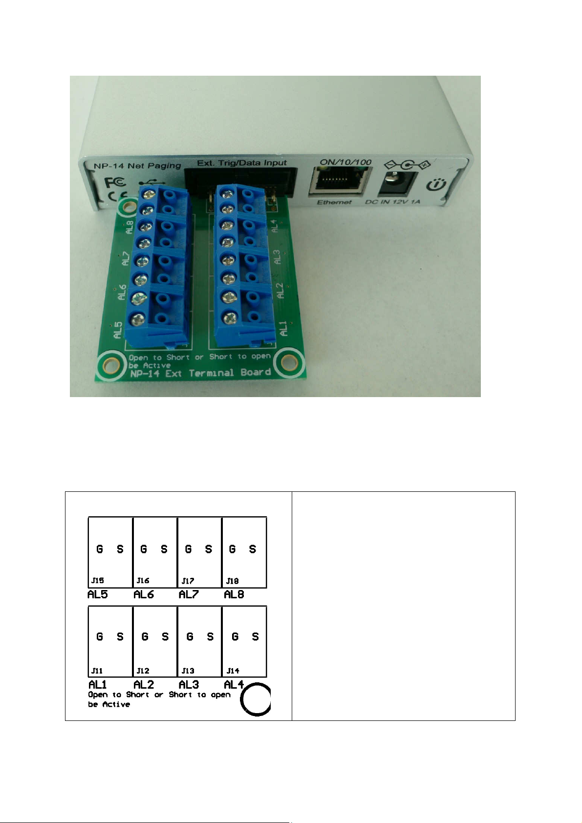
Use ext terminal board into to NP-14 Ext. trig port.
Table 1-3. Inside contacts input terminal (8 port) PIN SIGNAL DIRECTION
1 AL1 Alarm 1 in S= Trigger, G=Ground
2 AL2 Alarm 2 in S= Trigger, G=Ground
3 AL3 Alarm 3 in S= Trigger, G=Ground
4 AL4 Alarm 4 in S= Trigger, G=Ground
5 AL5 Alarm 5 in S= Trigger, G=Ground
6 AL6 Alarm 6 in S= Trigger, G=Ground
7 AL7 Alarm 7 in S= Trigger, G=Ground
8 AL8 Alarm 8 in S= Trigger, G=Ground
Each contact G-S open to short, or
short to open be alarm active.
17
Page 18
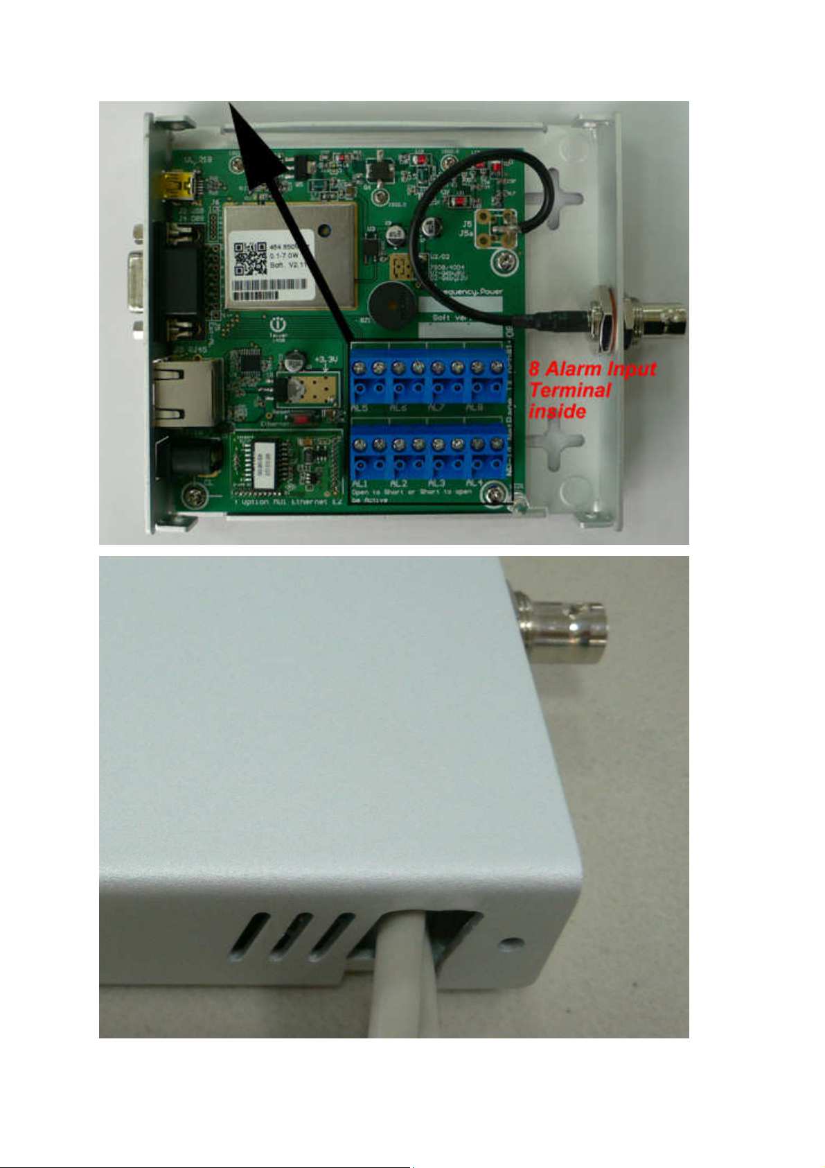
The alarm cable can be in/out on side hole of NP-14
18
Page 19
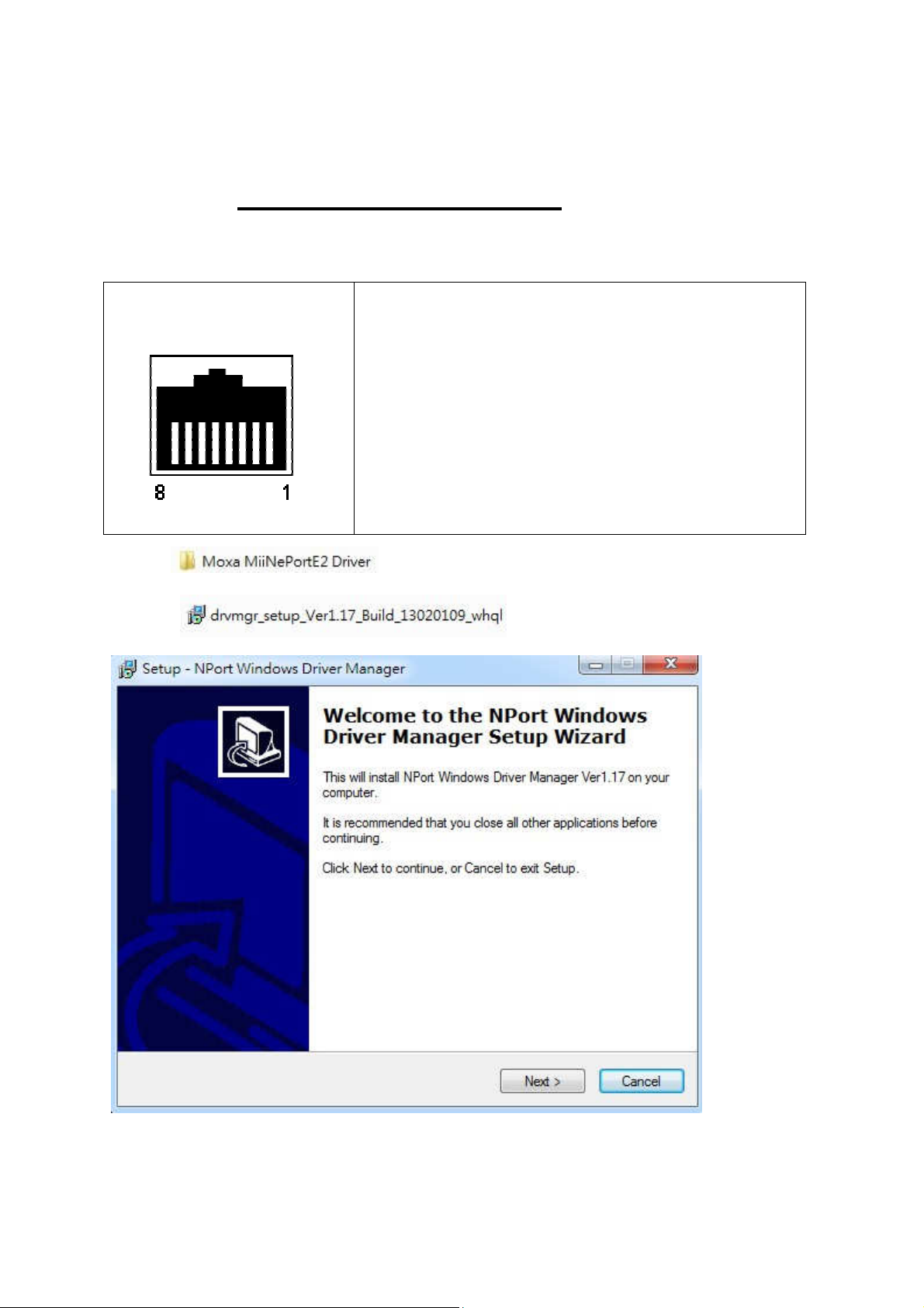
NP-14 Net-Paging System
Ethernet IP set up Guide
Table 1-4. RJ-45 ETHERNET PORTS (8 pin receptacle) PIN SIGNAL DIRECTION
RJ-45 - View looking into
receptacle (NP-14 side)
1 TD+
2 TD3 RD+
4 NA
5 NA
6 RD7 NA
8 NA
Click→
Click → to install NPort
19
Page 20
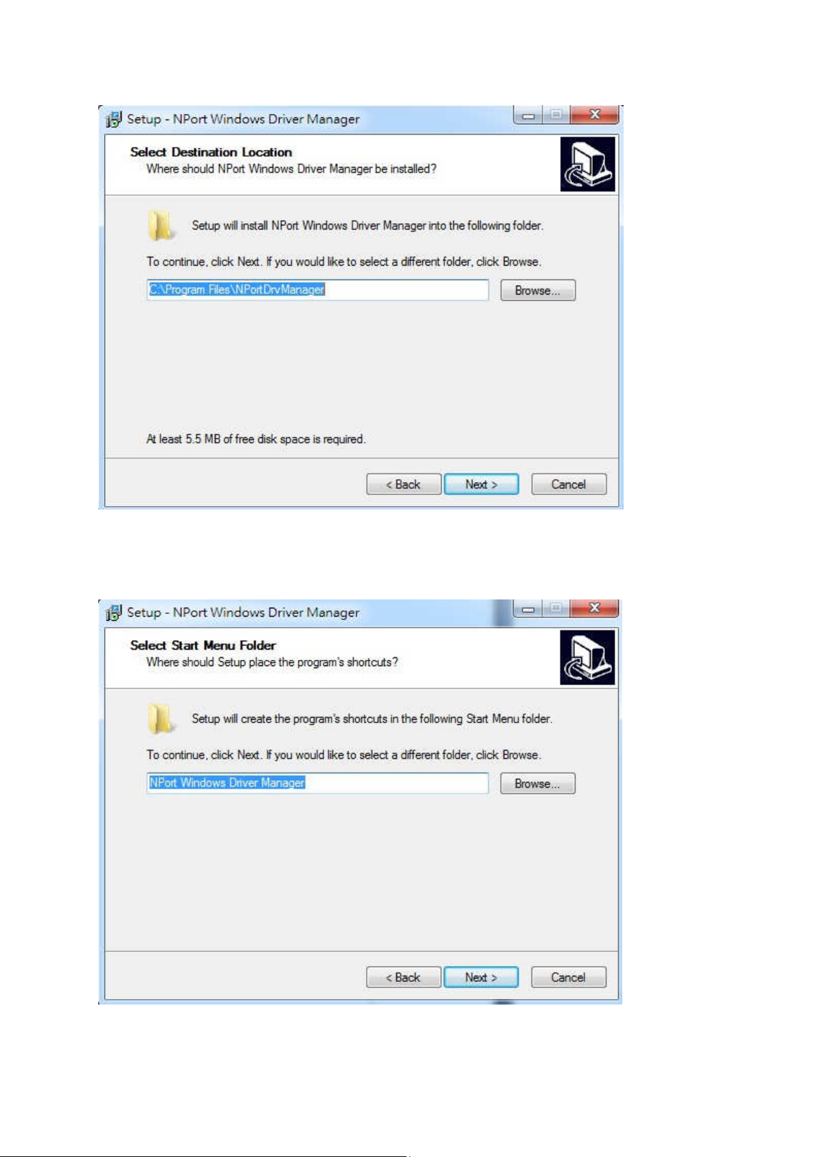
Click →Next
Click
20
→Next
Page 21
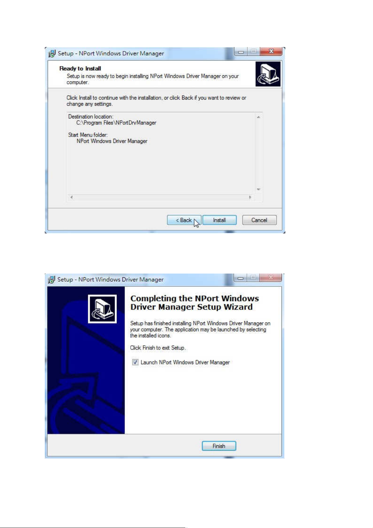
Clock →Install
Click
21
→Finish
Page 22
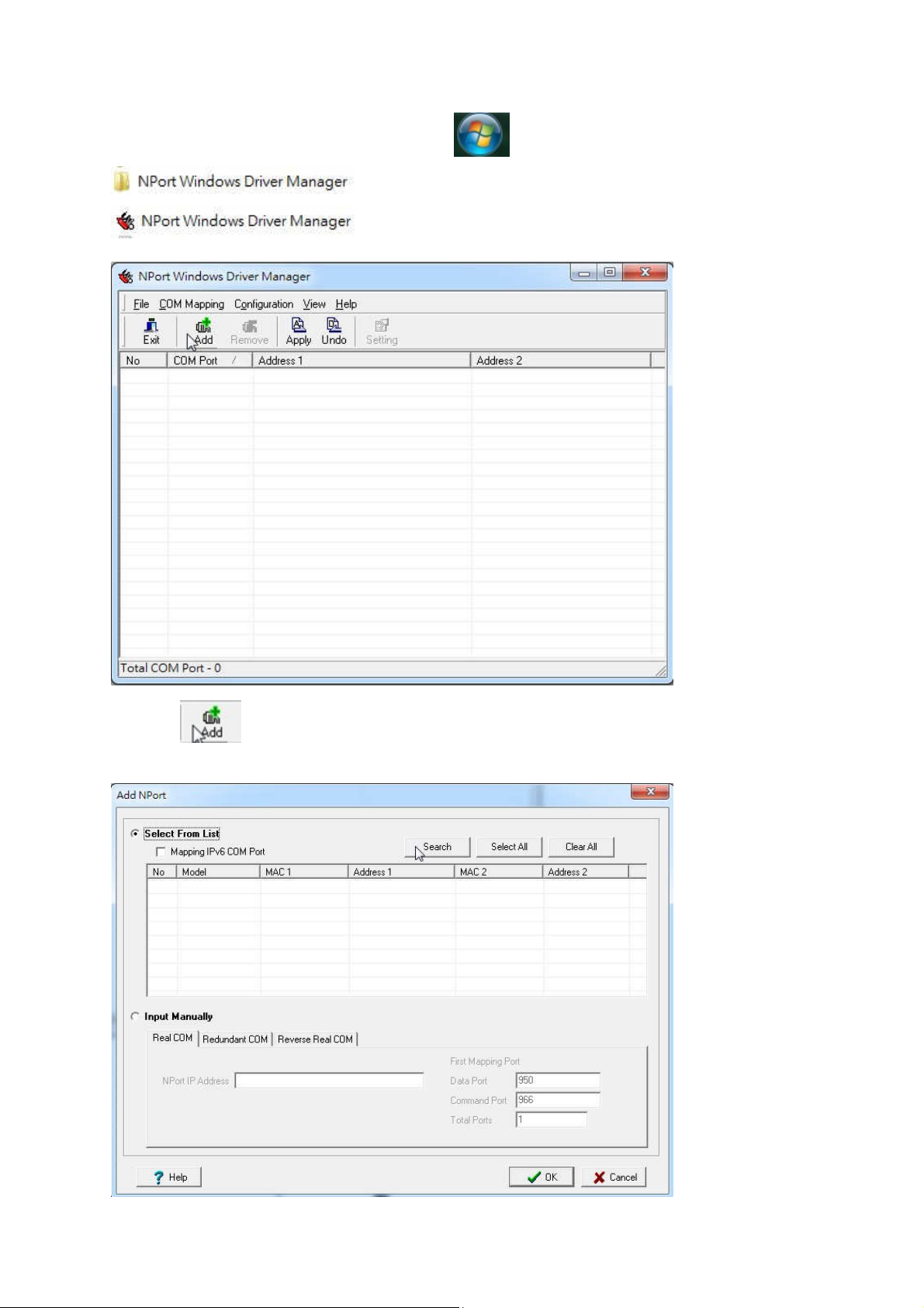
Click your PC →start then click →Nport
Click→
Click →Search
22
Page 23
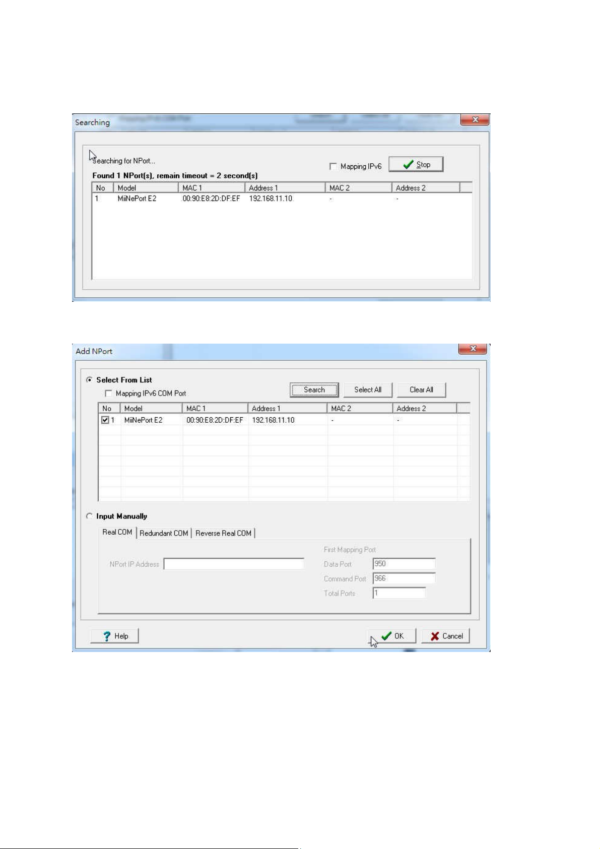
To find a IP address
Click → OK
Click→ Yes
23
Page 24
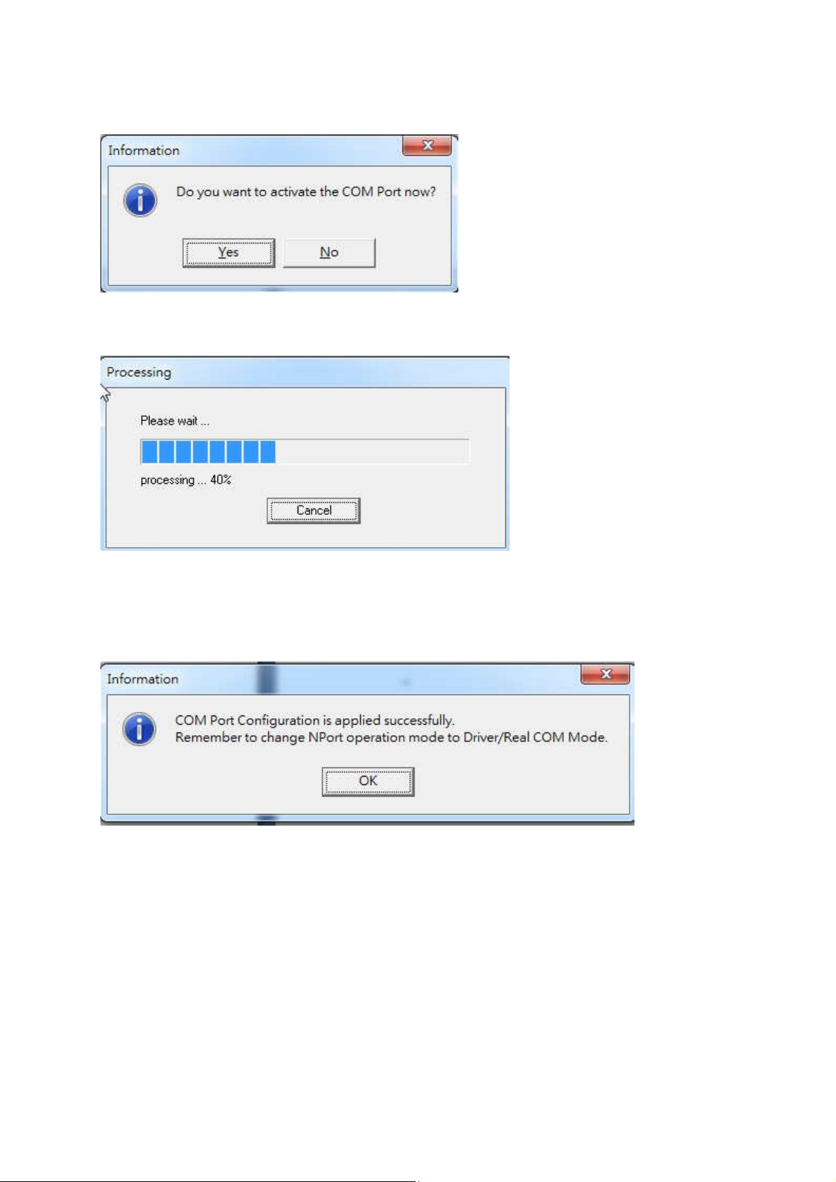
Waiting….
NPort is ready
24
Page 25
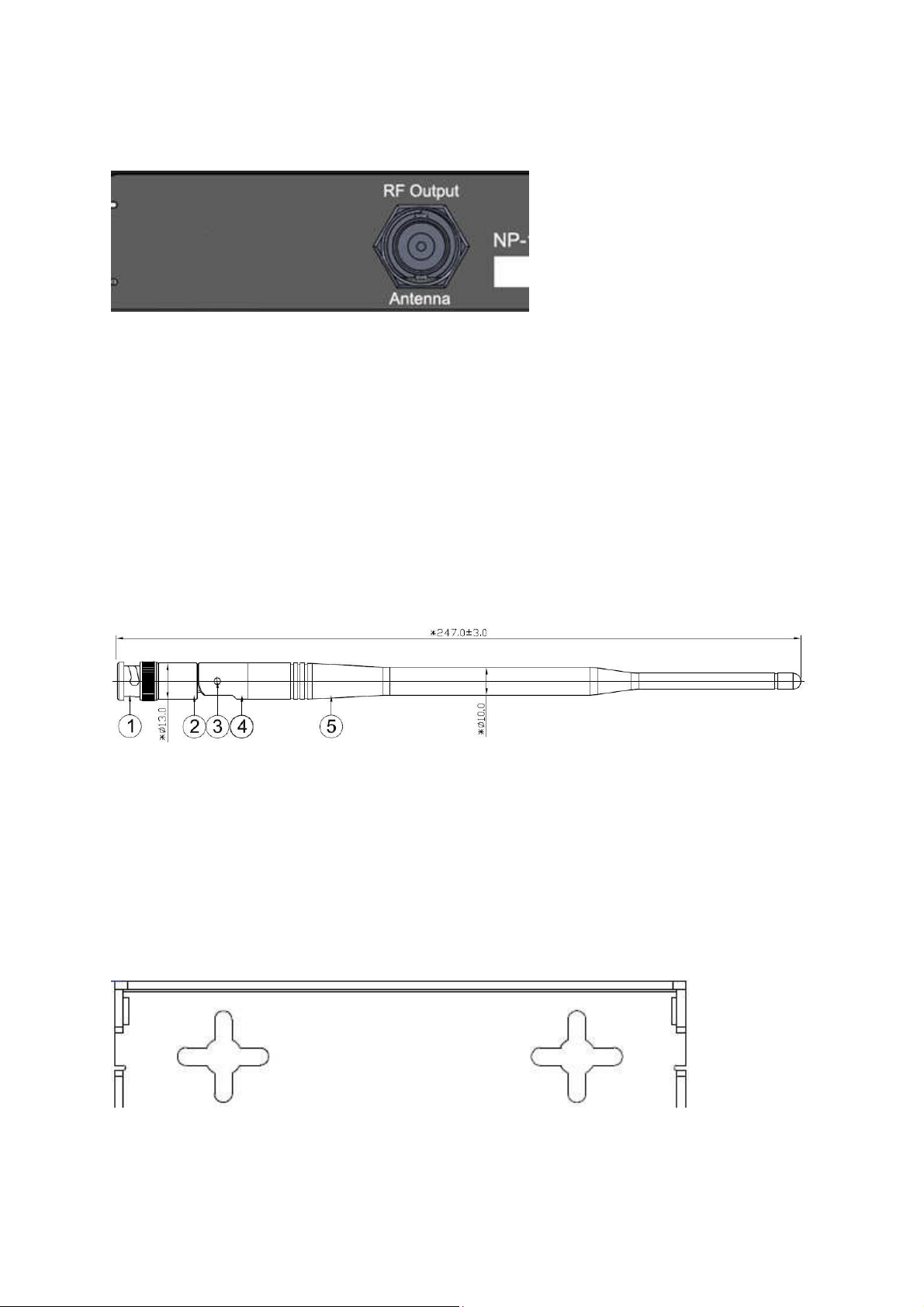
RF/Antenna output
RF/Antenna output of BNC
The BNC Jack for RF output or for antenna
IF RF power under 2 W, the NP-14 antenna can be used by the robber wipe antenna
IF RF power over 2W, the NP-14 must use the external antenna., which must be
Set the 1.5 meters away from the NP-14 unit to avoid the interference.
Folding Antenna
The BNC folding antenna for RF power under 2W use only
If RF power over 2W and UP must using external antenna.
Mount
Mount on the wall by screw max 5 mm
⊕
⊕------------------------ 66 mm -----------------------⊕⊕⊕⊕
⊕⊕
∮
25
Page 26
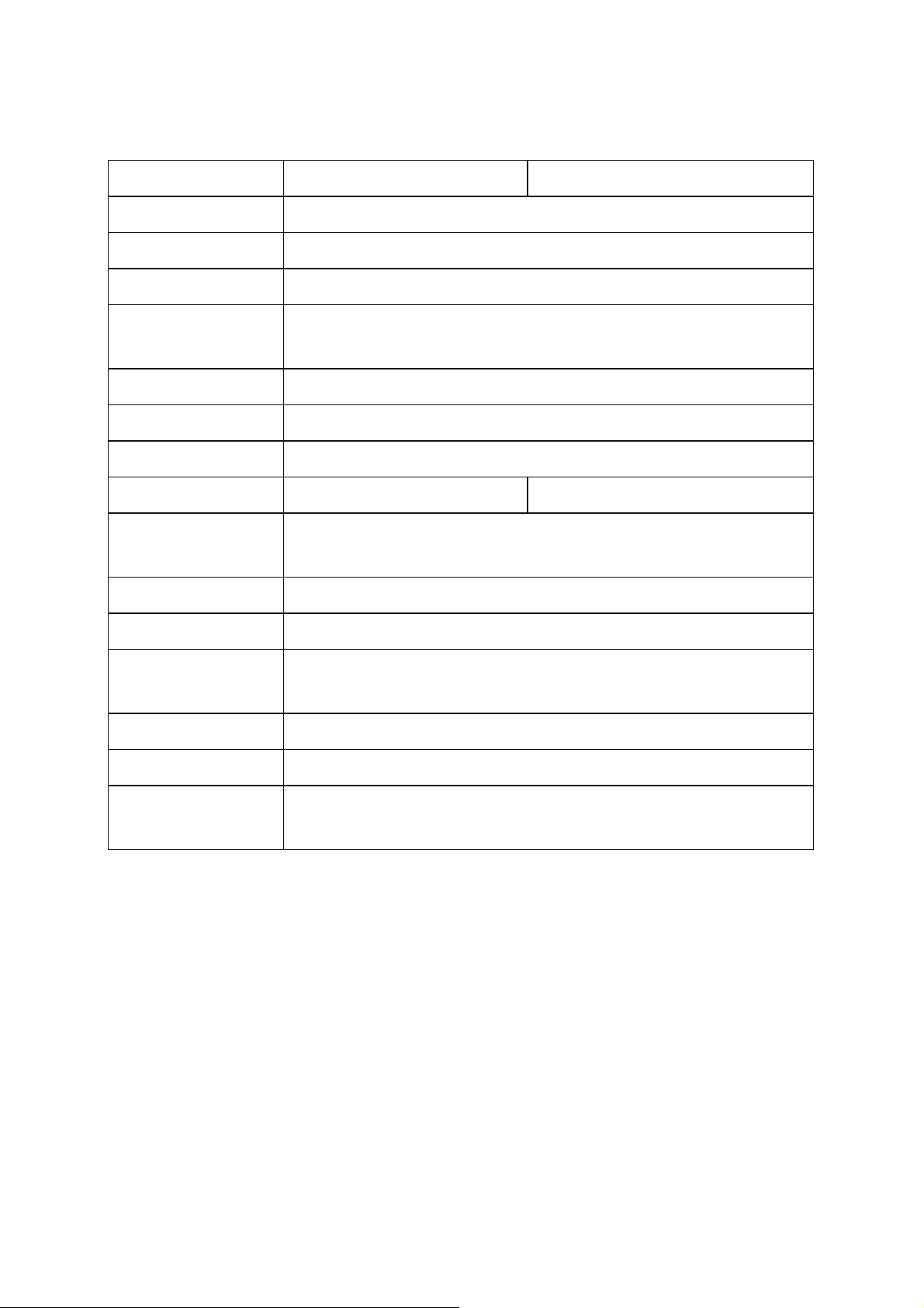
NP-14 NetPage Paging System Specifications
Frequency: 410-490 MHz Synthesized 868-915 MHz Synthesized
Paging format: POCSAG.
Pager Baud rate: 512bps / 1200bps / 2400bps.
Message type : ASCII
Channel Spacing:
6.25K / 12.5K / 25K. Frequency Synthesized by USB
programming
Modulation: NRZ NFSK, for POCSAG
Deviation: 3.5-4.5Khz
Stability:
10ppm.
RF output power: 0.1~7 W (programmable) 0.1~4 W (programmable)
RF output
BNC female (SMA female option)
connector:
P/C Interface: USB 2.0 and RS-232 9600bps
Ethernet: RJ-45 TCP/IP 10/100M
Operation
-25°C ~ 70°C
temperature:
Power Supply: DC 12V 1A(Minimum)
Size: 120 mm X 110 mm X 25 mm.
Model Weight:
0.8KGs. include AC 100~240 to DC 12V 2A switching power
adapter.
Notes: Specifications are subject to change without notice
CCW152241-002 ---- END ---- May.28.2015
26
 Loading...